EP3686364B1 - Method for blocking drainage of waste water comprising dissolved material, device and use of a floater - Google Patents
Method for blocking drainage of waste water comprising dissolved material, device and use of a floater Download PDFInfo
- Publication number
- EP3686364B1 EP3686364B1 EP20153282.7A EP20153282A EP3686364B1 EP 3686364 B1 EP3686364 B1 EP 3686364B1 EP 20153282 A EP20153282 A EP 20153282A EP 3686364 B1 EP3686364 B1 EP 3686364B1
- Authority
- EP
- European Patent Office
- Prior art keywords
- waste water
- outlet
- housing
- floater
- dissolved material
- Prior art date
- Legal status (The legal status is an assumption and is not a legal conclusion. Google has not performed a legal analysis and makes no representation as to the accuracy of the status listed.)
- Active
Links
Images

Classifications
-
- E—FIXED CONSTRUCTIONS
- E03—WATER SUPPLY; SEWERAGE
- E03F—SEWERS; CESSPOOLS
- E03F5/00—Sewerage structures
- E03F5/10—Collecting-tanks; Equalising-tanks for regulating the run-off; Laying-up basins
- E03F5/105—Accessories, e.g. flow regulators or cleaning devices
- E03F5/107—Active flow control devices, i.e. moving during flow regulation
Definitions
- the invention relates to a method for blocking drainage of waste water comprising a specific concentration of dissolved material. Furthermore, the invention relates to a device, in particular to perform the method according to the invention.
- a method according to the preamble of claim 1 is known from DE 102 21 208 A1 .
- Waste water contains several different substances which can cause dangerous conditions at least when a specific concentration of at least one of these different substances is reached or exceeded.
- One of these substances can be urea.
- Waste water could be rainwater also. Especially in cases that rainwater is running off hard surfaces like streets, roofs etc., the rainwater is very often contaminated and therefore waste water.
- floater for providing a temporary blockage of fluid paths.
- fluid paths can be unblocked by the floater which starts to float as soon as a certain volume of fluid is collected, thereby allowing a fluid path to become unblocked.
- bad odors being returned from a drain can be avoided for example.
- a floater usually depends on the volume of fluid collected inside a housing or the like, but is independent from ingredients or substances comprised by the collected fluid volume.
- the above-mentioned DE 102 21 208 A1 discloses a device for the recycling of waste water, that has vessel with an inlet for waste water, a pump arranged within the vessel and a distributor.
- the pump feeds the waste water through an outlet to the distributor, which is controlled in such a way that, on the one hand, if there is an increased salt concentration, the waste water is fed into a mixing reservoir for reuse or, on the other hand, if there is waste water without increased salt concentration, it is discharged through an outlet.
- the disadvantage here is that the distributor is a dependently operating mechanism which just works with a control system and therefore comprises a higher complexity.
- a method for blocking drainage of waste water comprising a specific concentration of dissolved material comprises the following steps:
- the invention is based on the idea to provide an automatically, self-acting mechanism which is capable of preventing drainage or discharge of fluid which comprises a critical concentration of dissolved material such as urea.
- a floater is utilized which is configured to react to the concentration of dissolved material, preferably to the concentration of urea.
- Drainage of waste water through the first outlet can be provided when a minimum amount of waste water collected in the housing is reached or exceeded. Thus, at least a minimum volume of waste water is collected and stored within the housing before a drainage or a block of the drainage of the waste water can occur.
- the specific concentration of dissolved material causes the waste water to be heavier or lighter than water.
- the dissolved material is urea, glycol, alcohol and/or salt.
- the term dissolved material can specifically be referred to urea in the sense of the present invention.
- a specific concentration of urea can be relevant with regard to an automatical blockage of waste water drainage according to the method of the present invention.
- the floater is configured to provide a reaction to a change of, namely an increase of, the concentration of dissolved material. Consequently, a concentration of dissolved material reaching and/or exceeding the predeterminable specific concentration of dissolved material causes the floater to float and to block the first outlet such that waste water comprising at least the specific concentration of dissolved material, in particular of urea, cannot be drained through the first outlet anymore.
- the predeterminable, specific concentration of dissolved material can thus be considered as a concentration limit in the context of the present invention.
- this concentration limit of dissolved material in terms of the specific concentration is decisive for the drainage of waste water through the first, usual outlet. It can be avoided that waste water being polluted / contaminated with a critical concentration of dissolved material, such as urea or the like, is drained / discharged along the first outlet, preferably representing a usually used drainage system in the sense of the present invention.
- the specific concentration of dissolved material, in particular of urea is set to less than 50 %, preferably to 30 %, more preferably to 25%, more preferably to 20%, even more preferably to 10%.
- the floater is configured to provide blockage of the first outlet at an predeterminable specific concentration of dissolved material.
- the floater performs a movement, in particular a linear movement, to block the outlet such that waste water cannot be drained through / along the first outlet.
- the floater can move at least between a blocked state of the first outlet and a release / free state in order to provide a blockage of drainage of waste water temporarily and dependent on the concentration of dissolved material within the collected volume of waste water.
- the waste water is drained from the housing through the first outlet when a minimum volume of waste water collected within the housing is reached or exceeded and the concentration of dissolved material is below the specific concentration.
- the first outlet is arranged such that at least a minimum volume of waste water is collected and stored within the housing.
- this minimum amount of waste water represents a certain fluid height within the housing.
- the minimum volume of waste water to be collected before any drainage of waste water can be achieved is predeterminable.
- the waste water is drained through a second outlet when a maximum volume of waste water is collected and the first outlet is at least partially blocked by the floater.
- a second outlet can be arranged along the housing such that a maximum volume of waste water collectable within the housing is predefined, preferably in case of at least a partial blockage of the drainage through the first outlet.
- the collected volume of waste water can increase until a maximum volume of waste water is collected within the housing. Drainage of the waste water, collected until a maximum volume is reached and comprising at least the specific concentration of dissolved material, can be drained through the second outlet.
- the second outlet is provided as a special fluid path to provide a secure drainage of the polluted / contaminated waste water.
- a secure removal of the waste water comprising too much dissolved material is achieved.
- Another aspect of the invention is to provide a device for blocking drainage waste water comprising a specific concentration of dissolved material, whereby the device comprises:
- the floater can be configured to react to the concentration of dissolved material within the collected volume of waste water.
- the first outlet can be blocked by the floater.
- the floater is arranged within a frame which is provided in the housing, whereby the floater is replaceable together with the frame as a floater assembly.
- the floater is exchangeable in an easy and comfortable manner.
- An option for adjusting the floater to a predeterminable specific concentration of dissolved material is provided.
- the floater can be provided in combination with a guidance means, e.g. a cage, which is arranged within the frame as well.
- a guidance means e.g. a cage
- the floater is configured to move along a predetermined path, provided by the guidance means, in order to block the first outlet temporarily.
- the guidance means can be provided as a cage, in particular as at least three parallel, longitudinal beams, in order to guide the floater along a linear movement direction.
- the housing comprises a second outlet which is arranged to provide drainage of waste water collected in the housing when the first outlet is at least partially blocked by the floater.
- waste water comprising at least the specific concentration of dissolved material can be drained when a maximum volume of waste water is collected and the first outlet is at least partially blocked by the floater.
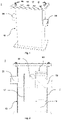
- Fig. 1 a preferred embodiment of the device 1 is illustrated comprising a housing 10.
- the device 1 is provided with an inlet 20 and a first outlet 30 arranged along the housing 10.
- the inlet 20 is arranged at a higher height along the housing 10 than the first outlet 30.
- fluid in particular waste water, can be collected within the housing 10 and drained through the first outlet 30 when a minimum volume of fluid 2, reaching to a minimum height, is collected.
- the inlet 20 and the first outlet 30 are arranged at opposing sides of the housing 10. However, it is also possible to arrange the inlet 20 and the first outlet at the same side or adjacent sides of the housing 10.
- Fig. 2 a section view of the device 1 according to Fig. 1 is shown when the first outlet 30 is unblocked.
- a minimum volume of waste water 2 is collected within the housing 10 such that drainage through the first outlet 30 can be provided, in particular drainage of additional waste water 2 being collected.
- a flow barrier 12 is arranged to provide a controlled inflow of waste water 2 through the inlet 20 into the housing 10.
- the floater 40 is in a free state or release state according to Fig. 2 as the minimum volume of collected waste water 2 comprises a concentration of dissolved material which is lower than a predetermined specific concentration of dissolved material.
- the first outlet 30 is unblocked and the collected waste water 2 can be drained through the first outlet 30.
- the device 1 is provided with a second outlet 32.
- the second outlet 32 is positioned above the first outlet 30 and preferably above the inlet 20. In case drainage of waste water along the first outlet 10 is blocked by the floater 40, the drainage through the second outlet 32 can be provided.
- waste water 2 comprising a concentration of e.g. urea, which is equal to or exceeding the predefinable specific concentration, can be drained in a controlled manner along the second outlet 32 whereas drainage along the usual first outlet 30 is prevented.
- the second outlet can be considered as a special outlet for draining polluted / contaminated waste water 2.
- the floater 40 is arranged within a frame 50 according to Fig. 2 .
- the floater 40 is easily exchangeable, e.g. to be adaptable to a specific concentration of dissolved material at which drainage of waste water along the first outlet 30 shall be blocked blocked.
- Fig. 3 a perspective section view of the device 1 according to Fig. 1 is illustrated, when the first outlet 30 is blocked by the floater 40. Namely, the floater 40 starts to float when the specific concentration of dissolved material within the collected waste water 2 inside the housing 10 is reached or exceeded.
- the floater 40 provides a fluid tight closure of the first outlet 30 according to Fig. 3 .
- drainage of waste water 2 along the first outlet 30 is blocked.
- Fig. 4 a detail view of the floater 40 within a frame 50 is shown, particularily in accordance with Fig. 3 .
- the floater 40 is arranged within the frame 50.
- the floater 40 is arranged in combination with a guidance means 42 within the frame 50, whereby the guidance means 42 enables the floater 40 to be movable along a linear movement direction.
- the guidance means 42 is provided with at least three, preferably four, longitudinal beams in order to guide the floater 40 between a free / unblocked / release state and a floating / blocked state, whereby drainage of waste water along the first outlet 30 is blocked.
- the present invention provides a comfortable and adaptable solution to prevent polluted / contaminated waste water 2, comprising a specific concentration of dissolved material such as urea, to be drained along / through a first outlet 30 of a device 1, and thus along a usually used drainage system.
Landscapes
- Health & Medical Sciences (AREA)
- Life Sciences & Earth Sciences (AREA)
- Engineering & Computer Science (AREA)
- Hydrology & Water Resources (AREA)
- Public Health (AREA)
- Water Supply & Treatment (AREA)
- Physical Water Treatments (AREA)
- Degasification And Air Bubble Elimination (AREA)
Description
- The invention relates to a method for blocking drainage of waste water comprising a specific concentration of dissolved material. Furthermore, the invention relates to a device, in particular to perform the method according to the invention. A method according to the preamble of
claim 1 is known fromDE 102 21 208 A1 . - Waste water contains several different substances which can cause dangerous conditions at least when a specific concentration of at least one of these different substances is reached or exceeded. One of these substances can be urea. Thus, drainage of waste water which comprises a critical, specific concentration of a specific substance such as urea, into the usual waste water drainage system has to be prevented. Waste water could be rainwater also. Especially in cases that rainwater is running off hard surfaces like streets, roofs etc., the rainwater is very often contaminated and therefore waste water.
- Use of floater for providing a temporary blockage of fluid paths is known. E.g. fluid paths can be unblocked by the floater which starts to float as soon as a certain volume of fluid is collected, thereby allowing a fluid path to become unblocked. Thus, bad odors being returned from a drain can be avoided for example.
- However, such use of a floater usually depends on the volume of fluid collected inside a housing or the like, but is independent from ingredients or substances comprised by the collected fluid volume.
- The above-mentioned
DE 102 21 208 A1 discloses a device for the recycling of waste water, that has vessel with an inlet for waste water, a pump arranged within the vessel and a distributor. The pump feeds the waste water through an outlet to the distributor, which is controlled in such a way that, on the one hand, if there is an increased salt concentration, the waste water is fed into a mixing reservoir for reuse or, on the other hand, if there is waste water without increased salt concentration, it is discharged through an outlet. The disadvantage here is that the distributor is a dependently operating mechanism which just works with a control system and therefore comprises a higher complexity. - It is an object of the invention to provide a method for blocking drainage of waste water comprising a specific concentration of dissolved material, in particular of Adblue, whereby the method allows to be easily applied and conductable in a cost-efficient manner. Further, it is an object of the invention to provide a device for blocking drainage of waste water.
- According to the present invention a method for blocking drainage of waste water comprising a specific concentration of dissolved material is provided, whereby the method comprises the following steps:
- supplying waste water into a housing through an inlet;
- collecting the waste water within the housing; and
- draining the waste water from the housing through a first outlet, when at least a minimum volume of waste water is collected;
- The invention is based on the idea to provide an automatically, self-acting mechanism which is capable of preventing drainage or discharge of fluid which comprises a critical concentration of dissolved material such as urea. Thus, a floater is utilized which is configured to react to the concentration of dissolved material, preferably to the concentration of urea.
- Drainage of waste water through the first outlet can be provided when a minimum amount of waste water collected in the housing is reached or exceeded. Thus, at least a minimum volume of waste water is collected and stored within the housing before a drainage or a block of the drainage of the waste water can occur.
- According to one embodiment, the specific concentration of dissolved material, causes the waste water to be heavier or lighter than water.
- According to a preferred embodiment of the invention, the dissolved material is urea, glycol, alcohol and/or salt.
- Preferably, the term dissolved material can specifically be referred to urea in the sense of the present invention. Thus, in particular a specific concentration of urea can be relevant with regard to an automatical blockage of waste water drainage according to the method of the present invention.
- Thus, the floater is configured to provide a reaction to a change of, namely an increase of, the concentration of dissolved material. Consequently, a concentration of dissolved material reaching and/or exceeding the predeterminable specific concentration of dissolved material causes the floater to float and to block the first outlet such that waste water comprising at least the specific concentration of dissolved material, in particular of urea, cannot be drained through the first outlet anymore.
- The predeterminable, specific concentration of dissolved material can thus be considered as a concentration limit in the context of the present invention. In particular, this concentration limit of dissolved material in terms of the specific concentration is decisive for the drainage of waste water through the first, usual outlet. It can be avoided that waste water being polluted / contaminated with a critical concentration of dissolved material, such as urea or the like, is drained / discharged along the first outlet, preferably representing a usually used drainage system in the sense of the present invention.
- In another embodiment, the specific concentration of dissolved material, in particular of urea, is set to less than 50 %, preferably to 30 %, more preferably to 25%, more preferably to 20%, even more preferably to 10%.
- Consequently, the floater is configured to provide blockage of the first outlet at an predeterminable specific concentration of dissolved material.
- In a further preferred embodiment of the invention, the floater performs a movement, in particular a linear movement, to block the outlet such that waste water cannot be drained through / along the first outlet.
- Thus, the floater can move at least between a blocked state of the first outlet and a release / free state in order to provide a blockage of drainage of waste water temporarily and dependent on the concentration of dissolved material within the collected volume of waste water.
- According to one embodiment of the invention, the waste water is drained from the housing through the first outlet when a minimum volume of waste water collected within the housing is reached or exceeded and the concentration of dissolved material is below the specific concentration.
- In consequence, the first outlet is arranged such that at least a minimum volume of waste water is collected and stored within the housing. In particular, this minimum amount of waste water represents a certain fluid height within the housing. Preferably, by arranging the first outlet at a certain height along the housing, the minimum volume of waste water to be collected before any drainage of waste water can be achieved, is predeterminable.
- In another embodiment of the invention, the waste water is drained through a second outlet when a maximum volume of waste water is collected and the first outlet is at least partially blocked by the floater.
- In particular, a second outlet can be arranged along the housing such that a maximum volume of waste water collectable within the housing is predefined, preferably in case of at least a partial blockage of the drainage through the first outlet.
- Thus, in case the waste water comprises at least a specific concentration of dissolved material and the first outlet is blocked for drainage consequently, the collected volume of waste water can increase until a maximum volume of waste water is collected within the housing. Drainage of the waste water, collected until a maximum volume is reached and comprising at least the specific concentration of dissolved material, can be drained through the second outlet.
- The second outlet is provided as a special fluid path to provide a secure drainage of the polluted / contaminated waste water. Thus, a secure removal of the waste water comprising too much dissolved material is achieved.
- Another aspect of the invention is to provide a device for blocking drainage waste water comprising a specific concentration of dissolved material, whereby the device comprises:
- a housing,
- an inlet such that waste water is introducible into the housing,
- an outlet such that waste water is drainable from the housing, when a minimum volume of waste water collected in the housing is collected or exceeded, and
- a floater,
- Thus, the floater can be configured to react to the concentration of dissolved material within the collected volume of waste water. Preferably, only if a minimum volume of waste water is collected, the first outlet can be blocked by the floater.
- According to another embodiment, the floater is arranged within a frame which is provided in the housing, whereby the floater is replaceable together with the frame as a floater assembly.
- In consequence, the floater is exchangeable in an easy and comfortable manner. An option for adjusting the floater to a predeterminable specific concentration of dissolved material is provided.
- Preferably, the floater can be provided in combination with a guidance means, e.g. a cage, which is arranged within the frame as well. Thus, the floater is configured to move along a predetermined path, provided by the guidance means, in order to block the first outlet temporarily. Preferably, the guidance means can be provided as a cage, in particular as at least three parallel, longitudinal beams, in order to guide the floater along a linear movement direction.
- In a further embodiment, the housing comprises a second outlet which is arranged to provide drainage of waste water collected in the housing when the first outlet is at least partially blocked by the floater.
- By arrangement of the second outlet at a height along the housing which exceeds the height of the first outlet, waste water comprising at least the specific concentration of dissolved material can be drained when a maximum volume of waste water is collected and the first outlet is at least partially blocked by the floater.
- In the following, the present invention is described in more detail with reference to an embodiment as illustrated by the enclosed Figures.
- It is shown:
- Fig. 1
- a perspective illustration of an embodiment of a device according to the present invention;
- Fig. 2
- a section view of the device according to
Fig. 1 , when the first outlet is unblocked; - Fig. 3
- a perspective section view of the device according to
Fig. 1 , when the first outlet is blocked by a floater; and - Fig. 4
- a detail view of the floater within a frame.
- In
Fig. 1 a preferred embodiment of thedevice 1 is illustrated comprising ahousing 10. - Furthermore, the
device 1 is provided with aninlet 20 and afirst outlet 30 arranged along thehousing 10. Preferably, theinlet 20 is arranged at a higher height along thehousing 10 than thefirst outlet 30. Thus, fluid, in particular waste water, can be collected within thehousing 10 and drained through thefirst outlet 30 when a minimum volume offluid 2, reaching to a minimum height, is collected. - According to
Fig. 1 , theinlet 20 and thefirst outlet 30 are arranged at opposing sides of thehousing 10. However, it is also possible to arrange theinlet 20 and the first outlet at the same side or adjacent sides of thehousing 10. - In
Fig. 2 a section view of thedevice 1 according toFig. 1 is shown when thefirst outlet 30 is unblocked. - According to
Fig. 2 , a minimum volume ofwaste water 2 is collected within thehousing 10 such that drainage through thefirst outlet 30 can be provided, in particular drainage ofadditional waste water 2 being collected. - Next to the
inlet 20, aflow barrier 12 is arranged to provide a controlled inflow ofwaste water 2 through theinlet 20 into thehousing 10. - Further, the
floater 40 is in a free state or release state according toFig. 2 as the minimum volume of collectedwaste water 2 comprises a concentration of dissolved material which is lower than a predetermined specific concentration of dissolved material. Thus, despite a minimum volume of waste water collected inside thehousing 10, thefirst outlet 30 is unblocked and the collectedwaste water 2 can be drained through thefirst outlet 30. - Additionally, according to
Fig. 2 , thedevice 1 is provided with asecond outlet 32. Thesecond outlet 32 is positioned above thefirst outlet 30 and preferably above theinlet 20. In case drainage of waste water along thefirst outlet 10 is blocked by thefloater 40, the drainage through thesecond outlet 32 can be provided. Thus,waste water 2 comprising a concentration of e.g. urea, which is equal to or exceeding the predefinable specific concentration, can be drained in a controlled manner along thesecond outlet 32 whereas drainage along the usualfirst outlet 30 is prevented. The second outlet can be considered as a special outlet for draining polluted / contaminatedwaste water 2. - Furthermore, the
floater 40 is arranged within aframe 50 according toFig. 2 . Thus, thefloater 40 is easily exchangeable, e.g. to be adaptable to a specific concentration of dissolved material at which drainage of waste water along thefirst outlet 30 shall be blocked blocked. - In
Fig. 3 a perspective section view of thedevice 1 according toFig. 1 is illustrated, when thefirst outlet 30 is blocked by thefloater 40. Namely, thefloater 40 starts to float when the specific concentration of dissolved material within the collectedwaste water 2 inside thehousing 10 is reached or exceeded. - In particular, the
floater 40 provides a fluid tight closure of thefirst outlet 30 according toFig. 3 . Thus, drainage ofwaste water 2 along thefirst outlet 30 is blocked. - Consequently, according to
Fig. 3 thewaste water 2 will be collected until a maximum volume is reached and thewaste water 2 can be drained along thesecond outlet 32. - In
Fig. 4 a detail view of thefloater 40 within aframe 50 is shown, particularily in accordance withFig. 3 . - The
floater 40 is arranged within theframe 50. In particular, thefloater 40 is arranged in combination with a guidance means 42 within theframe 50, whereby the guidance means 42 enables thefloater 40 to be movable along a linear movement direction. - In particular, the guidance means 42 is provided with at least three, preferably four, longitudinal beams in order to guide the
floater 40 between a free / unblocked / release state and a floating / blocked state, whereby drainage of waste water along thefirst outlet 30 is blocked. By providing thefloater 40, in particular in combination with the guidance means 42, within theframe 50, an easily adaptable solution for different predeterminable specific concentrations of dissolved material within thewaste water 2 can be achieved. - In summary, the present invention provides a comfortable and adaptable solution to prevent polluted / contaminated
waste water 2, comprising a specific concentration of dissolved material such as urea, to be drained along / through afirst outlet 30 of adevice 1, and thus along a usually used drainage system. - Consequently, drainage of contaminated
waste water 2 can be avoided in a self-acting and passive manner, dependent on the dissolved material concentration of the collectedwaste water 2. -
- 1
- Device
- 2
- Waste water
- 10
- Housing
- 12
- Flow barrier
- 20
- Inlet
- 30
- First outlet
- 32
- Second outlet
- 40
- Floater
- 42
- Guidance element
- 50
- Frame
Claims (10)
- Method for blocking drainage of waste water (2) comprising a specific concentration of dissolved material, whereby the method comprises the following steps:- supplying waste water into a housing (10) through an inlet (20);- collecting the waste water (2) within the housing (10);- draining the waste water (2) from the housing (10) through a first outlet (30), when at least a minimum volume of waste water (2) is collected, whereby the drainage of waste water (2) through the first outlet (30) is automatically blocked when the waste water (2) collected inside the housing (10) comprises the specific concentration of dissolved material,characterized in that
a floater (40) begins to float at the specific concentration of dissolved material such that the first outlet (30) can be blocked. - Method according to claim 1,
characterized in that
the specific concentration of dissolved material, causes the waste water to be heavier or lighter than water. - Method according to claim 1 or 2,
characterized in that
the dissolved material is urea, glycol, alcohol and/or salt. - Method according to one of the preceding claims,
characterized in that
the specific concentration of dissolved material is set to less than 50 %, preferably to 30 %, more preferably to 25%, more preferably to 20%, more preferably to 10%. - Method according to one of the preceding claims,
characterized in that
the floater (40) performs a movement, in particular a linear movement, to block the outlet (30) such that waste water cannot be drained through the first outlet (30). - Method according to one of the preceding claims,
characterized in that
the waste water (2) is drained from the housing (10) through the first outlet (30) when a minimum volume of waste water (2) collected within the housing (10) is reached and the concentration of dissolved material is below the specific concentration. - Method according to one of the preceding claims,
characterized in that
the waste water (2) is drained through a second outlet (32) when a maximum volume of waste water (2) is collected and the first outlet (30) is at least partially blocked by the floater (40). - Device (1) for blocking drainage waste water (2) comprising a specific concentration of dissolved material, whereby the device (1) comprises:- a housing (10),- an inlet (20) such that waste water (2) is introducible into the housing (10),- an outlet (30) such that waste water (2) is drainable from the housing (10), when at least a minimum volume of waste water (2) is collected or exceeded, and- a floater (40),whereby the floater (40) begins to float and is configured to block the first outlet (30), when the waste water (2) collected in the housing (10) reaches a minimum volume and comprises the specific concentration of dissolved material.
- Device (1) according to claim 8,
characterized in that
the floater (40) is arranged within a frame (50) which is provided in the housing (10), whereby the floater (40) is replaceable together with the frame as a floater assembly. - Device (1) according to claim 8 or 9,
characterized in that
the housing (10) comprises a second outlet (32) which is arranged to provide drainage of waste water (2) collected in the housing (10) when the first outlet (30) is at least partially blocked by the floater (40).
Applications Claiming Priority (1)
| Application Number | Priority Date | Filing Date | Title |
|---|---|---|---|
| NL2022453A NL2022453B1 (en) | 2019-01-25 | 2019-01-25 | Method for blocking drainage of waste water comprising dissolved material, device and use of a floater |
Publications (2)
| Publication Number | Publication Date |
|---|---|
| EP3686364A1 EP3686364A1 (en) | 2020-07-29 |
| EP3686364B1 true EP3686364B1 (en) | 2022-11-16 |
Family
ID=66049653
Family Applications (1)
| Application Number | Title | Priority Date | Filing Date |
|---|---|---|---|
| EP20153282.7A Active EP3686364B1 (en) | 2019-01-25 | 2020-01-23 | Method for blocking drainage of waste water comprising dissolved material, device and use of a floater |
Country Status (3)
| Country | Link |
|---|---|
| EP (1) | EP3686364B1 (en) |
| NL (1) | NL2022453B1 (en) |
| PL (1) | PL3686364T3 (en) |
Family Cites Families (2)
| Publication number | Priority date | Publication date | Assignee | Title |
|---|---|---|---|---|
| US4899774A (en) * | 1989-05-22 | 1990-02-13 | Keller Jr R Davidson | Fluidic density control for chlor alkali cells |
| DE10221208B4 (en) * | 2002-05-13 | 2006-06-08 | Brennecke, Peer, Dipl.-Ing. | Device for collecting saline waste water |
-
2019
- 2019-01-25 NL NL2022453A patent/NL2022453B1/en active
-
2020
- 2020-01-23 PL PL20153282.7T patent/PL3686364T3/en unknown
- 2020-01-23 EP EP20153282.7A patent/EP3686364B1/en active Active
Also Published As
| Publication number | Publication date |
|---|---|
| PL3686364T3 (en) | 2023-06-12 |
| NL2022453B1 (en) | 2020-08-18 |
| EP3686364A1 (en) | 2020-07-29 |
Similar Documents
| Publication | Publication Date | Title |
|---|---|---|
| EP0935699B1 (en) | Gross pollution filter | |
| FI115828B (en) | Apparatus for separating solid constituents from flowing liquids | |
| US9970188B2 (en) | Drainage device | |
| KR20100083129A (en) | Water treatment and bypass system | |
| EP2335794B1 (en) | Fluid retention device | |
| KR101629695B1 (en) | A stormwater gully | |
| JP2005166267A (en) | Ion exchange filter | |
| SE524049C2 (en) | Settling device | |
| EP3686364A1 (en) | Method for blocking drainage of waste water comprising dissolved material, device and use of a floater | |
| EP2299186B1 (en) | Method for transporting thermal energy in a sewage channel. | |
| US20060006125A1 (en) | Oil from water separation system | |
| AU2018422676A1 (en) | Filters with dynamic pore sizes | |
| US4276165A (en) | Sludge siphon collector with de-gasing header | |
| CA2565142A1 (en) | Heat exchanger and installation for extracting heat from waste water | |
| WO1999054564A1 (en) | Rapid storm water filtration | |
| DE102009032047A1 (en) | Air exchange device for aerating and/or deaerating room of building, has condensate discharge device comprising collecting tray, which comprises outlet that is connected with atmosphere surrounding room | |
| DE2907998A1 (en) | Sewage plant rain water separator - has surface water removal outlet in collector chamber on separating side | |
| JPH0123183B2 (en) | ||
| KR102892495B1 (en) | System and method of scum collection in wastewater treatment systems | |
| AU720388B2 (en) | Gross pollution filter | |
| EP2394724A2 (en) | Separator assembly and device for handling waste water | |
| JP7838915B2 (en) | drainage tank | |
| US6199329B1 (en) | Liquid storage system | |
| DE102011120543A1 (en) | Valve device used in exhaust system of fuel cell system, has float to cover liquid orifices in state without predetermined amount of orifices and to release orifices in floated state with liquid quantity above predefined quantity | |
| WO2001030481A1 (en) | Screening apparatus for use in a sewerage system and method of screening an excess flow in a sewerage system |
Legal Events
| Date | Code | Title | Description |
|---|---|---|---|
| PUAI | Public reference made under article 153(3) epc to a published international application that has entered the european phase |
Free format text: ORIGINAL CODE: 0009012 |
|
| STAA | Information on the status of an ep patent application or granted ep patent |
Free format text: STATUS: THE APPLICATION HAS BEEN PUBLISHED |
|
| AK | Designated contracting states |
Kind code of ref document: A1 Designated state(s): AL AT BE BG CH CY CZ DE DK EE ES FI FR GB GR HR HU IE IS IT LI LT LU LV MC MK MT NL NO PL PT RO RS SE SI SK SM TR |
|
| AX | Request for extension of the european patent |
Extension state: BA ME |
|
| STAA | Information on the status of an ep patent application or granted ep patent |
Free format text: STATUS: REQUEST FOR EXAMINATION WAS MADE |
|
| 17P | Request for examination filed |
Effective date: 20201211 |
|
| RBV | Designated contracting states (corrected) |
Designated state(s): AL AT BE BG CH CY CZ DE DK EE ES FI FR GB GR HR HU IE IS IT LI LT LU LV MC MK MT NL NO PL PT RO RS SE SI SK SM TR |
|
| GRAP | Despatch of communication of intention to grant a patent |
Free format text: ORIGINAL CODE: EPIDOSNIGR1 |
|
| STAA | Information on the status of an ep patent application or granted ep patent |
Free format text: STATUS: GRANT OF PATENT IS INTENDED |
|
| INTG | Intention to grant announced |
Effective date: 20220601 |
|
| GRAS | Grant fee paid |
Free format text: ORIGINAL CODE: EPIDOSNIGR3 |
|
| GRAA | (expected) grant |
Free format text: ORIGINAL CODE: 0009210 |
|
| STAA | Information on the status of an ep patent application or granted ep patent |
Free format text: STATUS: THE PATENT HAS BEEN GRANTED |
|
| AK | Designated contracting states |
Kind code of ref document: B1 Designated state(s): AL AT BE BG CH CY CZ DE DK EE ES FI FR GB GR HR HU IE IS IT LI LT LU LV MC MK MT NL NO PL PT RO RS SE SI SK SM TR |
|
| REG | Reference to a national code |
Ref country code: GB Ref legal event code: FG4D |
|
| REG | Reference to a national code |
Ref country code: CH Ref legal event code: EP |
|
| REG | Reference to a national code |
Ref country code: DE Ref legal event code: R096 Ref document number: 602020006231 Country of ref document: DE |
|
| REG | Reference to a national code |
Ref country code: IE Ref legal event code: FG4D |
|
| REG | Reference to a national code |
Ref country code: AT Ref legal event code: REF Ref document number: 1531851 Country of ref document: AT Kind code of ref document: T Effective date: 20221215 |
|
| REG | Reference to a national code |
Ref country code: NL Ref legal event code: FP |
|
| REG | Reference to a national code |
Ref country code: SE Ref legal event code: TRGR |
|
| REG | Reference to a national code |
Ref country code: LT Ref legal event code: MG9D |
|
| PG25 | Lapsed in a contracting state [announced via postgrant information from national office to epo] |
Ref country code: PT Free format text: LAPSE BECAUSE OF FAILURE TO SUBMIT A TRANSLATION OF THE DESCRIPTION OR TO PAY THE FEE WITHIN THE PRESCRIBED TIME-LIMIT Effective date: 20230316 Ref country code: NO Free format text: LAPSE BECAUSE OF FAILURE TO SUBMIT A TRANSLATION OF THE DESCRIPTION OR TO PAY THE FEE WITHIN THE PRESCRIBED TIME-LIMIT Effective date: 20230216 Ref country code: LT Free format text: LAPSE BECAUSE OF FAILURE TO SUBMIT A TRANSLATION OF THE DESCRIPTION OR TO PAY THE FEE WITHIN THE PRESCRIBED TIME-LIMIT Effective date: 20221116 Ref country code: FI Free format text: LAPSE BECAUSE OF FAILURE TO SUBMIT A TRANSLATION OF THE DESCRIPTION OR TO PAY THE FEE WITHIN THE PRESCRIBED TIME-LIMIT Effective date: 20221116 Ref country code: ES Free format text: LAPSE BECAUSE OF FAILURE TO SUBMIT A TRANSLATION OF THE DESCRIPTION OR TO PAY THE FEE WITHIN THE PRESCRIBED TIME-LIMIT Effective date: 20221116 |
|
| PG25 | Lapsed in a contracting state [announced via postgrant information from national office to epo] |
Ref country code: RS Free format text: LAPSE BECAUSE OF FAILURE TO SUBMIT A TRANSLATION OF THE DESCRIPTION OR TO PAY THE FEE WITHIN THE PRESCRIBED TIME-LIMIT Effective date: 20221116 Ref country code: LV Free format text: LAPSE BECAUSE OF FAILURE TO SUBMIT A TRANSLATION OF THE DESCRIPTION OR TO PAY THE FEE WITHIN THE PRESCRIBED TIME-LIMIT Effective date: 20221116 Ref country code: IS Free format text: LAPSE BECAUSE OF FAILURE TO SUBMIT A TRANSLATION OF THE DESCRIPTION OR TO PAY THE FEE WITHIN THE PRESCRIBED TIME-LIMIT Effective date: 20230316 Ref country code: HR Free format text: LAPSE BECAUSE OF FAILURE TO SUBMIT A TRANSLATION OF THE DESCRIPTION OR TO PAY THE FEE WITHIN THE PRESCRIBED TIME-LIMIT Effective date: 20221116 Ref country code: GR Free format text: LAPSE BECAUSE OF FAILURE TO SUBMIT A TRANSLATION OF THE DESCRIPTION OR TO PAY THE FEE WITHIN THE PRESCRIBED TIME-LIMIT Effective date: 20230217 |
|
| P01 | Opt-out of the competence of the unified patent court (upc) registered |
Effective date: 20230603 |
|
| PG25 | Lapsed in a contracting state [announced via postgrant information from national office to epo] |
Ref country code: SM Free format text: LAPSE BECAUSE OF FAILURE TO SUBMIT A TRANSLATION OF THE DESCRIPTION OR TO PAY THE FEE WITHIN THE PRESCRIBED TIME-LIMIT Effective date: 20221116 Ref country code: RO Free format text: LAPSE BECAUSE OF FAILURE TO SUBMIT A TRANSLATION OF THE DESCRIPTION OR TO PAY THE FEE WITHIN THE PRESCRIBED TIME-LIMIT Effective date: 20221116 Ref country code: EE Free format text: LAPSE BECAUSE OF FAILURE TO SUBMIT A TRANSLATION OF THE DESCRIPTION OR TO PAY THE FEE WITHIN THE PRESCRIBED TIME-LIMIT Effective date: 20221116 Ref country code: DK Free format text: LAPSE BECAUSE OF FAILURE TO SUBMIT A TRANSLATION OF THE DESCRIPTION OR TO PAY THE FEE WITHIN THE PRESCRIBED TIME-LIMIT Effective date: 20221116 Ref country code: CZ Free format text: LAPSE BECAUSE OF FAILURE TO SUBMIT A TRANSLATION OF THE DESCRIPTION OR TO PAY THE FEE WITHIN THE PRESCRIBED TIME-LIMIT Effective date: 20221116 |
|
| REG | Reference to a national code |
Ref country code: DE Ref legal event code: R097 Ref document number: 602020006231 Country of ref document: DE |
|
| PG25 | Lapsed in a contracting state [announced via postgrant information from national office to epo] |
Ref country code: SK Free format text: LAPSE BECAUSE OF FAILURE TO SUBMIT A TRANSLATION OF THE DESCRIPTION OR TO PAY THE FEE WITHIN THE PRESCRIBED TIME-LIMIT Effective date: 20221116 Ref country code: AL Free format text: LAPSE BECAUSE OF FAILURE TO SUBMIT A TRANSLATION OF THE DESCRIPTION OR TO PAY THE FEE WITHIN THE PRESCRIBED TIME-LIMIT Effective date: 20221116 |
|
| PLBE | No opposition filed within time limit |
Free format text: ORIGINAL CODE: 0009261 |
|
| STAA | Information on the status of an ep patent application or granted ep patent |
Free format text: STATUS: NO OPPOSITION FILED WITHIN TIME LIMIT |
|
| PG25 | Lapsed in a contracting state [announced via postgrant information from national office to epo] |
Ref country code: LU Free format text: LAPSE BECAUSE OF NON-PAYMENT OF DUE FEES Effective date: 20230123 |
|
| 26N | No opposition filed |
Effective date: 20230817 |
|
| PG25 | Lapsed in a contracting state [announced via postgrant information from national office to epo] |
Ref country code: SI Free format text: LAPSE BECAUSE OF FAILURE TO SUBMIT A TRANSLATION OF THE DESCRIPTION OR TO PAY THE FEE WITHIN THE PRESCRIBED TIME-LIMIT Effective date: 20221116 Ref country code: FR Free format text: LAPSE BECAUSE OF NON-PAYMENT OF DUE FEES Effective date: 20230131 |
|
| PG25 | Lapsed in a contracting state [announced via postgrant information from national office to epo] |
Ref country code: IE Free format text: LAPSE BECAUSE OF NON-PAYMENT OF DUE FEES Effective date: 20230123 |
|
| PG25 | Lapsed in a contracting state [announced via postgrant information from national office to epo] |
Ref country code: IT Free format text: LAPSE BECAUSE OF FAILURE TO SUBMIT A TRANSLATION OF THE DESCRIPTION OR TO PAY THE FEE WITHIN THE PRESCRIBED TIME-LIMIT Effective date: 20221116 |
|
| PG25 | Lapsed in a contracting state [announced via postgrant information from national office to epo] |
Ref country code: MC Free format text: LAPSE BECAUSE OF FAILURE TO SUBMIT A TRANSLATION OF THE DESCRIPTION OR TO PAY THE FEE WITHIN THE PRESCRIBED TIME-LIMIT Effective date: 20221116 |
|
| PG25 | Lapsed in a contracting state [announced via postgrant information from national office to epo] |
Ref country code: MC Free format text: LAPSE BECAUSE OF FAILURE TO SUBMIT A TRANSLATION OF THE DESCRIPTION OR TO PAY THE FEE WITHIN THE PRESCRIBED TIME-LIMIT Effective date: 20221116 |
|
| PG25 | Lapsed in a contracting state [announced via postgrant information from national office to epo] |
Ref country code: BG Free format text: LAPSE BECAUSE OF FAILURE TO SUBMIT A TRANSLATION OF THE DESCRIPTION OR TO PAY THE FEE WITHIN THE PRESCRIBED TIME-LIMIT Effective date: 20221116 |
|
| PG25 | Lapsed in a contracting state [announced via postgrant information from national office to epo] |
Ref country code: BG Free format text: LAPSE BECAUSE OF FAILURE TO SUBMIT A TRANSLATION OF THE DESCRIPTION OR TO PAY THE FEE WITHIN THE PRESCRIBED TIME-LIMIT Effective date: 20221116 |
|
| PGFP | Annual fee paid to national office [announced via postgrant information from national office to epo] |
Ref country code: BE Payment date: 20250121 Year of fee payment: 6 Ref country code: AT Payment date: 20250120 Year of fee payment: 6 |
|
| PG25 | Lapsed in a contracting state [announced via postgrant information from national office to epo] |
Ref country code: CY Free format text: LAPSE BECAUSE OF FAILURE TO SUBMIT A TRANSLATION OF THE DESCRIPTION OR TO PAY THE FEE WITHIN THE PRESCRIBED TIME-LIMIT; INVALID AB INITIO Effective date: 20200123 |
|
| PG25 | Lapsed in a contracting state [announced via postgrant information from national office to epo] |
Ref country code: HU Free format text: LAPSE BECAUSE OF FAILURE TO SUBMIT A TRANSLATION OF THE DESCRIPTION OR TO PAY THE FEE WITHIN THE PRESCRIBED TIME-LIMIT; INVALID AB INITIO Effective date: 20200123 |
|
| PG25 | Lapsed in a contracting state [announced via postgrant information from national office to epo] |
Ref country code: TR Free format text: LAPSE BECAUSE OF FAILURE TO SUBMIT A TRANSLATION OF THE DESCRIPTION OR TO PAY THE FEE WITHIN THE PRESCRIBED TIME-LIMIT Effective date: 20221116 |
|
| REG | Reference to a national code |
Ref country code: CH Ref legal event code: U11 Free format text: ST27 STATUS EVENT CODE: U-0-0-U10-U11 (AS PROVIDED BY THE NATIONAL OFFICE) Effective date: 20260201 |
|
| PGFP | Annual fee paid to national office [announced via postgrant information from national office to epo] |
Ref country code: NL Payment date: 20260121 Year of fee payment: 7 |
|
| PGFP | Annual fee paid to national office [announced via postgrant information from national office to epo] |
Ref country code: SE Payment date: 20260121 Year of fee payment: 7 |
|
| PGFP | Annual fee paid to national office [announced via postgrant information from national office to epo] |
Ref country code: GB Payment date: 20260122 Year of fee payment: 7 |
|
| PGFP | Annual fee paid to national office [announced via postgrant information from national office to epo] |
Ref country code: DE Payment date: 20260120 Year of fee payment: 7 |
|
| PGFP | Annual fee paid to national office [announced via postgrant information from national office to epo] |
Ref country code: CH Payment date: 20260201 Year of fee payment: 7 |
|
| PGFP | Annual fee paid to national office [announced via postgrant information from national office to epo] |
Ref country code: PL Payment date: 20260112 Year of fee payment: 7 |