EP3686348A1 - Offshore foundation structure, offshore foundation with such offshore foundation structure and method for in-stalling an offshore foundation structure - Google Patents
Offshore foundation structure, offshore foundation with such offshore foundation structure and method for in-stalling an offshore foundation structure Download PDFInfo
- Publication number
- EP3686348A1 EP3686348A1 EP19153089.8A EP19153089A EP3686348A1 EP 3686348 A1 EP3686348 A1 EP 3686348A1 EP 19153089 A EP19153089 A EP 19153089A EP 3686348 A1 EP3686348 A1 EP 3686348A1
- Authority
- EP
- European Patent Office
- Prior art keywords
- foundation
- fixation member
- offshore
- seabed
- offshore foundation
- Prior art date
- Legal status (The legal status is an assumption and is not a legal conclusion. Google has not performed a legal analysis and makes no representation as to the accuracy of the status listed.)
- Granted
Links
Images


Classifications
-
- E—FIXED CONSTRUCTIONS
- E02—HYDRAULIC ENGINEERING; FOUNDATIONS; SOIL SHIFTING
- E02D—FOUNDATIONS; EXCAVATIONS; EMBANKMENTS; UNDERGROUND OR UNDERWATER STRUCTURES
- E02D27/00—Foundations as substructures
- E02D27/32—Foundations for special purposes
- E02D27/42—Foundations for poles, masts or chimneys
- E02D27/425—Foundations for poles, masts or chimneys specially adapted for wind motors masts
-
- E—FIXED CONSTRUCTIONS
- E02—HYDRAULIC ENGINEERING; FOUNDATIONS; SOIL SHIFTING
- E02D—FOUNDATIONS; EXCAVATIONS; EMBANKMENTS; UNDERGROUND OR UNDERWATER STRUCTURES
- E02D27/00—Foundations as substructures
- E02D27/32—Foundations for special purposes
- E02D27/50—Anchored foundations
-
- E—FIXED CONSTRUCTIONS
- E02—HYDRAULIC ENGINEERING; FOUNDATIONS; SOIL SHIFTING
- E02D—FOUNDATIONS; EXCAVATIONS; EMBANKMENTS; UNDERGROUND OR UNDERWATER STRUCTURES
- E02D27/00—Foundations as substructures
- E02D27/32—Foundations for special purposes
- E02D27/52—Submerged foundations, i.e. submerged in open water
- E02D27/525—Submerged foundations, i.e. submerged in open water using elements penetrating the underwater ground
-
- E—FIXED CONSTRUCTIONS
- E02—HYDRAULIC ENGINEERING; FOUNDATIONS; SOIL SHIFTING
- E02D—FOUNDATIONS; EXCAVATIONS; EMBANKMENTS; UNDERGROUND OR UNDERWATER STRUCTURES
- E02D7/00—Methods or apparatus for placing sheet pile bulkheads, piles, mouldpipes, or other moulds
- E02D7/22—Placing by screwing down
Definitions
- the present invention relates to an offshore foundation structure, an offshore foundation with such an offshore foundation structure and a method for installing an offshore foundation structure.
- Common offshore foundations for example for supporting a wind turbine, typically comprise a number of posts or poles that are fixed in the seabed.
- various known techniques for fixing the posts in the seabed are employed.
- EP 2 558 647 B1 describes an offshore foundation structure comprising a hollow foundation member and a pile arranged inside the hollow foundation member. The pile is driven into the seabed by hammering means.
- an offshore foundation structure for supporting an offshore foundation, in particular an offshore foundation for a wind turbine.
- the offshore foundation structure comprises a foundation member configured for being installed on the seabed and for supporting the offshore foundation, and a fixation member configured for being fixed in the seabed for installing the foundation member.
- the fixation member has a screw portion for screwing the fixation member into the seabed.
- This offshore foundation structure has the advantage that it can be installed by screwing the fixation member into the seabed. Screwing is a technique that allows fast installation, thus the time needed for installing the offshore foundation structure can be reduced. Since the equipment needed for installing the offshore foundation structure, such as specific vessels, are expensive, this can further reduce costs for installing the offshore foundation structure. Also, tools for screwing are readily available, which can help to reduce the costs even further.
- the offshore foundation structure may be denoted as leg, post or pole in the following.
- the offshore foundation structure comprises at least the foundation member and the fixation member.
- the foundation member serves as the actual pole, extending essentially above the seabed when installed.
- the fixation member serves as an anchor for the foundation member, securely fixing the foundation member to the seabed, and is essentially buried in the seabed when installed.
- "Essentially above” or “essentially buried” means that there may be a small portion of the respective member that is not above the seabed or is not buried in the seabed. A small portion is, for example, a fraction less than 50% of a total length of the respective member.
- the foundation member has a length that is individually determined depending on the installation site of the post, such that a top end of the foundation member has a predefined height above the seabed or above the water level.
- the fixation member has a length that is individually determined depending on the installation site, particularly as a function of the properties of the seabed. Further, not only the length, but also a diameter and/or a configuration of other individual features are selected such that the fixation member provides a stable and secure anchor for the foundation member.
- the fixation member comprises a screw portion, which is in particular located at a tip of the fixation member.
- the screw portion is configured for screwing the fixation member into the seabed.
- the screw portion may comprise several sections having various configurations, such as variable diameter, thread specification and/or material.
- the screw portion is adapted for the particular kind of the seabed at an offshore installation site.
- the screw portion may comprise a drill portion configured for drilling a hole into the seabed for receiving the fixation member.
- the screw portion comprises a hard tip that is sufficiently robust for being screwed into rock.
- the suggested offshore foundation structure facilitates a quick and easy installation or establishment of an offshore foundation.
- most pre-preparation steps can be carried out at land, while preparation steps at an offshore installation site may be reduced to a minimum.
- there is no necessity of preparing a specific foundation in the seabed since the offshore foundation structure can be adapted to the specific parameters or properties of the installation site and/or the seabed of the installation site before the installation.
- the foundation member has a tubular hollow portion and the fixation member is at least partially arranged inside the tubular hollow portion of the foundation member.
- the fixation member may be arranged inside the tubular hollow portion of the foundation member for transportation, for example, simplifying transport. This can further reduce the cost for installing the post.
- the foundation member is lighter and more stable at the same time in this configuration. This helps to reduce the amount of raw material needed for manufacturing of the foundation member.
- the foundation member can serve as a guidance rail for screwing of the fixation member into the seabed. This is particularly advantageous, because it can reduce the number of tools needed for installing the post, thus further reducing the cost.
- the fixation member may be fully arranged inside the tubular hollow portion of the foundation member before being screwed into the seabed.
- the foundation member has a fastening portion configured for being fastened to a corresponding fastening portion on the fixation member.
- a stability of the offshore foundation structure can be increased.
- the foundation member and the fixation member are configured for being fitted, welded, bolted and/or screwed together.
- an interference fit or press fit in particular a conical interference fit, may be employed for fitting the foundation member and the fixation member together.
- the foundation member preferably comprises a number of through holes and the fixation member comprises a corresponding number of screw holes or vice-versa, wherein a screw is driven through each through hole and tightly screwed into the screw hole, thus securely fixing the fixation member to the foundation member.
- the offshore foundation structure comprises a drive unit configured for screwing the fixation member into the seabed by turning the screw portion.
- the drive unit may comprise an engine that is driven by electricity or by fossil fuels.
- the drive unit may be configured to turn the screw portion via a specific driving shaft.
- the fixation member and the screw portion are integrally formed and the drive unit may be attached to the fixation member directly.
- the drive unit is configured for providing a torque that is sufficient for screwing the fixation member into the seabed, even when the seabed is rock, in one round, that is, without changing a turning direction during screwing.
- a counter-torque for screwing of the fixation member is preferably provided by a vessel floating at the installation site during installation.
- the counter-torque may also be provided by a temporary structure, such as an anchor, or by the foundation member.
- the drive unit is arranged inside the tubular hollow portion.
- the drive unit is, for example, rotationally fixed to the foundation member, such that the counter-torque may be provided by holding the foundation member fixed.
- the drive unit comprises an extension means configured for transferring a torque generated by the drive unit onto the screw portion.
- the drive unit may be arranged outside of the foundation member, for example on top of the foundation member or on a vessel. Further, usage of the drive unit is flexible in the sense that it can be used for a variety of different fixation members.
- the extension means is a driving shaft, which may be relatively cheap in production.
- a shaft may remain inside a tubular hollow portion of the foundation member after screwing the fixation member into the seabed.
- the screw portion further comprises a drill portion.
- This embodiment is advantageous in that it allows to drill a hole into the seabed while at the same time screwing the fixation member into the drilled hole in the seabed.
- the drill portion has a sharp tip and specific tools for drilling a hole into rock or the like.
- This embodiment allows the fixation member to be screwed into the seabed even when the seabed consists of rock or a similarly tough or hard material.
- the fixation member is made from metal.
- the fixation member is made from steel, particularly stainless steel or other kinds of steel which can resist seawater.
- the fixation member is implemented as a screw. That is, the screw portion extends along the larger part of the fixation member. Particularly, the screw portion extends fully along the part of the fixation member that is buried in the seabed after screwing.
- the fixation member may comprise a screw head, which may be employed for fastening of the fixation member to the foundation member and/or for attaching the drive unit and turning the fixation member.
- the fixation member is integrally formed in this embodiment.
- the fixation member can be unscrewed from the seabed, for example after an end-of-life of an offshore installation. This allows to restore the original state of the seabed at the installation site, such that an environmental impact can be reduced.
- an offshore foundation in particular for a wind turbine, comprising multiple offshore foundation structures according to the first aspect is suggested.
- the offshore foundation comprises three or four of the offshore foundation structures. This provides a high stability without using an unnecessary large number of the offshore foundation structures.
- a method for installing an offshore foundation structure for supporting an offshore foundation, in particular an offshore foundation for a wind turbine comprises screwing of a fixation member into the seabed by turning a screw portion of the fixation member.
- the method is preferably employed with an offshore foundation structure according to the first aspect.
- This method has the advantage that the offshore foundation member can be installed with relatively simple tools, readily available tools and in a relatively short time. That is, the method can save both time and money, because the tools and/or vessels needed for installing are less complex and/or less expensive than the tools or vessels required in other ways of installing an offshore foundation structure.
- the method further comprises pre-assembling the fixation member with a foundation member configured for being installed on the seabed and for supporting the offshore foundation, and transferring the pre-assembly to an offshore installation site.
- the pre-assembling is performed on land, for example in a harbor or in a shipyard.
- the pre-assembled fixation member with the foundation member are denoted.
- Pre-assembling may comprise fixing the fixation member on the foundation member or vice versa in a manner that allows the fixation member to be screwed into the seabed.
- the foundation member further serves as a guidance rail for the screwing of the fixation member.
- a drive unit employed for turning the screw portion for screwing the fixation member into the seabed is also attached in the pre-assembling step. Then, the pre-assembly is ready to be installed without any further preparations necessary at the offshore installation site. That is, all that has to be done at the offshore installation site is to lower the pre-assembly on the desired spot on the seabed and start the drive unit.
- the method further comprises fastening of the foundation member to the fixation member.
- the method further comprises attaching a drive unit for screwing the fixation member into the seabed, in particular during the pre-assembly step, and detaching the drive unit from the fixation member after the fixation member has been screwed into the seabed.
- This embodiment has the advantage that the drive unit can be used multiple times.
- Fig. 1 shows a schematic view of a first example of an offshore foundation structure 100 comprising a foundation member 110 and a fixation member 120.
- the offshore foundation structure 100 is shown in a state before it is installed.
- the offshore foundation structure 100 is shown after being installed at an offshore installation site.
- the foundation member 110 of this example has a tubular hollow portion 112 in which the fixation member 120 is arranged before installation.
- the foundation member 110 is placed on a desired installation position on the seabed 105.
- the foundation member 110 is oriented such that a fastening portion 114 inside the foundation member 110 is arranged on the side towards the seabed 105.
- the upper side of the foundation member 110 which is above the water surface 106 (sea level), may have engagement means (not shown) for engaging with a construction of an offshore foundation, such as a tower or the like.
- the foundation member 110 is open at the top so that a tool for screwing the fixation member 120 can reach an engagement portion 128 formed in an upper portion of the fixation member 120.
- the foundation member 110 also has an opening at the lower end that is directed towards the seabed 105 through which the fixation member 120 can extend into the seabed 105.
- the lower end opening is smaller than an upper portion of the fixation member 120, so that the fixation member 120 cannot fully escape the tubular hollow portion 112 of the foundation member 110.
- the fixation member 120 is arranged inside the foundation member 110 before installation and comprises a screw portion 122, a fastening portion 124 and an engagement portion 128.
- the fixation member 120 is implemented integrally as a screw.
- the screw portion 122 may be rotatable independently from other elements of the fixation member 120, such as the fastening portion 124, for example.
- the upper portion comprising the fastening portion 124 and the engagement portion 128 may be called screw head.
- the screw portion 122 extends along most of the length of the fixation member 120 and it preferably has a sharp tip on its front end, which is directed towards the seabed 105.
- the engagement portion 128 is configured for engaging with a tool (not shown) for turning the screw portion 122.
- the foundation member 110 serves as a guidance rail for the fixation member 120 when it is screwed into the seabed 105, which simplifies the installation process.
- Fig. 2 shows the offshore foundation structure 100 as described referring to Fig. 1 in an installed state.
- the fixation member 120 is screwed into the seabed 105.
- a drive unit 130 (see Fig. 3 ) was employed for turning the screw portion 122 for screwing the fixation member 120 into the seabed 105.
- the screw portion 122 drags itself and the fixation member 120 into the seabed 105 when it is rotated in the correct direction.
- the fastening portion 124 of the fixation member 120 engages with the fastening portion 114 of the foundation member 110.
- the fastening portions 114, 124 are configured as a conical interference fit, which provides a strong form fit or press fit and can transfer a strong force, particularly along a symmetry axis of the cone, which extends along the fixation member 120.
- the fixation member 120 is screwed into the seabed 105 until a predetermined pressing force between the foundation member 110 and the fixation member 120 is reached.
- the predetermined pressing force is set such that the offshore foundation structure 100 is securely fixed in the seabed 105 for the desired use of the offshore foundation structure 100.
- Fig. 3 shows a schematic view of a second example of an offshore foundation structure 100.
- the offshore foundation structure 100 is shown in an intermediate state during installation.
- the foundation member 110 comprises a tubular hollow portion 112 inside which the fixation member 120 is arranged.
- the foundation member 110 comprises a foot 116 that is arranged for creating a large contact area of the foundation member 110 on the seabed 105, so that a high pressing force can be applied by the fixation member 120 on the foundation member 110.
- the foundation member 110 and the foot 116 are arranged such that the foundation member 110 is tilted relative to the seabed 105. This allows to establish an offshore foundation 200 (see Fig. 5 ) in the manner of a tripod, which is a very stable construction due to the large base.
- a fastening portion 114 is formed on a lower end of the foundation member 110.
- the fastening portion 114 comprises a pressing area configured for engaging with a corresponding area of the fixation member 120, and it comprises holes for bolts or screws. Fastening is explained referring to Fig. 4 below.
- the fixation member 120 in this example comprises a screw portion 122, a fastening portion 124, a drill portion 126 and an engagement portion 128.
- the drill portion 126 is arranged on the tip of the fixation member 120 and is configured for drilling a hole into the seabed 105.
- the seabed 105 consists of rock. Then, the drill portion 126 provides a channel or hole for the screw portion 122.
- the screw portion 122 is embodied as an external thread which is designed such that a diameter of the thread increases from the tip to the upper end, as is shown in Fig. 3 .
- This has the advantage that a strength of the anchor provided by the fixation member 120 may be increased, because each section of the screw portion 122 establishes a firm grip or engagement with the seabed 105.
- the fastening portion 124 is arranged at the upper end of the fixation member 120.
- the fastening portion 124 comprises a flat lower surface and a number of bolt-holes or screw-holes. Fastening is explained with reference to Fig. 4 below.
- the engagement portion 128 is arranged on the top side.
- the engagement portion 128 is currently engaged with an extension means 132 of a drive unit 130.
- the drive unit 130 is embodied as a drilling machine, for example, and is arranged above the water surface 106.
- the drive unit 130 may be arranged on a structure (not shown) on the foundation member 110 or on a vessel (not shown), for example.
- the extension means 132 are embodied as a shaft for rotating the screw portion 122 (functioning also as a drill bit in this example) or the whole fixation member 120. Use of the shaft 132 may be advantageous since the drive unit 130 can stay outside of the foundation member 110, thus it may be constructed with less constraints.
- the shaft 132 may be implemented with a flexible joint, which allows a higher flexibility. After the fixation member 120 is screwed (drilled) into the seabed 105, the drive unit 130 is preferably detached from the engagement portion 128. The shaft 132 can be left inside the tubular hollow portion 112 or may be removed, as desired.
- the described offshore foundation structure 100 may be pre-assembled on land.
- the fixation member 120 may be placed inside the tubular hollow portion 112 of the foundation member 110 and the drive unit 130 may be attached to the engagement portion 128.
- This pre-assembly is then transported, for example by floats, to the offshore installation site. There, the pre-assembly is lowered to the seabed 105 and the drive unit 130 is switched on. The fixation member 120 will then be screwed into the seabed 105 by the screw portion 122. Overall, this is a very efficient and fast way of installing the offshore foundation structure 100.
- Fig. 4 shows a schematic view of a third example of an offshore foundation structure 100.
- the offshore foundation structure 100 shown here may have all the features described above with reference to Figs. 1 - 3 .
- the fixation member 120 is fully screwed into the seabed 105.
- the foundation member 110 and the fixation member 120 comprise fastening portions 114, 124 as described with reference to Fig. 3 .
- the fastening portion 124 of the fixation member 120 has a flat surface that presses against a respective flat surface that is part of the fastening portion 114 of the foundation member 110.
- bolts 118 and screws 119 are driven through respective through holes that form part of the fastening portion 114 of the foundation member 110.
- the bolts 118 and screws 119 penetrate into corresponding bolt holes or screw holes that form part of the fastening portion 124 of the fixation member 120.
- the fastening portions 114, 124 are securely fixed to each other and a connection between the foundation member 110 and the fixation member 120 is strong and secure.
- the bolts 118 and/or screws 119 may be welded to the foundation member 110 so that loosening is prevented.
- Fig. 5 shows a schematic perspective view of an offshore foundation 200 carrying a wind turbine 300.
- the offshore foundation 200 comprises three offshore foundation structures 100, which form a tripod in this example.
- the offshore foundation structures 100 may be implemented as described with reference to one of Figs. 1 - 4 .
- the offshore foundation 200 provides a stable platform that can host a variety of apparatuses and/or installations, not only a wind turbine 300 as shown in this example, but also an oil platform, a scientific platform and/or other offshore installations.
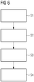
- Fig. 6 shows a schematic flow-diagram of an exemplary method for installing an offshore foundation structure 100 (see Fig. 1 - 5 ).
- the offshore foundation structure 100 may be implemented as described with reference to one of Figs. 1 - 4 .
- a foundation member 110 (see Fig. 1 - 5 ) and a fixation member 120 (see Fig. 1 - 5 ) are pre-assembled. This is performed in a harbor, for example.
- a second step S2 the pre-assembly is carried to the offshore installation site using a vessel (e.g. jack-up vessel), for example.
- a vessel e.g. jack-up vessel
- the pre-assembly is lowered into the sea and placed on the seabed 105.
- the fixation member 122 is screwed into the seabed 105 by turning a screw portion 122 of the fixation member 120. Screwing can be done using a drive unit 130 arranged on the vessel or on or inside the fixation member 122, for example.
- the drive unit 130 may be connected (attached) to the screw portion 122 using extension means 132 (when the drive unit 130 is arranged on the vessel) or directly (when the drive unit 130 is arranged on or inside the fixation member 122 or elsewhere on the foundation structure 100).
- the drive unit 130 may be disconnected (detached) from the screw portion 122 and removed from the installation site and/or used again for screwing a screw portion 122 of another foundation structure 100 into the seabed (after step S3 or step S4 for example) at another installation site.
- a fourth step S4 the fixation member 120 is fastened to the foundation member 110.
- the screwing is performed until a fitting portion 124 of the fixation member 120 engages with a corresponding fitting portion 114 on the foundation member 110, forming a press fit.
- fastening may be performed by other means, such as welding, bolting or screwing.
Landscapes
- Engineering & Computer Science (AREA)
- Life Sciences & Earth Sciences (AREA)
- General Life Sciences & Earth Sciences (AREA)
- Mining & Mineral Resources (AREA)
- Paleontology (AREA)
- Civil Engineering (AREA)
- General Engineering & Computer Science (AREA)
- Structural Engineering (AREA)
- Foundations (AREA)
- Wind Motors (AREA)
Abstract
a foundation member (110) configured for being installed on the seabed (105) and for supporting the offshore foundation (200), and
a fixation member (120) configured for being fixed in the seabed (105) for installing the foundation member (110), characterized in that
the fixation member (120) has a screw portion (122) for screwing the fixation member (120) into the seabed (105).
Description
- The present invention relates to an offshore foundation structure, an offshore foundation with such an offshore foundation structure and a method for installing an offshore foundation structure.
- Common offshore foundations, for example for supporting a wind turbine, typically comprise a number of posts or poles that are fixed in the seabed. Depending on the properties of the seabed at the installation site, various known techniques for fixing the posts in the seabed are employed.
- For example,
EP 2 558 647 B1 describes an offshore foundation structure comprising a hollow foundation member and a pile arranged inside the hollow foundation member. The pile is driven into the seabed by hammering means. - It is an objective of this invention to suggest an improved offshore foundation structure.
- According to a first aspect, an offshore foundation structure for supporting an offshore foundation, in particular an offshore foundation for a wind turbine, is suggested. The offshore foundation structure comprises a foundation member configured for being installed on the seabed and for supporting the offshore foundation, and a fixation member configured for being fixed in the seabed for installing the foundation member. The fixation member has a screw portion for screwing the fixation member into the seabed.
- This offshore foundation structure has the advantage that it can be installed by screwing the fixation member into the seabed. Screwing is a technique that allows fast installation, thus the time needed for installing the offshore foundation structure can be reduced. Since the equipment needed for installing the offshore foundation structure, such as specific vessels, are expensive, this can further reduce costs for installing the offshore foundation structure. Also, tools for screwing are readily available, which can help to reduce the costs even further.
- The offshore foundation structure may be denoted as leg, post or pole in the following. The offshore foundation structure comprises at least the foundation member and the fixation member. The foundation member serves as the actual pole, extending essentially above the seabed when installed. The fixation member serves as an anchor for the foundation member, securely fixing the foundation member to the seabed, and is essentially buried in the seabed when installed. "Essentially above" or "essentially buried" means that there may be a small portion of the respective member that is not above the seabed or is not buried in the seabed. A small portion is, for example, a fraction less than 50% of a total length of the respective member.
- Preferably, the foundation member has a length that is individually determined depending on the installation site of the post, such that a top end of the foundation member has a predefined height above the seabed or above the water level. Preferably, the fixation member has a length that is individually determined depending on the installation site, particularly as a function of the properties of the seabed. Further, not only the length, but also a diameter and/or a configuration of other individual features are selected such that the fixation member provides a stable and secure anchor for the foundation member.
- The fixation member comprises a screw portion, which is in particular located at a tip of the fixation member. The screw portion is configured for screwing the fixation member into the seabed. The screw portion may comprise several sections having various configurations, such as variable diameter, thread specification and/or material. Preferably, the screw portion is adapted for the particular kind of the seabed at an offshore installation site.
- The screw portion may comprise a drill portion configured for drilling a hole into the seabed for receiving the fixation member. Preferably, the screw portion comprises a hard tip that is sufficiently robust for being screwed into rock.
- The suggested offshore foundation structure facilitates a quick and easy installation or establishment of an offshore foundation. In particular, most pre-preparation steps can be carried out at land, while preparation steps at an offshore installation site may be reduced to a minimum. Particularly, there is no necessity of preparing a specific foundation in the seabed, since the offshore foundation structure can be adapted to the specific parameters or properties of the installation site and/or the seabed of the installation site before the installation.
- According to an embodiment, the foundation member has a tubular hollow portion and the fixation member is at least partially arranged inside the tubular hollow portion of the foundation member.
- This embodiment has several advantages. First, the fixation member may be arranged inside the tubular hollow portion of the foundation member for transportation, for example, simplifying transport. This can further reduce the cost for installing the post. Second, the foundation member is lighter and more stable at the same time in this configuration. This helps to reduce the amount of raw material needed for manufacturing of the foundation member. Third, the foundation member can serve as a guidance rail for screwing of the fixation member into the seabed. This is particularly advantageous, because it can reduce the number of tools needed for installing the post, thus further reducing the cost.
- In embodiments, the fixation member may be fully arranged inside the tubular hollow portion of the foundation member before being screwed into the seabed.
- According to a further embodiment, the foundation member has a fastening portion configured for being fastened to a corresponding fastening portion on the fixation member.
- The allows secure fastening of the foundation member to the fixation member after the fixation member is screwed into the seabed. Thus, a stability of the offshore foundation structure can be increased.
- According to a further embodiment, the foundation member and the fixation member are configured for being fitted, welded, bolted and/or screwed together.
- For example, an interference fit or press fit, in particular a conical interference fit, may be employed for fitting the foundation member and the fixation member together.
- In the case of the screwing portion, the foundation member preferably comprises a number of through holes and the fixation member comprises a corresponding number of screw holes or vice-versa, wherein a screw is driven through each through hole and tightly screwed into the screw hole, thus securely fixing the fixation member to the foundation member.
- According to a further embodiment, the offshore foundation structure comprises a drive unit configured for screwing the fixation member into the seabed by turning the screw portion.
- The drive unit may comprise an engine that is driven by electricity or by fossil fuels. The drive unit may be configured to turn the screw portion via a specific driving shaft. In embodiments, the fixation member and the screw portion are integrally formed and the drive unit may be attached to the fixation member directly. Preferably, the drive unit is configured for providing a torque that is sufficient for screwing the fixation member into the seabed, even when the seabed is rock, in one round, that is, without changing a turning direction during screwing. A counter-torque for screwing of the fixation member is preferably provided by a vessel floating at the installation site during installation. The counter-torque may also be provided by a temporary structure, such as an anchor, or by the foundation member.
- According to a further embodiment, the drive unit is arranged inside the tubular hollow portion.
- This embodiment allows a very compact configuration, thus simplifying transport of the offshore foundation structure to the installation site. During screwing, the drive unit is, for example, rotationally fixed to the foundation member, such that the counter-torque may be provided by holding the foundation member fixed.
- According to a further embodiment, the drive unit comprises an extension means configured for transferring a torque generated by the drive unit onto the screw portion.
- This embodiment allows that the drive unit may be arranged outside of the foundation member, for example on top of the foundation member or on a vessel. Further, usage of the drive unit is flexible in the sense that it can be used for a variety of different fixation members.
- For example, the extension means is a driving shaft, which may be relatively cheap in production. Such a shaft may remain inside a tubular hollow portion of the foundation member after screwing the fixation member into the seabed.
- According to a further embodiment, the screw portion further comprises a drill portion.
- This embodiment is advantageous in that it allows to drill a hole into the seabed while at the same time screwing the fixation member into the drilled hole in the seabed. Preferably, the drill portion has a sharp tip and specific tools for drilling a hole into rock or the like. This embodiment allows the fixation member to be screwed into the seabed even when the seabed consists of rock or a similarly tough or hard material.
- According to a further embodiment, the fixation member is made from metal.
- Preferably, the fixation member is made from steel, particularly stainless steel or other kinds of steel which can resist seawater.
- In a further embodiment, the fixation member is implemented as a screw. That is, the screw portion extends along the larger part of the fixation member. Particularly, the screw portion extends fully along the part of the fixation member that is buried in the seabed after screwing. The fixation member may comprise a screw head, which may be employed for fastening of the fixation member to the foundation member and/or for attaching the drive unit and turning the fixation member. Preferably, the fixation member is integrally formed in this embodiment.
- In this embodiment, the fixation member can be unscrewed from the seabed, for example after an end-of-life of an offshore installation. This allows to restore the original state of the seabed at the installation site, such that an environmental impact can be reduced.
- According to a second aspect of the invention, an offshore foundation, in particular for a wind turbine, comprising multiple offshore foundation structures according to the first aspect is suggested.
- Preferably, the offshore foundation comprises three or four of the offshore foundation structures. This provides a high stability without using an unnecessary large number of the offshore foundation structures.
- According to a third aspect, a method for installing an offshore foundation structure for supporting an offshore foundation, in particular an offshore foundation for a wind turbine, is suggested. The method comprises screwing of a fixation member into the seabed by turning a screw portion of the fixation member.
- The method is preferably employed with an offshore foundation structure according to the first aspect.
- This method has the advantage that the offshore foundation member can be installed with relatively simple tools, readily available tools and in a relatively short time. That is, the method can save both time and money, because the tools and/or vessels needed for installing are less complex and/or less expensive than the tools or vessels required in other ways of installing an offshore foundation structure.
- According to an embodiment, the method further comprises pre-assembling the fixation member with a foundation member configured for being installed on the seabed and for supporting the offshore foundation, and transferring the pre-assembly to an offshore installation site.
- Preferably, the pre-assembling is performed on land, for example in a harbor or in a shipyard. By referring to the pre-assembly, the pre-assembled fixation member with the foundation member are denoted. Pre-assembling may comprise fixing the fixation member on the foundation member or vice versa in a manner that allows the fixation member to be screwed into the seabed. Preferably, the foundation member further serves as a guidance rail for the screwing of the fixation member.
- By preparing the pre-assembly on land, a time needed for installing the offshore foundation structure at the offshore installation site can be reduced significantly. Further, conditions for pre-assembling at a pre-assembly site on land can be much better, in particular concerning weather conditions and a stable ground.
- Preferably, a drive unit employed for turning the screw portion for screwing the fixation member into the seabed is also attached in the pre-assembling step. Then, the pre-assembly is ready to be installed without any further preparations necessary at the offshore installation site. That is, all that has to be done at the offshore installation site is to lower the pre-assembly on the desired spot on the seabed and start the drive unit.
- According to a further embodiment, the method further comprises fastening of the foundation member to the fixation member.
- This allows a stable and long-living connection between the fixation member and the foundation member.
- According to a further embodiment, the method further comprises attaching a drive unit for screwing the fixation member into the seabed, in particular during the pre-assembly step, and
detaching the drive unit from the fixation member after the fixation member has been screwed into the seabed. - This embodiment has the advantage that the drive unit can be used multiple times.
- Further possible implementations or alternative solutions of the invention also encompass combinations - that are not explicitly mentioned herein - of features described above or below with regard to the embodiments. The person skilled in the art may also add individual or isolated aspects and features to the most basic form of the invention.
- Further embodiments, features and advantages of the present invention will become apparent from the subsequent description and dependent claims, taken in conjunction with the accompanying drawings, in which:
- Fig. 1
- shows a schematic view of a first example of an off-shore foundation structure;
- Fig. 2
- shows a further schematic view of the first example of an offshore foundation structure;
- Fig. 3
- shows a schematic view of a second example of an offshore foundation structure;
- Fig. 4
- shows a schematic view of a third example of an off-shore foundation structure;
- Fig. 5
- shows a schematic perspective view of an offshore foundation carrying a wind turbine; and
- Fig. 6
- shows a schematic flow-diagram of an example of a method for installing an offshore foundation structure.
- In the figures, the same reference numerals designate the same or equivalent elements.
-
Fig. 1 shows a schematic view of a first example of anoffshore foundation structure 100 comprising afoundation member 110 and afixation member 120. InFig. 1 , theoffshore foundation structure 100 is shown in a state before it is installed. InFig. 2 , theoffshore foundation structure 100 is shown after being installed at an offshore installation site. - The
foundation member 110 of this example has a tubularhollow portion 112 in which thefixation member 120 is arranged before installation. Thefoundation member 110 is placed on a desired installation position on theseabed 105. Thefoundation member 110 is oriented such that afastening portion 114 inside thefoundation member 110 is arranged on the side towards theseabed 105. The upper side of thefoundation member 110, which is above the water surface 106 (sea level), may have engagement means (not shown) for engaging with a construction of an offshore foundation, such as a tower or the like. Thefoundation member 110 is open at the top so that a tool for screwing thefixation member 120 can reach anengagement portion 128 formed in an upper portion of thefixation member 120. Thefoundation member 110 also has an opening at the lower end that is directed towards theseabed 105 through which thefixation member 120 can extend into theseabed 105. However, the lower end opening is smaller than an upper portion of thefixation member 120, so that thefixation member 120 cannot fully escape the tubularhollow portion 112 of thefoundation member 110. - The
fixation member 120 is arranged inside thefoundation member 110 before installation and comprises ascrew portion 122, afastening portion 124 and anengagement portion 128. Thefixation member 120 is implemented integrally as a screw. In other embodiments, thescrew portion 122 may be rotatable independently from other elements of thefixation member 120, such as thefastening portion 124, for example. The upper portion comprising thefastening portion 124 and theengagement portion 128 may be called screw head. Thescrew portion 122 extends along most of the length of thefixation member 120 and it preferably has a sharp tip on its front end, which is directed towards theseabed 105. Theengagement portion 128 is configured for engaging with a tool (not shown) for turning thescrew portion 122. Thefoundation member 110 serves as a guidance rail for thefixation member 120 when it is screwed into theseabed 105, which simplifies the installation process. -
Fig. 2 shows theoffshore foundation structure 100 as described referring toFig. 1 in an installed state. Thefixation member 120 is screwed into theseabed 105. For example, a drive unit 130 (seeFig. 3 ) was employed for turning thescrew portion 122 for screwing thefixation member 120 into theseabed 105. Thescrew portion 122 drags itself and thefixation member 120 into theseabed 105 when it is rotated in the correct direction. Thus, when thefixation member 120 is screwed into theseabed 105 sufficiently deep, thefastening portion 124 of thefixation member 120 engages with thefastening portion 114 of thefoundation member 110. In this case, thefastening portions fixation member 120. Thefixation member 120 is screwed into theseabed 105 until a predetermined pressing force between thefoundation member 110 and thefixation member 120 is reached. The predetermined pressing force is set such that theoffshore foundation structure 100 is securely fixed in theseabed 105 for the desired use of theoffshore foundation structure 100. -
Fig. 3 shows a schematic view of a second example of anoffshore foundation structure 100. InFig. 3 , theoffshore foundation structure 100 is shown in an intermediate state during installation. - The
foundation member 110 comprises a tubularhollow portion 112 inside which thefixation member 120 is arranged. In this example, thefoundation member 110 comprises afoot 116 that is arranged for creating a large contact area of thefoundation member 110 on theseabed 105, so that a high pressing force can be applied by thefixation member 120 on thefoundation member 110. In this example, thefoundation member 110 and thefoot 116 are arranged such that thefoundation member 110 is tilted relative to theseabed 105. This allows to establish an offshore foundation 200 (seeFig. 5 ) in the manner of a tripod, which is a very stable construction due to the large base. On a lower end of thefoundation member 110, afastening portion 114 is formed. In this example, thefastening portion 114 comprises a pressing area configured for engaging with a corresponding area of thefixation member 120, and it comprises holes for bolts or screws. Fastening is explained referring toFig. 4 below. - The
fixation member 120 in this example comprises ascrew portion 122, afastening portion 124, adrill portion 126 and anengagement portion 128. Thedrill portion 126 is arranged on the tip of thefixation member 120 and is configured for drilling a hole into theseabed 105. For example, theseabed 105 consists of rock. Then, thedrill portion 126 provides a channel or hole for thescrew portion 122. - The
screw portion 122 is embodied as an external thread which is designed such that a diameter of the thread increases from the tip to the upper end, as is shown inFig. 3 . This has the advantage that a strength of the anchor provided by thefixation member 120 may be increased, because each section of thescrew portion 122 establishes a firm grip or engagement with theseabed 105. At the upper end of thefixation member 120, thefastening portion 124 is arranged. Here, thefastening portion 124 comprises a flat lower surface and a number of bolt-holes or screw-holes. Fastening is explained with reference toFig. 4 below. - On the top side, the
engagement portion 128 is arranged. Here, theengagement portion 128 is currently engaged with an extension means 132 of adrive unit 130. Thedrive unit 130 is embodied as a drilling machine, for example, and is arranged above thewater surface 106. Thedrive unit 130 may be arranged on a structure (not shown) on thefoundation member 110 or on a vessel (not shown), for example. The extension means 132 are embodied as a shaft for rotating the screw portion 122 (functioning also as a drill bit in this example) or thewhole fixation member 120. Use of theshaft 132 may be advantageous since thedrive unit 130 can stay outside of thefoundation member 110, thus it may be constructed with less constraints. Further, theshaft 132 may be implemented with a flexible joint, which allows a higher flexibility. After thefixation member 120 is screwed (drilled) into theseabed 105, thedrive unit 130 is preferably detached from theengagement portion 128. Theshaft 132 can be left inside the tubularhollow portion 112 or may be removed, as desired. - Advantageously, the described
offshore foundation structure 100 may be pre-assembled on land. Particularly, thefixation member 120 may be placed inside the tubularhollow portion 112 of thefoundation member 110 and thedrive unit 130 may be attached to theengagement portion 128. This pre-assembly is then transported, for example by floats, to the offshore installation site. There, the pre-assembly is lowered to theseabed 105 and thedrive unit 130 is switched on. Thefixation member 120 will then be screwed into theseabed 105 by thescrew portion 122. Overall, this is a very efficient and fast way of installing theoffshore foundation structure 100. -
Fig. 4 shows a schematic view of a third example of anoffshore foundation structure 100. Theoffshore foundation structure 100 shown here may have all the features described above with reference toFigs. 1 - 3 . Here, the fastening of thefoundation member 110 and thefixation member 120 using bolts and/or screws is explained. Thefixation member 120 is fully screwed into theseabed 105. In this example, thefoundation member 110 and thefixation member 120 comprisefastening portions Fig. 3 . Thefastening portion 124 of thefixation member 120 has a flat surface that presses against a respective flat surface that is part of thefastening portion 114 of thefoundation member 110. In this position,bolts 118 andscrews 119 are driven through respective through holes that form part of thefastening portion 114 of thefoundation member 110. Thebolts 118 andscrews 119 penetrate into corresponding bolt holes or screw holes that form part of thefastening portion 124 of thefixation member 120. Thus, thefastening portions foundation member 110 and thefixation member 120 is strong and secure. If desired, thebolts 118 and/orscrews 119 may be welded to thefoundation member 110 so that loosening is prevented. -
Fig. 5 shows a schematic perspective view of anoffshore foundation 200 carrying awind turbine 300. Theoffshore foundation 200 comprises threeoffshore foundation structures 100, which form a tripod in this example. For example, theoffshore foundation structures 100 may be implemented as described with reference to one ofFigs. 1 - 4 . Theoffshore foundation 200 provides a stable platform that can host a variety of apparatuses and/or installations, not only awind turbine 300 as shown in this example, but also an oil platform, a scientific platform and/or other offshore installations. -
Fig. 6 shows a schematic flow-diagram of an exemplary method for installing an offshore foundation structure 100 (seeFig. 1 - 5 ). For example, theoffshore foundation structure 100 may be implemented as described with reference to one ofFigs. 1 - 4 . - In a first step S1, a foundation member 110 (see
Fig. 1 - 5 ) and a fixation member 120 (seeFig. 1 - 5 ) are pre-assembled. This is performed in a harbor, for example. - In a second step S2, the pre-assembly is carried to the offshore installation site using a vessel (e.g. jack-up vessel), for example. When the installation site is reached, the pre-assembly is lowered into the sea and placed on the
seabed 105. - In a third step S3, the
fixation member 122 is screwed into theseabed 105 by turning ascrew portion 122 of thefixation member 120. Screwing can be done using adrive unit 130 arranged on the vessel or on or inside thefixation member 122, for example. To this end, thedrive unit 130 may be connected (attached) to thescrew portion 122 using extension means 132 (when thedrive unit 130 is arranged on the vessel) or directly (when thedrive unit 130 is arranged on or inside thefixation member 122 or elsewhere on the foundation structure 100). Thedrive unit 130 may be disconnected (detached) from thescrew portion 122 and removed from the installation site and/or used again for screwing ascrew portion 122 of anotherfoundation structure 100 into the seabed (after step S3 or step S4 for example) at another installation site. - In a fourth step S4, the
fixation member 120 is fastened to thefoundation member 110. For example, the screwing is performed until afitting portion 124 of thefixation member 120 engages with a correspondingfitting portion 114 on thefoundation member 110, forming a press fit. However, fastening may be performed by other means, such as welding, bolting or screwing. - Although the present invention has been described in accordance with preferred embodiments, it is obvious for the person skilled in the art that modifications are possible in all embodiments.
Claims (14)
- An offshore foundation structure (100) for supporting an offshore foundation (200), in particular an offshore foundation (200) for a wind turbine (300), comprising
a foundation member (110) configured for being installed on the seabed (105) and for supporting the offshore foundation (200), and
a fixation member (120) configured for being fixed in the seabed (105) for installing the foundation member (110), characterized in that
the fixation member (120) has a screw portion (122) for screwing the fixation member (120) into the seabed (105). - The offshore foundation structure according to claim 1, wherein the foundation member (110) has a tubular hollow portion (112) and the fixation member (120) is at least partially arranged inside the tubular hollow portion (112) of the foundation member (110).
- The offshore foundation structure according to claim 1 or 2, wherein the foundation member (110) has a fastening portion (114) configured for being fastened to a corresponding fastening portion (124) on the fixation member (120).
- The offshore foundation structure according to claim 3, wherein the foundation member (110) and the fixation member (120) are configured for being fitted, welded, bolted and/or screwed together.
- The offshore foundation structure according to any one of claims 1 to 4, comprising a drive unit (130) configured for screwing the fixation member (120) into the seabed (105) by turning the screw portion (122).
- The offshore foundation structure according to claim 5, wherein the drive unit (130) is arranged inside the tubular hollow portion (112).
- The offshore foundation structure according to any one of claims 1 to 6, wherein the drive unit (130) comprises an extension means (132) configured for transferring a torque generated by the drive unit (130) to the screw portion (122).
- The offshore foundation structure according to any one of claims 1 to 7, wherein the screw portion (122) further comprises a drill portion (126).
- The offshore foundation structure according to any one of claims 1 to 8, wherein the fixation member (120) is made from metal.
- An offshore foundation (200), in particular for a wind turbine (300), comprising multiple offshore foundation structures (100) according to any one of claims 1 to 9.
- A method for installing an offshore foundation structure (100) for supporting an offshore foundation (200), in particular an offshore foundation (200) for a wind turbine (300), wherein a fixation member (120) is screwed into the seabed (105) by turning a screw portion (122) of the fixation member (120) .
- The method according to claim 11, further comprising:pre-assembling the fixation member (120) with a foundation member (110) configured for being installed on the seabed (105) and for supporting the offshore foundation (200), andtransferring the pre-assembly to an offshore installation site.
- The method according to claim 11 or 12, wherein the foundation member (110) is fastened to the fixation member (120).
- The method according to any one of claims 11 to 13, further comprising:attaching a drive unit (130) for screwing the fixation member (120) into the seabed (105), in particular during the pre-assembly step, anddetaching the drive unit (130) from the fixation member (120) after the fixation member (120) has been screwed into the seabed (105).
Priority Applications (1)
| Application Number | Priority Date | Filing Date | Title |
|---|---|---|---|
| EP19153089.8A EP3686348B1 (en) | 2019-01-22 | 2019-01-22 | Offshore foundation structure, offshore foundation with such offshore foundation structure and method for installing an offshore foundation structure |
Applications Claiming Priority (1)
| Application Number | Priority Date | Filing Date | Title |
|---|---|---|---|
| EP19153089.8A EP3686348B1 (en) | 2019-01-22 | 2019-01-22 | Offshore foundation structure, offshore foundation with such offshore foundation structure and method for installing an offshore foundation structure |
Publications (2)
| Publication Number | Publication Date |
|---|---|
| EP3686348A1 true EP3686348A1 (en) | 2020-07-29 |
| EP3686348B1 EP3686348B1 (en) | 2024-07-17 |
Family
ID=65200653
Family Applications (1)
| Application Number | Title | Priority Date | Filing Date |
|---|---|---|---|
| EP19153089.8A Active EP3686348B1 (en) | 2019-01-22 | 2019-01-22 | Offshore foundation structure, offshore foundation with such offshore foundation structure and method for installing an offshore foundation structure |
Country Status (1)
| Country | Link |
|---|---|
| EP (1) | EP3686348B1 (en) |
Citations (6)
| Publication number | Priority date | Publication date | Assignee | Title |
|---|---|---|---|---|
| WO2011147480A2 (en) * | 2010-05-28 | 2011-12-01 | Siemens Aktiengesellschaft | Offshore foundation structure, offshore foundation using such a structure and method of establishing an offshore foundation |
| US20130255169A1 (en) * | 2012-03-30 | 2013-10-03 | Allan P. Henderson | Cementitious foundation cap with post-tensioned helical anchors |
| KR101656694B1 (en) * | 2015-04-23 | 2016-09-13 | (주)동명기술공단종합건축사사무소 | Submarine structure construction method using rotation type head fixing apparatus |
| CN205857223U (en) * | 2016-06-21 | 2017-01-04 | 中国电建集团华东勘测设计研究院有限公司 | A kind of spiral straight pile-type offshore wind turbine bearing platform type base structure |
| EP3203065A1 (en) * | 2016-02-02 | 2017-08-09 | Dywidag Sistemas Constructivos, S.A. | Wind tower connection system |
| CN206418517U (en) * | 2016-12-30 | 2017-08-18 | 西安建筑科技大学 | A kind of prefabricated anchor foundation for frozen soil foundation |
-
2019
- 2019-01-22 EP EP19153089.8A patent/EP3686348B1/en active Active
Patent Citations (7)
| Publication number | Priority date | Publication date | Assignee | Title |
|---|---|---|---|---|
| WO2011147480A2 (en) * | 2010-05-28 | 2011-12-01 | Siemens Aktiengesellschaft | Offshore foundation structure, offshore foundation using such a structure and method of establishing an offshore foundation |
| EP2558647B1 (en) | 2010-05-28 | 2017-11-01 | Siemens Aktiengesellschaft | Offshore foundation structure, offshore foundation using such a structure and method of establishing an offshore foundation |
| US20130255169A1 (en) * | 2012-03-30 | 2013-10-03 | Allan P. Henderson | Cementitious foundation cap with post-tensioned helical anchors |
| KR101656694B1 (en) * | 2015-04-23 | 2016-09-13 | (주)동명기술공단종합건축사사무소 | Submarine structure construction method using rotation type head fixing apparatus |
| EP3203065A1 (en) * | 2016-02-02 | 2017-08-09 | Dywidag Sistemas Constructivos, S.A. | Wind tower connection system |
| CN205857223U (en) * | 2016-06-21 | 2017-01-04 | 中国电建集团华东勘测设计研究院有限公司 | A kind of spiral straight pile-type offshore wind turbine bearing platform type base structure |
| CN206418517U (en) * | 2016-12-30 | 2017-08-18 | 西安建筑科技大学 | A kind of prefabricated anchor foundation for frozen soil foundation |
Also Published As
| Publication number | Publication date |
|---|---|
| EP3686348B1 (en) | 2024-07-17 |
Similar Documents
| Publication | Publication Date | Title |
|---|---|---|
| US6352391B1 (en) | Piering device having a threaded shaft and helical plate | |
| US6817810B2 (en) | Piering device with adjustable helical plate | |
| US6665990B1 (en) | High-tension high-compression foundation for tower structures | |
| US6368021B1 (en) | Pile and method for installing same | |
| EP1567727B1 (en) | Mounting of offshore structures | |
| US6682267B1 (en) | Piering device with adjustable helical plate | |
| EP2042659B1 (en) | Anchor post | |
| US7377723B2 (en) | Systems and methods for the installation of earth anchors | |
| EP1741928B1 (en) | System and method for installing a wind turbine at an offshore location | |
| WO2018129471A1 (en) | Modular offshore wind turbine foundation and modular substructure with suction caissons | |
| EP1815146B1 (en) | Offshore structure support and foundation for use with a wind turbine and an associated method of assembly | |
| EP4211349B1 (en) | An offshore wind farm foundation | |
| WO2007033413A1 (en) | Ground anchor | |
| WO2009157775A1 (en) | Stayed connection for wind turbine | |
| EP3307954A1 (en) | Monopile foundation for an offshore tower structure | |
| KR20230139102A (en) | Underground anchor pile for a solar panel and the construction structure | |
| CA1119823A (en) | Precast concrete threaded piling system | |
| EP3686348B1 (en) | Offshore foundation structure, offshore foundation with such offshore foundation structure and method for installing an offshore foundation structure | |
| JP2011080195A (en) | Anchor device and method of installing anchor | |
| KR102176004B1 (en) | Rotating type offshore structure and construction method, and power generation system using the same | |
| AU2015261689A1 (en) | Screw Pile | |
| CN202989913U (en) | Pointless spiral pile | |
| KR20220038515A (en) | Fixtures and installation methods | |
| EP2558647B1 (en) | Offshore foundation structure, offshore foundation using such a structure and method of establishing an offshore foundation | |
| US20100310321A1 (en) | Pile for Foundation |
Legal Events
| Date | Code | Title | Description |
|---|---|---|---|
| PUAI | Public reference made under article 153(3) epc to a published international application that has entered the european phase |
Free format text: ORIGINAL CODE: 0009012 |
|
| STAA | Information on the status of an ep patent application or granted ep patent |
Free format text: STATUS: THE APPLICATION HAS BEEN PUBLISHED |
|
| AK | Designated contracting states |
Kind code of ref document: A1 Designated state(s): AL AT BE BG CH CY CZ DE DK EE ES FI FR GB GR HR HU IE IS IT LI LT LU LV MC MK MT NL NO PL PT RO RS SE SI SK SM TR |
|
| AX | Request for extension of the european patent |
Extension state: BA ME |
|
| STAA | Information on the status of an ep patent application or granted ep patent |
Free format text: STATUS: REQUEST FOR EXAMINATION WAS MADE |
|
| 17P | Request for examination filed |
Effective date: 20210129 |
|
| RBV | Designated contracting states (corrected) |
Designated state(s): AL AT BE BG CH CY CZ DE DK EE ES FI FR GB GR HR HU IE IS IT LI LT LU LV MC MK MT NL NO PL PT RO RS SE SI SK SM TR |
|
| STAA | Information on the status of an ep patent application or granted ep patent |
Free format text: STATUS: EXAMINATION IS IN PROGRESS |
|
| 17Q | First examination report despatched |
Effective date: 20220706 |
|
| GRAP | Despatch of communication of intention to grant a patent |
Free format text: ORIGINAL CODE: EPIDOSNIGR1 |
|
| STAA | Information on the status of an ep patent application or granted ep patent |
Free format text: STATUS: GRANT OF PATENT IS INTENDED |
|
| INTG | Intention to grant announced |
Effective date: 20240307 |
|
| GRAS | Grant fee paid |
Free format text: ORIGINAL CODE: EPIDOSNIGR3 |
|
| GRAA | (expected) grant |
Free format text: ORIGINAL CODE: 0009210 |
|
| STAA | Information on the status of an ep patent application or granted ep patent |
Free format text: STATUS: THE PATENT HAS BEEN GRANTED |
|
| AK | Designated contracting states |
Kind code of ref document: B1 Designated state(s): AL AT BE BG CH CY CZ DE DK EE ES FI FR GB GR HR HU IE IS IT LI LT LU LV MC MK MT NL NO PL PT RO RS SE SI SK SM TR |
|
| REG | Reference to a national code |
Ref country code: CH Ref legal event code: EP |
|
| REG | Reference to a national code |
Ref country code: DE Ref legal event code: R096 Ref document number: 602019055243 Country of ref document: DE |
|
| REG | Reference to a national code |
Ref country code: IE Ref legal event code: FG4D |
|
| REG | Reference to a national code |
Ref country code: LT Ref legal event code: MG9D |
|
| REG | Reference to a national code |
Ref country code: NL Ref legal event code: MP Effective date: 20240717 |
|
| PG25 | Lapsed in a contracting state [announced via postgrant information from national office to epo] |
Ref country code: PT Free format text: LAPSE BECAUSE OF FAILURE TO SUBMIT A TRANSLATION OF THE DESCRIPTION OR TO PAY THE FEE WITHIN THE PRESCRIBED TIME-LIMIT Effective date: 20241118 |
|
| REG | Reference to a national code |
Ref country code: AT Ref legal event code: MK05 Ref document number: 1704247 Country of ref document: AT Kind code of ref document: T Effective date: 20240717 |
|
| PG25 | Lapsed in a contracting state [announced via postgrant information from national office to epo] |
Ref country code: NL Free format text: LAPSE BECAUSE OF FAILURE TO SUBMIT A TRANSLATION OF THE DESCRIPTION OR TO PAY THE FEE WITHIN THE PRESCRIBED TIME-LIMIT Effective date: 20240717 |
|
| PG25 | Lapsed in a contracting state [announced via postgrant information from national office to epo] |
Ref country code: PT Free format text: LAPSE BECAUSE OF FAILURE TO SUBMIT A TRANSLATION OF THE DESCRIPTION OR TO PAY THE FEE WITHIN THE PRESCRIBED TIME-LIMIT Effective date: 20241118 Ref country code: NL Free format text: LAPSE BECAUSE OF FAILURE TO SUBMIT A TRANSLATION OF THE DESCRIPTION OR TO PAY THE FEE WITHIN THE PRESCRIBED TIME-LIMIT Effective date: 20240717 |
|
| PG25 | Lapsed in a contracting state [announced via postgrant information from national office to epo] |
Ref country code: NO Free format text: LAPSE BECAUSE OF FAILURE TO SUBMIT A TRANSLATION OF THE DESCRIPTION OR TO PAY THE FEE WITHIN THE PRESCRIBED TIME-LIMIT Effective date: 20241017 |
|
| PG25 | Lapsed in a contracting state [announced via postgrant information from national office to epo] |
Ref country code: PL Free format text: LAPSE BECAUSE OF FAILURE TO SUBMIT A TRANSLATION OF THE DESCRIPTION OR TO PAY THE FEE WITHIN THE PRESCRIBED TIME-LIMIT Effective date: 20240717 Ref country code: GR Free format text: LAPSE BECAUSE OF FAILURE TO SUBMIT A TRANSLATION OF THE DESCRIPTION OR TO PAY THE FEE WITHIN THE PRESCRIBED TIME-LIMIT Effective date: 20241018 Ref country code: FI Free format text: LAPSE BECAUSE OF FAILURE TO SUBMIT A TRANSLATION OF THE DESCRIPTION OR TO PAY THE FEE WITHIN THE PRESCRIBED TIME-LIMIT Effective date: 20240717 |
|
| PG25 | Lapsed in a contracting state [announced via postgrant information from national office to epo] |
Ref country code: BG Free format text: LAPSE BECAUSE OF FAILURE TO SUBMIT A TRANSLATION OF THE DESCRIPTION OR TO PAY THE FEE WITHIN THE PRESCRIBED TIME-LIMIT Effective date: 20240717 |
|
| PG25 | Lapsed in a contracting state [announced via postgrant information from national office to epo] |
Ref country code: LV Free format text: LAPSE BECAUSE OF FAILURE TO SUBMIT A TRANSLATION OF THE DESCRIPTION OR TO PAY THE FEE WITHIN THE PRESCRIBED TIME-LIMIT Effective date: 20240717 |
|
| PG25 | Lapsed in a contracting state [announced via postgrant information from national office to epo] |
Ref country code: IS Free format text: LAPSE BECAUSE OF FAILURE TO SUBMIT A TRANSLATION OF THE DESCRIPTION OR TO PAY THE FEE WITHIN THE PRESCRIBED TIME-LIMIT Effective date: 20241117 Ref country code: AT Free format text: LAPSE BECAUSE OF FAILURE TO SUBMIT A TRANSLATION OF THE DESCRIPTION OR TO PAY THE FEE WITHIN THE PRESCRIBED TIME-LIMIT Effective date: 20240717 |
|
| PG25 | Lapsed in a contracting state [announced via postgrant information from national office to epo] |
Ref country code: HR Free format text: LAPSE BECAUSE OF FAILURE TO SUBMIT A TRANSLATION OF THE DESCRIPTION OR TO PAY THE FEE WITHIN THE PRESCRIBED TIME-LIMIT Effective date: 20240717 |
|
| PG25 | Lapsed in a contracting state [announced via postgrant information from national office to epo] |
Ref country code: ES Free format text: LAPSE BECAUSE OF FAILURE TO SUBMIT A TRANSLATION OF THE DESCRIPTION OR TO PAY THE FEE WITHIN THE PRESCRIBED TIME-LIMIT Effective date: 20240717 Ref country code: RS Free format text: LAPSE BECAUSE OF FAILURE TO SUBMIT A TRANSLATION OF THE DESCRIPTION OR TO PAY THE FEE WITHIN THE PRESCRIBED TIME-LIMIT Effective date: 20241017 |
|
| PG25 | Lapsed in a contracting state [announced via postgrant information from national office to epo] |
Ref country code: RS Free format text: LAPSE BECAUSE OF FAILURE TO SUBMIT A TRANSLATION OF THE DESCRIPTION OR TO PAY THE FEE WITHIN THE PRESCRIBED TIME-LIMIT Effective date: 20241017 Ref country code: PL Free format text: LAPSE BECAUSE OF FAILURE TO SUBMIT A TRANSLATION OF THE DESCRIPTION OR TO PAY THE FEE WITHIN THE PRESCRIBED TIME-LIMIT Effective date: 20240717 Ref country code: NO Free format text: LAPSE BECAUSE OF FAILURE TO SUBMIT A TRANSLATION OF THE DESCRIPTION OR TO PAY THE FEE WITHIN THE PRESCRIBED TIME-LIMIT Effective date: 20241017 Ref country code: LV Free format text: LAPSE BECAUSE OF FAILURE TO SUBMIT A TRANSLATION OF THE DESCRIPTION OR TO PAY THE FEE WITHIN THE PRESCRIBED TIME-LIMIT Effective date: 20240717 Ref country code: IS Free format text: LAPSE BECAUSE OF FAILURE TO SUBMIT A TRANSLATION OF THE DESCRIPTION OR TO PAY THE FEE WITHIN THE PRESCRIBED TIME-LIMIT Effective date: 20241117 Ref country code: HR Free format text: LAPSE BECAUSE OF FAILURE TO SUBMIT A TRANSLATION OF THE DESCRIPTION OR TO PAY THE FEE WITHIN THE PRESCRIBED TIME-LIMIT Effective date: 20240717 Ref country code: GR Free format text: LAPSE BECAUSE OF FAILURE TO SUBMIT A TRANSLATION OF THE DESCRIPTION OR TO PAY THE FEE WITHIN THE PRESCRIBED TIME-LIMIT Effective date: 20241018 Ref country code: FI Free format text: LAPSE BECAUSE OF FAILURE TO SUBMIT A TRANSLATION OF THE DESCRIPTION OR TO PAY THE FEE WITHIN THE PRESCRIBED TIME-LIMIT Effective date: 20240717 Ref country code: ES Free format text: LAPSE BECAUSE OF FAILURE TO SUBMIT A TRANSLATION OF THE DESCRIPTION OR TO PAY THE FEE WITHIN THE PRESCRIBED TIME-LIMIT Effective date: 20240717 Ref country code: BG Free format text: LAPSE BECAUSE OF FAILURE TO SUBMIT A TRANSLATION OF THE DESCRIPTION OR TO PAY THE FEE WITHIN THE PRESCRIBED TIME-LIMIT Effective date: 20240717 Ref country code: AT Free format text: LAPSE BECAUSE OF FAILURE TO SUBMIT A TRANSLATION OF THE DESCRIPTION OR TO PAY THE FEE WITHIN THE PRESCRIBED TIME-LIMIT Effective date: 20240717 |
|
| PG25 | Lapsed in a contracting state [announced via postgrant information from national office to epo] |
Ref country code: RO Free format text: LAPSE BECAUSE OF FAILURE TO SUBMIT A TRANSLATION OF THE DESCRIPTION OR TO PAY THE FEE WITHIN THE PRESCRIBED TIME-LIMIT Effective date: 20240717 Ref country code: SM Free format text: LAPSE BECAUSE OF FAILURE TO SUBMIT A TRANSLATION OF THE DESCRIPTION OR TO PAY THE FEE WITHIN THE PRESCRIBED TIME-LIMIT Effective date: 20240717 Ref country code: DK Free format text: LAPSE BECAUSE OF FAILURE TO SUBMIT A TRANSLATION OF THE DESCRIPTION OR TO PAY THE FEE WITHIN THE PRESCRIBED TIME-LIMIT Effective date: 20240717 |
|
| REG | Reference to a national code |
Ref country code: DE Ref legal event code: R097 Ref document number: 602019055243 Country of ref document: DE |
|
| PG25 | Lapsed in a contracting state [announced via postgrant information from national office to epo] |
Ref country code: EE Free format text: LAPSE BECAUSE OF FAILURE TO SUBMIT A TRANSLATION OF THE DESCRIPTION OR TO PAY THE FEE WITHIN THE PRESCRIBED TIME-LIMIT Effective date: 20240717 |
|
| PG25 | Lapsed in a contracting state [announced via postgrant information from national office to epo] |
Ref country code: CZ Free format text: LAPSE BECAUSE OF FAILURE TO SUBMIT A TRANSLATION OF THE DESCRIPTION OR TO PAY THE FEE WITHIN THE PRESCRIBED TIME-LIMIT Effective date: 20240717 |
|
| PG25 | Lapsed in a contracting state [announced via postgrant information from national office to epo] |
Ref country code: SK Free format text: LAPSE BECAUSE OF FAILURE TO SUBMIT A TRANSLATION OF THE DESCRIPTION OR TO PAY THE FEE WITHIN THE PRESCRIBED TIME-LIMIT Effective date: 20240717 |
|
| PLBE | No opposition filed within time limit |
Free format text: ORIGINAL CODE: 0009261 |
|
| STAA | Information on the status of an ep patent application or granted ep patent |
Free format text: STATUS: NO OPPOSITION FILED WITHIN TIME LIMIT |
|
| 26N | No opposition filed |
Effective date: 20250422 |
|
| REG | Reference to a national code |
Ref country code: CH Ref legal event code: PL |
|
| PG25 | Lapsed in a contracting state [announced via postgrant information from national office to epo] |
Ref country code: SE Free format text: LAPSE BECAUSE OF FAILURE TO SUBMIT A TRANSLATION OF THE DESCRIPTION OR TO PAY THE FEE WITHIN THE PRESCRIBED TIME-LIMIT Effective date: 20240717 |
|
| PG25 | Lapsed in a contracting state [announced via postgrant information from national office to epo] |
Ref country code: MC Free format text: LAPSE BECAUSE OF FAILURE TO SUBMIT A TRANSLATION OF THE DESCRIPTION OR TO PAY THE FEE WITHIN THE PRESCRIBED TIME-LIMIT Effective date: 20240717 Ref country code: LU Free format text: LAPSE BECAUSE OF NON-PAYMENT OF DUE FEES Effective date: 20250122 |
|
| PG25 | Lapsed in a contracting state [announced via postgrant information from national office to epo] |
Ref country code: BE Free format text: LAPSE BECAUSE OF NON-PAYMENT OF DUE FEES Effective date: 20250131 |
|
| PG25 | Lapsed in a contracting state [announced via postgrant information from national office to epo] |
Ref country code: CH Free format text: LAPSE BECAUSE OF NON-PAYMENT OF DUE FEES Effective date: 20250131 |
|
| REG | Reference to a national code |
Ref country code: BE Ref legal event code: MM Effective date: 20250131 |
|
| PG25 | Lapsed in a contracting state [announced via postgrant information from national office to epo] |
Ref country code: IE Free format text: LAPSE BECAUSE OF NON-PAYMENT OF DUE FEES Effective date: 20250122 |
|
| PG25 | Lapsed in a contracting state [announced via postgrant information from national office to epo] |
Ref country code: IT Free format text: LAPSE BECAUSE OF FAILURE TO SUBMIT A TRANSLATION OF THE DESCRIPTION OR TO PAY THE FEE WITHIN THE PRESCRIBED TIME-LIMIT Effective date: 20240717 |
|
| PGFP | Annual fee paid to national office [announced via postgrant information from national office to epo] |
Ref country code: GB Payment date: 20260126 Year of fee payment: 8 |
|
| PGFP | Annual fee paid to national office [announced via postgrant information from national office to epo] |
Ref country code: DE Payment date: 20250731 Year of fee payment: 8 |
|
| PGFP | Annual fee paid to national office [announced via postgrant information from national office to epo] |
Ref country code: FR Payment date: 20260126 Year of fee payment: 8 |