EP3686263B1 - Altölbehandlungsvorrichtung - Google Patents
Altölbehandlungsvorrichtung Download PDFInfo
- Publication number
- EP3686263B1 EP3686263B1 EP19199239.5A EP19199239A EP3686263B1 EP 3686263 B1 EP3686263 B1 EP 3686263B1 EP 19199239 A EP19199239 A EP 19199239A EP 3686263 B1 EP3686263 B1 EP 3686263B1
- Authority
- EP
- European Patent Office
- Prior art keywords
- oil
- solid
- nucleus
- treating device
- pump
- Prior art date
- Legal status (The legal status is an assumption and is not a legal conclusion. Google has not performed a legal analysis and makes no representation as to the accuracy of the status listed.)
- Active
Links
Images
Classifications
-
- B—PERFORMING OPERATIONS; TRANSPORTING
- B01—PHYSICAL OR CHEMICAL PROCESSES OR APPARATUS IN GENERAL
- B01D—SEPARATION
- B01D17/00—Separation of liquids, not provided for elsewhere, e.g. by thermal diffusion
- B01D17/06—Separation of liquids from each other by electricity
-
- C—CHEMISTRY; METALLURGY
- C10—PETROLEUM, GAS OR COKE INDUSTRIES; TECHNICAL GASES CONTAINING CARBON MONOXIDE; FUELS; LUBRICANTS; PEAT
- C10G—CRACKING HYDROCARBON OILS; PRODUCTION OF LIQUID HYDROCARBON MIXTURES, e.g. BY DESTRUCTIVE HYDROGENATION, OLIGOMERISATION, POLYMERISATION; RECOVERY OF HYDROCARBON OILS FROM OIL-SHALE, OIL-SAND, OR GASES; REFINING MIXTURES MAINLY CONSISTING OF HYDROCARBONS; REFORMING OF NAPHTHA; MINERAL WAXES
- C10G31/00—Refining of hydrocarbon oils, in the absence of hydrogen, by methods not otherwise provided for
- C10G31/08—Refining of hydrocarbon oils, in the absence of hydrogen, by methods not otherwise provided for by treating with water
-
- B—PERFORMING OPERATIONS; TRANSPORTING
- B01—PHYSICAL OR CHEMICAL PROCESSES OR APPARATUS IN GENERAL
- B01D—SEPARATION
- B01D17/00—Separation of liquids, not provided for elsewhere, e.g. by thermal diffusion
- B01D17/02—Separation of non-miscible liquids
- B01D17/0205—Separation of non-miscible liquids by gas bubbles or moving solids
-
- B—PERFORMING OPERATIONS; TRANSPORTING
- B01—PHYSICAL OR CHEMICAL PROCESSES OR APPARATUS IN GENERAL
- B01D—SEPARATION
- B01D17/00—Separation of liquids, not provided for elsewhere, e.g. by thermal diffusion
- B01D17/02—Separation of non-miscible liquids
- B01D17/0208—Separation of non-miscible liquids by sedimentation
- B01D17/0214—Separation of non-miscible liquids by sedimentation with removal of one of the phases
-
- B—PERFORMING OPERATIONS; TRANSPORTING
- B01—PHYSICAL OR CHEMICAL PROCESSES OR APPARATUS IN GENERAL
- B01D—SEPARATION
- B01D17/00—Separation of liquids, not provided for elsewhere, e.g. by thermal diffusion
- B01D17/02—Separation of non-miscible liquids
- B01D17/0217—Separation of non-miscible liquids by centrifugal force
-
- B—PERFORMING OPERATIONS; TRANSPORTING
- B01—PHYSICAL OR CHEMICAL PROCESSES OR APPARATUS IN GENERAL
- B01D—SEPARATION
- B01D17/00—Separation of liquids, not provided for elsewhere, e.g. by thermal diffusion
- B01D17/08—Thickening liquid suspensions by filtration
- B01D17/10—Thickening liquid suspensions by filtration with stationary filtering elements
-
- B—PERFORMING OPERATIONS; TRANSPORTING
- B01—PHYSICAL OR CHEMICAL PROCESSES OR APPARATUS IN GENERAL
- B01D—SEPARATION
- B01D17/00—Separation of liquids, not provided for elsewhere, e.g. by thermal diffusion
- B01D17/12—Auxiliary equipment particularly adapted for use with liquid-separating apparatus, e.g. control circuits
-
- C—CHEMISTRY; METALLURGY
- C10—PETROLEUM, GAS OR COKE INDUSTRIES; TECHNICAL GASES CONTAINING CARBON MONOXIDE; FUELS; LUBRICANTS; PEAT
- C10G—CRACKING HYDROCARBON OILS; PRODUCTION OF LIQUID HYDROCARBON MIXTURES, e.g. BY DESTRUCTIVE HYDROGENATION, OLIGOMERISATION, POLYMERISATION; RECOVERY OF HYDROCARBON OILS FROM OIL-SHALE, OIL-SAND, OR GASES; REFINING MIXTURES MAINLY CONSISTING OF HYDROCARBONS; REFORMING OF NAPHTHA; MINERAL WAXES
- C10G31/00—Refining of hydrocarbon oils, in the absence of hydrogen, by methods not otherwise provided for
- C10G31/09—Refining of hydrocarbon oils, in the absence of hydrogen, by methods not otherwise provided for by filtration
-
- C—CHEMISTRY; METALLURGY
- C10—PETROLEUM, GAS OR COKE INDUSTRIES; TECHNICAL GASES CONTAINING CARBON MONOXIDE; FUELS; LUBRICANTS; PEAT
- C10G—CRACKING HYDROCARBON OILS; PRODUCTION OF LIQUID HYDROCARBON MIXTURES, e.g. BY DESTRUCTIVE HYDROGENATION, OLIGOMERISATION, POLYMERISATION; RECOVERY OF HYDROCARBON OILS FROM OIL-SHALE, OIL-SAND, OR GASES; REFINING MIXTURES MAINLY CONSISTING OF HYDROCARBONS; REFORMING OF NAPHTHA; MINERAL WAXES
- C10G31/00—Refining of hydrocarbon oils, in the absence of hydrogen, by methods not otherwise provided for
- C10G31/10—Refining of hydrocarbon oils, in the absence of hydrogen, by methods not otherwise provided for with the aid of centrifugal force
-
- C—CHEMISTRY; METALLURGY
- C10—PETROLEUM, GAS OR COKE INDUSTRIES; TECHNICAL GASES CONTAINING CARBON MONOXIDE; FUELS; LUBRICANTS; PEAT
- C10G—CRACKING HYDROCARBON OILS; PRODUCTION OF LIQUID HYDROCARBON MIXTURES, e.g. BY DESTRUCTIVE HYDROGENATION, OLIGOMERISATION, POLYMERISATION; RECOVERY OF HYDROCARBON OILS FROM OIL-SHALE, OIL-SAND, OR GASES; REFINING MIXTURES MAINLY CONSISTING OF HYDROCARBONS; REFORMING OF NAPHTHA; MINERAL WAXES
- C10G33/00—Dewatering or demulsification of hydrocarbon oils
-
- C—CHEMISTRY; METALLURGY
- C10—PETROLEUM, GAS OR COKE INDUSTRIES; TECHNICAL GASES CONTAINING CARBON MONOXIDE; FUELS; LUBRICANTS; PEAT
- C10G—CRACKING HYDROCARBON OILS; PRODUCTION OF LIQUID HYDROCARBON MIXTURES, e.g. BY DESTRUCTIVE HYDROGENATION, OLIGOMERISATION, POLYMERISATION; RECOVERY OF HYDROCARBON OILS FROM OIL-SHALE, OIL-SAND, OR GASES; REFINING MIXTURES MAINLY CONSISTING OF HYDROCARBONS; REFORMING OF NAPHTHA; MINERAL WAXES
- C10G53/00—Treatment of hydrocarbon oils, in the absence of hydrogen, by two or more refining processes
- C10G53/02—Treatment of hydrocarbon oils, in the absence of hydrogen, by two or more refining processes plural serial stages only
-
- C—CHEMISTRY; METALLURGY
- C10—PETROLEUM, GAS OR COKE INDUSTRIES; TECHNICAL GASES CONTAINING CARBON MONOXIDE; FUELS; LUBRICANTS; PEAT
- C10G—CRACKING HYDROCARBON OILS; PRODUCTION OF LIQUID HYDROCARBON MIXTURES, e.g. BY DESTRUCTIVE HYDROGENATION, OLIGOMERISATION, POLYMERISATION; RECOVERY OF HYDROCARBON OILS FROM OIL-SHALE, OIL-SAND, OR GASES; REFINING MIXTURES MAINLY CONSISTING OF HYDROCARBONS; REFORMING OF NAPHTHA; MINERAL WAXES
- C10G2300/00—Aspects relating to hydrocarbon processing covered by groups C10G1/00 - C10G99/00
- C10G2300/10—Feedstock materials
- C10G2300/1003—Waste materials
- C10G2300/1007—Used oils
Definitions
- the present invention relates to the technical field of slop oil treatment, in particular to a slop oil treating device.
- Slop oil also known as aged oil in the petrochemical industry, is an emulsified oil-water mixture with an extremely high stability, and generally, the basic sediment and water (BS&W) content of the slop oil ranges from 15% to 80%.
- This strong emulsion is not sensitive to chemical reagents, and oil-water separation phenomenon will generally not occur when the strong emulsion is placed for long time.
- US 4707275A discloses a process for treating a fuel oil feedstock that is contaminated with water and a large amount of small particles. Centrifugal separators, mixing tanks and filter presses are used in accordance with a two step separation scheme that permits recovery of a final reject that can be directly disposed of and a treated oil that can be utilized directly as a fuel or that can undergo further treatment is obtained.
- the objective of the present invention is to overcome the deficiencies of the prior art, and to provide a slop oil treating device according to claim 1.
- the present invention is achieved by the following technical solutions.
- a slop oil treating device includes a pretreatment device, a solid-liquid separator, a demulsification nucleus-increasing treating device, a squeezing filter press, a three-phase separator, a buffer tank, a feeding pump, a circulating pump, a conveying pump, and an outputting pump.
- Slop oil in an oil tank is delivered to the pretreatment device through the feeding pump for pre-treatment.
- the slop oil is subjected to a pre-heating at a temperature ranging from 90°C to 92°C in the pretreatment device, and then conveyed to the solid-liquid separator for separation. Solid residue obtained after a first-stage separation enters the squeezing filter press for solid-liquid squeezing.
- the squeezing filter press discharges the squeezed solid residue, and conveys the squeezed waste water to the demulsification nucleus-increasing treating device, and then the squeezed waste water is conveyed to the pretreatment device through the circulating pump.
- the oil and water after the first-stage separation enter the three-phase separator for a second-stage high-speed centrifugal separation.
- the oil separated by the three-phase separator is conveyed to the buffer tank, and conveyed to a storage tank through the outputting pump.
- the water separated by the three-phase separator is conveyed to a waste water treatment workshop for processing.
- the emulsion separated by the three-phase separator is conveyed to the demulsification nucleus-increasing treating device for a nucleus-increasing treatment, and then returned to the pretreatment device and the solid-liquid separator.
- a regulating valve A is mounted on a slop oil conveying pipe, and the regulating valve A is configured to regulate a flow rate through the feeding pump.
- a regulating valve B is mounted on a steam conveying pipe, and the regulating valve B is configured to regulate a flow rate of steam conveyed to the pretreatment device.
- a gate valve is mounted in parallel between the pretreatment device and the slop oil conveying pipe.
- the solid residue discharged has a water content of less than 65%, and an oil content of less than 2-3%.
- BS&W basic sediment and water
- OIW oil in water
- the solid residue is firstly dewatered under a positive pressure intensity by the squeezing filter press, which is also called slurry dewatering. Namely, a predetermined number of filter plates are closely arranged in a row under an action of strong mechanical force, and filter chambers are formed between surfaces of the filter plates. The material to be filtered is conveyed into the filter chamber under a strong positive pressure.
- a solid portion of the material to be filtered entering the filter chamber is trapped by a filter medium to form a filter cake, and a liquid portion is discharged from the filter chamber through the filter medium, thereby achieving the purpose of the solid-liquid separation.
- the solid-liquid separation becomes more thorough.
- the separation using the three-phase separator belongs to the second-stage separation.
- the separation of the three-phase separator is a high-speed centrifugal separation of oil and water.
- the second-stage separation brings three products: oil, water and emulsion.
- a preliminary oil-water separation may also be achieved.
- the oil in water (OIW) concentration of the separated water can reach below 250 ppm, and the water content in the oil phase is between 7% and 15%.
- the composition of the solid impurities obtained in the first-stage separation is related to the characteristics of the slop oil, wherein the content of the free-state crude oil is equal to or less than 1.2% to 2.5%(by weight), the water content is 75% to 85% (by weight), and the organic matter content in the solid is between 25% and 35%.
- the water content of the solid residue can reach less than 65%.
- a mixture of the solid residue and a part of the treated oil can enter the coking production line as a raw material to avoid hazardous waste treatment.
- the water content of the oil phase from the outlet of the second-stage treatment ranges from 0.6% to 1.5%.
- the oil inorganic solid content (excluding coke powder) is less than 0.8%, and the oil in water (OIW) concentration of the water ranges from 80 to 500 ppm, which is also related to the oil products.
- the present invention is designed in combination with the existing process conditions at the production site, corresponding changes are made according to different oil products and on-site process conditions, and the operating parameters are adjusted on the spot for different oil products.
- the optimum temperature of the pre-heating of the slop oil is 90-92°C
- the back pressures of the receiving ends of the oil phase and the water phase should be less than 0.2 MPa (30 PSI)
- the inlet pressure of the slop oil is 0.2-0.4 MPa (30-60 psi)
- the processing capacity of single device can reach 8-12m 3 /h.
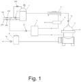
- Fig. 1 is a structural schematic diagram of the present invention.
- the slop oils that appear in the petroleum and petrochemical industries have a common feature, namely, the oil-water mixture contains a large amount of sludge and solid impurities. It also confirms the research on the related emulsification mechanism in the laboratory from one aspect.
- the solid impurities such as sludge in slop oil has many sources. At present, the main sources of pollution in the domestic petroleum and petrochemical industry are listed as follows.
- slop oil will be continuously produced in the oil refining factory, which generally appears in the oil skimming processing tank of the wastewater treatment plant, or is stored at the bottom of the crude oil storage tank.
- the slop oil of the third source is produced due to irregular accidents of electric dehydration in the refining factory.
- Fig. 1 is a structural schematic diagram of the present invention.
- the slop oil treating device includes the pretreatment device 1, the solid-liquid separator 2, the demulsification nucleus-increasing treating device 3, the squeezing filter press 4, the three-phase separator 5, the buffer tank 6, the feeding pump 71, the circulating pump 72, the conveying pump 73, and the outputting pump 74.
- Slop oil in an oil tank is delivered to the pretreatment device 1 through the feeding pump 71 for pre-treatment.
- the slop oil is subjected to a pre-heating at a temperature ranging from 90°C to 92°C in the pretreatment device 1, and conveyed to the solid-liquid separator 2 for separation.
- Solid residue obtained after a first-stage separation enters the squeezing filter press 4 for solid-liquid squeezing.
- the squeezing filter press 4 discharges the squeezed solid residue, and conveys the squeezed waste water to the demulsification nucleus-increasing treating device 3, and then the squeezed waste water is conveyed to the pretreatment device 1 through the circulating pump 72.
- Oil separated by the three-phase separator 5 is conveyed to the buffer tank 6, and conveyed to a storage tank through the outputting pump 74, water separated by the three-phase separator 5 is conveyed to a waste water treatment workshop for processing, and emulsion separated by the three-phase separator 5 is conveyed to the demulsification nucleus-increasing treating device 3 for a nucleus-increasing pretreatment, and then returned to the pretreatment device 1 and the solid-liquid separator 2.
- the regulating valve A 102 is mounted on the slop oil conveying pipe 101, and the regulating valve A 102 is configured to regulate a flow rate through the feeding pump 71.
- the regulating valve B 104 is mounted on the steam conveying pipe 103, and the regulating valve B 104 is configured to regulate a flow rate of steam conveyed to the pretreatment device 1.
- the gate valve 105 is mounted in parallel between the pretreatment device 1 and the slop oil conveying pipe 101.
- the solid residue discharge After a squeezing is performed by the squeezing filter press 4, the solid residue discharge has a water content of less than 65%, and an oil content of less than 2-3%.
- BS& W basic sediments and water
- OIW oil in water
- the solid residue is firstly dewatered under a positive pressure intensity by the squeezing filter press 4, which is also called slurry dewatering. Namely, a predetermined number of filter plates are closely arranged in a row under an action of strong mechanical force, filter chambers are formed between surfaces of the filter plates, the material to be filtered is conveyed into the filter chamber under a strong positive pressure.
- the solid portion of the material to be filtered entering the filter chamber is trapped by a filter medium to form a filter cake, and the liquid portion is discharged from the filter chamber through the filter medium, thereby achieving the purpose of the solid-liquid separation. As the positive pressure intensity increases, the solid-liquid separation becomes more thorough.
- the separation using the three-phase separator 5 belongs to the second-stage separation.
- the separation of the three-phase separator 5 is a high-speed centrifugal separation of oil and water.
- the second-stage separation brings three products: the oil having a BS&W of 0.6-1.5%, the water having an OIW of 55-150 ppm, and the emulsion having a BS&W of 5-12%.
- the contents of the three products are related to the oil products.
- a preliminary oil-water separation may also be achieved.
- the oil in water (OIW) concentration of the separated water can reach below 250 ppm, and the water content in the oil phase is between 7% and 15%.
- the composition of the solid impurities obtained in the first-stage separation is related to the characteristics of the slop oil, wherein the content of the free-state crude oil is equal to or less than 1.2% to 2.5% (by weight), the water content is 75% to 85% (by weight), and the organic matter content in the solid is between 25% and 35%.
- the water content of the solid residue can reach less than 65%.
- a mixture of the solid residue and a part of the treated oil can enter the coking production line as a raw material to avoid hazardous waste treatment.
- the water content of the oil phase from the outlet of the second-stage treatment ranges from 0.6% to 1.5%.
- the oil inorganic solid content (excluding coke powder) is less than 0.8%, and the oil in water (OIW) concentration of water phase ranges from 80 ppm to 500 ppm, which is related to the oil products as well.
- the present invention is designed in combination with the existing process conditions at the production site, corresponding changes are made according to different oil products and on-site process conditions, and the operating parameters are adjusted on the spot for different oil products as well.
- the optimum temperature of the pre-heating of the slop oil is 90-92°C
- the back pressures of the receiving ends of the oil phase and the water phase should be less than 0.2 MPa (30 PSI)
- the inlet pressure of the slop oil is 0.2-0.4 MPa (30-60 psi)
- the processing capacity of the single device can reach 8-12m 3 /h.
Landscapes
- Chemical & Material Sciences (AREA)
- Chemical Kinetics & Catalysis (AREA)
- Oil, Petroleum & Natural Gas (AREA)
- Physics & Mathematics (AREA)
- Thermal Sciences (AREA)
- Engineering & Computer Science (AREA)
- General Chemical & Material Sciences (AREA)
- Organic Chemistry (AREA)
- Production Of Liquid Hydrocarbon Mixture For Refining Petroleum (AREA)
Claims (4)
- Rückstandsölbehandlungsvorrichtung, umfassend: eine Vorbehandlungsvorrichtung (1), einen Fest-Flüssig-Trenner (2), eine Demulgierungskernvergrößerungsbehandlungsvorrichtung (3), eine Membranfilterpresse (4), einen Dreiphasentrenner (5), einen Pufferbehälter (6), eine Speisepumpe (71), eine Zirkulationspumpe (72), eine Förderpumpe (73) und eine Ausgabepumpe (74), wobeidie Speisepumpe (71) mit der Vorbehandlungsvorrichtung (1) verbunden ist und Rückstandsöl, das eine emulgierte Öl-Wasser-Mischung in einem Ölbehälter enthält, der Vorbehandlungsvorrichtung (1) durch die Speisepumpe (71) für eine Vorbehandlung zugeführt wird;die Vorbehandlungsvorrichtung (1) mit dem Fest-Flüssig-Trenner (2) verbunden ist und das Rückstandsöl in der Vorbehandlungsvorrichtung (1) bei einer Temperatur von 90 °C bis 92 °C vorgeheizt und anschließend zum Fest-Flüssig-Trenner (2) für eine Trennung der ersten Stufe geleitet wird;die Membranfilterpresse (4) jeweils mit dem Fest-Flüssig-Trenner (2) und der Demulgierungskernvergrößerungsbehandlungsvorrichtung (3) verbunden ist, die Zirkulationspumpe (72) jeweils mit der Demulgierungskernvergrößerungsbehandlungsvorrichtung (3) und der Vorbehandlungsvorrichtung (1) verbunden ist, ein fester Rückstand nach der Trennung der ersten Stufe in die Membranfilterpresse (4) für die Fest-Flüssig-Trennung per Pressen gelangt, die Membranfilterpresse (4) einen gepressten festen Rückstand ablässt und gepresstes Abwasser zur Demulgierungskernvergrößerungsbehandlungsvorrichtung (3) leitet und das gepresste Abwasser anschließend durch die Zirkulationspumpe (72) zur Vorbehandlungsvorrichtung (1) geleitet wird, undder Dreiphasentrenner (5) jeweils mit der Förderpumpe (73) der Demulgierungskernvergrößerungsbehandlungsvorrichtung (3) und dem Pufferbehälter (6) verbunden ist, die Förderpumpe (73) mit dem Fest-Flüssig-Trenner (2) verbunden ist, die Ausgabepumpe (74) mit dem Pufferbehälter (6) verbunden ist, eine Öl-und-Wasser-Mischung nach der Trennung der ersten Stufe in den Dreiphasentrenner (5) für eine Hochgeschwindigkeitszentrifugaltrennung der zweiten Stufe gelangt, ein vom Dreiphasentrenner (5) getrenntes Öl zum Pufferbehälter (6) geleitet wird und durch die Ausgabepumpe (74) zu einem Speicherbehälter geleitet wird, das vom Dreiphasentrenner (5) getrennte Wasser zur Aufbereitung zu einer Abwasserbehandlungsanlage geleitet wird und eine vom Dreiphasentrenner (5) getrennte Emulsion für eine Kernvergrößerungsbehandlung zur Demulgierungskernvergrößerungsbehandlungsvorrichtung (3) geleitet und anschließend zurück zur Vorbehandlungsvorrichtung (1) und zum Fest-Flüssig-Trenner (2) geleitet wird, dadurch gekennzeichnet, dassder Fest-Flüssig-Trenner (2) stromabwärts der Vorbehandlungsvorrichtung (1) befindlich und mit dieser verbunden ist, der Dreiphasentrenner (5) stromabwärts des Fest-Flüssig-Trenners (2) befindlich und mit diesem verbunden ist, die Demulgierungskernvergrößerungsbehandlungsvorrichtung (3) stromabwärts sowohl des Fest-Flüssig-Trenners (2) als auch des Dreiphasentrenners (5) befindlich und mit diesen verbunden ist und die Membranfilterpresse (4) zwischen dem Fest-Flüssig-Trenner (2) und der Demulgierungskernvergrößerungsbehandlungsvorrichtung (3) verbunden ist.
- Rückstandsölbehandlungsvorrichtung nach Anspruch 1, dadurch gekennzeichnet, dass ein Regelventil A (102) an einer Rückstandsölförderleitung (101) montiert ist und das Regelventil A (102) ausgelegt ist, um einen Förderstrom durch die Speisepumpe (71) zu regeln.
- Rückstandsölbehandlungsvorrichtung nach Anspruch 2, dadurch gekennzeichnet, dass ein Regelventil B (104) ist an einer Dampfförderleitung (103) montiert ist und das Regelventil B (104) ausgelegt ist, um einen Förderstrom von Dampf, der zur Vorbehandlungsvorrichtung (1) geleitet wird, zu regeln.
- Rückstandsölbehandlungsvorrichtung nach Anspruch 3, dadurch gekennzeichnet, dass Absperrventil (105) parallel zwischen der Vorbehandlungsvorrichtung (1) und der Rückstandsölförderleitung (101) montiert ist.
Applications Claiming Priority (1)
| Application Number | Priority Date | Filing Date | Title |
|---|---|---|---|
| CN201910075633.1A CN109652119B (zh) | 2019-01-26 | 2019-01-26 | 污油/老化油处理设备 |
Publications (3)
| Publication Number | Publication Date |
|---|---|
| EP3686263A1 EP3686263A1 (de) | 2020-07-29 |
| EP3686263B1 true EP3686263B1 (de) | 2025-01-01 |
| EP3686263C0 EP3686263C0 (de) | 2025-01-01 |
Family
ID=66121459
Family Applications (1)
| Application Number | Title | Priority Date | Filing Date |
|---|---|---|---|
| EP19199239.5A Active EP3686263B1 (de) | 2019-01-26 | 2019-09-24 | Altölbehandlungsvorrichtung |
Country Status (3)
| Country | Link |
|---|---|
| US (1) | US20200238198A1 (de) |
| EP (1) | EP3686263B1 (de) |
| CN (1) | CN109652119B (de) |
Families Citing this family (10)
| Publication number | Priority date | Publication date | Assignee | Title |
|---|---|---|---|---|
| CN112174400B (zh) * | 2020-10-15 | 2024-11-26 | 郑州恒博环境科技股份有限公司 | 一种废旧乳化液的处理系统 |
| CA3153460A1 (en) * | 2021-03-30 | 2022-09-30 | Kyata Capital Inc. | Systems and methods for removing contaminants from surfaces of solid material |
| CN113666593A (zh) * | 2021-09-07 | 2021-11-19 | 濮阳市科润石油工程技术有限公司 | 一种油田污泥处理系统 |
| CN114292661A (zh) * | 2021-12-17 | 2022-04-08 | 中洁环淼(江苏)环境科技有限公司 | 一种油田老化油处理方法及处理系统 |
| CN114470966B (zh) * | 2022-02-10 | 2024-02-09 | 远大(湖南)再生燃油股份有限公司 | 一种废矿物油的生产装置 |
| US20230313051A1 (en) * | 2022-04-04 | 2023-10-05 | Saudi Arabian Oil Company | Systems and methods to use steam to break emulsions in crude |
| CN114768304B (zh) * | 2022-05-17 | 2023-07-14 | 北京恒诺信达生物技术有限公司 | 一种餐厨剩余物渗滤液油脂分离方法及系统 |
| CN117819747A (zh) * | 2022-09-26 | 2024-04-05 | 淄博凯美可工贸有限公司 | 浮渣污泥处理系统及方法 |
| CN116622405A (zh) * | 2023-07-06 | 2023-08-22 | 新疆聚力环保科技有限公司 | 基于加氢原油的过滤废渣分离出油份的系统 |
| CN118047519A (zh) * | 2024-04-01 | 2024-05-17 | 天津昌海江汉石油机械装备有限公司 | 一种含油污泥三相分离一体化处理系统及工艺 |
Family Cites Families (11)
| Publication number | Priority date | Publication date | Assignee | Title |
|---|---|---|---|---|
| BR8504611A (pt) * | 1985-09-20 | 1987-04-28 | Petroleo Brasileiro Sa | Processo para separar agua e solidos de combustiveis,em particular de oleo de xisto |
| US6576145B2 (en) * | 1997-02-27 | 2003-06-10 | Continuum Environmental, Llc | Method of separating hydrocarbons from mineral substrates |
| CN2677000Y (zh) * | 2003-12-11 | 2005-02-09 | 陈国信 | 油田老化油处理成套装置 |
| CN201268599Y (zh) * | 2008-07-23 | 2009-07-08 | 大庆腾辉石油工程技术服务有限公司 | 污油处理装置 |
| CN101602566B (zh) * | 2009-07-10 | 2012-09-05 | 北京惠博普能源技术有限责任公司 | 一种针对油田含油污泥的综合处理工艺 |
| CN102039301B (zh) * | 2010-09-30 | 2013-04-10 | 昆明理工大学 | 一种含油污泥资源化-无害化综合处理工艺 |
| CN103013557A (zh) * | 2012-12-27 | 2013-04-03 | 北京惠博普能源技术有限责任公司 | 一种油田和炼油厂用老化污油处理工艺 |
| CN105417906A (zh) * | 2015-12-10 | 2016-03-23 | 李准 | 一种油田污泥处理装置 |
| SE539859C2 (en) * | 2016-05-10 | 2017-12-19 | Recondoil Sweden Ab | Method and system for purification of slop oil and industrial emulsions comprising two processes run in parallel |
| CN106608706A (zh) * | 2016-06-21 | 2017-05-03 | 陕西欧菲德环保科技有限公司 | 一种含油污泥无害化处理资源化利用方法 |
| CN107216912A (zh) * | 2017-07-30 | 2017-09-29 | 毛明艳 | 一种油田老乳化油处理方法及处理装置 |
-
2019
- 2019-01-26 CN CN201910075633.1A patent/CN109652119B/zh active Active
- 2019-05-15 US US16/412,455 patent/US20200238198A1/en not_active Abandoned
- 2019-09-24 EP EP19199239.5A patent/EP3686263B1/de active Active
Also Published As
| Publication number | Publication date |
|---|---|
| EP3686263A1 (de) | 2020-07-29 |
| US20200238198A1 (en) | 2020-07-30 |
| CN109652119B (zh) | 2020-08-11 |
| CN109652119A (zh) | 2019-04-19 |
| EP3686263C0 (de) | 2025-01-01 |
Similar Documents
| Publication | Publication Date | Title |
|---|---|---|
| EP3686263B1 (de) | Altölbehandlungsvorrichtung | |
| Sun et al. | Physical pretreatment of petroleum refinery wastewater instead of chemicals addition for collaborative removal of oil and suspended solids | |
| CN101186355B (zh) | 原油电脱盐装置含油切水的综合处理方法及装置 | |
| CN111170552B (zh) | 取消气浮的含油污水预处理方法和装置 | |
| CN1197794C (zh) | 一种含油污泥的处理方法 | |
| CN103755052B (zh) | 一种石油炼化废水电脱盐黑液的处理方法及系统 | |
| CN104944619B (zh) | 重质原油加工过程中电脱盐污水除油方法 | |
| CN112499733A (zh) | 一种基于电场协同介质聚结的o/w乳状液破乳除油装置和方法 | |
| CN103361165B (zh) | 用于轧钢过程中产生的废乳化液的再生设备和方法 | |
| CN102949866A (zh) | 一种石油化工乳化工艺水除油方法 | |
| CN108379880A (zh) | 一种含焦粉的油水混合物的分离设备及分离方法 | |
| CN102226100B (zh) | 一种高效原油脱盐/脱水方法及设备 | |
| CN113277597A (zh) | 含油废水异质结微通道分离方法及装置 | |
| CN109135819B (zh) | 一种处理油井原油的系统和方法 | |
| CN1016355B (zh) | 用过滤法对石油脱盐脱水 | |
| CN105950212A (zh) | 一种老化污油处理工艺 | |
| CN104944496A (zh) | 涉及煤焦油加工的硫酸钠废水除酚方法 | |
| CN202152289U (zh) | 一种乳化油污水气浮处理装置 | |
| RU2146549C1 (ru) | Установка обезвоживания и обессоливания нефти | |
| CN107099325A (zh) | 一种污油脱盐脱水的方法 | |
| CN214400183U (zh) | 一种提取油泥中油分的系统 | |
| CN212655678U (zh) | 一种含油污泥超声波破乳分离装置 | |
| RU2739189C1 (ru) | Способ переработки нефтешлама | |
| CN108439627A (zh) | 一种对含油乳状液污水破乳的工艺系统及方法 | |
| CN101492217A (zh) | 用于含白油污水处理的装置及方法 |
Legal Events
| Date | Code | Title | Description |
|---|---|---|---|
| PUAI | Public reference made under article 153(3) epc to a published international application that has entered the european phase |
Free format text: ORIGINAL CODE: 0009012 |
|
| STAA | Information on the status of an ep patent application or granted ep patent |
Free format text: STATUS: REQUEST FOR EXAMINATION WAS MADE |
|
| 17P | Request for examination filed |
Effective date: 20190924 |
|
| AK | Designated contracting states |
Kind code of ref document: A1 Designated state(s): AL AT BE BG CH CY CZ DE DK EE ES FI FR GB GR HR HU IE IS IT LI LT LU LV MC MK MT NL NO PL PT RO RS SE SI SK SM TR |
|
| AX | Request for extension of the european patent |
Extension state: BA ME |
|
| GRAP | Despatch of communication of intention to grant a patent |
Free format text: ORIGINAL CODE: EPIDOSNIGR1 |
|
| STAA | Information on the status of an ep patent application or granted ep patent |
Free format text: STATUS: GRANT OF PATENT IS INTENDED |
|
| RIC1 | Information provided on ipc code assigned before grant |
Ipc: B01D 17/12 20060101ALI20240919BHEP Ipc: B01D 17/02 20060101ALI20240919BHEP Ipc: B01D 17/00 20060101ALI20240919BHEP Ipc: C10G 53/02 20060101ALI20240919BHEP Ipc: C10G 33/00 20060101ALI20240919BHEP Ipc: C10G 31/10 20060101ALI20240919BHEP Ipc: C10G 31/09 20060101ALI20240919BHEP Ipc: C10G 31/08 20060101AFI20240919BHEP |
|
| INTG | Intention to grant announced |
Effective date: 20241014 |
|
| GRAS | Grant fee paid |
Free format text: ORIGINAL CODE: EPIDOSNIGR3 |
|
| GRAA | (expected) grant |
Free format text: ORIGINAL CODE: 0009210 |
|
| STAA | Information on the status of an ep patent application or granted ep patent |
Free format text: STATUS: THE PATENT HAS BEEN GRANTED |
|
| RAP3 | Party data changed (applicant data changed or rights of an application transferred) |
Owner name: XINCHANG TECHNOLOGY CO., LTD. |
|
| AK | Designated contracting states |
Kind code of ref document: B1 Designated state(s): AL AT BE BG CH CY CZ DE DK EE ES FI FR GB GR HR HU IE IS IT LI LT LU LV MC MK MT NL NO PL PT RO RS SE SI SK SM TR |
|
| REG | Reference to a national code |
Ref country code: GB Ref legal event code: FG4D |
|
| REG | Reference to a national code |
Ref country code: DE Ref legal event code: R096 Ref document number: 602019064172 Country of ref document: DE |
|
| REG | Reference to a national code |
Ref country code: CH Ref legal event code: EP |
|
| REG | Reference to a national code |
Ref country code: IE Ref legal event code: FG4D |
|
| U01 | Request for unitary effect filed |
Effective date: 20250101 |
|
| U07 | Unitary effect registered |
Designated state(s): AT BE BG DE DK EE FI FR IT LT LU LV MT NL PT RO SE SI Effective date: 20250114 |
|
| PG25 | Lapsed in a contracting state [announced via postgrant information from national office to epo] |
Ref country code: PL Free format text: LAPSE BECAUSE OF FAILURE TO SUBMIT A TRANSLATION OF THE DESCRIPTION OR TO PAY THE FEE WITHIN THE PRESCRIBED TIME-LIMIT Effective date: 20250101 |
|
| PG25 | Lapsed in a contracting state [announced via postgrant information from national office to epo] |
Ref country code: ES Free format text: LAPSE BECAUSE OF FAILURE TO SUBMIT A TRANSLATION OF THE DESCRIPTION OR TO PAY THE FEE WITHIN THE PRESCRIBED TIME-LIMIT Effective date: 20250101 |
|
| PG25 | Lapsed in a contracting state [announced via postgrant information from national office to epo] |
Ref country code: NO Free format text: LAPSE BECAUSE OF FAILURE TO SUBMIT A TRANSLATION OF THE DESCRIPTION OR TO PAY THE FEE WITHIN THE PRESCRIBED TIME-LIMIT Effective date: 20250401 Ref country code: IS Free format text: LAPSE BECAUSE OF FAILURE TO SUBMIT A TRANSLATION OF THE DESCRIPTION OR TO PAY THE FEE WITHIN THE PRESCRIBED TIME-LIMIT Effective date: 20250501 |
|
| PG25 | Lapsed in a contracting state [announced via postgrant information from national office to epo] |
Ref country code: HR Free format text: LAPSE BECAUSE OF FAILURE TO SUBMIT A TRANSLATION OF THE DESCRIPTION OR TO PAY THE FEE WITHIN THE PRESCRIBED TIME-LIMIT Effective date: 20250101 |
|
| PG25 | Lapsed in a contracting state [announced via postgrant information from national office to epo] |
Ref country code: GR Free format text: LAPSE BECAUSE OF FAILURE TO SUBMIT A TRANSLATION OF THE DESCRIPTION OR TO PAY THE FEE WITHIN THE PRESCRIBED TIME-LIMIT Effective date: 20250402 |
|
| PG25 | Lapsed in a contracting state [announced via postgrant information from national office to epo] |
Ref country code: CZ Free format text: LAPSE BECAUSE OF FAILURE TO SUBMIT A TRANSLATION OF THE DESCRIPTION OR TO PAY THE FEE WITHIN THE PRESCRIBED TIME-LIMIT Effective date: 20250101 |
|
| U20 | Renewal fee for the european patent with unitary effect paid |
Year of fee payment: 7 Effective date: 20250729 |
|
| PG25 | Lapsed in a contracting state [announced via postgrant information from national office to epo] |
Ref country code: SM Free format text: LAPSE BECAUSE OF FAILURE TO SUBMIT A TRANSLATION OF THE DESCRIPTION OR TO PAY THE FEE WITHIN THE PRESCRIBED TIME-LIMIT Effective date: 20250101 |
|
| PG25 | Lapsed in a contracting state [announced via postgrant information from national office to epo] |
Ref country code: SK Free format text: LAPSE BECAUSE OF FAILURE TO SUBMIT A TRANSLATION OF THE DESCRIPTION OR TO PAY THE FEE WITHIN THE PRESCRIBED TIME-LIMIT Effective date: 20250101 |
|
| PLBE | No opposition filed within time limit |
Free format text: ORIGINAL CODE: 0009261 |
|
| STAA | Information on the status of an ep patent application or granted ep patent |
Free format text: STATUS: NO OPPOSITION FILED WITHIN TIME LIMIT |
|
| 26N | No opposition filed |
Effective date: 20251002 |