EP3686074A1 - Multi-circuit safety valve for a compressed air system - Google Patents
Multi-circuit safety valve for a compressed air system Download PDFInfo
- Publication number
- EP3686074A1 EP3686074A1 EP20152577.1A EP20152577A EP3686074A1 EP 3686074 A1 EP3686074 A1 EP 3686074A1 EP 20152577 A EP20152577 A EP 20152577A EP 3686074 A1 EP3686074 A1 EP 3686074A1
- Authority
- EP
- European Patent Office
- Prior art keywords
- valve
- circuit protection
- diaphragm
- compressed air
- protection valve
- Prior art date
- Legal status (The legal status is an assumption and is not a legal conclusion. Google has not performed a legal analysis and makes no representation as to the accuracy of the status listed.)
- Granted
Links
- 239000012528 membrane Substances 0.000 claims description 26
- 230000008929 regeneration Effects 0.000 description 16
- 238000011069 regeneration method Methods 0.000 description 16
- 238000009423 ventilation Methods 0.000 description 14
- 244000037459 secondary consumers Species 0.000 description 13
- 230000005540 biological transmission Effects 0.000 description 3
- 239000000725 suspension Substances 0.000 description 3
- 239000011324 bead Substances 0.000 description 2
- 238000010276 construction Methods 0.000 description 2
- 230000007547 defect Effects 0.000 description 2
- 230000001419 dependent effect Effects 0.000 description 2
- 238000012423 maintenance Methods 0.000 description 2
- 238000000034 method Methods 0.000 description 2
- 230000003584 silencer Effects 0.000 description 2
- 238000011144 upstream manufacturing Methods 0.000 description 2
- 238000013022 venting Methods 0.000 description 2
- 230000002950 deficient Effects 0.000 description 1
- 238000013461 design Methods 0.000 description 1
- 238000001514 detection method Methods 0.000 description 1
- 238000011161 development Methods 0.000 description 1
- 230000018109 developmental process Effects 0.000 description 1
- 238000007599 discharging Methods 0.000 description 1
- 238000001035 drying Methods 0.000 description 1
- 230000007257 malfunction Effects 0.000 description 1
- 238000004519 manufacturing process Methods 0.000 description 1
- 230000036316 preload Effects 0.000 description 1
- 238000005096 rolling process Methods 0.000 description 1
- 230000001953 sensory effect Effects 0.000 description 1
- 230000036962 time dependent Effects 0.000 description 1
Images


Classifications
-
- B—PERFORMING OPERATIONS; TRANSPORTING
- B60—VEHICLES IN GENERAL
- B60T—VEHICLE BRAKE CONTROL SYSTEMS OR PARTS THEREOF; BRAKE CONTROL SYSTEMS OR PARTS THEREOF, IN GENERAL; ARRANGEMENT OF BRAKING ELEMENTS ON VEHICLES IN GENERAL; PORTABLE DEVICES FOR PREVENTING UNWANTED MOVEMENT OF VEHICLES; VEHICLE MODIFICATIONS TO FACILITATE COOLING OF BRAKES
- B60T17/00—Component parts, details, or accessories of power brake systems not covered by groups B60T8/00, B60T13/00 or B60T15/00, or presenting other characteristic features
- B60T17/04—Arrangements of piping, valves in the piping, e.g. cut-off valves, couplings or air hoses
-
- B—PERFORMING OPERATIONS; TRANSPORTING
- B60—VEHICLES IN GENERAL
- B60T—VEHICLE BRAKE CONTROL SYSTEMS OR PARTS THEREOF; BRAKE CONTROL SYSTEMS OR PARTS THEREOF, IN GENERAL; ARRANGEMENT OF BRAKING ELEMENTS ON VEHICLES IN GENERAL; PORTABLE DEVICES FOR PREVENTING UNWANTED MOVEMENT OF VEHICLES; VEHICLE MODIFICATIONS TO FACILITATE COOLING OF BRAKES
- B60T11/00—Transmitting braking action from initiating means to ultimate brake actuator without power assistance or drive or where such assistance or drive is irrelevant
- B60T11/10—Transmitting braking action from initiating means to ultimate brake actuator without power assistance or drive or where such assistance or drive is irrelevant transmitting by fluid means, e.g. hydraulic
- B60T11/28—Valves specially adapted therefor
- B60T11/32—Automatic cut-off valves for defective pipes
- B60T11/326—Automatic cut-off valves for defective pipes in pneumatic systems
-
- B—PERFORMING OPERATIONS; TRANSPORTING
- B60—VEHICLES IN GENERAL
- B60T—VEHICLE BRAKE CONTROL SYSTEMS OR PARTS THEREOF; BRAKE CONTROL SYSTEMS OR PARTS THEREOF, IN GENERAL; ARRANGEMENT OF BRAKING ELEMENTS ON VEHICLES IN GENERAL; PORTABLE DEVICES FOR PREVENTING UNWANTED MOVEMENT OF VEHICLES; VEHICLE MODIFICATIONS TO FACILITATE COOLING OF BRAKES
- B60T17/00—Component parts, details, or accessories of power brake systems not covered by groups B60T8/00, B60T13/00 or B60T15/00, or presenting other characteristic features
- B60T17/04—Arrangements of piping, valves in the piping, e.g. cut-off valves, couplings or air hoses
- B60T17/043—Brake line couplings, air hoses and stopcocks
-
- B—PERFORMING OPERATIONS; TRANSPORTING
- B60—VEHICLES IN GENERAL
- B60T—VEHICLE BRAKE CONTROL SYSTEMS OR PARTS THEREOF; BRAKE CONTROL SYSTEMS OR PARTS THEREOF, IN GENERAL; ARRANGEMENT OF BRAKING ELEMENTS ON VEHICLES IN GENERAL; PORTABLE DEVICES FOR PREVENTING UNWANTED MOVEMENT OF VEHICLES; VEHICLE MODIFICATIONS TO FACILITATE COOLING OF BRAKES
- B60T17/00—Component parts, details, or accessories of power brake systems not covered by groups B60T8/00, B60T13/00 or B60T15/00, or presenting other characteristic features
- B60T17/18—Safety devices; Monitoring
Definitions
- the invention relates to a multi-circuit protection valve of a compressed air system of a motor vehicle, which is arranged between the output connection of a compressed air supply system and the input connections of a plurality of consumer circuits, and in which a circuit protection valve is arranged for at least some consumer circuits, each of which is in a connecting line between the output connection of the compressed air supply system and the input connection of the relevant consumer group are arranged.
- a multi-circuit protection valve has the function of independently forwarding the compressed air present at an outlet connection of a compressed air supply system to the consumer circuits and, in the event of a failure or defect in one of the consumer circuits, automatically disconnecting it from the compressed air supply, so that the other consumer groups continue to operate can be supplied with compressed air.
- the input connections of the consumer circuits are each connected to the output connection of the compressed air supply system or a pressure-carrying supply line of another consumer circuit via a circuit protection valve arranged within the multi-circuit protection valve.
- the circuit protection valves are usually designed as passively controlled, that is to say automatically active, overflow valves, in which the ratio between opening and closing pressure is geometrically determined, and in which one of these two pressures is to be defined by a spring force.
- An overflow valve opens when the pressure at the inlet connection has reached or exceeded the set opening pressure. It closes when the closing pressure of the overflow valve on the active surface of the piston or the diaphragm in the valve is reached or fallen below due to a pressure drop at the outlet connection.
- the overflow valves of the secondary consumer circuits including the overflow valve of the parking brake circuit, usually have a higher opening pressure than the overflow valves of the service brake circuits.
- the overflow valves of the secondary consumer circuits can also be connected serially downstream of the service brake circuits to the compressed air supply within the multi-circuit protection valve.
- a multi-circuit protection valve of a compressed air brake system in which a pressure relief valve is connected upstream of the two overflow valves of three secondary consumer circuits and the overflow valves of the relevant secondary consumer circuits are connected in series with the overflow valves of the two service brake circuits.
- a multi-circuit protection valve with four overflow valves arranged in series and designed as diaphragm valves with a common supply chamber and a common diaphragm is shown in FIG DE 10 2012 014 733 A1 known.
- the function of the circuit protection valves is determined by the mechanically predetermined opening and closing pressures and is limited to this function. For example, if a circuit protection valve is designed as an overflow valve, it is not possible to open a circuit protection valve before reaching or exceeding the opening pressure or after reaching or falling below the closing pressure. Likewise, the closing of a circuit protection valve as required after reaching or exceeding the opening pressure or before reaching or falling below the closing pressure is not possible when the circuit protection valve is designed as an overflow valve.
- overflow valves there is a design requirement to provide different multi-circuit protection valves for motor vehicles of different weight classes and to adjust them to the respective motor vehicle, the specifications of the respective vehicle manufacturer and international legal regulations by adjusting the preload of the spring elements on the overflow valves. Due to operational wear on the switching elements (membranes or pistons) and the valve seats of the overflow valves as well as fatigue of the spring elements a mechanical readjustment of the overflow valves is also required at certain operating time-dependent and / or route-dependent intervals.
- a multi-circuit protection valve with several overflow valves is described, of which an electromagnet is integrated in one of the overflow valves.
- the overflow valve in question is arranged in series with the overflow valves of the two service brake circuits and is assigned to the parking brake circuit and the trailer supply circuit.
- the relevant overflow valve can be opened if necessary below the closing pressure, so that a subsequent supply of the connected consumer circuits is possible without a compressed air tank connected there.
- the additional function of this known overflow valve is, however, limited to electromagnetic opening.
- the present invention was based on the object of presenting a multi-circuit protection valve of a compressed air system of a motor vehicle of the type mentioned at the outset, which can be used universally for motor vehicles of different weight classes, and whose circuit protection valves with a simple structure are easily adapted to the respective motor vehicle and to the specifications of the respective vehicle manufacturer and in Special functions can be opened and closed regardless of the intended opening and closing pressures.
- the invention accordingly relates to a multi-circuit protection valve of a compressed air system of a motor vehicle, which is arranged between the output connection of a compressed air supply system and the input connections of a plurality of consumer circuits, and in which a circuit protection valve is arranged for at least some consumer circuits, each of which is located in a connecting line between the output connection of the Compressed air supply system and the input connection of the relevant consumer group are arranged.
- this multi-circuit protection valve also provides that at least one of the circuit protection valves is designed as a shut-off valve that can be actively controlled by an electronic control unit via an electrical control line, and that at least on the outlet-side sections of the connecting lines of the service brake circuits and the parking brake circuit Pressure sensor is connected, which is integrated in the electronic control unit or connected to the electronic control unit via an electrical sensor line.
- At least one circuit protection valve as a shut-off valve that can be actively controlled by an electronic control unit
- the at least one consumer circuit connected to it can be supplied with compressed air flexibly or be separated from the compressed air supply.
- the opening pressure and the closing pressure of the actively controllable shut-off valve are no longer technically specified, but are now stored as control parameters in a data memory of the electronic control unit and can therefore be flexibly adapted to different vehicle classes, specifications of the vehicle manufacturers and different international regulations. Since the pressures present in the service brake circuits and the parking brake circuit are detected by the pressure sensors provided, the relevant safety regulations, which, for example, provide first-class ventilation of the service brake circuits, can be complied with without any problems.
- the circuit protection valve of the parking brake circuit is designed as an actively controllable shut-off valve. If a defect now occurs on one or both service brake circuits and the motor vehicle in question must therefore be towed, the parking brake circuit can now be ventilated in a special function without external ventilation via its own compressed air supply system and the parking brakes can thus be released.
- the circuit protection valves of the service brake circuits and the parking brake circuit are designed as actively controllable shut-off valves.
- the brake circuits form the most important consumer circuits, so that it is advantageous if they are connected to or disconnected from the compressed air supply via actively controllable shut-off valves.
- a mechanical readjustment required for overflow valves due to wear on certain components is not required for actively controllable shut-off valves, so that the function of the service brakes and the parking brakes is guaranteed without maintenance work over a longer operating time in consistent quality.
- An actively controllable shut-off valve could be designed as a directly controlled solenoid valve, but this would be associated with a relatively large electromagnet and a correspondingly high power consumption.
- an actively controllable shut-off valve could also be designed as a pressure-controlled switching valve, the control input of which is alternately acted upon by a high control pressure or depressurized via a 3/2-way solenoid valve or two 2/2-way solenoid valves.
- Such an embodiment of an actively controllable shut-off valve would, however, be associated with a high apparatus structure, a correspondingly large space requirement and with an increased susceptibility to malfunction.
- At least one of the actively controllable shut-off valves is designed as a pneumatically servo-assisted 2/2-way solenoid switching valve, the switching element of which is loaded or resilient in the opening sense by means of a spring element and the pneumatic pressure applied to an output connection and by an electromagnet as well as the pneumatic pressure applied to an input connection is resilient in the closing sense.
- the pneumatic servo support reduces the current consumption of the electromagnet when the valve is closed and the valve is kept open with low current consumption.
- the shut-off valve is designed as a diaphragm seat valve, the diaphragm of which cooperates with a valve seat arranged on the inner edge of a central sleeve fixed to the housing and, together with an inner wall fixed to the housing, delimits a servo pressure chamber.
- the inlet connection of the diaphragm seat valve is connected to a cylindrical annular space which is arranged concentrically around the central sleeve.
- the outlet connection of the diaphragm seat valve is connected to a cylindrical central space which is arranged within the central sleeve.
- An electromagnet with a magnetic coil and an axially movable armature is arranged on the side of the membrane facing away from the valve seat, perpendicular to the latter.
- the armature is extended in the direction of the membrane and provided at the end with a thrust washer covering the valve seat, which is held in the de-energized state of the electromagnet by a spring element on the inner wall fixed to the housing and, when the electromagnet is energized, presses the membrane against the restoring force of the spring element against the valve seat.
- the pressure plate is only attached to the anchor-side upper side of the membrane and has a through-flow opening which is formed coaxially with a central outlet opening in the membrane, which can result in a more cost-effective production of the multi-circuit protection valve .
- the spring element of the diaphragm seat valve is designed in a space-saving manner as a helical spring which is arranged coaxially above the armature of the electromagnet and is supported axially on the inside on a ring collar fixed to the housing and axially on the outside on a ring collar of the armature.
- the membrane of the diaphragm seat valve advantageously has at least one inlet opening into the servo pressure chamber adjacent to the annular space and a centrally arranged outlet opening from the servo pressure chamber adjacent to the central space. Compressed air can enter the servo pressure chamber from the annular space through the at least one inlet opening, but occurs when the electromagnet is de-energized and thus on the inner wall fixed to the housing adjacent thrust washer through the outlet opening back into the central room.
- the pressure plate closes the outlet opening, and the compressed air entering from the annular space is then effective on the back of the pressure plate, which pneumatically supports the electromagnet .
- the diaphragm is placed on the valve seat, only a small current consumption of the electromagnet is required, because the diaphragm is then largely held pneumatically on the valve seat via the pressure plate.
- the diaphragm of the diaphragm seat valve is preferably shaped such that it contacts the inner wall of the housing when the connections are depressurized and when the electromagnet is deenergized.
- the inner wall fixed to the housing is advantageously provided with a circular disc-shaped recess which is dimensioned such that the pressure disc is largely flush with it when the electromagnet is not energized.
- FIG. 7 A compressed air supply system 2, a multi-circuit protection valve 4 and an electronic control unit 6 of a compressed air system of a motor vehicle, in particular a commercial vehicle, are shown in schematic form.
- the multi-circuit protection valve 4 is generally known and is used here, for example, as a starting example for three embodiments of a multi-circuit protection valve according to the invention, which are described below.
- a delivery line 8 runs from an input connection a1 to an output connection a2.
- the delivery output of a compressor (not shown) is connected to the input connection a1.
- a dryer unit 10 with an integrated filter unit is arranged between the inlet section 8.1 and the outlet section 8.2 of the delivery line 8.
- the dryer unit 10 is preferably provided with an exchangeable dryer and filter cartridge.
- a check valve 12 which blocks in the backflow direction is also arranged in the outlet section 8.2 of the delivery line 8.
- An external ventilation line 20 with an input connection a1.2 for external ventilation of the compressed air supply system 2 is connected to the input section 14.1 of the ventilation line 14.
- a further ventilation line 22 is connected to the input section 8.1 of the delivery line 8, which leads via a pressure relief valve 24 to a further ventilation outlet a3.1.
- the vent valve 16 is designed as a 2/2-way switching valve, which is closed when the control input is depressurized.
- the control input of the vent valve 16 is connected to a regeneration line 26 which runs from an input connection a4 to the output section 8.2 of the delivery line 8 and there between the dryer unit 10 and the check valve 12 is connected.
- a throttle check valve 28 which blocks in the backflow direction, is arranged in the regeneration line 26.
- the throttle check valve 28 is realized here as a serial arrangement of a throttle 28.1 and a check valve 28.2.
- a regeneration control valve 30 and a compressor control valve 34 are arranged within the structural unit of the multi-circuit protection valve 4.
- the regeneration control valve 30 is designed as a 2/2-way solenoid switching valve, by means of which a connecting line 32 leading to the input connection a4 of the regeneration line 26 alternately for venting the regeneration line 26 with a venting outlet or for generating a regeneration air flow with that to the output connection a2 of the delivery line 8 of the compressed air supply system 2 connected input line 38 of the multi-circuit protection valve 2 can be connected.
- the regeneration control valve 30 can be controlled by the electronic control device 6, as is illustrated by a control line drawn with a dash-dot.
- the connection line 32 and the regeneration line 26 are vented.
- the connecting line 32 and the regeneration line 26 are ventilated from the inlet line 38 and thus the drying unit 10 flows through and is regenerated with compressed air which has already dried against the conveying direction, the compressed air being passed through the vent line 14 and the then opened vent valve 16 in the environment flows out.
- the compressor control valve 34 is also designed as a 2/2-way solenoid switching valve, by means of which a control pressure line 36 leading to the control input a27 of the compressor can alternately be connected to a ventilation outlet or to the input line 38 of the multi-circuit protection valve 2.
- the compressor control valve 34 can also be controlled by the electronic control unit 6, as is illustrated by a further control line drawn with a dash-dot. In the de-energized state of the Compressor control valve 34, the control pressure line 36 is vented, so that the control input a27 of the compressor is depressurized, whereby the compressor is switched on or remains switched on.
- the control pressure line 36 is vented from the inlet line 38 with compressed air, so that the control input a27 of the compressor is pressurized, whereby the compressor is switched off.
- the compressor is usually switched off both during a regeneration operation, that is to say when the regeneration control valve 30 is switched over, and also when the compressed air tanks of the compressed air system are completely filled.
- three connecting lines 40, 44, 48, each provided with an overflow valve 42, 46, 50, are connected in parallel between the input line 38 and the input connections a21.1, a21.2; a22.1, a22.2; a25.1, a25.2 of two first service brake circuits a21.1, a21.2, two second service brake circuits a22.1, a22.2 and two air suspension circuits a25.1, a25.2.
- Three further connecting lines 56, 60, 64 each provided with an overflow valve 58, 62, 66 are connected in parallel between a connecting line 52 provided with a pressure relief valve 54 and connected to the input line 38 and the input connections a23.1, a23.2; a24.1, a24.2; a26.1, a26.2 of two parking brake circuits a23.1, a23.2, two transmission control circuits a24.1, 24.2 and two secondary consumer circuits a26.1, a26.2 connected.
- the priority ventilation of the service brake circuits a21.1, a21.2; a22.1, a22.2 and the subordinate ventilation of the parking brake circuits a23.1, a23.2 is achieved by lower opening pressures at the overflow valves 42, 46 and a higher opening pressure at the overflow valve 58.
- the parking brake circuits a23.1, a23.2, the transmission control circuits a24.1, 24.2 and the secondary consumer circuits a26.1, a26.2 are upstream of the higher pressure level for the service brake circuits a21.1, a21.2; a22.1, a22.2 and the air suspension circuits a15.1, a25.2 are protected.
- a pressure sensor 68, 72, 76, 80 and a temperature sensor 70, 74, 78, 82 are connected, which in the present case are integrated in the electronic control unit 6.
- These sensors are used to record the air pressure and the air temperature in the relevant consumer groups a21.1, a21.2; a22.1, a22.2; a23.1, a23.2; a26.1, a26.2.
- a shut-off valve 84 actively controllable by the electronic control unit 6 via an electrical control line 86.
- the shut-off valve 84 is designed as a pneumatically servo-assisted 2/2-way magnetic switching valve, the switching element of which is loaded or can be loaded in the opening sense by a spring element and the pneumatic pressure applied to an output connection and by an electromagnet and the pneumatic pressure applied to an input connection conclusive sense is resilient.
- the standard functions such as the priority ventilation of the service brake circuits a21.1, a21.2; a22.1, a22.2 and the subordinate ventilation of the parking brake circuits a23.1, a23.2 is also ensured with the actively controllable shut-off valve 84, since the relevant air pressures are recorded via the pressure sensors 68, 72, 76 in question.
- the parking brake circuits a23.1, a23.2 can now be vented in a special function even without external ventilation via the company's own compressed air supply system 2 and the parking brakes can thus be released if the motor vehicle in question is defective in one of the service brake circuits a21.1, a21. 2; a22.1, a22.2 must be towed.
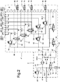
- a multi-circuit protection valve 4 according to the invention Fig. 2 in addition to the overflow valve 58 for the parking brake circuits a23.1, a23.2, the overflow valves 42, 46 for the service brake circuits a21.1, a21.2; a22.1, a22.2 are replaced by shut-off valves 84, 88, 92 which can be actively controlled by the electronic control device 6 via an electrical control line 86, 90, 94 in each case.
- the standard functions are guaranteed on the basis of the sensory detection of the relevant air pressures.
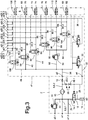
- a third embodiment of a multi-circuit protection valve 4 * according to the invention Fig. 3 are now in contrast to the known multi-circuit protection valve 4 according to Fig. 7 the overflow valves 42, 46, 50, 58, 62, 66 for all consumer circuits a21.1, a21.2; a22.1, a22.2; a23.1, a23.2; a24.1, a24.2; a25.1, a25.2; a26.1, a26.2 are replaced by shut-off valves 84, 88, 92, 96, 100, 104 that can be actively controlled by the electronic control unit 6 via an electrical control line 86, 90, 94, 98, 102, 106.
- a pressure sensor 108, 112 and a temperature sensor 110, 114 are now also connected to the output sections 48.2, 60.2 of the connecting lines 48, 60 for the air suspension circuits a25.1, a25.2 and the transmission control circuits a24.1, 24.2.
- all consumer circuits a21.1, a21.2; a22.1, a22.2; a23.1, a23.2; a24.1, a24.2; a25.1, a25.2; a26.1, a26.2 can be connected to or disconnected from the compressed air supply in a fully variable manner.
- the shut-off valve 84 is designed as a diaphragm seat valve 120 with an inlet connection 122 and an outlet connection 124 and has a base housing 126, an upper housing part 128 and a housing cover 130.
- a cylindrical central sleeve 132 is arranged in the interior of the base housing 126 Figures 4 to 6 upper edge has a valve seat 134.
- the input connection 122 is connected via an input channel 136 to a cylindrical annular space 138 which is arranged concentrically around the central sleeve 132.
- Of the Output connection 124 is connected via an output channel 140 to a cylindrical central space 142, which is formed within the central sleeve 132.
- a largely circular disk-shaped membrane 144 is arranged above the valve seat 134, engages with an outer annular bead 146 in an annular groove 148 of the base housing 126, and is clamped between the base housing 126 and the housing upper part 128. Together with an inner wall 150 of the upper housing part 128, the membrane 144 delimits a servo pressure space 152.
- An electromagnet 154 with a magnet coil 156 and an axially movable armature 158 is arranged on the side of the diaphragm 144 facing away from the valve seat 134 perpendicular to the latter.
- the magnetic coil 156 is arranged in a recess in the upper housing part 128 and fixed by the housing cover 130.
- the armature 158 is elongated in the direction of the membrane 144 and, in this exemplary embodiment, is provided at the end with a thrust washer 160 covering the valve seat 134.
- this thrust washer 160 can also be fastened only on the armature-side upper side of the membrane 144 with respect to the then free end of the armature 158.
- the pressure disc 160 is held in the deenergized state of the electromagnet 154 by a spring element 162 on the housing-fixed inner wall 150 and, when the electromagnet 154 is energized, presses the membrane 144 against the restoring force of the spring element 162 against the valve seat 134.
- the spring element 162 is designed in a space-saving manner as a helical spring which coaxially surrounds the armature 158 of the electromagnet 154 and is supported axially on the inside on a ring collar 164 fixed to the housing and axially on the outside on a ring collar 166 of the armature 158.
- the membrane 144 has at least one inlet opening 168 into the servo pressure chamber 152 adjacent to the annular space 138 and, adjacent to the central space 142, a centrally arranged outlet opening 170 for discharging air from the servo pressure chamber 152.
- the inner wall 150 fixed to the housing has a circular-disk-shaped recess 172 which is dimensioned such that the pressure disk 160 of the armature 158 is received therein largely flush when the electromagnet 154 is de-energized.
- Fig. 4 the diaphragm valve 120 is shown in its idle state, in which the connections 122, 124 are depressurized and the electromagnet 154 is de-energized.
- the thrust washer 160 of the armature 158 lies largely flush against the inner wall 150 fixed to the housing within the recess 172, and the membrane 144, which is of constant thickness, rests on the inner wall 150 and the thrust washer 160 of the armature 158 due to a corresponding shape. Since the membrane 144 is lifted off the valve seat 134, the input connection 122 and the output connection 124 are connected to one another, so that the membrane valve 120 is opened.
- Fig. 5 the diaphragm valve 120 is shown in a first operating state, in which the input connection 122 is pressurized, but the electromagnet 154 is still de-energized.
- compressed air now flows from the inlet connection 122 via the annular space 138, the valve seat 134 and the central space 142 to the outlet connection 124.
- Compressed air can also flow into the servo pressure space 152 via the at least one inlet opening 168 of the membrane 144 and for lifting the membrane 144 care of the housing-fixed inner wall 150 and the thrust washer 160.
- the membrane 144 is only slightly pressed off from the inner wall 150 fixed to the housing, so that the membrane valve 120 remains open.
- Fig. 6 the diaphragm valve 120 is shown in a second operating state, in which the input connection 122 is still pressure-carrying, but the electromagnet 154 is now energized.
- the armature 158 of the electromagnet 154 has entered the servo pressure chamber 152 and has pressed the diaphragm 144 with the thrust washer 160 against the valve seat 134, so that the diaphragm valve 120 is now closed.
- Diaphragm valve 120 can be closed and kept closed with a relatively low current consumption of the electromagnet 154.
- the diaphragm valve 120 presented is particularly well suited for use as an actively controllable circuit protection valve 84 in a multi-circuit protection valve 4 ', 4 ", 4 *.
Abstract
Die Erfindung betrifft ein Mehrkreisschutzventil (4') einer Druckluftanlage eines Kraftfahrzeugs, das zwischen dem Ausgangsanschluss (a2) einer Druckluftversorgungsanlage (2) und den Eingangsanschlüssen (a21.1, a21.2; a22.1, a22.2; a23.1, a23.2; a24.1, a24.2; a25.1, a25.2; a26.1, a26.2) mehrerer Verbraucherkreise angeordnet ist, und in dem für zumindest einige Verbraucherkreise jeweils ein Kreisschutzventil angeordnet ist, welche jeweils in einer Verbindungsleitung zwischen dem Ausgangsanschluss (a2) der Druckluftversorgungsanlage (2) und dem Eingangsanschluss des betreffenden Verbraucherkreises angeordnet sind. Zur Erhöhung des Einsatzbereiches des Mehrkreisschutzventils (4') und der leichteren Anpassung seiner Kreisschutzventile (42, 46, 50, 62, 66, 84) an das jeweilige Kraftfahrzeug sowie an die Vorgaben des jeweiligen Fahrzeugherstellers und der Ermöglichung von Sonderfunktionen außerhalb der vorgesehenen Öffnungs- und Schließdrücke ist vorgesehen, dass mindestens eines der Kreisschutzventile (84) als ein von einem elektronischen Steuergerät (ECU, 6) über jeweils eine elektrische Steuerleitung (86) aktiv steuerbares Absperrventil ausgebildet ist, und dass zumindest an den ausgangsseitigen Abschnitten (40.2, 44.2, 56.2) der Verbindungsleitungen (40, 44, 56) der Betriebsbremskreise und des Feststellbremskreises jeweils ein Drucksensor (68, 72, 76) angeschlossen ist, der in das elektronische Steuergerät (6) integriert oder über eine elektrische Sensorleitung an das elektronische Steuergerät (6) angeschlossen ist.The invention relates to a multi-circuit protection valve (4 ') of a compressed air system of a motor vehicle, which is located between the output connection (a2) of a compressed air supply system (2) and the input connections (a21.1, a21.2; a22.1, a22.2; a23.1, a23.2; a24.1, a24.2; a25.1, a25.2; a26.1, a26.2) of several consumer circuits, and in which a circuit protection valve is arranged for at least some consumer circuits, each in a Connection line between the output connection (a2) of the compressed air supply system (2) and the input connection of the relevant consumer circuit are arranged. To increase the area of application of the multi-circuit protection valve (4 ') and to adapt its circuit protection valves (42, 46, 50, 62, 66, 84) more easily to the respective motor vehicle as well as to the specifications of the respective vehicle manufacturer and to enable special functions outside the intended opening It is provided that at least one of the circuit protection valves (84) is designed as a shut-off valve that can be actively controlled by an electronic control unit (ECU, 6) via an electrical control line (86), and that at least on the outlet-side sections (40.2, 44.2, 56.2) of the connecting lines (40, 44, 56) of the service brake circuits and the parking brake circuit, a pressure sensor (68, 72, 76) is connected, which is integrated in the electronic control unit (6) or via an electrical sensor line to the electronic control unit (6) connected.
Description
Die Erfindung betrifft ein Mehrkreisschutzventil einer Druckluftanlage eines Kraftfahrzeugs, das zwischen dem Ausgangsanschluss einer Druckluftversorgungsanlage und den Eingangsanschlüssen mehrerer Verbraucherkreise angeordnet ist, und in dem für zumindest einige Verbraucherkreise jeweils ein Kreisschutzventil angeordnet ist, welche jeweils in einer Verbindungsleitung zwischen dem Ausgangsanschluss der Druckluftversorgungsanlage und dem Eingangsanschluss des betreffenden Verbraucherkreises angeordnet sind.The invention relates to a multi-circuit protection valve of a compressed air system of a motor vehicle, which is arranged between the output connection of a compressed air supply system and the input connections of a plurality of consumer circuits, and in which a circuit protection valve is arranged for at least some consumer circuits, each of which is in a connecting line between the output connection of the compressed air supply system and the input connection of the relevant consumer group are arranged.
In einer mehrere Verbraucherkreise aufweisenden Druckluftanlage hat ein Mehrkreisschutzventil die Funktion, die an einem Ausgangsanschluss einer Druckluftversorgungsanlage anstehende Druckluft unabhängig voneinander an die Verbraucherkreise weiterzuleiten, und bei einem Ausfall oder Defekt eines der Verbraucherkreise diesen automatisch von der Druckluftversorgung zu trennen, so dass die übrigen Verbraucherkreise weiterhin mit Druckluft versorgt werden können. Hierzu stehen die Eingangsanschlüsse der Verbraucherkreise über jeweils ein innerhalb des Mehrkreisschutzventils angeordnetes Kreisschutzventil mit dem Ausgangsanschluss der Druckluftversorgungsanlage oder einer druckführenden Versorgungsleitung eines anderen Verbraucherkreises in Verbindung.In a compressed air system having several consumer circuits, a multi-circuit protection valve has the function of independently forwarding the compressed air present at an outlet connection of a compressed air supply system to the consumer circuits and, in the event of a failure or defect in one of the consumer circuits, automatically disconnecting it from the compressed air supply, so that the other consumer groups continue to operate can be supplied with compressed air. For this purpose, the input connections of the consumer circuits are each connected to the output connection of the compressed air supply system or a pressure-carrying supply line of another consumer circuit via a circuit protection valve arranged within the multi-circuit protection valve.
Die Kreisschutzventile sind üblicherweise als passiv gesteuerte, also selbsttätig wirksame Überströmventile ausgebildet, bei denen das Verhältnis zwischen Öffnungs- und Schließdruck geometrisch bestimmt ist, und bei denen einer dieser beiden Drücke durch eine Federkraft zu definieren ist. Ein Überströmventil öffnet zunächst dann, wenn der am Eingangsanschluss anliegende Druck den eingestellten Öffnungsdruck erreicht oder überschritten hat. Es schließt dann, wenn durch einen Druckabfall am Ausgangsanschluss der Schließdruck des Überströmventils an der Wirkfläche des Kolbens oder der Membran im Ventil erreicht oder unterschritten wird.The circuit protection valves are usually designed as passively controlled, that is to say automatically active, overflow valves, in which the ratio between opening and closing pressure is geometrically determined, and in which one of these two pressures is to be defined by a spring force. An overflow valve opens when the pressure at the inlet connection has reached or exceeded the set opening pressure. It closes when the closing pressure of the overflow valve on the active surface of the piston or the diaphragm in the valve is reached or fallen below due to a pressure drop at the outlet connection.
Damit die Betriebsbremskreise bei der Inbetriebnahme des betreffenden Fahrzeugs zuerst mit Druckluft aufgefüllt und einschlägige EU-Richtlinien bezüglich des Lösens der Feststellbremsen erfüllt werden, weisen die Überströmventile der Sekundärverbraucherkreise einschließlich des Überströmventils des Feststellbremskreises üblicherweise einen höheren Öffnungsdruck als die Überströmventile der Betriebsbremskreise auf. Alternativ zu einer parallelen Anordnung der Überströmventile können die Überströmventile der Sekundärverbraucherkreise hierzu innerhalb des Mehrkreisschutzventils den Betriebsbremskreisen auch seriell nachgeschaltet an die Druckluftversorgung angeschlossen sein.To ensure that the service brake circuits are first filled with compressed air when the relevant vehicle is started up and relevant EU directives regarding the release of the parking brakes are met, the overflow valves of the secondary consumer circuits, including the overflow valve of the parking brake circuit, usually have a higher opening pressure than the overflow valves of the service brake circuits. As an alternative to a parallel arrangement of the overflow valves, the overflow valves of the secondary consumer circuits can also be connected serially downstream of the service brake circuits to the compressed air supply within the multi-circuit protection valve.
Durch den seriellen Anschluss der Überströmventile der Sekundärverbraucherkreise an die Ausgangsabschnitte der Verbindungsleitungen der Betriebsbremskreise und/oder den höheren Öffnungsdruck der Überströmventile der Sekundärverbraucherkreise werden diese erst dann belüftet, wenn die Überströmventile der Betriebsbremskreise bereits geöffnet sind, und sich in den Ausgangsabschnitten der Verbindungsleitungen der Betriebsbremskreise ein den Öffnungsdruck der Überströmventile der Sekundärverbraucherkreise übersteigender Druck eingestellt hat. Dadurch ist sichergestellt, dass die mit Federspeicherbremsen versehene Feststellbremsanlage erst dann mit Druckluft versorgt wird und damit ein Lösen der Feststellbremsen möglich ist, wenn die Betriebsbremskreise hinreichend mit Druckluft aufgefüllt sind, so dass das betreffende Kraftfahrzeug nach dem Lösen der Feststellbremsen mittels der Betriebsbremsen abgebremst oder zumindest an einem Wegrollen gehindert werden kann. Die Verbraucher der übrigen Sekundärverbraucherkreise werden dadurch ebenfalls nachrangig mit Druckluft versorgt.Due to the serial connection of the overflow valves of the secondary consumer circuits to the output sections of the connecting lines of the service brake circuits and / or the higher opening pressure of the overflow valves of the secondary consumer circuits, these are only ventilated when the overflow valves of the service brake circuits are already open and become in the output sections of the connecting lines of the service brake circuits has set the pressure exceeding the opening pressure of the overflow valves of the secondary consumer circuits. This ensures that the parking brake system provided with spring-loaded brakes is only supplied with compressed air and that the parking brakes can only be released when the service brake circuits are sufficiently filled with compressed air so that the motor vehicle in question is braked or at least braked by the service brakes after the parking brakes have been released can be prevented from rolling away. The consumers of the other secondary consumer groups are also subordinated to compressed air.
Aus der
In der WABCO-Druckschrift "Grundlehrgang 7, Vierkreis-Schutzventile", die im Internet als PDF-Datei unter http://inform.wabco-auto.com/intl/pdf/815/00/57/8150100573-07.pdf heruntergeladen werden kann, ist der Aufbau und die Funktionsweise eines Vierkreisschutzventils mit vier paarweise gegenüberliegend angeordneten, als Membranventile ausgeführten Überströmventilen beschrieben. In einer ersten Ausführung des Vierkreisschutzventils sind die beiden Überströmventile von zwei Sekundärverbraucherkreisen den beiden Überströmventilen der beiden Betriebsbremskreise seriell nachgeschaltet angeordnet. In einer zweiten Ausführung des Vierkreisschutzventils sind die beiden Überströmventile der zwei Sekundärverbraucherkreise parallel zu den beiden Überströmventilen der beiden Betriebsbremskreise angeordnet.In the WABCO publication "Basic course 7, four-circuit protection valves", which is downloaded from the Internet as a PDF file at http://inform.wabco-auto.com/intl/pdf/815/00/57/8150100573-07.pdf can be described, the structure and operation of a four-circuit protection valve with four oppositely arranged, designed as diaphragm valves overflow valves is described. In a first embodiment of the four-circuit protection valve, the two overflow valves of two secondary consumer circuits are arranged in series after the two overflow valves of the two service brake circuits. In a second embodiment of the four-circuit protection valve, the two overflow valves of the two secondary consumer circuits are arranged parallel to the two overflow valves of the two service brake circuits.
Ein Mehrkreisschutzventil mit vier in Reihe angeordneten, als Membranventile ausgeführten Überströmventilen mit einer gemeinsamen Versorgungskammer und einer gemeinsamen Membran ist aus der
Bei Mehrkreisschutzventilen mit selbsttätig wirksamen, als Membran- oder Kolbenventile ausgeführten Überströmventilen ist die Funktion der Kreisschutzventile durch die mechanisch vorgegebenen Öffnungs- und Schließdrücke festgelegt und auf diese Funktion beschränkt. So ist zum Beispiel das bedarfsweise Öffnen eines Kreisschutzventils vor dem Erreichen oder Überschreiten des Öffnungsdruckes oder nach dem Erreichen oder Unterschreiten des Schließdruckes bei einer Ausführung des Kreisschutzventils als Überströmventil nicht möglich. Ebenso ist das bedarfsweise Schließen eines Kreisschutzventils nach dem Erreichen oder Überschreiten des Öffnungsdruckes oder vor dem Erreichen oder Unterschreiten des Schließdruckes bei einer Ausführung des Kreisschutzventils als Überströmventil nicht möglich. Zudem besteht bei der Verwendung von Überströmventilen bauartbedingt die Notwendigkeit, für Kraftfahrzeuge verschiedener Gewichtsklassen unterschiedliche Mehrkreisschutzventile vorzusehen und diese durch die Justierung der Vorspannung der Federelemente an den Überströmventilen an das jeweilige Kraftfahrzeug, die Vorgaben des jeweiligen Fahrzeugherstellers sowie international unterschiedliche gesetzliche Regelungen anzupassen. Aufgrund von betriebsbedingtem Verschleiß an den Schaltelementen (Membranen oder Kolben) und den Ventilsitzen der Überströmventile sowie einer Ermüdung der Federelemente ist zudem in bestimmten betriebszeitabhängigen und/oder fahrstreckenabhängigen Abständen eine mechanische Nachjustierung der Überströmventile erforderlich.In the case of multi-circuit protection valves with automatically acting overflow valves designed as diaphragm or piston valves, the function of the circuit protection valves is determined by the mechanically predetermined opening and closing pressures and is limited to this function. For example, if a circuit protection valve is designed as an overflow valve, it is not possible to open a circuit protection valve before reaching or exceeding the opening pressure or after reaching or falling below the closing pressure. Likewise, the closing of a circuit protection valve as required after reaching or exceeding the opening pressure or before reaching or falling below the closing pressure is not possible when the circuit protection valve is designed as an overflow valve. In addition, when using overflow valves, there is a design requirement to provide different multi-circuit protection valves for motor vehicles of different weight classes and to adjust them to the respective motor vehicle, the specifications of the respective vehicle manufacturer and international legal regulations by adjusting the preload of the spring elements on the overflow valves. Due to operational wear on the switching elements (membranes or pistons) and the valve seats of the overflow valves as well as fatigue of the spring elements a mechanical readjustment of the overflow valves is also required at certain operating time-dependent and / or route-dependent intervals.
In der
Der vorliegenden Erfindung lag die Aufgabe zugrunde, ein Mehrkreisschutzventil einer Druckluftanlage eines Kraftfahrzeugs der eingangs genannten Bauart vorzustellen, welches universell für Kraftfahrzeuge unterschiedlicher Gewichtsklassen verwendbar ist, und dessen Kreisschutzventile bei einfachem Aufbau leicht an das jeweilige Kraftfahrzeug sowie an die Vorgaben des jeweiligen Fahrzeugherstellers angepasst und in Sonderfunktionen unabhängig von den vorgesehenen Öffnungs- und Schließdrücken sowohl geöffnet als auch geschlossen werden können.The present invention was based on the object of presenting a multi-circuit protection valve of a compressed air system of a motor vehicle of the type mentioned at the outset, which can be used universally for motor vehicles of different weight classes, and whose circuit protection valves with a simple structure are easily adapted to the respective motor vehicle and to the specifications of the respective vehicle manufacturer and in Special functions can be opened and closed regardless of the intended opening and closing pressures.
Die Lösung dieser Aufgabe wird mit einem Mehrkreisschutzventil erreicht, welches die Merkmale des Anspruchs 1 aufweist. Vorteilhafte Weiterbildungen sind in den abhängigen Ansprüchen definiert.This object is achieved with a multi-circuit protection valve, which has the features of
Die Erfindung betrifft demnach ein Mehrkreisschutzventil einer Druckluftanlage eines Kraftfahrzeugs, das zwischen dem Ausgangsanschluss einer Druckluftversorgungsanlage und den Eingangsanschlüssen mehrerer Verbraucherkreise angeordnet ist, und in dem für zumindest einige Verbraucherkreise jeweils ein Kreisschutzventil angeordnet ist, welche jeweils in einer Verbindungsleitung zwischen dem Ausgangsanschluss der Druckluftversorgungsanlage und dem Eingangsanschluss des betreffenden Verbraucherkreises angeordnet sind.The invention accordingly relates to a multi-circuit protection valve of a compressed air system of a motor vehicle, which is arranged between the output connection of a compressed air supply system and the input connections of a plurality of consumer circuits, and in which a circuit protection valve is arranged for at least some consumer circuits, each of which is located in a connecting line between the output connection of the Compressed air supply system and the input connection of the relevant consumer group are arranged.
Zur Lösung der gestellten Aufgabe ist bei diesem Mehrkreisschutzventil außerdem vorgesehen, dass mindestens eines der Kreisschutzventile als ein von einem elektronischen Steuergerät über jeweils eine elektrische Steuerleitung aktiv steuerbares Absperrventil ausgebildet ist, und dass zumindest an den ausgangsseitigen Abschnitten der Verbindungsleitungen der Betriebsbremskreise und des Feststellbremskreises jeweils ein Drucksensor angeschlossen ist, der in das elektronische Steuergerät integriert oder über eine elektrische Sensorleitung an das elektronische Steuergerät angeschlossen ist.To achieve the object, this multi-circuit protection valve also provides that at least one of the circuit protection valves is designed as a shut-off valve that can be actively controlled by an electronic control unit via an electrical control line, and that at least on the outlet-side sections of the connecting lines of the service brake circuits and the parking brake circuit Pressure sensor is connected, which is integrated in the electronic control unit or connected to the electronic control unit via an electrical sensor line.
Durch die Ausbildung mindestens eines Kreisschutzventils als ein von einem elektronischen Steuergerät aktiv steuerbares Absperrventil kann der mindestens eine an dieses angeschlossene Verbraucherkreis flexibel mit Druckluft versorgt oder von der Druckluftversorgung getrennt werden. Der Öffnungsdruck und der Schließdruck des aktiv steuerbaren Absperrventils sind nicht mehr technisch vorgegeben, sondern sind nun als Steuerparameter in einem Datenspeicher der elektronischen Steuereinheit abgespeichert und können somit flexibel an unterschiedliche Fahrzeugklassen, Vorgaben der Fahrzeughersteller und international unterschiedliche gesetzliche Regelungen angepasst werden. Da die in den Betriebsbremskreisen und dem Feststellbremskreis anliegenden Drücke über die vorgesehenen Drucksensoren erfasst werden, können die einschlägigen Sicherheitsvorschriften, die zum Beispiel die erstrangige Belüftung der Betriebsbremskreise vorsehen, problemlos eingehalten werden.By designing at least one circuit protection valve as a shut-off valve that can be actively controlled by an electronic control unit, the at least one consumer circuit connected to it can be supplied with compressed air flexibly or be separated from the compressed air supply. The opening pressure and the closing pressure of the actively controllable shut-off valve are no longer technically specified, but are now stored as control parameters in a data memory of the electronic control unit and can therefore be flexibly adapted to different vehicle classes, specifications of the vehicle manufacturers and different international regulations. Since the pressures present in the service brake circuits and the parking brake circuit are detected by the pressure sensors provided, the relevant safety regulations, which, for example, provide first-class ventilation of the service brake circuits, can be complied with without any problems.
Gemäß einer ersten Ausgestaltung des erfindungsgemäßen Mehrkreisschutzventils ist vorgesehen, dass zumindest das Kreisschutzventil des Feststellbremskreises als ein aktiv steuerbares Absperrventil ausgebildet ist. Wenn nun ein Defekt an einem oder beiden Betriebsbremskreisen auftritt und das betreffende Kraftfahrzeug deshalb abgeschleppt werden muss, kann der Feststellbremskreis in einer Sonderfunktion nun ohne eine Fremdbelüftung über die eigene Druckluftversorgungsanlage belüftet und somit die Feststellbremsen gelöst werden.According to a first embodiment of the multi-circuit protection valve according to the invention, it is provided that at least the circuit protection valve of the parking brake circuit is designed as an actively controllable shut-off valve. If a defect now occurs on one or both service brake circuits and the motor vehicle in question must therefore be towed, the parking brake circuit can now be ventilated in a special function without external ventilation via its own compressed air supply system and the parking brakes can thus be released.
Gemäß einer zweiten Ausgestaltung des erfindungsgemäßen Mehrkreisschutzventils ist vorgesehen, dass zumindest die Kreisschutzventile der Betriebsbremskreise und des Feststellbremskreises als aktiv steuerbare Absperrventile ausgebildet sind. Die Bremskreise bilden die wichtigsten Verbraucherkreise, so dass es vorteilhaft ist, wenn diese über aktiv steuerbare Absperrventile mit der Druckluftversorgung verbunden oder von dieser getrennt werden. Eine bei Überströmventilen aufgrund von Verschleiß an bestimmten Bauteilen erforderliche mechanische Nachjustierung entfällt bei aktiv steuerbaren Absperrventilen, so dass die Funktion der Betriebsbremsen und der Feststellbremsen ohne Wartungsarbeiten über eine längere Betriebszeit in gleichbleibender Qualität gewährleistet ist.According to a second embodiment of the multi-circuit protection valve according to the invention, it is provided that at least the circuit protection valves of the service brake circuits and the parking brake circuit are designed as actively controllable shut-off valves. The brake circuits form the most important consumer circuits, so that it is advantageous if they are connected to or disconnected from the compressed air supply via actively controllable shut-off valves. A mechanical readjustment required for overflow valves due to wear on certain components is not required for actively controllable shut-off valves, so that the function of the service brakes and the parking brakes is guaranteed without maintenance work over a longer operating time in consistent quality.
Ein aktiv steuerbares Absperrventil könnte als ein direkt angesteuertes Magnetventil ausgebildet sein, was jedoch mit einem relativ großen Elektromagneten und einem entsprechend hohen Stromverbrauch verbunden wäre. Alternativ dazu könnte ein aktiv steuerbares Absperrventil auch als ein druckgesteuertes Schaltventil ausgebildet sein, dessen Steuereingang über ein 3/2-Wege-Magnetschaltventil oder zwei 2/2-Wege-Magnetschaltventile wechselweise mit einem hohen Steuerdruck beaufschlagt oder drucklos geschaltet wird. Eine derartige Ausbildung eines aktiv steuerbaren Absperrventils wäre jedoch mit einem hohen apparativen Aufbau, einem entsprechend großen Bauraumbedarf und mit einer erhöhten Störungsanfälligkeit verbunden.An actively controllable shut-off valve could be designed as a directly controlled solenoid valve, but this would be associated with a relatively large electromagnet and a correspondingly high power consumption. Alternatively, an actively controllable shut-off valve could also be designed as a pressure-controlled switching valve, the control input of which is alternately acted upon by a high control pressure or depressurized via a 3/2-way solenoid valve or two 2/2-way solenoid valves. Such an embodiment of an actively controllable shut-off valve would, however, be associated with a high apparatus structure, a correspondingly large space requirement and with an increased susceptibility to malfunction.
Daher ist erfindungsgemäß vorgesehen, dass mindestens eines der aktiv steuerbaren Absperrventile als ein pneumatisch servounterstütztes 2/2-Wege-Magnetschaltventil ausgebildet ist, dessen Schaltelement mittels eines Federelementes sowie den an einem Ausgangsanschluss anliegenden pneumatischen Druck im öffnenden Sinn belastet beziehungsweise belastbar ist und durch einen Elektromagneten sowie den an einem Eingangsanschluss anliegenden pneumatischen Druck im schließenden Sinn belastbar ist. Durch die pneumatische Servounterstützung wird die Stromaufnahme des Elektromagneten beim Schließen des Ventils reduziert und das Ventil mit geringer Stromaufnahme im geöffneten Zustand gehalten.It is therefore provided according to the invention that at least one of the actively controllable shut-off valves is designed as a pneumatically servo-assisted 2/2-way solenoid switching valve, the switching element of which is loaded or resilient in the opening sense by means of a spring element and the pneumatic pressure applied to an output connection and by an electromagnet as well as the pneumatic pressure applied to an input connection is resilient in the closing sense. The pneumatic servo support reduces the current consumption of the electromagnet when the valve is closed and the valve is kept open with low current consumption.
Gemäß einer bevorzugten Konstruktion ist vorgesehen, dass das Absperrventil als ein Membransitzventil ausgebildet ist, dessen Membran mit einem an dem inneren Rand einer gehäusefesten Zentralhülse angeordneten Ventilsitz zusammenwirkt und zusammen mit einer gehäusefesten Innenwand einen Servodruckraum begrenzt. Der Eingangsanschluss des Membransitzventils ist mit einem zylindrischen Ringraum verbunden, der konzentrisch um die Zentralhülse angeordnet ist. Der Ausgangsanschluss des Membransitzventils ist mit einem zylindrischen Zentralraum verbunden, der innerhalb der Zentralhülse angeordnet ist. Ein Elektromagnet mit einer Magnetspule und einem axialbeweglichen Anker ist auf der dem Ventilsitz abgewandten Seite der Membran senkrecht zu dieser angeordnet. Der Anker ist in Richtung der Membran verlängert und endseitig mit einer den Ventilsitz überdeckenden Druckscheibe versehen, die im unbestromten Zustand des Elektromagneten von einem Federelement an der gehäusefesten Innenwand gehalten wird und bei bestromtem Elektromagneten die Membran entgegen der Rückstellkraft des Federelementes gegen den Ventilsitz drückt.According to a preferred construction it is provided that the shut-off valve is designed as a diaphragm seat valve, the diaphragm of which cooperates with a valve seat arranged on the inner edge of a central sleeve fixed to the housing and, together with an inner wall fixed to the housing, delimits a servo pressure chamber. The inlet connection of the diaphragm seat valve is connected to a cylindrical annular space which is arranged concentrically around the central sleeve. The outlet connection of the diaphragm seat valve is connected to a cylindrical central space which is arranged within the central sleeve. An electromagnet with a magnetic coil and an axially movable armature is arranged on the side of the membrane facing away from the valve seat, perpendicular to the latter. The armature is extended in the direction of the membrane and provided at the end with a thrust washer covering the valve seat, which is held in the de-energized state of the electromagnet by a spring element on the inner wall fixed to the housing and, when the electromagnet is energized, presses the membrane against the restoring force of the spring element against the valve seat.
Unter Nutzung der gerade geschilderten Konstruktion kann alternativ dazu vorgesehen sein, dass die Druckscheibe nur an der ankerseitigen Oberseite der Membran befestigt ist und eine Durchströmöffnung aufweist, welche koaxial zu einer mittigen Austrittsöffnung in der Membran ausgebildet ist, wodurch sich eine kostengünstigere Herstellung des Mehrkreisschutzventils ergeben kann.Using the construction just described, it can alternatively be provided that the pressure plate is only attached to the anchor-side upper side of the membrane and has a through-flow opening which is formed coaxially with a central outlet opening in the membrane, which can result in a more cost-effective production of the multi-circuit protection valve .
Das Federelement des Membransitzventils ist in platzsparender Weise als eine Schraubenfeder ausgebildet, die koaxial über dem Anker des Elektromagneten angeordnet ist und axial innen an einem gehäusefesten Ringbund sowie axial außen an einem Ringbund des Ankers abgestützt ist.The spring element of the diaphragm seat valve is designed in a space-saving manner as a helical spring which is arranged coaxially above the armature of the electromagnet and is supported axially on the inside on a ring collar fixed to the housing and axially on the outside on a ring collar of the armature.
Zur Realisierung der pneumatischen Servounterstützung weist die Membran des Membransitzventils vorteilhaft angrenzend an den Ringraum mindestens eine Eintrittsöffnung in den Servodruckraum und angrenzend an den Zentralraum eine mittig angeordnete Austrittsöffnung aus dem Servodruckraum auf. Durch die mindestens eine Eintrittsöffnung kann Druckluft aus dem Ringraum in den Servodruckraum eintreten, tritt jedoch bei stromlosem Elektromagneten und somit an der gehäusefesten Innenwand anliegender Druckscheibe über die Austrittsöffnung wieder in den Zentralraum aus. Wenn der Elektromagnet aber bestromt wird und somit der verlängerte Anker mit der Druckscheibe axial in Richtung des Ventilsitzes verschoben wird, verschließt die Druckscheibe die Austrittsöffnung, und die aus dem Ringraum eintretende Druckluft ist dann auf die Rückseite der Druckscheibe wirksam, wodurch der Elektromagnet pneumatisch unterstützt wird. Mit dem Anlegen der Membran an dem Ventilsitz ist nur noch eine geringe Stromaufnahme des Elektromagneten erforderlich, weil die Membran dann weitgehend pneumatisch über die Druckscheibe auf dem Ventilsitz gehalten wird.To implement the pneumatic servo support, the membrane of the diaphragm seat valve advantageously has at least one inlet opening into the servo pressure chamber adjacent to the annular space and a centrally arranged outlet opening from the servo pressure chamber adjacent to the central space. Compressed air can enter the servo pressure chamber from the annular space through the at least one inlet opening, but occurs when the electromagnet is de-energized and thus on the inner wall fixed to the housing adjacent thrust washer through the outlet opening back into the central room. However, when the electromagnet is energized and the elongated armature with the pressure plate is axially displaced in the direction of the valve seat, the pressure plate closes the outlet opening, and the compressed air entering from the annular space is then effective on the back of the pressure plate, which pneumatically supports the electromagnet . When the diaphragm is placed on the valve seat, only a small current consumption of the electromagnet is required, because the diaphragm is then largely held pneumatically on the valve seat via the pressure plate.
Um bei unbestromtem Elektromagneten das unkontrollierte Ein- und Ausströmen von Druckluft in den Servodruckraum zu begrenzen, ist die Membran des Membransitzventils vorzugsweise derart geformt, dass diese bei drucklosen Anschlüssen und bei unbestromtem Elektromagneten weitgehend an der gehäusefesten Innenwand anliegt.In order to limit the uncontrolled inflow and outflow of compressed air into the servo pressure chamber when the electromagnet is deenergized, the diaphragm of the diaphragm seat valve is preferably shaped such that it contacts the inner wall of the housing when the connections are depressurized and when the electromagnet is deenergized.
Damit die Membran des Membransitzventils vollständig an der gehäusefesten Innenwand anliegen und mit konstanter Dicke ausgeführt sein kann, ist die gehäusefeste Innenwand vorteilhaft mit einer kreisscheibenförmigen Vertiefung versehen, die derart dimensioniert ist, dass die Druckscheibe bei unbestromtem Elektromagneten weitgehend bündig darin aufgenommen ist.So that the diaphragm of the diaphragm seat valve lies completely against the inner wall fixed to the housing and can be made with a constant thickness, the inner wall fixed to the housing is advantageously provided with a circular disc-shaped recess which is dimensioned such that the pressure disc is largely flush with it when the electromagnet is not energized.
Die Erfindung wird nachstehend anhand mehrerer in der beigefügten Zeichnung dargestellter Ausführungsbeispiele näher erläutert. In der Zeichnung zeigt
-
Fig. 1 eine erste Ausführungsform eines erfindungsgemäßen Mehrkreisschutzventils einer Druckluftanlage in einer schematischen Ansicht, -
Fig. 2 eine zweite Ausführungsform eines erfindungsgemäßen Mehrkreisschutzventils einer Druckluftanlage in einer schematischen Ansicht, -
Fig. 3 eine dritte Ausführungsform eines erfindungsgemäßen Mehrkreisschutzventils einer Druckluftanlage in einer schematischen Ansicht, -
Fig. 4 ein erfindungsgemäßes Kreisschutzventil im unbetätigten Ruhezustand, -
Fig. 5 das Kreisschutzventil gemäßFig. 4 in einem ersten Betriebszustand, -
Fig. 6 das Kreisschutzventil gemäßFig. 4 undFig. 5 in einem zweiten Betriebszustand, und -
Fig. 7 ein bekanntes Mehrkreisschutzventil einer Druckluftanlage in einer schematischen Ansicht.
-
Fig. 1 a first embodiment of a multi-circuit protection valve according to the invention of a compressed air system in a schematic view, -
Fig. 2 2 shows a second embodiment of a multi-circuit protection valve according to the invention of a compressed air system in a schematic view, -
Fig. 3 a third embodiment of a multi-circuit protection valve according to the invention of a compressed air system in a schematic view, -
Fig. 4 a circuit protection valve according to the invention in the unactuated idle state, -
Fig. 5 the circuit protection valve according toFig. 4 in a first operating state, -
Fig. 6 the circuit protection valve according toFig. 4 andFig. 5 in a second operating state, and -
Fig. 7 a known multi-circuit protection valve of a compressed air system in a schematic view.
In
In der bekannten Druckluftversorgungsanlage 2 gemäß
An den Eingangsabschnitt 8.1 der Förderleitung 8 ist eine Entlüftungsleitung 14 angeschlossen, in der ein druckgesteuertes Entlüftungsventil 16 angeordnet ist, wobei dieser Eingangsabschnitt 8.1 über einen Schalldämpfer 18 an einen Entlüftungsausgang a3 führt. An den Eingangsabschnitt 14.1 der Entlüftungsleitung 14 ist eine Fremdbelüftungsleitung 20 mit einem Eingangsanschluss a1.2 zur Fremdbelüftung der Druckluftversorgungsanlage 2 angeschlossen. Zudem ist an den Eingangsabschnitt 8.1 der Förderleitung 8 eine weitere Entlüftungsleitung 22 angeschlossen, die über ein Druckbegrenzungsventil 24 an einen weiteren Entlüftungsausgang a3.1 führt.A
Das Entlüftungsventil 16 ist als ein 2/2-Wege-Schaltventil ausgebildet, welches bei drucklosem Steuereingang geschlossen ist. Der Steuereingang des Entlüftungsventils 16 ist an eine Regenerationsleitung 26 angeschlossen, die von einem Eingangsanschluss a4 zu dem Ausgangsabschnitt 8.2 der Förderleitung 8 verläuft und dort zwischen der Trocknereinheit 10 und dem Rückschlagventil 12 angeschlossen ist. Zwischen dem Anschluss des Steuereingangs des Entlüftungsventils 16 und dem Ausgangsabschnitt 8.2 der Förderleitung 8 ist ein in Rückströmrichtung sperrendes Drosselrückschlagventil 28 in der Regenerationsleitung 26 angeordnet. Das Drosselrückschlagventil 28 ist vorliegend als eine serielle Anordnung einer Drossel 28.1 und eines Rückschlagventils 28.2 realisiert.The
Innerhalb der Baueinheit des Mehrkreisschutzventils 4 sind ein Regenerationssteuerventil 30 und ein Kompressorsteuerventil 34 angeordnet. Das Regenerationssteuerventil 30 ist als ein 2/2-Wege-Magnetschaltventil ausgebildet, mittels dem eine an den Eingangsanschluss a4 der Regenerationsleitung 26 führende Anschlussleitung 32 wechselweise zur Entlüftung der Regenerationsleitung 26 mit einem Entlüftungsausgang oder zur Erzeugung eines Regenerationsluftstroms mit der an den Ausgangsanschluss a2 der Förderleitung 8 der Druckluftversorgungsanlage 2 angeschlossenen Eingangsleitung 38 des Mehrkreisschutzventils 2 verbindbar ist.A
Das Regenerationssteuerventil 30 ist von dem elektronischen Steuergerät 6 ansteuerbar, wie eine mit Strich-Punkt gezeichnete Steuerleitung verdeutlicht. Im unbestromten Zustand des Regenerationssteuerventils 30 werden die Anschlussleitung 32 und die Regenerationsleitung 26 entlüftet. Im bestromten Zustand des Regenerationssteuerventils 30 werden die Anschlussleitung 32 und die Regenerationsleitung 26 aus der Eingangsleitung 38 belüftet und dadurch die Trocknereinheit 10 entgegen der Förderrichtung mit bereits getrockneter Druckluft durchströmt und dadurch regeneriert, wobei die Druckluft durch die Entlüftungsleitung 14 und das dann geöffnete Entlüftungsventil 16 in die Umgebung abströmt.The
Auch das Kompressorsteuerventil 34 ist als ein 2/2-Wege-Magnetschaltventil ausgebildet, durch das eine an den Steuereingang a27 des Kompressors führende Steuerdruckleitung 36 wechselweise mit einem Entlüftungsausgang oder mit der Eingangsleitung 38 des Mehrkreisschutzventils 2 verbindbar ist. Das Kompressorsteuerventil 34 ist ebenfalls von dem elektronischen Steuergerät 6 ansteuerbar, wie es eine weitere mit Strich-Punkt gezeichnete Steuerleitung verdeutlicht. Im unbestromten Zustand des Kompressorsteuerventils 34 wird die Steuerdruckleitung 36 entlüftet, so dass der Steuereingang a27 des Kompressors drucklos ist, wodurch der Kompressor eingeschaltet ist beziehungsweise eingeschaltet bleibt. Im bestromten Zustand des Kompressorsteuerventils 34 wird die Steuerdruckleitung 36 aus der Eingangsleitung 38 mit Druckluft belüftet, sodass der Steuereingang a27 des Kompressors druckführend ist, wodurch der Kompressor abgeschaltet wird. Der Kompressor wird üblicherweise sowohl während eines Regenerationsbetriebs, also bei umgeschaltetem Regenerationssteuerventil 30, als auch bei vollständig aufgefüllten Druckluftbehältern der Druckluftanlage abgeschaltet.The
In dem Mehrkreisschutzventil 2 sind drei jeweils mit einem Überströmventil 42, 46, 50 versehene Verbindungsleitungen 40, 44, 48 parallel zwischen der Eingangsleitung 38 und den Eingangsanschlüssen a21.1, a21.2; a22.1, a22.2; a25.1, a25.2 von zwei ersten Betriebsbremskreisen a21.1, a21.2, zwei zweiten Betriebsbremskreisen a22.1, a22.2 und zwei Luftfederungskreisen a25.1, a25.2 angeordnet. Drei weitere jeweils mit einem Überströmventil 58, 62, 66 versehene Verbindungsleitungen 56, 60, 64 sind parallel zwischen einer mit einem Druckbegrenzungsventil 54 versehenen, an die Eingangsleitung 38 angeschlossenen Verbindungsleitung 52 und den Eingangsanschlüssen a23.1, a23.2; a24.1, a24.2; a26.1, a26.2 von zwei Feststellbremskreisen a23.1, a23.2, zwei Getriebesteuerungskreisen a24.1, 24.2 und zwei Nebenverbraucherkreisen a26.1, a26.2 angeschlossen. Die vorrangige Belüftung der Betriebsbremskreise a21.1, a21.2; a22.1, a22.2 und die nachrangige Belüftung der Feststellbremskreise a23.1, a23.2 wird durch niedrigere Öffnungsdrücke an den Überströmventilen 42, 46 und einen höheren Öffnungsdruck an dem Überströmventil 58 erreicht. Durch das Druckbegrenzungsventil 54 werden die Feststellbremskreise a23.1, a23.2, die Getriebesteuerungskreise a24.1, 24.2 und die Nebenverbraucherkreise a26.1, a26.2 vor dem höheren Druckniveau für die Betriebsbremskreise a21.1, a21.2; a22.1, a22.2 und die Luftfederungskreise a15.1, a25.2 geschützt.In the
An die Ausgangsabschnitte 40.2, 44.2 der Verbindungsleitungen 40, 44 für die Betriebsbremskreise a21.1, a21.2; a22.1, a22.2, an den Ausgangsabschnitt 56.2 der Verbindungsleitung 56 für die Feststellbremskreise a23.1, a23.2 sowie an den Ausgangsabschnitt 64.2 für die Nebenverbraucherkreise a26.1, a26.2 sind jeweils ein Drucksensor 68, 72, 76, 80 und ein Temperatursensor 70, 74, 78, 82 angeschlossen, die vorliegend in das elektronische Steuergerät 6 integriert sind. Diese Sensoren dienen zur Erfassung des Luftdruckes und der Lufttemperatur in den betreffenden Verbraucherkreisen a21.1, a21.2; a22.1, a22.2; a23.1, a23.2; a26.1, a26.2.At the output sections 40.2, 44.2 of the connecting
In einer in
Die Standardfunktionen, wie die vorrangige Belüftung der Betriebsbremskreise a21.1, a21.2; a22.1, a22.2 und die nachrangige Belüftung der Feststellbremskreise a23.1, a23.2, ist auch mit dem aktiv steuerbaren Absperrventil 84 gewährleistet, da die relevanten Luftdrücke über die betreffenden Drucksensoren 68, 72, 76 erfasst werden. Zusätzlich können nun aber die Feststellbremskreise a23.1, a23.2 in einer Sonderfunktion auch ohne eine Fremdbelüftung über die eigene Druckluftversorgungsanlage 2 belüftet und somit die Feststellbremsen gelöst werden, wenn das betreffende Kraftfahrzeug bei einem Defekt an einem der Betriebsbremskreise a21.1, a21.2; a22.1, a22.2 abgeschleppt werden muss.The standard functions, such as the priority ventilation of the service brake circuits a21.1, a21.2; a22.1, a22.2 and the subordinate ventilation of the parking brake circuits a23.1, a23.2 is also ensured with the actively controllable shut-off
In einer zweiten Ausführungsform eines erfindungsgemäßen Mehrkreisschutzventils 4" gemäß
Auch bei dieser Ausführungsform des Mehrkreisschutzventils 4" sind die Standardfunktionen aufgrund der sensorischen Erfassung der relevanten Luftdrücke gewährleistet. Zusätzlich entfällt aber eine bei Überströmventilen aufgrund von Verschleiß an bestimmten Bauteilen erforderliche mechanische Nachjustierung, so dass die Funktion der Betriebsbremsen und der Feststellbremsen ohne Wartungsarbeiten über eine längere Betriebszeit in gleichbleibender Qualität gewährleistet ist.In this embodiment of the
In einer dritten Ausführungsform eines erfindungsgemäßen Mehrkreisschutzventils 4* gemäß
Nachfolgend wird anhand der
Das Absperrventil 84 ist als ein Membransitzventil 120 mit einem Eingangsanschluss 122 sowie einem Ausgangsanschluss 124 ausgebildet und weist ein Basisgehäuse 126, ein Gehäuseoberteil 128 sowie einen Gehäusedeckel 130 auf. Im Inneren des Basisgehäuses 126 ist eine zylindrische Zentralhülse 132 angeordnet, die an ihrem inneren, in den
Ein Elektromagnet 154 mit einer Magnetspule 156 und einem axialbeweglichen Anker 158 ist auf der von dem Ventilsitz 134 abgewandten Seite der Membran 144 senkrecht zu dieser angeordnet. Die Magnetspule 156 ist in einer Ausnehmung des Gehäuseoberteils 128 angeordnet und durch den Gehäusedeckel 130 fixiert. Der Anker 158 ist in Richtung zu der Membran 144 verlängert ausgebildet und bei diesem Ausführungsbeispiel endseitig mit einer den Ventilsitz 134 überdeckenden Druckscheibe 160 versehen. Diese Druckscheibe 160 kann alternativ dazu auch gegenüber dem dann freien Ende des Ankers 158 nur an der ankerseitigen Oberseite der Membran 144 befestigt sein. Bei dem in den Figuren dargestellten Ausführungsbeispiel wird die Druckscheibe 160 im unbestromten Zustand des Elektromagneten 154 von einem Federelement 162 an der gehäusefesten Innenwand 150 gehalten und drückt bei bestromtem Elektromagneten 154 die Membran 144 entgegen der Rückstellkraft des Federelementes 162 gegen den Ventilsitz 134. Das Federelement 162 ist in platzsparender Weise als eine Schraubenfeder ausgebildet, die koaxial den Anker 158 des Elektromagneten 154 umgibt und axial innen an einem gehäusefesten Ringbund 164 sowie axial außen an einem Ringbund 166 des Ankers 158 abgestützt ist.An
Die Membran 144 weist angrenzend an den Ringraum 138 mindestens eine Eintrittsöffnung 168 in den Servodruckraum 152 sowie angrenzend an den Zentralraum 142 eine mittig angeordnete Austrittsöffnung 170 zur Ableitung von Luft aus dem Servodruckraum 152 auf. Die gehäusefeste Innenwand 150 weist eine kreisscheibenförmige Vertiefung 172 auf, die derart dimensioniert ist, dass die Druckscheibe 160 des Ankers 158 bei unbestromtem Elektromagneten 154 weitgehend bündig darin aufgenommen ist.The
In
In
In
Aufgrund seiner kompakten Abmessungen und seiner geringen Stromaufnahme ist das vorgestellte Membranventil 120 besonders gut für eine Verwendung als aktiv steuerbares Kreisschutzventil 84 in einem Mehrkreisschutzventil 4', 4", 4* geeignet.Due to its compact dimensions and its low current consumption, the
- 22nd
- DruckluftversorgungsanlageCompressed air supply system
- 44th
- Mehrkreisschutzventil (bekannt)Multi-circuit protection valve (known)
- 4'4 '
- Mehrkreisschutzventil (erste erfindungsgemäße Ausführungsform)Multi-circuit protection valve (first embodiment according to the invention)
- 4"4 "
- Mehrkreisschutzventil (zweite erfindungsgemäße Ausführungsform)Multi-circuit protection valve (second embodiment according to the invention)
- 4*4 *
- Mehrkreisschutzventil (dritte erfindungsgemäße Ausführungsform)Multi-circuit protection valve (third embodiment according to the invention)
- 66
- Elektronisches SteuergerätElectronic control unit
- 88th
- FörderleitungConveyor line
- 8.18.1
- EingangsabschnittEntrance section
- 8.28.2
- AusgangsabschnittExit section
- 1010th
- TrocknereinheitDryer unit
- 1212th
- Rückschlagventilcheck valve
- 1414
- EntlüftungsleitungVent line
- 14.114.1
- EingangsabschnittEntrance section
- 1616
- EntlüftungsventilVent valve
- 1818th
- Schalldämpfersilencer
- 2020
- FremdbelüftungsleitungForced ventilation line
- 2222
- EntlüftungsleitungVent line
- 2424th
- DruckbegrenzungsventilPressure relief valve
- 2626
- RegenerationsleitungRegeneration line
- 2828
- DrosselrückschlagventilThrottle check valve
- 28.128.1
- Drosselthrottle
- 28.228.2
- Rückschlagventilcheck valve
- 3030th
- RegenerationssteuerventilRegeneration control valve
- 3232
- AnschlussleitungConnecting cable
- 3434
- KompressorsteuerventilCompressor control valve
- 3636
- SteuerdruckleitungControl pressure line
- 3838
- EingangsleitungInput line
- 4040
- VerbindungsleitungConnecting line
- 40.240.2
- AusgangsabschnittExit section
- 4242
- Kreisschutzventil, ÜberströmventilCircuit protection valve, overflow valve
- 4444
- VerbindungsleitungConnecting line
- 44.244.2
- AusgangsabschnittExit section
- 4646
- Kreisschutzventil, ÜberströmventilCircuit protection valve, overflow valve
- 4848
- VerbindungsleitungConnecting line
- 48.248.2
- AusgangsabschnittExit section
- 5050
- Kreisschutzventil, ÜberströmventilCircuit protection valve, overflow valve
- 5252
- VerbindungsleitungConnecting line
- 5454
- DruckbegrenzungsventilPressure relief valve
- 5656
- VerbindungsleitungConnecting line
- 56.256.2
- AusgangsabschnittExit section
- 5858
- Kreisschutzventil, ÜberströmventilCircuit protection valve, overflow valve
- 6060
- VerbindungsleitungConnecting line
- 60.260.2
- AusgangsabschnittExit section
- 6262
- Kreisschutzventil, ÜberströmventilCircuit protection valve, overflow valve
- 6464
- VerbindungsleitungConnecting line
- 64.264.2
- AusgangsabschnittExit section
- 6666
- Kreisschutzventil, ÜberströmventilCircuit protection valve, overflow valve
- 6868
- DrucksensorPressure sensor
- 7070
- TemperatursensorTemperature sensor
- 7272
- DrucksensorPressure sensor
- 7474
- TemperatursensorTemperature sensor
- 7676
- DrucksensorPressure sensor
- 7878
- TemperatursensorTemperature sensor
- 8080
- DrucksensorPressure sensor
- 8282
- TemperatursensorTemperature sensor
- 8484
- Kreisschutzventil, AbsperrventilCircuit protection valve, shut-off valve
- 8686
- SteuerleitungControl line
- 8888
- Kreisschutzventil, AbsperrventilCircuit protection valve, shut-off valve
- 9090
- SteuerleitungControl line
- 9292
- Kreisschutzventil, AbsperrventilCircuit protection valve, shut-off valve
- 9494
- SteuerleitungControl line
- 9696
- Kreisschutzventil, AbsperrventilCircuit protection valve, shut-off valve
- 9898
- SteuerleitungControl line
- 100100
- Kreisschutzventil, AbsperrventilCircuit protection valve, shut-off valve
- 102102
- SteuerleitungControl line
- 104104
- Kreisschutzventil, AbsperrventilCircuit protection valve, shut-off valve
- 106106
- SteuerleitungControl line
- 108108
- DrucksensorPressure sensor
- 110110
- TemperatursensorTemperature sensor
- 112112
- DrucksensorPressure sensor
- 114114
- TemperatursensorTemperature sensor
- 120120
- MembranventilDiaphragm valve
- 122122
- EingangsanschlussInput connector
- 124124
- AusgangsanschlussOutput connector
- 126126
- BasisgehäuseBasic housing
- 128128
- GehäuseoberteilUpper part of the housing
- 130130
- GehäusedeckelHousing cover
- 132132
- ZentralhülseCentral sleeve
- 134134
- VentilsitzValve seat
- 136136
- EingangskanalInput channel
- 138138
- RingraumAnnulus
- 140140
- AusgangskanalOutput channel
- 142142
- ZentralraumCentral room
- 144144
- Schaltelement, MembranSwitching element, membrane
- 146146
- RingwulstRing bead
- 148148
- RingnutRing groove
- 150150
- InnenwandInterior wall
- 152152
- ServodruckraumServo printing room
- 154154
- ElektromagnetElectromagnet
- 156156
- MagnetspuleSolenoid
- 158158
- Ankeranchor
- 160160
- DruckscheibeThrust washer
- 161161
- Durchströmöffnung in der DruckscheibeFlow opening in the pressure disc
- 162162
- Federelement, SchraubenfederSpring element, coil spring
- 164164
- RingbundRing collar
- 166166
- RingbundRing collar
- 168168
- EintrittsöffnungEntrance opening
- 170170
- AustrittsöffnungOutlet opening
- 172172
- Vertiefungdeepening
- a1a1
- EingangsanschlussInput connector
- a1.2a1.2
- EingangsanschlussInput connector
- a2a2
- AusgangsanschlussOutput connector
- a3a3
- EntlüftungsausgangVent outlet
- a3.1a3.1
- EntlüftungsausgangVent outlet
- a4a4
- EingangsanschlussInput connector
- a21.1a21.1
- EingangsanschlussInput connector
- a21.2a21.2
- EingangsanschlussInput connector
- a22.1a22.1
- EingangsanschlussInput connector
- a22.2a22.2
- EingangsanschlussInput connector
- a23.1a23.1
- EingangsanschlussInput connector
- a23.2a23.2
- EingangsanschlussInput connector
- a24.1a24.1
- EingangsanschlussInput connector
- a24.2a24.2
- EingangsanschlussInput connector
- a25.1a25.1
- EingangsanschlussInput connector
- a25.2a25.2
- EingangsanschlussInput connector
- a26.1a26.1
- EingangsanschlussInput connector
- a26.2a26.2
- EingangsanschlussInput connector
- a27a27
- SteuereingangControl input
Claims (10)
Applications Claiming Priority (1)
| Application Number | Priority Date | Filing Date | Title |
|---|---|---|---|
| DE102019101685.1A DE102019101685A1 (en) | 2019-01-24 | 2019-01-24 | Multi-circuit protection valve of a compressed air system |
Publications (2)
| Publication Number | Publication Date |
|---|---|
| EP3686074A1 true EP3686074A1 (en) | 2020-07-29 |
| EP3686074B1 EP3686074B1 (en) | 2022-09-21 |
Family
ID=69185349
Family Applications (1)
| Application Number | Title | Priority Date | Filing Date |
|---|---|---|---|
| EP20152577.1A Active EP3686074B1 (en) | 2019-01-24 | 2020-01-20 | Multi-circuit safety valve for a compressed air system |
Country Status (2)
| Country | Link |
|---|---|
| EP (1) | EP3686074B1 (en) |
| DE (1) | DE102019101685A1 (en) |
Citations (5)
| Publication number | Priority date | Publication date | Assignee | Title |
|---|---|---|---|---|
| EP0810136A1 (en) * | 1996-06-01 | 1997-12-03 | WABCO GmbH | Pressure installation |
| DE102005018888B4 (en) | 2005-04-22 | 2008-07-10 | Knorr-Bremse Systeme für Nutzfahrzeuge GmbH | Valve arrangement for the supply of a commercial vehicle with compressed air |
| DE102012014733A1 (en) | 2012-07-25 | 2014-01-30 | Wabco Gmbh | Multi-circuit protection valve for an air treatment plant |
| DE102013000206A1 (en) * | 2013-01-08 | 2014-07-10 | Wabco Gmbh | Device for detecting compressed air, air treatment unit, motor vehicle therewith and method for detecting compressed air and producing a device for indicating compressed air |
| DE102017000694A1 (en) | 2017-01-17 | 2018-07-19 | Wabco Gmbh | Multi-circuit protection valve of a compressed-air brake system |
Family Cites Families (1)
| Publication number | Priority date | Publication date | Assignee | Title |
|---|---|---|---|---|
| DE19544621C1 (en) * | 1995-11-30 | 1997-01-30 | Grau Gmbh | Compressed air treatment device for automotive compressed air systems |
-
2019
- 2019-01-24 DE DE102019101685.1A patent/DE102019101685A1/en active Pending
-
2020
- 2020-01-20 EP EP20152577.1A patent/EP3686074B1/en active Active
Patent Citations (5)
| Publication number | Priority date | Publication date | Assignee | Title |
|---|---|---|---|---|
| EP0810136A1 (en) * | 1996-06-01 | 1997-12-03 | WABCO GmbH | Pressure installation |
| DE102005018888B4 (en) | 2005-04-22 | 2008-07-10 | Knorr-Bremse Systeme für Nutzfahrzeuge GmbH | Valve arrangement for the supply of a commercial vehicle with compressed air |
| DE102012014733A1 (en) | 2012-07-25 | 2014-01-30 | Wabco Gmbh | Multi-circuit protection valve for an air treatment plant |
| DE102013000206A1 (en) * | 2013-01-08 | 2014-07-10 | Wabco Gmbh | Device for detecting compressed air, air treatment unit, motor vehicle therewith and method for detecting compressed air and producing a device for indicating compressed air |
| DE102017000694A1 (en) | 2017-01-17 | 2018-07-19 | Wabco Gmbh | Multi-circuit protection valve of a compressed-air brake system |
Also Published As
| Publication number | Publication date |
|---|---|
| DE102019101685A1 (en) | 2020-07-30 |
| EP3686074B1 (en) | 2022-09-21 |
Similar Documents
| Publication | Publication Date | Title |
|---|---|---|
| EP3112230B1 (en) | Parking brake module, brake system and vehicle using same and method for operating a parking brake having such a module | |
| EP1957335B1 (en) | Device for the processing of compressed air, and method for the operation thereof | |
| EP1785325B2 (en) | Control device for an air pressure brake system for a vehicle | |
| EP2731839B1 (en) | Compressed air processing system and method for operating a compressed air processing system | |
| EP1042151A1 (en) | Electronic compressed-air processing system | |
| DE102009059816B3 (en) | An electrically operable parking brake system and method for controlling an electrically actuatable parking brake system | |
| EP3515771B1 (en) | Parking brake device for a utility vehicle | |
| EP2836406B1 (en) | Compressed air system for the air suply of load vehicles | |
| EP2675673B1 (en) | Compressed air supply for commerciual vehicle | |
| EP1508488B2 (en) | Installation of compressed air production for a vehicle and method of operating the same | |
| DE102015000893B4 (en) | Device and method for supplying a commercial vehicle with compressed air | |
| EP3112231B1 (en) | Parking brake module, brake system and vehicle using same and method for operating a parking brake having such a module | |
| DE102009059898A1 (en) | An electrically operable parking brake system and method for controlling an electrically actuatable parking brake system | |
| EP2094547B1 (en) | Parking brake device comprising compressed air supply lines for a parking brake | |
| EP3686074B1 (en) | Multi-circuit safety valve for a compressed air system | |
| EP1964742B1 (en) | Compressed air supply device for a commercial vehicle and method for operating a compressed air supply device | |
| DE102004051812A1 (en) | Compressed air supply device and method for operating a compressed air supply device | |
| EP3600987B1 (en) | Membrane valve without support ring and support plate | |
| DE2733883A1 (en) | FLUID PRESSURE ACTUATED ANTI-LOCK BRAKE SYSTEM | |
| EP2789512B1 (en) | Compressed air supply device for a commercial vehicle | |
| DE102017011607A1 (en) | Diaphragm valve arrangement for a compressed air brake system | |
| DE3009273A1 (en) | Failsafe electropneumatic air brake for rail vehicle - has magnetic value in series with regulating magnetic valve responsive to current failure or emergency braking | |
| DE202022106835U1 (en) | Electropneumatic parking brake control device | |
| EP4212399A1 (en) | Compressed air brake system for a vehicle and method for operating the compressed air brake system | |
| DE102012102490A1 (en) | Processing device for e.g. drying of compressed air of commercial vehicle, has vent valve actuated by electrically driven valve that actuates compressor, where compressor is actuated by another electrically driven valve |
Legal Events
| Date | Code | Title | Description |
|---|---|---|---|
| PUAI | Public reference made under article 153(3) epc to a published international application that has entered the european phase |
Free format text: ORIGINAL CODE: 0009012 |
|
| STAA | Information on the status of an ep patent application or granted ep patent |
Free format text: STATUS: THE APPLICATION HAS BEEN PUBLISHED |
|
| AK | Designated contracting states |
Kind code of ref document: A1 Designated state(s): AL AT BE BG CH CY CZ DE DK EE ES FI FR GB GR HR HU IE IS IT LI LT LU LV MC MK MT NL NO PL PT RO RS SE SI SK SM TR |
|
| AX | Request for extension of the european patent |
Extension state: BA ME |
|
| STAA | Information on the status of an ep patent application or granted ep patent |
Free format text: STATUS: REQUEST FOR EXAMINATION WAS MADE |
|
| 17P | Request for examination filed |
Effective date: 20210129 |
|
| RBV | Designated contracting states (corrected) |
Designated state(s): AL AT BE BG CH CY CZ DE DK EE ES FI FR GB GR HR HU IE IS IT LI LT LU LV MC MK MT NL NO PL PT RO RS SE SI SK SM TR |
|
| RAP3 | Party data changed (applicant data changed or rights of an application transferred) |
Owner name: ZF CV SYSTEMS HANNOVER GMBH |
|
| RAP1 | Party data changed (applicant data changed or rights of an application transferred) |
Owner name: ZF CV SYSTEMS EUROPE BV |
|
| GRAP | Despatch of communication of intention to grant a patent |
Free format text: ORIGINAL CODE: EPIDOSNIGR1 |
|
| STAA | Information on the status of an ep patent application or granted ep patent |
Free format text: STATUS: GRANT OF PATENT IS INTENDED |
|
| INTG | Intention to grant announced |
Effective date: 20220714 |
|
| GRAS | Grant fee paid |
Free format text: ORIGINAL CODE: EPIDOSNIGR3 |
|
| GRAA | (expected) grant |
Free format text: ORIGINAL CODE: 0009210 |
|
| STAA | Information on the status of an ep patent application or granted ep patent |
Free format text: STATUS: THE PATENT HAS BEEN GRANTED |
|
| AK | Designated contracting states |
Kind code of ref document: B1 Designated state(s): AL AT BE BG CH CY CZ DE DK EE ES FI FR GB GR HR HU IE IS IT LI LT LU LV MC MK MT NL NO PL PT RO RS SE SI SK SM TR |
|
| REG | Reference to a national code |
Ref country code: GB Ref legal event code: FG4D Free format text: NOT ENGLISH |
|
| REG | Reference to a national code |
Ref country code: CH Ref legal event code: EP |
|
| REG | Reference to a national code |
Ref country code: IE Ref legal event code: FG4D Free format text: LANGUAGE OF EP DOCUMENT: GERMAN |
|
| REG | Reference to a national code |
Ref country code: DE Ref legal event code: R096 Ref document number: 502020001711 Country of ref document: DE |
|
| REG | Reference to a national code |
Ref country code: AT Ref legal event code: REF Ref document number: 1519812 Country of ref document: AT Kind code of ref document: T Effective date: 20221015 |
|
| REG | Reference to a national code |
Ref country code: LT Ref legal event code: MG9D |
|
| REG | Reference to a national code |
Ref country code: NL Ref legal event code: MP Effective date: 20220921 |
|
| PG25 | Lapsed in a contracting state [announced via postgrant information from national office to epo] |
Ref country code: SE Free format text: LAPSE BECAUSE OF FAILURE TO SUBMIT A TRANSLATION OF THE DESCRIPTION OR TO PAY THE FEE WITHIN THE PRESCRIBED TIME-LIMIT Effective date: 20220921 Ref country code: RS Free format text: LAPSE BECAUSE OF FAILURE TO SUBMIT A TRANSLATION OF THE DESCRIPTION OR TO PAY THE FEE WITHIN THE PRESCRIBED TIME-LIMIT Effective date: 20220921 Ref country code: NO Free format text: LAPSE BECAUSE OF FAILURE TO SUBMIT A TRANSLATION OF THE DESCRIPTION OR TO PAY THE FEE WITHIN THE PRESCRIBED TIME-LIMIT Effective date: 20221221 Ref country code: LV Free format text: LAPSE BECAUSE OF FAILURE TO SUBMIT A TRANSLATION OF THE DESCRIPTION OR TO PAY THE FEE WITHIN THE PRESCRIBED TIME-LIMIT Effective date: 20220921 Ref country code: LT Free format text: LAPSE BECAUSE OF FAILURE TO SUBMIT A TRANSLATION OF THE DESCRIPTION OR TO PAY THE FEE WITHIN THE PRESCRIBED TIME-LIMIT Effective date: 20220921 Ref country code: FI Free format text: LAPSE BECAUSE OF FAILURE TO SUBMIT A TRANSLATION OF THE DESCRIPTION OR TO PAY THE FEE WITHIN THE PRESCRIBED TIME-LIMIT Effective date: 20220921 |
|
| PG25 | Lapsed in a contracting state [announced via postgrant information from national office to epo] |
Ref country code: HR Free format text: LAPSE BECAUSE OF FAILURE TO SUBMIT A TRANSLATION OF THE DESCRIPTION OR TO PAY THE FEE WITHIN THE PRESCRIBED TIME-LIMIT Effective date: 20220921 Ref country code: GR Free format text: LAPSE BECAUSE OF FAILURE TO SUBMIT A TRANSLATION OF THE DESCRIPTION OR TO PAY THE FEE WITHIN THE PRESCRIBED TIME-LIMIT Effective date: 20221222 |
|
| PG25 | Lapsed in a contracting state [announced via postgrant information from national office to epo] |
Ref country code: SM Free format text: LAPSE BECAUSE OF FAILURE TO SUBMIT A TRANSLATION OF THE DESCRIPTION OR TO PAY THE FEE WITHIN THE PRESCRIBED TIME-LIMIT Effective date: 20220921 Ref country code: RO Free format text: LAPSE BECAUSE OF FAILURE TO SUBMIT A TRANSLATION OF THE DESCRIPTION OR TO PAY THE FEE WITHIN THE PRESCRIBED TIME-LIMIT Effective date: 20220921 Ref country code: PT Free format text: LAPSE BECAUSE OF FAILURE TO SUBMIT A TRANSLATION OF THE DESCRIPTION OR TO PAY THE FEE WITHIN THE PRESCRIBED TIME-LIMIT Effective date: 20230123 Ref country code: ES Free format text: LAPSE BECAUSE OF FAILURE TO SUBMIT A TRANSLATION OF THE DESCRIPTION OR TO PAY THE FEE WITHIN THE PRESCRIBED TIME-LIMIT Effective date: 20220921 Ref country code: CZ Free format text: LAPSE BECAUSE OF FAILURE TO SUBMIT A TRANSLATION OF THE DESCRIPTION OR TO PAY THE FEE WITHIN THE PRESCRIBED TIME-LIMIT Effective date: 20220921 |
|
| PG25 | Lapsed in a contracting state [announced via postgrant information from national office to epo] |
Ref country code: SK Free format text: LAPSE BECAUSE OF FAILURE TO SUBMIT A TRANSLATION OF THE DESCRIPTION OR TO PAY THE FEE WITHIN THE PRESCRIBED TIME-LIMIT Effective date: 20220921 Ref country code: PL Free format text: LAPSE BECAUSE OF FAILURE TO SUBMIT A TRANSLATION OF THE DESCRIPTION OR TO PAY THE FEE WITHIN THE PRESCRIBED TIME-LIMIT Effective date: 20220921 Ref country code: IS Free format text: LAPSE BECAUSE OF FAILURE TO SUBMIT A TRANSLATION OF THE DESCRIPTION OR TO PAY THE FEE WITHIN THE PRESCRIBED TIME-LIMIT Effective date: 20230121 Ref country code: EE Free format text: LAPSE BECAUSE OF FAILURE TO SUBMIT A TRANSLATION OF THE DESCRIPTION OR TO PAY THE FEE WITHIN THE PRESCRIBED TIME-LIMIT Effective date: 20220921 |
|
| PGFP | Annual fee paid to national office [announced via postgrant information from national office to epo] |
Ref country code: DE Payment date: 20230131 Year of fee payment: 4 |
|
| REG | Reference to a national code |
Ref country code: DE Ref legal event code: R097 Ref document number: 502020001711 Country of ref document: DE |
|
| PG25 | Lapsed in a contracting state [announced via postgrant information from national office to epo] |
Ref country code: NL Free format text: LAPSE BECAUSE OF FAILURE TO SUBMIT A TRANSLATION OF THE DESCRIPTION OR TO PAY THE FEE WITHIN THE PRESCRIBED TIME-LIMIT Effective date: 20220921 Ref country code: AL Free format text: LAPSE BECAUSE OF FAILURE TO SUBMIT A TRANSLATION OF THE DESCRIPTION OR TO PAY THE FEE WITHIN THE PRESCRIBED TIME-LIMIT Effective date: 20220921 |
|
| P01 | Opt-out of the competence of the unified patent court (upc) registered |
Effective date: 20230528 |
|
| PLBE | No opposition filed within time limit |
Free format text: ORIGINAL CODE: 0009261 |
|
| STAA | Information on the status of an ep patent application or granted ep patent |
Free format text: STATUS: NO OPPOSITION FILED WITHIN TIME LIMIT |
|
| PG25 | Lapsed in a contracting state [announced via postgrant information from national office to epo] |
Ref country code: DK Free format text: LAPSE BECAUSE OF FAILURE TO SUBMIT A TRANSLATION OF THE DESCRIPTION OR TO PAY THE FEE WITHIN THE PRESCRIBED TIME-LIMIT Effective date: 20220921 |
|
| 26N | No opposition filed |
Effective date: 20230622 |
|
| PG25 | Lapsed in a contracting state [announced via postgrant information from national office to epo] |
Ref country code: SI Free format text: LAPSE BECAUSE OF FAILURE TO SUBMIT A TRANSLATION OF THE DESCRIPTION OR TO PAY THE FEE WITHIN THE PRESCRIBED TIME-LIMIT Effective date: 20220921 |
|
| REG | Reference to a national code |
Ref country code: CH Ref legal event code: PL |
|
| PG25 | Lapsed in a contracting state [announced via postgrant information from national office to epo] |
Ref country code: LU Free format text: LAPSE BECAUSE OF NON-PAYMENT OF DUE FEES Effective date: 20230120 |
|
| REG | Reference to a national code |
Ref country code: BE Ref legal event code: MM Effective date: 20230131 |
|
| PG25 | Lapsed in a contracting state [announced via postgrant information from national office to epo] |
Ref country code: LI Free format text: LAPSE BECAUSE OF NON-PAYMENT OF DUE FEES Effective date: 20230131 Ref country code: CH Free format text: LAPSE BECAUSE OF NON-PAYMENT OF DUE FEES Effective date: 20230131 |
|
| PG25 | Lapsed in a contracting state [announced via postgrant information from national office to epo] |
Ref country code: BE Free format text: LAPSE BECAUSE OF NON-PAYMENT OF DUE FEES Effective date: 20230131 |
|
| PGFP | Annual fee paid to national office [announced via postgrant information from national office to epo] |
Ref country code: GB Payment date: 20231130 Year of fee payment: 5 |
|
| PG25 | Lapsed in a contracting state [announced via postgrant information from national office to epo] |
Ref country code: IE Free format text: LAPSE BECAUSE OF NON-PAYMENT OF DUE FEES Effective date: 20230120 |
|
| PGFP | Annual fee paid to national office [announced via postgrant information from national office to epo] |
Ref country code: FR Payment date: 20231212 Year of fee payment: 5 |