EP3685931A1 - Hot-rolling online movable thermal insulation heat treatment process, and heat treatment line - Google Patents
Hot-rolling online movable thermal insulation heat treatment process, and heat treatment line Download PDFInfo
- Publication number
- EP3685931A1 EP3685931A1 EP18859703.3A EP18859703A EP3685931A1 EP 3685931 A1 EP3685931 A1 EP 3685931A1 EP 18859703 A EP18859703 A EP 18859703A EP 3685931 A1 EP3685931 A1 EP 3685931A1
- Authority
- EP
- European Patent Office
- Prior art keywords
- thermal insulation
- heat treatment
- hot
- coil
- rolling
- Prior art date
- Legal status (The legal status is an assumption and is not a legal conclusion. Google has not performed a legal analysis and makes no representation as to the accuracy of the status listed.)
- Granted
Links
Images






Classifications
-
- B—PERFORMING OPERATIONS; TRANSPORTING
- B21—MECHANICAL METAL-WORKING WITHOUT ESSENTIALLY REMOVING MATERIAL; PUNCHING METAL
- B21B—ROLLING OF METAL
- B21B45/00—Devices for surface or other treatment of work, specially combined with or arranged in, or specially adapted for use in connection with, metal-rolling mills
- B21B45/004—Heating the product
-
- C—CHEMISTRY; METALLURGY
- C21—METALLURGY OF IRON
- C21D—MODIFYING THE PHYSICAL STRUCTURE OF FERROUS METALS; GENERAL DEVICES FOR HEAT TREATMENT OF FERROUS OR NON-FERROUS METALS OR ALLOYS; MAKING METAL MALLEABLE, e.g. BY DECARBURISATION OR TEMPERING
- C21D9/00—Heat treatment, e.g. annealing, hardening, quenching or tempering, adapted for particular articles; Furnaces therefor
- C21D9/46—Heat treatment, e.g. annealing, hardening, quenching or tempering, adapted for particular articles; Furnaces therefor for sheet metals
-
- B—PERFORMING OPERATIONS; TRANSPORTING
- B21—MECHANICAL METAL-WORKING WITHOUT ESSENTIALLY REMOVING MATERIAL; PUNCHING METAL
- B21B—ROLLING OF METAL
- B21B37/00—Control devices or methods specially adapted for metal-rolling mills or the work produced thereby
- B21B37/74—Temperature control, e.g. by cooling or heating the rolls or the product
-
- C—CHEMISTRY; METALLURGY
- C21—METALLURGY OF IRON
- C21D—MODIFYING THE PHYSICAL STRUCTURE OF FERROUS METALS; GENERAL DEVICES FOR HEAT TREATMENT OF FERROUS OR NON-FERROUS METALS OR ALLOYS; MAKING METAL MALLEABLE, e.g. BY DECARBURISATION OR TEMPERING
- C21D1/00—General methods or devices for heat treatment, e.g. annealing, hardening, quenching or tempering
- C21D1/34—Methods of heating
-
- C—CHEMISTRY; METALLURGY
- C21—METALLURGY OF IRON
- C21D—MODIFYING THE PHYSICAL STRUCTURE OF FERROUS METALS; GENERAL DEVICES FOR HEAT TREATMENT OF FERROUS OR NON-FERROUS METALS OR ALLOYS; MAKING METAL MALLEABLE, e.g. BY DECARBURISATION OR TEMPERING
- C21D1/00—General methods or devices for heat treatment, e.g. annealing, hardening, quenching or tempering
- C21D1/84—Controlled slow cooling
-
- C—CHEMISTRY; METALLURGY
- C21—METALLURGY OF IRON
- C21D—MODIFYING THE PHYSICAL STRUCTURE OF FERROUS METALS; GENERAL DEVICES FOR HEAT TREATMENT OF FERROUS OR NON-FERROUS METALS OR ALLOYS; MAKING METAL MALLEABLE, e.g. BY DECARBURISATION OR TEMPERING
- C21D11/00—Process control or regulation for heat treatments
-
- C—CHEMISTRY; METALLURGY
- C21—METALLURGY OF IRON
- C21D—MODIFYING THE PHYSICAL STRUCTURE OF FERROUS METALS; GENERAL DEVICES FOR HEAT TREATMENT OF FERROUS OR NON-FERROUS METALS OR ALLOYS; MAKING METAL MALLEABLE, e.g. BY DECARBURISATION OR TEMPERING
- C21D8/00—Modifying the physical properties of ferrous metals or ferrous alloys by deformation combined with, or followed by, heat treatment
- C21D8/02—Modifying the physical properties of ferrous metals or ferrous alloys by deformation combined with, or followed by, heat treatment during manufacturing of plates or strips
- C21D8/0247—Modifying the physical properties of ferrous metals or ferrous alloys by deformation combined with, or followed by, heat treatment during manufacturing of plates or strips characterised by the heat treatment
- C21D8/0263—Modifying the physical properties of ferrous metals or ferrous alloys by deformation combined with, or followed by, heat treatment during manufacturing of plates or strips characterised by the heat treatment following hot rolling
-
- C—CHEMISTRY; METALLURGY
- C21—METALLURGY OF IRON
- C21D—MODIFYING THE PHYSICAL STRUCTURE OF FERROUS METALS; GENERAL DEVICES FOR HEAT TREATMENT OF FERROUS OR NON-FERROUS METALS OR ALLOYS; MAKING METAL MALLEABLE, e.g. BY DECARBURISATION OR TEMPERING
- C21D9/00—Heat treatment, e.g. annealing, hardening, quenching or tempering, adapted for particular articles; Furnaces therefor
- C21D9/52—Heat treatment, e.g. annealing, hardening, quenching or tempering, adapted for particular articles; Furnaces therefor for wires; for strips ; for rods of unlimited length
- C21D9/54—Furnaces for treating strips or wire
- C21D9/56—Continuous furnaces for strip or wire
- C21D9/562—Details
- C21D9/563—Rolls; Drums; Roll arrangements
-
- C—CHEMISTRY; METALLURGY
- C21—METALLURGY OF IRON
- C21D—MODIFYING THE PHYSICAL STRUCTURE OF FERROUS METALS; GENERAL DEVICES FOR HEAT TREATMENT OF FERROUS OR NON-FERROUS METALS OR ALLOYS; MAKING METAL MALLEABLE, e.g. BY DECARBURISATION OR TEMPERING
- C21D9/00—Heat treatment, e.g. annealing, hardening, quenching or tempering, adapted for particular articles; Furnaces therefor
- C21D9/52—Heat treatment, e.g. annealing, hardening, quenching or tempering, adapted for particular articles; Furnaces therefor for wires; for strips ; for rods of unlimited length
- C21D9/54—Furnaces for treating strips or wire
- C21D9/56—Continuous furnaces for strip or wire
- C21D9/573—Continuous furnaces for strip or wire with cooling
-
- C—CHEMISTRY; METALLURGY
- C21—METALLURGY OF IRON
- C21D—MODIFYING THE PHYSICAL STRUCTURE OF FERROUS METALS; GENERAL DEVICES FOR HEAT TREATMENT OF FERROUS OR NON-FERROUS METALS OR ALLOYS; MAKING METAL MALLEABLE, e.g. BY DECARBURISATION OR TEMPERING
- C21D9/00—Heat treatment, e.g. annealing, hardening, quenching or tempering, adapted for particular articles; Furnaces therefor
- C21D9/52—Heat treatment, e.g. annealing, hardening, quenching or tempering, adapted for particular articles; Furnaces therefor for wires; for strips ; for rods of unlimited length
- C21D9/54—Furnaces for treating strips or wire
- C21D9/663—Bell-type furnaces
- C21D9/673—Details, accessories, or equipment peculiar to bell-type furnaces
-
- C—CHEMISTRY; METALLURGY
- C21—METALLURGY OF IRON
- C21D—MODIFYING THE PHYSICAL STRUCTURE OF FERROUS METALS; GENERAL DEVICES FOR HEAT TREATMENT OF FERROUS OR NON-FERROUS METALS OR ALLOYS; MAKING METAL MALLEABLE, e.g. BY DECARBURISATION OR TEMPERING
- C21D9/00—Heat treatment, e.g. annealing, hardening, quenching or tempering, adapted for particular articles; Furnaces therefor
- C21D9/52—Heat treatment, e.g. annealing, hardening, quenching or tempering, adapted for particular articles; Furnaces therefor for wires; for strips ; for rods of unlimited length
- C21D9/54—Furnaces for treating strips or wire
- C21D9/663—Bell-type furnaces
- C21D9/675—Arrangements of charging or discharging devices
-
- C—CHEMISTRY; METALLURGY
- C21—METALLURGY OF IRON
- C21D—MODIFYING THE PHYSICAL STRUCTURE OF FERROUS METALS; GENERAL DEVICES FOR HEAT TREATMENT OF FERROUS OR NON-FERROUS METALS OR ALLOYS; MAKING METAL MALLEABLE, e.g. BY DECARBURISATION OR TEMPERING
- C21D9/00—Heat treatment, e.g. annealing, hardening, quenching or tempering, adapted for particular articles; Furnaces therefor
- C21D9/52—Heat treatment, e.g. annealing, hardening, quenching or tempering, adapted for particular articles; Furnaces therefor for wires; for strips ; for rods of unlimited length
- C21D9/54—Furnaces for treating strips or wire
- C21D9/663—Bell-type furnaces
- C21D9/677—Arrangements of heating devices
-
- F—MECHANICAL ENGINEERING; LIGHTING; HEATING; WEAPONS; BLASTING
- F27—FURNACES; KILNS; OVENS; RETORTS
- F27B—FURNACES, KILNS, OVENS OR RETORTS IN GENERAL; OPEN SINTERING OR LIKE APPARATUS
- F27B11/00—Bell-type furnaces
-
- F—MECHANICAL ENGINEERING; LIGHTING; HEATING; WEAPONS; BLASTING
- F27—FURNACES; KILNS; OVENS; RETORTS
- F27D—DETAILS OR ACCESSORIES OF FURNACES, KILNS, OVENS OR RETORTS, IN SO FAR AS THEY ARE OF KINDS OCCURRING IN MORE THAN ONE KIND OF FURNACE
- F27D11/00—Arrangement of elements for electric heating in or on furnaces
- F27D11/02—Ohmic resistance heating
-
- F—MECHANICAL ENGINEERING; LIGHTING; HEATING; WEAPONS; BLASTING
- F27—FURNACES; KILNS; OVENS; RETORTS
- F27D—DETAILS OR ACCESSORIES OF FURNACES, KILNS, OVENS OR RETORTS, IN SO FAR AS THEY ARE OF KINDS OCCURRING IN MORE THAN ONE KIND OF FURNACE
- F27D19/00—Arrangements of controlling devices
-
- B—PERFORMING OPERATIONS; TRANSPORTING
- B21—MECHANICAL METAL-WORKING WITHOUT ESSENTIALLY REMOVING MATERIAL; PUNCHING METAL
- B21B—ROLLING OF METAL
- B21B15/00—Arrangements for performing additional metal-working operations specially combined with or arranged in, or specially adapted for use in connection with, metal-rolling mills
- B21B2015/0057—Coiling the rolled product
-
- C—CHEMISTRY; METALLURGY
- C21—METALLURGY OF IRON
- C21D—MODIFYING THE PHYSICAL STRUCTURE OF FERROUS METALS; GENERAL DEVICES FOR HEAT TREATMENT OF FERROUS OR NON-FERROUS METALS OR ALLOYS; MAKING METAL MALLEABLE, e.g. BY DECARBURISATION OR TEMPERING
- C21D1/00—General methods or devices for heat treatment, e.g. annealing, hardening, quenching or tempering
- C21D1/62—Quenching devices
- C21D1/667—Quenching devices for spray quenching
-
- C—CHEMISTRY; METALLURGY
- C21—METALLURGY OF IRON
- C21D—MODIFYING THE PHYSICAL STRUCTURE OF FERROUS METALS; GENERAL DEVICES FOR HEAT TREATMENT OF FERROUS OR NON-FERROUS METALS OR ALLOYS; MAKING METAL MALLEABLE, e.g. BY DECARBURISATION OR TEMPERING
- C21D1/00—General methods or devices for heat treatment, e.g. annealing, hardening, quenching or tempering
- C21D1/74—Methods of treatment in inert gas, controlled atmosphere, vacuum or pulverulent material
Definitions
- the present disclosure relates to a hot-rolling and heat treatment process, particularly to a hot-rolling on-line thermal insulation heat treatment process and a heat treatment line.
- hot coils are usually sent to a hot-rolled steel finishing warehouse to receive collective slow cooling with the aid of thermal insulation (using thermal insulation walls or thermal insulation pits, etc) or off-line heat treatment (using a roller hearth furnace or a bell furnace, etc.) to alleviate the influence.
- thermal insulation using thermal insulation walls or thermal insulation pits, etc
- off-line heat treatment using a roller hearth furnace or a bell furnace, etc.
- the original process flow is: heating - rolling - laminar cooling - coiling - off-line heat treatment (in a thermal insulation pit or a heat treatment furnace, etc.).
- Chinese Patent Application CN201210338335 discloses a "carrier roller-tray type metal strip coil transport device", wherein a transport chain tray is used to roll up and transport a steel coil after coiling.
- This device comprises a fixed saddle just for transporting a steel coil. It cannot perform on-line thermal insulation of the steel coil during transportation.
- Chinese Patent Application CN201710853613.3 discloses an "on-line thermal insulation slow cooling device" which only has thermal insulation effect. Due to incomplete sealing of its bottom structure, the thermal insulation effect is not good for steel coils.
- Japanese Patent Publication JP2010094710 discloses a "tunnel-type thermal insulation enclosure", wherein special thermal insulation pits and the like are added to the production line, which generally results in high cost. Moreover, it takes a long period of time to retrofit the production line, and thus normal production will be affected.
- Korean Patent KR1589913 (B1 ) discloses a "mobile tunnel thermal insulation enclosure". Although movement and thermal insulation are achieved at the same time, the overall mobile equipment is contained in a thermal insulation chamber, and thus the service life of the equipment is shortened. Independent thermal insulation of individual objects and a perfect combination of a thermal insulation enclosure with a transport line cannot be achieved.
- Chinese Patent CN101413051B discloses a "deep processing system for hot-rolled strip steel", wherein a thermal insulation tunnel structure is used, but the overall mobile equipment is contained in a thermal insulation chamber, and thus the service life of the equipment is shortened.
- An object of the present disclosure is to provide a hot-rolling on-line movable thermal insulation heat treatment process and a heat treatment line, wherein the coiling process temperature for a hot coil is effectively exploited to efficiently perform thermal insulation heat treatment on the hot coil at the earliest time.
- the thermally insulated hot coil moves on-line along with a thermal insulation device to ensure meeting differentiated heat treatment process requirements. Not only product performances can be improved effectively, but also one-time investment is low. The needs of high-speed large-scale production can be satisfied, and energy can be saved.
- a hot-rolling on-line movable thermal insulation heat treatment process wherein a slab is heated, rolled, laminar-flow cooled, and coiled to a hot coil state; after the hot coil is unloaded and bundled, a movable hot coil thermal insulation heat treatment device is applied to the hot coil within 30 minutes to start heat treatment on the hot coil while the hot coil is simultaneously transported on-line to a hot coil thermal insulation treatment zone; after heat treatment for a period of time of 1 to 48 hours, the steel coil is cooled in air and then sent to a warehouse, wherein a coiling temperature is controlled between 250 °C and 750 °C.
- the movable hot coil thermal insulation heat treatment device is applied to the hot coil within 10 minutes after the coiling is completed.
- the movable hot coil thermal insulation heat treatment device is a transport cart with a thermal insulation enclosure.
- a natural cooling rate in the movable hot coil thermal insulation heat treatment device is from 1 to 10 °C/h.
- a heating system and/or a vacuuming system and/or an inert gas filling system are provided in the movable hot coil thermal insulation heat treatment device.
- a coiling process temperature is usually between 250 °C and 750 °C, which is the same as the temperature range for an off-line heat treatment process.
- This technical route can control the coiling temperature precisely, and implement the on-line heat treatment of the hot coil at a reasonable process temperature with the use of a thermal insulation process equipment before the hot coil cools down naturally. Tempering or annealing heat treatment of the hot coil is fulfilled by thermal insulation treatment for a certain period of time. The process treatment effect is equivalent to that of the off-line heat treatment. However, as compared to the off-line heat treatment, equipment investment and energy consumption are saved, and a green, sustainable heat treatment process is realized.
- a hot-rolling on-line movable thermal insulation heat treatment line wherein a heat treatment transport chain roller bed is provided between a bundling device downstream of a hot-rolled steel coiler and a cold rolling set; at least one movable hot coil thermal insulation heat treatment device is provided on the heat treatment transport chain roller bed; correspondingly, a hoisting device capable of loading and unloading a steel coil to the movable hot coil thermal insulation heat treatment device is provided at each end of the heat treatment transport chain roller bed; and a thermal insulation enclosure for closed on-line thermal insulation of the hot-rolled steel coil is provided on the movable hot coil thermal insulation heat treatment device.
- a steel coil thermal insulation zone is provided at one side of the heat treatment transport chain roller bed, and at least one thermal insulation transport chain roller bed coupled to the heat treatment transport chain roller bed is provided in the steel coil thermal insulation zone.
- At least one heat treatment work station is provided on the heat treatment transport chain roller bed or the thermal insulation transport chain roller bed, and a heating system for heating an interior of the thermal insulation enclosure in the movable hot coil thermal insulation heat treatment device and/or a protective cooling gas input system for gas cooling are provided in the heat treatment work station.
- an information code printing device for printing steel coil information on the steel coil is provided at one end of the heat treatment transport chain roller bed facing the cold rolling set.
- the movable hot coil thermal insulation heat treatment device comprises a baseboard; a steel coil fixture provided at a central portion of an upper end surface of the baseboard; a tray which is an annular structure and horizontally arranged by nesting at a middle part of the steel coil fixture; a thermal insulation enclosure, which has an open lower end and an inner chamber having a volume larger than the steel coil, wherein the thermal insulation enclosure is arranged on the tray; an electric heating device provided on an inner side wall of the thermal insulation enclosure; a temperature sensor provided in the thermal insulation enclosure; and an information acquisition control module, wherein the electric heating device and the temperature sensor are electrically coupled to the information acquisition control module.
- the movable hot coil thermal insulation heat treatment device further comprises a gas protection device and a gas sensor which are electrically coupled to the information acquisition control module, respectively.
- a signal emitting module is provided in the information acquisition control module.
- the steel coil fixture comprises two juxtaposed support bodies, wherein upper end faces of the two support bodies are inclined surfaces and are arranged symmetrically; and a side sealing device is arranged at a gap between the two support bodies at each of two sides of the two support bodies.
- a bottom sealing device is arranged between bottoms of the two support bodies of the steel coil fixture to close the gap between the bottoms of the two support bodies.
- the bottom sealing device comprises a support plate provided between the two support bodies of the steel coil fixture, wherein the support plate is arranged vertically, and a plurality of rollers are provided on lower parts of two sides of the support plate at even spacings in a length direction to form a slidable mechanism; and a sealing plate provided horizontally on a top surface of the support plate, wherein the sealing plate has a size corresponding to the gap between the bottoms of the two support bodies.
- an electromagnetic block is provided on an end face of the support plate, and correspondingly, a metal stopper matching the electromagnetic block is provided between end portions of the two support bodies of the steel coil fixture at one side.
- the side sealing devices comprise:
- the bearing pedestal is provided on one side of the support body by using a fixing plate, wherein one side of the fixing plate is provided with a through hole for the rack to pass through, and a roller abutted against a top surface of the rack is provided at an outer side of the fixing plate above the through hole.
- the sealing plate and the sealing member have a composite layered structure, wherein an intermediate part of the structure is an insulating felt, and two sides of the intermediate part are cladded with a high temperature resistant steel plate.
- the sealing member is a right angle plate structure.
- a positioning sleeve is provided on a lower part of a side of the thermal insulation enclosure.
- a positioning pin matching the positioning sleeve is provided on the tray for the thermal insulation enclosure.
- the positioning pin is preferably a cone-shaped body.
- the thermal insulation enclosure is provided with a ventilation hole and a corresponding exhaust valve.
- the thermal insulation enclosure has a composite structure, comprising: an outer protection layer, which is a high-strength steel plate; an intermediate layer, which is a thermal insulation material; and an inner layer, which is a high temperature resistant stainless steel plate.
- the thermal insulation enclosure is a composite structure, comprising an inner radiation layer, an electric heating wire layer, an intermediate mesh cover, an intermediate thermal insulation layer, and an outer protection layer in order from inside to outside.
- the electric heating device is an electric heating wire
- the temperature sensor is a thermocouple sensor
- the steel coil transport cart transports the steel coil to the tray, and then the thermal insulation device is placed on the tray to insulate the steel coil at the earliest time.
- the thermal insulation enclosure and the steel coil move normally along the transport chain roller bed with no influence on the production operation of succeeding steel coils, while heat treatment is implemented during transportation.
- Transport cart lateral transmission roller bed device this device transfers an unloaded transport cart device bearing no thermal insulation enclosure from a back-haul transport chain roller bed to the heat treatment transport chain roller bed to realize transmission of the transport cart device to ensure that the transport cart can continue to receive another hot-rolled steel coil coming from the coiling station.
- the thermal insulation enclosure hoisting device lifts the thermal insulation enclosure from the transport cart device that carries the thermal insulation enclosure and moves on the back-haul transport chain roller bed, and then transfers the thermal insulation enclosure to the heat treatment transport chain roller bed to wait for next operation.
- a thermal insulation enclosure up-transfer hoisting device automatically places the thermal insulation enclosure on the transport cart device to achieve thermal insulation of the hot-rolled steel coil after the coiling of the steel.
- the transport cart device bearing a thermal insulation enclosure can satisfy the requirement of on-line heat treatment of a steel coil.
- the transport cart device can move on the transport chain roller bed and transport the steel coil that has been hot rolled and coiled to the thermal insulation zone of the transport chain to accomplish heat treatment.
- the thermal insulation enclosure and the transport cart device can be separated and combined by using a thermal insulation enclosure up-transfer hoisting device and a thermal insulation enclosure down-transfer hoisting device.
- Single thermal insulation enclosure zone a steel coil is subjected to thermal insulation heat treatment in a transport cart device bearing a thermal insulation enclosure.
- the purpose of heat treatment is achieved by controlling the running time of the transport cart device bearing a thermal insulation enclosure on the heat treatment transport chain roller bed.
- the layout of the single thermal insulation enclosure zone needs to be coordinated with the transport cart devices bearing thermal insulation enclosures, with the number of hot-rolled steel coils to be insulated and the time of insulation being taken into account. Assuming that the number of thermal insulation enclosures for hot steel coils is n, the number of steel coil transport carts on the production line should be > n + 1. After a thermal insulation enclosure is separated from a transport cart device at the thermal insulation enclosure down-transfer hoisting device, the thermal insulation enclosure, together with the transport cart, returns to the up-transfer hoisting device along the back-haul transport chain roller bed.
- special batches of hot-rolled strip steel can be subjected to special treatment such as in-depth processing when necessary, and heat treatment work stations can be added in the thermal insulation zone.
- the heat treatment work station is provided with a heating system for heating the interior of the thermal insulation enclosure and a protective cooling gas input system.
- a hot-rolled strip steel transport cart transports the hot-rolled steel coil to a work station where the heating system for heating the interior will heat the hot-rolled strip steel.
- Relevant heat treatment curves and process requirements may be utilized to perform the secondary heating of the steel coil to improve the overall performances of the hot-rolled strip steel.
- the transport cart device carrying a thermal insulation enclosure that has entered the processing work station is coupled to the protective cooling gas input system.
- the requirement for controlling the internal temperature of the thermal insulation enclosure device may be fulfilled by controlling the volume and proportion of the protective gas that is input. Relevant heat treatment curves and process requirements may be utilized to perform the secondary heating of the steel coil to improve the overall performances of the hot-rolled strip steel.
- the hot-rolled strip steel transport cart transports the hot-rolled strip steel to an information code printing station where the coil information will be printed on the steel coil. After it's confirmed that the steel coil separated from the thermal insulation enclosure carries the steel coil information, the steel coil is conveyed to the next production line for further processing.
- the heat-treated steel coil is transported along the transport chain roller bed to a steel coil warehouse, or transported via the transport chain system to the next working procedure of the production line to continue the production.
- the processing line is also provided with a heat treatment work station and an information code printing device.
- a special batch of hot-rolled strip steel may need to be subjected to special treatment such as in-depth processing in the heat treatment work station.
- a heat treatment work station may be added in the thermal insulation zone.
- the heat treatment work station is provided with a heating system for heating the interior of the thermal insulation enclosure and a protective cooling gas input system.
- Information code printing device a hot-rolled strip steel transport cart transports the hot-rolled strip steel to an information code printing station where the coil information will be printed on the steel coil.
- Heat-treated steel coils may be transported along the transport chain roller bed to a steel coil warehouse. If a steel coil needs cold rolling, flattening or trimming, a transport cart rotating roller bed device is used to transfer the steel coil to a transport chain roller bed in the next working procedure.
- thermal insulation enclosure exists individually and independently, and the temperature of each steel coil can be controlled during transportation on the transport chain. This saves time, and also improves production rhythm and efficiency.
- the hot-rolling on-line movable thermal insulation heat treatment process realizes on-line movable heat treatment of a hot coil by using a thermal insulation device directly after coiling of the hot coil.
- this process is used in place of the traditional off-line heat treatment, the purpose of improving product performances and plate shape quality, saving energy and reducing consumption can be achieved.
- Thermal insulation heat treatment of hot-rolled and cold-rolled high-strength steel hot coils in an "on-line mode" avoids the influence of air cooling after coiling on the performances of the steel coils, and improves the performances of the hot-rolled and cold-rolled high-strength steel.
- the present disclosure realizes on-line heat treatment during the transport chain transportation for a hot-rolled steel coil after coiling. After the steel coil leaves a coiler where the coiling is done, a movable hot coil thermal insulation heat treatment device is applied to the steel coil immediately. The heat of the steel coil itself is exploited to implement the heat treatment process including soaking and slow cooling of the steel coil to achieve the goals of high efficiency, energy saving and high yield rate.
- the strip steel coil is subjected to thermal insulation treatment at the earliest time.
- severe fluctuation of rolling force in cold rolling production, and failure to meet the tolerance standard for the thickness of final cold-rolled products are avoided.
- the rolling stability of cold-rolling - pickling - continuous rolling mills is improved, and the yield rate of cold-rolled ultra-high-strength steel is increased.
- a hot-rolling on-line movable thermal insulation heat treatment process is provided according to the present disclosure, wherein a slab is heated, rolled, laminar-flow cooled, and coiled to a hot coil state; after the hot coil is unloaded and bundled, a movable hot coil thermal insulation heat treatment device is applied to the hot coil within 30 minutes to start heat treatment on the hot coil while the hot coil is simultaneously transported on-line to a hot coil thermal insulation treatment zone; after heat treatment for a period of time of 1 to 48 hours, the steel coil is cooled in air and then sent to a warehouse, wherein a coiling temperature is controlled between 250 °C and 750 °C.
- the movable hot coil thermal insulation heat treatment device is applied to the hot coil within 10 minutes after the coiling is completed.
- the movable hot coil thermal insulation heat treatment device is a transport cart with a thermal insulation enclosure.
- a natural cooling rate in the movable hot coil thermal insulation heat treatment device is from 1 to 10 °C/h.
- a heating system and/or a vacuuming system and/or an inert gas filling system are provided in the movable hot coil thermal insulation heat treatment device.
- the thermal insulation heat treatment of hot-rolled and cold-rolled high-strength steel hot coils in an "on-line mode" avoids the influence of air cooling after coiling on the performances of the steel coils, and improves the performances of the hot-rolled and cold-rolled high-strength steel.
- a hot-rolled strip steel heat treatment line wherein a heat treatment transport chain roller bed 30 is provided between a bundling device 20 downstream of a hot-rolled steel coiler 10 and a cold rolling set; at least one movable hot coil thermal insulation heat treatment device 40 is provided on the heat treatment transport chain roller bed 30; correspondingly, hoisting devices 50, 50' capable of loading and unloading a steel coil to the movable hot coil thermal insulation heat treatment device are positioned respectively at two ends of the heat treatment transport chain roller bed 30; and a thermal insulation enclosure for closed on-line thermal insulation of the hot-rolled steel coil is provided on the movable hot coil thermal insulation heat treatment device 40.
- At least one heat treatment work station 80 is provided on the heat treatment transport chain roller bed 30 or the thermal insulation transport chain roller bed 70; a heating system for heating an interior of the thermal insulation enclosure in the movable hot coil thermal insulation heat treatment device and/or a protective cooling gas input system for gas cooling are provided in the heat treatment work station 80; 90 represents a rotating roller bed.
- a steel coil thermal insulation zone 60 is provided on one side of the heat treatment transport chain roller bed 10, wherein at least one thermal insulation transport chain roller bed 70 coupled to the heat treatment transport chain roller bed 70 and a hoisting device 50" are provided in the steel coil thermal insulation zone 60.
- an information code printing device 90 for printing steel coil information on the steel coil is provided at one end of the heat treatment transport chain roller bed 30 facing the cold rolling set.
- the movable hot coil thermal insulation heat treatment device 40 comprises:
- it further comprises a gas protection device and gas sensors 8, 8' which are electrically coupled to the information acquisition control module 7, respectively.
- a signal emitting module is provided in the information acquisition control module 7.
- the steel coil fixture 2 comprises two juxtaposed support bodies 21, 22, wherein upper end faces of the two support bodies 21, 22 are inclined surfaces and are arranged symmetrically; and side sealing devices 9, 9' are arranged at a gap between the two support bodies 21, 22 at two sides of the two support bodies 21, 22.
- a bottom sealing device 11 is arranged between bottoms of the two support bodies 21, 22 of the steel coil fixture 2 to close the gap between the bottoms of the two support bodies 21, 22.
- the bottom sealing device 11 comprises:
- the sealing plate 113 has a composite layered structure, wherein an intermediate part of the structure is consisting of an insulating felt, and two side parts are high temperature resistant steel plates.
- an electromagnetic block 114 is provided on an end face of the support plate 111, and correspondingly, a metal stopper matching the electromagnetic block 114 is provided between end portions of the two support bodies 21, 22 of the steel coil fixture 2 at one side.
- the side sealing device 9 (which is taken as an example; the same below) comprises:
- the bearing pedestal 943 is provided on one side of the support body 221 by using a fixing plate 944, wherein one side of the fixing plate 945 is provided with a through hole 9451 for the rack 941 to pass through, and a roller 946 abutted against a top surface of the rack 941 is provided at an outer side of the fixing plate 945 above the through hole 945.
- the sealing member 93 has a composite layered structure, wherein an intermediate part of the structure is an insulating material, and two sides of the intermediate part are cladded with a high temperature resistant steel plate.
- the sealing member 93 is a right angle plate structure.
- a positioning sleeve 12 is provided on a lower part of a side of the thermal insulation enclosure 4.
- a positioning pin 13 matching the positioning sleeve 12 is provided on the tray 3 for the thermal insulation enclosure.
- the positioning pin 13 is preferably a cone-shaped body.
- the thermal insulation enclosure 4 is provided with a ventilation hole and a corresponding exhaust valve 41.
- the thermal insulation enclosure 4 has a composite structure, comprising: an outer protection layer, which is a high-strength steel plate; an intermediate layer, which is a thermal insulation material; and an inner layer, which is a high temperature resistant stainless steel plate.
- the thermal insulation enclosure 4 is a composite structure, comprising an inner radiation layer 42, an electric heating wire layer 43, an intermediate mesh cover 44, an intermediate thermal insulation layer 45, and an outer protection layer 46 in order from inside to outside.
- the composite structure of the thermal insulation enclosure is fixed with an anchor nail 47.
- the thermal insulation enclosure 4 is a square thermal insulation enclosure or a circular thermal insulation enclosure.
- the electric heating device 5 is an electric heating wire
- the temperature sensor 6 is a thermocouple sensor
- the thermal insulation treatment of a strip steel coil after coiling also fulfils the purpose of annealing treatment by making use of the residual heat in the steel coil that has just been coiled, which greatly addresses the challenges of insufficient performance improvement caused by the excessively long time from coiling to entry of the steel coil to the slow cooling device, and large performance fluctuation of the strip steel in the length and width directions.
- a special batch of hot-rolled strip steel may need to be subjected to special treatment such as in-depth processing.
- the heating device and protective cooling gas input system provided in the thermal insulation enclosure can cooperate to achieve temperature control under necessary conditions.
Landscapes
- Chemical & Material Sciences (AREA)
- Engineering & Computer Science (AREA)
- Mechanical Engineering (AREA)
- Materials Engineering (AREA)
- Crystallography & Structural Chemistry (AREA)
- Thermal Sciences (AREA)
- Physics & Mathematics (AREA)
- Metallurgy (AREA)
- Organic Chemistry (AREA)
- General Engineering & Computer Science (AREA)
- Heat Treatments In General, Especially Conveying And Cooling (AREA)
- Heat Treatment Of Strip Materials And Filament Materials (AREA)
- Winding, Rewinding, Material Storage Devices (AREA)
Abstract
Description
- The present disclosure relates to a hot-rolling and heat treatment process, particularly to a hot-rolling on-line thermal insulation heat treatment process and a heat treatment line.
- In traditional hot rolling production processes, due to the complex composition design and strengthening mechanism of hot-rolled and cold-rolled high-strength steel, uneven cooling and excessively fast cooling after rolling or coiling have a negative influence on the performances of finished products, resulting in such problems as fluctuation of strip steel performances, degradation of plate shape, etc. In order to solve these problems, after coiling, hot coils are usually sent to a hot-rolled steel finishing warehouse to receive collective slow cooling with the aid of thermal insulation (using thermal insulation walls or thermal insulation pits, etc) or off-line heat treatment (using a roller hearth furnace or a bell furnace, etc.) to alleviate the influence. However, this leads to increased manufacturing cost, prolonged manufacturing cycle, among other problems. Moreover, some of the means cannot fully achieve the purpose of improving performances and plate shape quality.
- Conventional methods for post-coiling heat treatment of hot coils include:
- 1) after coiling, hot coils are sent to a finishing warehouse for slow cooling treatment using thermal insulation pits or thermal insulation walls;
- 2) after coiling, hot coils are sent to a finishing warehouse where they are stacked for collective slow cooling, after which plates are cut out using a decoiler set, and then tempered in a roller hearth furnace;
- 3) after coiling, hot coils are sent to a cold-rolling stage, and then annealed in a bell furnace for cold-rolled steel.
- The original process flow is: heating - rolling - laminar cooling - coiling - off-line heat treatment (in a thermal insulation pit or a heat treatment furnace, etc.).
- In the case where hot coils are sent to a finishing warehouse after coiling, and then slowly cooled using thermal insulation pits or thermal insulation walls, it generally takes 30-120 minutes for the hot coils to be transported into the warehouse after coiling, during which time uneven cooling of the inner cycle, outer cycle and sides of the strip steel has already occurred due to the fast cooling rate of the hot coils in air. In addition, there is no heat source in the thermal insulation pits or walls for providing heat, and thus the slow cooling treatment actually improves the performances and plate shape quality of the strip steel to a very limited extent.
- In the case of tempering treatment using a roller hearth furnace or annealing treatment using a bell furnace, uniform heat treatment of strip steel may be realized, but a huge one-time project investment is required. Moreover, the strip steel needs to be reheated, which leads to a significant increase in manufacturing cost and a prolonged manufacturing cycle of the product.
- At present, other steel plants at home and abroad usually treat hot coils by collective slow cooling with the aid of thermal insulation (using thermal insulation walls or thermal insulation pits, etc.) in a hot-rolled steel finishing warehouse or off-line heat treatment (using a roller hearth furnace or a bell furnace, etc.).
- For example, Chinese Patent Application
CN201210338335 - Chinese Patent Application
CN201710853613.3 - Japanese Patent Publication
JP2010094710 (A - Korean Patent
KR1589913 (B1 - Chinese Patent
CN101413051B discloses a "deep processing system for hot-rolled strip steel", wherein a thermal insulation tunnel structure is used, but the overall mobile equipment is contained in a thermal insulation chamber, and thus the service life of the equipment is shortened. - The following problems exist in the above prior art:
- (1) The most prominent problem of a hot-rolling thermal insulation device is that the interval between coiling of strip steel and entry of a steel coil into the insulation device is so long that metallographic structure transformation of the strip steel has already occurred or has been completed. The effect of off-line slow cooling in improving hot coil performances cannot meet the quality requirements for high-strength steel. It will take as long as 20-30 minutes to hoist and transfer the hot coil into a thermal insulation enclosure, such that the air cooling time of the steel coil is too long, which affects the thermal insulation effect and material properties.
- (2) The cost of adding special thermal insulation pits, thermal insulation furnaces, bell furnaces, heat treatment lines and the like to a production line is generally high. Moreover, it takes a long period of time to retrofit the production line, and thus normal production will be affected. In addition, there is a problem that the thermal insulation effect is not good (i.e. temperature drops fast).
- (3) Thermal insulation enclosures are nearly all in off-line mode (the thermal insulation devices are statically positioned on a coiling platform), and transportation of steel coils disrupts the normal production rhythm of a production line. The production capacity of the rolled steel production line is affected, and bulk production is practically difficult.
- (4) Semi-closed "tunnel" insulation using a transport chain or the thermal insulation technology using a vertical transportation mode has the disadvantages of, inter alia, insufficient insulating time and poor thermal insulation effect of steel coils in large-scale production, and thus they are very difficult to be put into practice.
- An object of the present disclosure is to provide a hot-rolling on-line movable thermal insulation heat treatment process and a heat treatment line, wherein the coiling process temperature for a hot coil is effectively exploited to efficiently perform thermal insulation heat treatment on the hot coil at the earliest time. The thermally insulated hot coil moves on-line along with a thermal insulation device to ensure meeting differentiated heat treatment process requirements. Not only product performances can be improved effectively, but also one-time investment is low. The needs of high-speed large-scale production can be satisfied, and energy can be saved.
- To achieve the above object, the technical solution of the present disclosure is as follows:
A hot-rolling on-line movable thermal insulation heat treatment process, wherein a slab is heated, rolled, laminar-flow cooled, and coiled to a hot coil state; after the hot coil is unloaded and bundled, a movable hot coil thermal insulation heat treatment device is applied to the hot coil within 30 minutes to start heat treatment on the hot coil while the hot coil is simultaneously transported on-line to a hot coil thermal insulation treatment zone; after heat treatment for a period of time of 1 to 48 hours, the steel coil is cooled in air and then sent to a warehouse, wherein a coiling temperature is controlled between 250 °C and 750 °C. - Preferably, the movable hot coil thermal insulation heat treatment device is applied to the hot coil within 10 minutes after the coiling is completed.
- Preferably, the movable hot coil thermal insulation heat treatment device is a transport cart with a thermal insulation enclosure.
- Preferably, a natural cooling rate in the movable hot coil thermal insulation heat treatment device is from 1 to 10 °C/h.
- Preferably, a heating system and/or a vacuuming system and/or an inert gas filling system are provided in the movable hot coil thermal insulation heat treatment device.
- For traditional hot-rolled and cold-rolled high-strength steel, in most cases, solid solution strengthening, fine grain strengthening, phase transformation strengthening, precipitation strengthening, and other strengthening mechanisms are adopted to meet structural performance requirements, wherein both the composition design and TMCP process are rather complicated. Uniformity of both strength properties and post-coiling properties has a lot to do with temperature maintenance and cooling uniformity of the hot coil. In the course of natural cooling, fluctuation of properties in a length or width direction is prevalent. In order to substantially address the above problems, a relatively feasible method at present is employment of off-line heat treatment, wherein after coiling and cooling, the coil is reheated to a certain process temperature, and subjected to thermal insulation treatment. Product properties are improved by a tempering or annealing process.
- For hot-rolled and cold-rolled high-strength steel, a coiling process temperature is usually between 250 °C and 750 °C, which is the same as the temperature range for an off-line heat treatment process. This technical route can control the coiling temperature precisely, and implement the on-line heat treatment of the hot coil at a reasonable process temperature with the use of a thermal insulation process equipment before the hot coil cools down naturally. Tempering or annealing heat treatment of the hot coil is fulfilled by thermal insulation treatment for a certain period of time. The process treatment effect is equivalent to that of the off-line heat treatment. However, as compared to the off-line heat treatment, equipment investment and energy consumption are saved, and a green, sustainable heat treatment process is realized.
- According to the present disclosure, there is provided a hot-rolling on-line movable thermal insulation heat treatment line, wherein a heat treatment transport chain roller bed is provided between a bundling device downstream of a hot-rolled steel coiler and a cold rolling set; at least one movable hot coil thermal insulation heat treatment device is provided on the heat treatment transport chain roller bed; correspondingly, a hoisting device capable of loading and unloading a steel coil to the movable hot coil thermal insulation heat treatment device is provided at each end of the heat treatment transport chain roller bed; and a thermal insulation enclosure for closed on-line thermal insulation of the hot-rolled steel coil is provided on the movable hot coil thermal insulation heat treatment device.
- Further, a steel coil thermal insulation zone is provided at one side of the heat treatment transport chain roller bed, and at least one thermal insulation transport chain roller bed coupled to the heat treatment transport chain roller bed is provided in the steel coil thermal insulation zone.
- In addition, at least one heat treatment work station is provided on the heat treatment transport chain roller bed or the thermal insulation transport chain roller bed, and a heating system for heating an interior of the thermal insulation enclosure in the movable hot coil thermal insulation heat treatment device and/or a protective cooling gas input system for gas cooling are provided in the heat treatment work station.
- Furthermore, an information code printing device for printing steel coil information on the steel coil is provided at one end of the heat treatment transport chain roller bed facing the cold rolling set.
- Preferably, the movable hot coil thermal insulation heat treatment device comprises a baseboard; a steel coil fixture provided at a central portion of an upper end surface of the baseboard; a tray which is an annular structure and horizontally arranged by nesting at a middle part of the steel coil fixture; a thermal insulation enclosure, which has an open lower end and an inner chamber having a volume larger than the steel coil, wherein the thermal insulation enclosure is arranged on the tray; an electric heating device provided on an inner side wall of the thermal insulation enclosure; a temperature sensor provided in the thermal insulation enclosure; and an information acquisition control module, wherein the electric heating device and the temperature sensor are electrically coupled to the information acquisition control module.
- Preferably, the movable hot coil thermal insulation heat treatment device further comprises a gas protection device and a gas sensor which are electrically coupled to the information acquisition control module, respectively.
- Preferably, a signal emitting module is provided in the information acquisition control module.
- Preferably, the steel coil fixture comprises two juxtaposed support bodies, wherein upper end faces of the two support bodies are inclined surfaces and are arranged symmetrically; and a side sealing device is arranged at a gap between the two support bodies at each of two sides of the two support bodies.
- Preferably, a bottom sealing device is arranged between bottoms of the two support bodies of the steel coil fixture to close the gap between the bottoms of the two support bodies.
- Preferably, the bottom sealing device comprises a support plate provided between the two support bodies of the steel coil fixture, wherein the support plate is arranged vertically, and a plurality of rollers are provided on lower parts of two sides of the support plate at even spacings in a length direction to form a slidable mechanism; and a sealing plate provided horizontally on a top surface of the support plate, wherein the sealing plate has a size corresponding to the gap between the bottoms of the two support bodies.
- Preferably, an electromagnetic block is provided on an end face of the support plate, and correspondingly, a metal stopper matching the electromagnetic block is provided between end portions of the two support bodies of the steel coil fixture at one side.
- Preferably, the side sealing devices comprise:
- two fixed baseboards, each arranged horizontally at a bottom of the gap at an outer side of the two support bodies of the steel coil fixture, wherein a plurality of guide rollers spaced in an axial direction are provided on an outer side surface of each of the fixed baseboards;
- two sealing members, each arranged at the gap at one of the two sides of the two support bodies of the steel coil fixture, wherein a bottom end of the sealing member is provided slidably on the guide rollers of the fixed baseboard; and
- a driving mechanism, comprising: two racks, each provided horizontally on one of the two sealing members with one end of the rack being coupled to the sealing member; a drive shaft, arranged horizontally at a side of the support body opposite to the gap through two bearing pedestals; two gears, each provided at one of two ends of the drive shaft, wherein the gear meshes with the rack.
- Preferably, the bearing pedestal is provided on one side of the support body by using a fixing plate, wherein one side of the fixing plate is provided with a through hole for the rack to pass through, and a roller abutted against a top surface of the rack is provided at an outer side of the fixing plate above the through hole.
- Preferably, the sealing plate and the sealing member have a composite layered structure, wherein an intermediate part of the structure is an insulating felt, and two sides of the intermediate part are cladded with a high temperature resistant steel plate.
- Preferably, the sealing member is a right angle plate structure.
- Preferably, a positioning sleeve is provided on a lower part of a side of the thermal insulation enclosure. Correspondingly, a positioning pin matching the positioning sleeve is provided on the tray for the thermal insulation enclosure. The positioning pin is preferably a cone-shaped body.
- Preferably, the thermal insulation enclosure is provided with a ventilation hole and a corresponding exhaust valve.
- Preferably, the thermal insulation enclosure has a composite structure, comprising: an outer protection layer, which is a high-strength steel plate; an intermediate layer, which is a thermal insulation material; and an inner layer, which is a high temperature resistant stainless steel plate.
- Preferably, the thermal insulation enclosure is a composite structure, comprising an inner radiation layer, an electric heating wire layer, an intermediate mesh cover, an intermediate thermal insulation layer, and an outer protection layer in order from inside to outside.
- Preferably, the electric heating device is an electric heating wire, and the temperature sensor is a thermocouple sensor.
- In the hot-rolling on-line movable thermal insulation heat treatment line of the present disclosure:
After the strip steel is coiled, the steel coil transport cart transports the steel coil to the tray, and then the thermal insulation device is placed on the tray to insulate the steel coil at the earliest time. - The thermal insulation enclosure and the steel coil move normally along the transport chain roller bed with no influence on the production operation of succeeding steel coils, while heat treatment is implemented during transportation.
- Transport cart lateral transmission roller bed device: this device transfers an unloaded transport cart device bearing no thermal insulation enclosure from a back-haul transport chain roller bed to the heat treatment transport chain roller bed to realize transmission of the transport cart device to ensure that the transport cart can continue to receive another hot-rolled steel coil coming from the coiling station.
- The thermal insulation enclosure hoisting device lifts the thermal insulation enclosure from the transport cart device that carries the thermal insulation enclosure and moves on the back-haul transport chain roller bed, and then transfers the thermal insulation enclosure to the heat treatment transport chain roller bed to wait for next operation. When the hot-rolled steel that has been coiled is placed on the transport cart device, a thermal insulation enclosure up-transfer hoisting device automatically places the thermal insulation enclosure on the transport cart device to achieve thermal insulation of the hot-rolled steel coil after the coiling of the steel.
- The transport cart device bearing a thermal insulation enclosure can satisfy the requirement of on-line heat treatment of a steel coil. The transport cart device can move on the transport chain roller bed and transport the steel coil that has been hot rolled and coiled to the thermal insulation zone of the transport chain to accomplish heat treatment. The thermal insulation enclosure and the transport cart device can be separated and combined by using a thermal insulation enclosure up-transfer hoisting device and a thermal insulation enclosure down-transfer hoisting device.
- Single thermal insulation enclosure zone: a steel coil is subjected to thermal insulation heat treatment in a transport cart device bearing a thermal insulation enclosure. The purpose of heat treatment is achieved by controlling the running time of the transport cart device bearing a thermal insulation enclosure on the heat treatment transport chain roller bed.
- The layout of the single thermal insulation enclosure zone needs to be coordinated with the transport cart devices bearing thermal insulation enclosures, with the number of hot-rolled steel coils to be insulated and the time of insulation being taken into account. Assuming that the number of thermal insulation enclosures for hot steel coils is n, the number of steel coil transport carts on the production line should be > n + 1. After a thermal insulation enclosure is separated from a transport cart device at the thermal insulation enclosure down-transfer hoisting device, the thermal insulation enclosure, together with the transport cart, returns to the up-transfer hoisting device along the back-haul transport chain roller bed.
- According to the present disclosure, special batches of hot-rolled strip steel can be subjected to special treatment such as in-depth processing when necessary, and heat treatment work stations can be added in the thermal insulation zone. The heat treatment work station is provided with a heating system for heating the interior of the thermal insulation enclosure and a protective cooling gas input system.
- For hot-rolled strip steel that needs to be heated, a hot-rolled strip steel transport cart transports the hot-rolled steel coil to a work station where the heating system for heating the interior will heat the hot-rolled strip steel. Relevant heat treatment curves and process requirements may be utilized to perform the secondary heating of the steel coil to improve the overall performances of the hot-rolled strip steel.
- In the case that hot-rolled strip steel needs gas protection and rapid controlled cooling, the transport cart device carrying a thermal insulation enclosure that has entered the processing work station is coupled to the protective cooling gas input system. The requirement for controlling the internal temperature of the thermal insulation enclosure device may be fulfilled by controlling the volume and proportion of the protective gas that is input. Relevant heat treatment curves and process requirements may be utilized to perform the secondary heating of the steel coil to improve the overall performances of the hot-rolled strip steel.
- After the thermal insulation enclosure is separated from the hot-rolled steel strip, the hot-rolled strip steel transport cart transports the hot-rolled strip steel to an information code printing station where the coil information will be printed on the steel coil. After it's confirmed that the steel coil separated from the thermal insulation enclosure carries the steel coil information, the steel coil is conveyed to the next production line for further processing.
- After the information printing step is completed, the heat-treated steel coil is transported along the transport chain roller bed to a steel coil warehouse, or transported via the transport chain system to the next working procedure of the production line to continue the production.
- According to the present disclosure, the processing line is also provided with a heat treatment work station and an information code printing device. A special batch of hot-rolled strip steel may need to be subjected to special treatment such as in-depth processing in the heat treatment work station. A heat treatment work station may be added in the thermal insulation zone. The heat treatment work station is provided with a heating system for heating the interior of the thermal insulation enclosure and a protective cooling gas input system.
- Information code printing device: a hot-rolled strip steel transport cart transports the hot-rolled strip steel to an information code printing station where the coil information will be printed on the steel coil.
- Heat-treated steel coils may be transported along the transport chain roller bed to a steel coil warehouse. If a steel coil needs cold rolling, flattening or trimming, a transport cart rotating roller bed device is used to transfer the steel coil to a transport chain roller bed in the next working procedure.
- It is a pioneering technology to complete thermal insulation, soaking and slow cooling of a steel coil using steel coil transport equipment on line. The thermal insulation enclosure exists individually and independently, and the temperature of each steel coil can be controlled during transportation on the transport chain. This saves time, and also improves production rhythm and efficiency.
- The beneficial effects of the present disclosure include:
According to the present disclosure, the hot-rolling on-line movable thermal insulation heat treatment process realizes on-line movable heat treatment of a hot coil by using a thermal insulation device directly after coiling of the hot coil. When this process is used in place of the traditional off-line heat treatment, the purpose of improving product performances and plate shape quality, saving energy and reducing consumption can be achieved. - Thermal insulation heat treatment of hot-rolled and cold-rolled high-strength steel hot coils in an "on-line mode" avoids the influence of air cooling after coiling on the performances of the steel coils, and improves the performances of the hot-rolled and cold-rolled high-strength steel.
- The present disclosure realizes on-line heat treatment during the transport chain transportation for a hot-rolled steel coil after coiling. After the steel coil leaves a coiler where the coiling is done, a movable hot coil thermal insulation heat treatment device is applied to the steel coil immediately. The heat of the steel coil itself is exploited to implement the heat treatment process including soaking and slow cooling of the steel coil to achieve the goals of high efficiency, energy saving and high yield rate.
- On the production line according to the present disclosure, after coiling, the strip steel coil is subjected to thermal insulation treatment at the earliest time. This greatly addresses the challenges of insufficient performance improvement caused by the excessively long time from coiling to entry of the steel coil to the slow cooling device, and large performance fluctuation of the strip steel in the length and width directions. In addition, severe fluctuation of rolling force in cold rolling production, and failure to meet the tolerance standard for the thickness of final cold-rolled products are avoided. The rolling stability of cold-rolling - pickling - continuous rolling mills is improved, and the yield rate of cold-rolled ultra-high-strength steel is increased.
- 1. Real time: thermal insulation treatment of a hot coil is implemented directly after coiling, and the interval is short.
- 2. On line: thermal insulation of a hot coil is implemented directly on a transport chain with no redundant process.
- 3. Economy: residual heat of a steel coil is exploited to implement the post-coiling heat treatment, which is energy saving and environmentally friendly.
- 4. Process: the thermal insulation effect is ideal, and the requirements of high-strength steel on thermal insulation process can be satisfied.
-
-
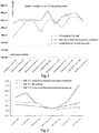
Figs. 1 and 2 are schematic graphs showing the influence of on-line movable insulation on steel coil performances. -
Fig. 3 is a schematic view of an embodiment of a hot-rolled strip steel heat treatment line according to the present disclosure. -
Fig. 4 is a schematic view of an embodiment of a hot-rolled strip steel heat treatment line according to the present disclosure. -
Fig. 5 is a schematic view of an embodiment of a hot-rolled strip steel heat treatment line according to the present disclosure. -
Fig. 6 is a schematic view showing the structure of a movable hot coil thermal insulation heat treatment device in Example 1 according to the present disclosure. -
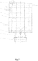
Fig. 7 is a side view of the movable hot coil thermal insulation heat treatment device in Example 1 according to the present disclosure. -
Fig. 8 is a front view of the movable hot coil thermal insulation heat treatment device in Example 2 according to the present disclosure. -
Fig. 9 is a front view of the movable hot coil thermal insulation heat treatment device in Example 3 according to the present disclosure. -
Fig. 10 is a partial cutaway view of the thermal insulation enclosure in the movable hot coil thermal insulation heat treatment device in the Examples according to the present disclosure. -
Fig. 11 is a stereogram of the movable hot coil thermal insulation heat treatment device in Example 1 according to the present disclosure. -
Fig. 12 is a front view of the movable hot coil thermal insulation heat treatment device in Example 1 according to the present disclosure. -
Fig. 13 is a stereogram of the bottom sealing device in the movable hot coil thermal insulation heat treatment device in Example 1 according to the present disclosure. -
Fig. 14 is a front view of the movable hot coil thermal insulation heat treatment device in Example 1 according to the present disclosure. -
Fig. 15 is a side view of the device shown inFig. 14 . -
Fig. 16 is an upward stereogram of the movable hot coil thermal insulation heat treatment device in Example 1 according to the present disclosure. -
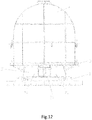
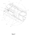
Fig. 17 is an enlarged schematic view of part A inFig. 16 . - A hot-rolling on-line movable thermal insulation heat treatment process is provided according to the present disclosure, wherein a slab is heated, rolled, laminar-flow cooled, and coiled to a hot coil state; after the hot coil is unloaded and bundled, a movable hot coil thermal insulation heat treatment device is applied to the hot coil within 30 minutes to start heat treatment on the hot coil while the hot coil is simultaneously transported on-line to a hot coil thermal insulation treatment zone; after heat treatment for a period of time of 1 to 48 hours, the steel coil is cooled in air and then sent to a warehouse, wherein a coiling temperature is controlled between 250 °C and 750 °C.
- Preferably, the movable hot coil thermal insulation heat treatment device is applied to the hot coil within 10 minutes after the coiling is completed.
- Preferably, the movable hot coil thermal insulation heat treatment device is a transport cart with a thermal insulation enclosure.
- Preferably, a natural cooling rate in the movable hot coil thermal insulation heat treatment device is from 1 to 10 °C/h.
- Preferably, a heating system and/or a vacuuming system and/or an inert gas filling system are provided in the movable hot coil thermal insulation heat treatment device.
- Referring to
Figs. 1 and 2 , according to the present disclosure, the thermal insulation heat treatment of hot-rolled and cold-rolled high-strength steel hot coils in an "on-line mode" avoids the influence of air cooling after coiling on the performances of the steel coils, and improves the performances of the hot-rolled and cold-rolled high-strength steel. - Referring to
Fig. 3 , according to the present disclosure, there is provided a hot-rolled strip steel heat treatment line, wherein a heat treatment transportchain roller bed 30 is provided between a bundlingdevice 20 downstream of a hot-rolledsteel coiler 10 and a cold rolling set; at least one movable hot coil thermal insulationheat treatment device 40 is provided on the heat treatment transportchain roller bed 30; correspondingly, hoistingdevices 50, 50' capable of loading and unloading a steel coil to the movable hot coil thermal insulation heat treatment device are positioned respectively at two ends of the heat treatment transportchain roller bed 30; and a thermal insulation enclosure for closed on-line thermal insulation of the hot-rolled steel coil is provided on the movable hot coil thermal insulationheat treatment device 40. - Referring to
Fig. 4 , at least one heat treatment work station 80 is provided on the heat treatment transportchain roller bed 30 or the thermal insulation transport chain roller bed 70; a heating system for heating an interior of the thermal insulation enclosure in the movable hot coil thermal insulation heat treatment device and/or a protective cooling gas input system for gas cooling are provided in the heat treatment work station 80; 90 represents a rotating roller bed. - Referring to
Fig. 5 , a steel coil thermal insulation zone 60 is provided on one side of the heat treatment transportchain roller bed 10, wherein at least one thermal insulation transport chain roller bed 70 coupled to the heat treatment transport chain roller bed 70 and ahoisting device 50" are provided in the steel coil thermal insulation zone 60. - Referring to
Fig. 5 , an information code printing device 90 for printing steel coil information on the steel coil is provided at one end of the heat treatment transportchain roller bed 30 facing the cold rolling set. - Referring to
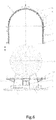
Figs. 5-17 , the movable hot coil thermal insulationheat treatment device 40 according to the present disclosure comprises: - a
baseboard 1; - a
steel coil fixture 2 provided at a central portion of an upper end surface of thebaseboard 1; - a
tray 3 having an annular structure, wherein thetray 3 is horizontally arranged by nesting at a middle part of thesteel coil fixture 2; - a
thermal insulation enclosure 4, which has an open lower end and an inner chamber having a volume larger than asteel coil 100, wherein thethermal insulation enclosure 4 is arranged on thetray 3; - an
electric heating device 5 provided on an inner side wall of thethermal insulation enclosure 4; - a temperature sensor 6 provided in the
thermal insulation enclosure 4; and - an information acquisition control module 7, wherein the
electric heating device 5 and the temperature sensor 6 are electrically coupled to the information acquisition control module 7. - Further, it further comprises a gas protection device and gas sensors 8, 8' which are electrically coupled to the information acquisition control module 7, respectively.
- Preferably, a signal emitting module is provided in the information acquisition control module 7.
- Preferably, the
steel coil fixture 2 comprises two juxtaposedsupport bodies support bodies support bodies support bodies - Still further, a
bottom sealing device 11 is arranged between bottoms of the twosupport bodies steel coil fixture 2 to close the gap between the bottoms of the twosupport bodies - Preferably, the
bottom sealing device 11 comprises: - a support plate 111 provided between the two
support bodies steel coil fixture 2, wherein the support plate 111 is arranged vertically, and a plurality ofrollers 112 are provided on lower parts of two sides of the support plate 111 at even spacings in a length direction to form a slidable mechanism; and - a sealing
plate 113 provided horizontally on a top surface of the support plate 111, wherein the sealing plate has a size corresponding to the gap between the bottoms of the twosupport bodies - Preferably, the sealing
plate 113 has a composite layered structure, wherein an intermediate part of the structure is consisting of an insulating felt, and two side parts are high temperature resistant steel plates. - Preferably, an
electromagnetic block 114 is provided on an end face of the support plate 111, and correspondingly, a metal stopper matching theelectromagnetic block 114 is provided between end portions of the twosupport bodies steel coil fixture 2 at one side. - Referring to
Figs. 15-17 , the side sealing device 9 (which is taken as an example; the same below) comprises: - two fixed baseboards 91, 91' respectively provided horizontally at a bottom of the gap at an outer side of the two
support bodies steel coil fixture 2, wherein a plurality ofguide rollers 92, 92' spaced in an axial direction are provided on an outer side surface of the fixed baseboards 91, 91'; - two sealing members 93, 93' respectively arranged at the gap at two sides of the two
support bodies steel coil fixture 2, wherein bottom ends of the sealing members 93, 93' are provided slidably on theguide rollers 92, 92' of the fixed baseboard 91; - a
driving mechanism 94, comprising:- two racks 941 respectively provided horizontally on the two sealing members 93, 93' with one end of the rack 941 being coupled to the sealing members 93, 93';
- a
drive shaft 942, arranged horizontally at a side of thesupport body 21 opposite to the gap through two bearingpedestals 943, wherein a gear 944 is provided at each of two ends of thedrive shaft 942, wherein thegear 943 meshes with the rack 941.
- Preferably, the bearing
pedestal 943 is provided on one side of the support body 221 by using a fixing plate 944, wherein one side of the fixingplate 945 is provided with a throughhole 9451 for the rack 941 to pass through, and aroller 946 abutted against a top surface of the rack 941 is provided at an outer side of the fixingplate 945 above the throughhole 945. - Preferably, the sealing member 93 has a composite layered structure, wherein an intermediate part of the structure is an insulating material, and two sides of the intermediate part are cladded with a high temperature resistant steel plate.
- Preferably, the sealing member 93 is a right angle plate structure.
- Preferably, a
positioning sleeve 12 is provided on a lower part of a side of thethermal insulation enclosure 4. Correspondingly, a positioning pin 13 matching thepositioning sleeve 12 is provided on thetray 3 for the thermal insulation enclosure. The positioning pin 13 is preferably a cone-shaped body. - Preferably, the
thermal insulation enclosure 4 is provided with a ventilation hole and acorresponding exhaust valve 41. - Preferably, the
thermal insulation enclosure 4 has a composite structure, comprising: an outer protection layer, which is a high-strength steel plate; an intermediate layer, which is a thermal insulation material; and an inner layer, which is a high temperature resistant stainless steel plate. - Preferably, the
thermal insulation enclosure 4 is a composite structure, comprising an inner radiation layer 42, an electric heating wire layer 43, anintermediate mesh cover 44, an intermediatethermal insulation layer 45, and anouter protection layer 46 in order from inside to outside. The composite structure of the thermal insulation enclosure is fixed with an anchor nail 47. - Referring to
Figs. 5 and6 , thethermal insulation enclosure 4 is a square thermal insulation enclosure or a circular thermal insulation enclosure. - Preferably, the
electric heating device 5 is an electric heating wire, and the temperature sensor 6 is a thermocouple sensor. - The thermal insulation treatment of a strip steel coil after coiling according to the present disclosure also fulfils the purpose of annealing treatment by making use of the residual heat in the steel coil that has just been coiled, which greatly addresses the challenges of insufficient performance improvement caused by the excessively long time from coiling to entry of the steel coil to the slow cooling device, and large performance fluctuation of the strip steel in the length and width directions.
- A special batch of hot-rolled strip steel may need to be subjected to special treatment such as in-depth processing. The heating device and protective cooling gas input system provided in the thermal insulation enclosure can cooperate to achieve temperature control under necessary conditions.
Claims (24)
- A hot-rolling on-line movable thermal insulation heat treatment process, wherein a slab is heated, rolled, laminar-flow cooled, and coiled to a hot coil state; after the hot coil is unloaded and bundled, a movable hot coil thermal insulation heat treatment device is applied to the hot coil within 30 minutes to start heat treatment on the hot coil while the hot coil is simultaneously transported on-line to a hot coil thermal insulation treatment zone; after heat treatment for a period of time of 1 to 48 hours, the steel coil is cooled in air and then sent to a warehouse, wherein a coiling temperature is controlled between 250 °C and 750 °C.
- The hot-rolling on-line movable thermal insulation heat treatment process according to claim 1, wherein the movable hot coil thermal insulation heat treatment device is applied to the hot coil within 10 minutes after the coiling is completed.
- The hot-rolling on-line movable thermal insulation heat treatment process according to claim 1, wherein the movable hot coil thermal insulation heat treatment device is a transport cart with a thermal insulation enclosure.
- The hot-rolling on-line movable thermal insulation heat treatment process according to claim 1, wherein a natural cooling rate within the movable hot coil thermal insulation heat treatment device is from 1 to 10 °C/h.
- The hot-rolling on-line movable thermal insulation heat treatment process according to claim 1 or 2 or 3, wherein a heating system and/or a vacuuming system and/or an inert gas filling system are provided in the movable hot coil thermal insulation heat treatment device.
- A hot-rolling on-line movable thermal insulation heat treatment line, wherein a heat treatment transport chain roller bed is provided between a bundling device downstream of a hot-rolled steel coiler and a cold rolling set; at least one movable hot coil thermal insulation heat treatment device is positioned on the heat treatment transport chain roller bed; correspondingly, a hoisting device capable of loading and unloading a steel coil to the movable hot coil thermal insulation heat treatment device is positioned at each end of the heat treatment transport chain roller bed; and a thermal insulation enclosure for closed on-line thermal insulation of the hot-rolled steel coil is positioned on the movable hot coil thermal insulation heat treatment device.
- The hot-rolling on-line movable thermal insulation heat treatment line according to claim 6, wherein a steel coil thermal insulation zone is provided at one side of the heat treatment transport chain roller bed, and at least one thermal insulation transport chain roller bed coupled to the heat treatment transport chain roller bed is provided in the steel coil thermal insulation zone.
- The hot-rolling on-line movable thermal insulation heat treatment line according to claim 6, wherein at least one heat treatment work station is provided on the heat treatment transport chain roller bed or the thermal insulation transport chain roller bed, and a heating system for heating an interior of the thermal insulation enclosure in the movable hot coil thermal insulation heat treatment device and/or a protective cooling gas input system for gas cooling are provided in the heat treatment work station.
- The hot-rolling on-line movable thermal insulation heat treatment line according to claim 6, wherein an information code printing device for printing steel coil information on the steel coil is provided at one end of the heat treatment transport chain roller bed facing the cold rolling set.
- The hot-rolling on-line movable thermal insulation heat treatment line according to claim 6 or 8, wherein the movable hot coil thermal insulation heat treatment device comprises:a baseboard;a steel coil fixture provided at a central portion of an upper end surface of the baseboard;a tray which is an annular structure and horizontally arranged by nesting at a middle part of the steel coil fixture;a thermal insulation enclosure, which has an open lower end and an inner chamber having a volume larger than a steel coil, wherein the thermal insulation enclosure is arranged on the tray;an electric heating device provided on an inner side wall of the thermal insulation enclosure;a temperature sensor provided in the thermal insulation enclosure; andan information acquisition control module, wherein the electric heating device and the temperature sensor are electrically coupled to the information acquisition control module.
- The hot-rolling on-line movable thermal insulation heat treatment line according to claim 10, wherein the movable hot coil thermal insulation heat treatment device further comprises a gas protection device and a gas sensor which are electrically coupled to the information acquisition control module, respectively.
- The hot-rolling on-line movable thermal insulation heat treatment line according to claim 10, wherein a signal emitting module is provided in the information acquisition control module.
- The hot-rolling on-line movable thermal insulation heat treatment line according to claim 10, wherein the steel coil fixture comprises two juxtaposed support bodies, wherein upper end faces of the two support bodies are inclined surfaces and are arranged symmetrically; and a side sealing device is arranged at a gap at each of two sides of the two support bodies.
- The hot-rolling on-line movable thermal insulation heat treatment line according to claim 10, wherein a bottom sealing device is arranged between bottoms of the two support bodies of the steel coil fixture to close the gap between the bottoms of the two support bodies.
- The hot-rolling on-line movable thermal insulation heat treatment line according to claim 14, wherein the bottom sealing device comprises:a support plate provided between the two support bodies of the steel coil fixture, wherein the support plate is arranged vertically, and a plurality of rollers are provided on lower parts of two sides of the support plate at even spacings in a length direction to form a slidable mechanism; anda sealing plate provided horizontally on a top surface of the support plate, wherein the sealing plate has a size corresponding to the gap between the bottoms of the two support bodies.
- The hot-rolling on-line movable thermal insulation heat treatment line according to claim 15, wherein an electromagnetic block is provided on an end face of the support plate, and correspondingly, a metal stopper matching the electromagnetic block is provided between end portions of the two support bodies of the steel coil fixture at one side.
- The hot-rolling on-line movable thermal insulation heat treatment line according to claim 13, wherein the side sealing device comprises:two fixed baseboards each provided horizontally at a bottom of the gap at an outer side of the two support bodies of the steel coil fixture, wherein a plurality of guide rollers spaced in an axial direction are provided on an outer side surface of each of the fixed baseboards;two sealing members, each arranged at the gap at one of the two sides of the two support bodies of the steel coil fixture, wherein a bottom end of the sealing member is provided slidably on the guide rollers of the fixed baseboard; anda driving mechanism, comprising:two racks, each provided horizontally on one of the two sealing members with one end of the rack being coupled to the seal member; anda drive shaft, arranged horizontally at a side of the support body opposite to the gap through two bearing pedestals; two gears, each provided at one of two ends of the drive shaft, wherein the gear meshes with the rack.
- The hot-rolling on-line movable thermal insulation heat treatment line according to claim 17, wherein the bearing pedestal is provided on one side of the support body by using a fixing plate, wherein one side of the fixing plate is provided with a through hole for the rack to pass through, and a roller abutted against a top surface of the rack is provided at an outer side of the fixing plate above the through hole.
- The hot-rolling on-line movable thermal insulation heat treatment line according to claim 15 or 17, wherein the sealing plate and the sealing member have a composite layered structure, wherein an intermediate part of the structure is an insulating felt, and two sides of the intermediate part are cladded with a high temperature resistant steel plate.
- The hot-rolling on-line movable thermal insulation heat treatment line according to claim 10, wherein a positioning sleeve is provided on a lower part of a side of the thermal insulation enclosure; correspondingly, a positioning pin matching the positioning sleeve is provided on the tray for the thermal insulation enclosure; the positioning pin is preferably a cone-shaped body.
- The hot-rolling on-line movable thermal insulation heat treatment line according to claim 10 or 20, wherein the thermal insulation enclosure is provided with a ventilation hole and a corresponding exhaust valve.
- The hot-rolling on-line movable thermal insulation heat treatment line according to claim 10 or 20 or 21, wherein the thermal insulation enclosure has a composite structure, comprising: an outer protection layer, which is a high-strength steel plate; an intermediate layer, which is a thermal insulation material; and an inner layer, which is a high temperature resistant stainless steel plate.
- The hot-rolling on-line movable thermal insulation heat treatment line according to claim 10 or 20 or 21, wherein the thermal insulation enclosure is a composite structure, comprising an inner radiation layer, an electric heating wire layer, an intermediate mesh cover, an intermediate thermal insulation layer, and an outer protection layer in order from inside to outside.
- The hot-rolling on-line movable thermal insulation heat treatment line according to claim 10, wherein the electric heating device is an electric heating wire, and the temperature sensor is a thermocouple sensor.
Applications Claiming Priority (4)
| Application Number | Priority Date | Filing Date | Title |
|---|---|---|---|
| CN201710853613.3A CN107470377A (en) | 2017-09-20 | 2017-09-20 | Steel band manufacture streamline is incubated annealing device online |
| CN201810632238.4A CN110616307A (en) | 2018-06-19 | 2018-06-19 | Hot rolling strip steel heat treatment line |
| CN201810632237.XA CN110616306A (en) | 2018-06-19 | 2018-06-19 | Hot rolling on-line mobile heat preservation heat treatment process |
| PCT/CN2018/106709 WO2019057116A1 (en) | 2017-09-20 | 2018-09-20 | Hot-rolling online movable thermal insulation heat treatment process, and heat treatment line |
Publications (3)
| Publication Number | Publication Date |
|---|---|
| EP3685931A1 true EP3685931A1 (en) | 2020-07-29 |
| EP3685931A4 EP3685931A4 (en) | 2021-08-11 |
| EP3685931B1 EP3685931B1 (en) | 2023-08-23 |
Family
ID=65810629
Family Applications (1)
| Application Number | Title | Priority Date | Filing Date |
|---|---|---|---|
| EP18859703.3A Active EP3685931B1 (en) | 2017-09-20 | 2018-09-20 | Hot-rolling online movable thermal insulation heat treatment process, and heat treatment line |
Country Status (4)
| Country | Link |
|---|---|
| EP (1) | EP3685931B1 (en) |
| JP (1) | JP7253558B2 (en) |
| KR (1) | KR20200066630A (en) |
| WO (1) | WO2019057116A1 (en) |
Families Citing this family (3)
| Publication number | Priority date | Publication date | Assignee | Title |
|---|---|---|---|---|
| CN113355496B (en) * | 2021-06-04 | 2022-09-13 | 东北大学 | On-line solution annealing process for rolling waste heat of stainless steel hot-rolled coil |
| JP7687195B2 (en) * | 2021-11-17 | 2025-06-03 | 大同特殊鋼株式会社 | Steel manufacturing method and manufacturing equipment |
| CN116692296A (en) * | 2023-06-25 | 2023-09-05 | 中冶华天工程技术有限公司 | Modular thermal insulation equipment |
Family Cites Families (20)
| Publication number | Priority date | Publication date | Assignee | Title |
|---|---|---|---|---|
| RO75367A (en) * | 1977-11-25 | 1980-11-30 | Alleghany Ludlum Industries,Inc.,Us | OVEN FOR REINFORCING GLENE-SHAPED METAL BANDS |
| JPS5837128A (en) * | 1981-08-26 | 1983-03-04 | Nippon Kokan Kk <Nkk> | Manufacture of al killed steel plate for continuous annealing |
| JPS60110816A (en) * | 1983-11-17 | 1985-06-17 | Nippon Steel Corp | Softening method of hot rolled steel strip |
| JPS60125329A (en) * | 1983-12-07 | 1985-07-04 | Kawasaki Steel Corp | Production of hot rolled steel strip |
| JPS60218431A (en) * | 1984-04-12 | 1985-11-01 | Sumitomo Metal Ind Ltd | Method for cooling coil of host steel strip |
| JPS61159534A (en) * | 1985-01-05 | 1986-07-19 | Nippon Steel Corp | Manufacture of hot rolled steel strip for electric welded steel pipe |
| JP3449310B2 (en) | 1999-09-02 | 2003-09-22 | Jfeスチール株式会社 | Method for producing hot-rolled steel sheet with excellent pickling properties and uniformity of coil material |
| JP3744279B2 (en) * | 1999-09-09 | 2006-02-08 | Jfeスチール株式会社 | Method for producing high carbon hot-rolled steel sheet with excellent scale adhesion |
| US20020076289A1 (en) * | 2000-12-15 | 2002-06-20 | National Steel Car Limited | Insulated triple trough coil car |
| CN101413051B (en) | 2008-06-20 | 2010-11-17 | 北京首钢国际工程技术有限公司 | On-line heat treatment wire collecting and conveying system |
| JP5546118B2 (en) | 2008-10-16 | 2014-07-09 | 株式会社神戸製鋼所 | Coil slow cooling device |
| CN202316643U (en) * | 2011-11-14 | 2012-07-11 | 天津市中重科技工程有限公司 | Double-station coreless transfer type hot coil box |
| CN103057842A (en) * | 2013-01-15 | 2013-04-24 | 无锡亚中智能装备有限公司 | Vehicle-mounted silicon steel coil thermostat |
| CN203064459U (en) * | 2013-01-15 | 2013-07-17 | 无锡亚中智能装备有限公司 | Vehicle-mounted type silicon steel coil constant temperature device |
| CN203497055U (en) * | 2013-09-23 | 2014-03-26 | 上海宝冶集团有限公司 | Bidirectional thermal-insulation trailer |
| CN104087839B (en) * | 2014-07-18 | 2016-05-25 | 武汉钢铁(集团)公司 | The ultra-thin laser weld steel for saw blade substrate of hot rolling and production method |
| KR101589913B1 (en) | 2014-12-10 | 2016-02-01 | 주식회사 포스코 | Heat treating method for advanced high strength steel hot coil and cold rolling method using the same |
| CN206447906U (en) * | 2017-01-05 | 2017-08-29 | 鞍钢集团工程技术有限公司 | Between a kind of portable slow cooling |
| CN107470377A (en) * | 2017-09-20 | 2017-12-15 | 上海贺力液压机电有限公司 | Steel band manufacture streamline is incubated annealing device online |
| CN207170521U (en) * | 2017-09-20 | 2018-04-03 | 上海贺力液压机电有限公司 | Steel band manufacture streamline is incubated annealing device online |
-
2018
- 2018-09-20 WO PCT/CN2018/106709 patent/WO2019057116A1/en not_active Ceased
- 2018-09-20 EP EP18859703.3A patent/EP3685931B1/en active Active
- 2018-09-20 KR KR1020207010727A patent/KR20200066630A/en not_active Ceased
- 2018-09-20 JP JP2020537826A patent/JP7253558B2/en active Active
Also Published As
| Publication number | Publication date |
|---|---|
| KR20200066630A (en) | 2020-06-10 |
| EP3685931A4 (en) | 2021-08-11 |
| WO2019057116A1 (en) | 2019-03-28 |
| JP7253558B2 (en) | 2023-04-06 |
| EP3685931B1 (en) | 2023-08-23 |
| JP2020534440A (en) | 2020-11-26 |
Similar Documents
| Publication | Publication Date | Title |
|---|---|---|
| WO2017167147A1 (en) | Heating equipment for use in hot forming process, and hot forming production line | |
| CN112872064B (en) | A low-carbon hot-rolled narrow-strip steel scale control process for pickling | |
| EP3685931B1 (en) | Hot-rolling online movable thermal insulation heat treatment process, and heat treatment line | |
| CN111346914A (en) | A kind of hot rolling process method for improving the surface quality of automobile outer plate | |
| KR102397795B1 (en) | Movable Hot Rolling Thermal Insulation Heat Treatment Equipment | |
| CN212444119U (en) | Production system of aluminum alloy coiled material/plate | |
| CN108441621A (en) | A kind of movable type hot rolling heat preservation hot processing unit | |
| CN102658301A (en) | Control and modifying unit of scale of hot rolling strip steel | |
| CN201744485U (en) | System for producing wide and heavy plate products | |
| JP6583638B2 (en) | Technology to diffuse aluminum silicon into the steel plate surface | |
| JP6260448B2 (en) | Heat treatment equipment for hot-rolled steel strip | |
| CN108559834A (en) | A kind of fixed hot rolling heat preservation annealing device | |
| CN105414177B (en) | A kind of cold rolling super-high strength steel short route production and processing technology and equipment | |
| CN110614281A (en) | Method for improving iron scale adhesion of hot-rolled black steel product | |
| CN208616737U (en) | A kind of travelling bogie with insulation cover | |
| JP6952197B2 (en) | Fixed hot coil heat insulation heat treatment equipment | |
| CN208617953U (en) | A kind of fixed hot rolling heat preservation annealing device | |
| CN214142444U (en) | Movable hot coil annealing device | |
| CN114214485B (en) | One-fire hot charging heat treatment process for ferrite stainless steel hot-rolled plate | |
| CN101509726B (en) | Veneer heating apparatus and veneer heating production line | |
| JP2016148063A (en) | Manufacturing method and processing facility for high-strength steel sheet | |
| CN112899457B (en) | Heat treatment method capable of replacing high-magnetic induction oriented silicon steel normalizing annealing | |
| CN110616299A (en) | Production method of high-strength steel | |
| CN110616307A (en) | Hot rolling strip steel heat treatment line | |
| CN110616306A (en) | Hot rolling on-line mobile heat preservation heat treatment process |
Legal Events
| Date | Code | Title | Description |
|---|---|---|---|
| STAA | Information on the status of an ep patent application or granted ep patent |
Free format text: STATUS: THE INTERNATIONAL PUBLICATION HAS BEEN MADE |
|
| PUAI | Public reference made under article 153(3) epc to a published international application that has entered the european phase |
Free format text: ORIGINAL CODE: 0009012 |
|
| STAA | Information on the status of an ep patent application or granted ep patent |
Free format text: STATUS: REQUEST FOR EXAMINATION WAS MADE |
|
| 17P | Request for examination filed |
Effective date: 20200324 |
|
| AK | Designated contracting states |
Kind code of ref document: A1 Designated state(s): AL AT BE BG CH CY CZ DE DK EE ES FI FR GB GR HR HU IE IS IT LI LT LU LV MC MK MT NL NO PL PT RO RS SE SI SK SM TR |
|
| AX | Request for extension of the european patent |
Extension state: BA ME |
|
| DAV | Request for validation of the european patent (deleted) | ||
| DAX | Request for extension of the european patent (deleted) | ||
| REG | Reference to a national code |
Ref country code: DE Ipc: C21D0009520000 Ref country code: DE Ref legal event code: R079 Ref document number: 602018056129 Country of ref document: DE Free format text: PREVIOUS MAIN CLASS: B21B0045000000 Ipc: C21D0009520000 |
|
| A4 | Supplementary search report drawn up and despatched |
Effective date: 20210712 |
|
| RIC1 | Information provided on ipc code assigned before grant |
Ipc: C21D 9/52 20060101AFI20210706BHEP Ipc: B21B 1/26 20060101ALI20210706BHEP Ipc: C21D 1/22 20060101ALI20210706BHEP Ipc: C21D 1/84 20060101ALI20210706BHEP Ipc: C21D 8/02 20060101ALI20210706BHEP Ipc: F27B 11/00 20060101ALI20210706BHEP Ipc: C21D 9/00 20060101ALI20210706BHEP Ipc: C21D 9/673 20060101ALI20210706BHEP Ipc: C21D 9/675 20060101ALI20210706BHEP Ipc: C21D 9/677 20060101ALI20210706BHEP Ipc: B21B 45/00 20060101ALI20210706BHEP |
|
| GRAP | Despatch of communication of intention to grant a patent |
Free format text: ORIGINAL CODE: EPIDOSNIGR1 |
|
| STAA | Information on the status of an ep patent application or granted ep patent |
Free format text: STATUS: GRANT OF PATENT IS INTENDED |
|
| INTG | Intention to grant announced |
Effective date: 20230303 |
|
| GRAS | Grant fee paid |
Free format text: ORIGINAL CODE: EPIDOSNIGR3 |
|
| GRAA | (expected) grant |
Free format text: ORIGINAL CODE: 0009210 |
|
| STAA | Information on the status of an ep patent application or granted ep patent |
Free format text: STATUS: THE PATENT HAS BEEN GRANTED |
|
| AK | Designated contracting states |
Kind code of ref document: B1 Designated state(s): AL AT BE BG CH CY CZ DE DK EE ES FI FR GB GR HR HU IE IS IT LI LT LU LV MC MK MT NL NO PL PT RO RS SE SI SK SM TR |
|
| REG | Reference to a national code |
Ref country code: GB Ref legal event code: FG4D |
|
| REG | Reference to a national code |
Ref country code: CH Ref legal event code: EP |
|
| REG | Reference to a national code |
Ref country code: IE Ref legal event code: FG4D |
|
| REG | Reference to a national code |
Ref country code: DE Ref legal event code: R096 Ref document number: 602018056129 Country of ref document: DE |
|
| REG | Reference to a national code |
Ref country code: LT Ref legal event code: MG9D |
|
| REG | Reference to a national code |
Ref country code: NL Ref legal event code: MP Effective date: 20230823 |
|
| REG | Reference to a national code |
Ref country code: AT Ref legal event code: MK05 Ref document number: 1602666 Country of ref document: AT Kind code of ref document: T Effective date: 20230823 |
|
| PG25 | Lapsed in a contracting state [announced via postgrant information from national office to epo] |
Ref country code: GR Free format text: LAPSE BECAUSE OF FAILURE TO SUBMIT A TRANSLATION OF THE DESCRIPTION OR TO PAY THE FEE WITHIN THE PRESCRIBED TIME-LIMIT Effective date: 20231124 |
|
| PG25 | Lapsed in a contracting state [announced via postgrant information from national office to epo] |
Ref country code: IS Free format text: LAPSE BECAUSE OF FAILURE TO SUBMIT A TRANSLATION OF THE DESCRIPTION OR TO PAY THE FEE WITHIN THE PRESCRIBED TIME-LIMIT Effective date: 20231223 |
|
| PG25 | Lapsed in a contracting state [announced via postgrant information from national office to epo] |
Ref country code: SE Free format text: LAPSE BECAUSE OF FAILURE TO SUBMIT A TRANSLATION OF THE DESCRIPTION OR TO PAY THE FEE WITHIN THE PRESCRIBED TIME-LIMIT Effective date: 20230823 Ref country code: RS Free format text: LAPSE BECAUSE OF FAILURE TO SUBMIT A TRANSLATION OF THE DESCRIPTION OR TO PAY THE FEE WITHIN THE PRESCRIBED TIME-LIMIT Effective date: 20230823 Ref country code: PT Free format text: LAPSE BECAUSE OF FAILURE TO SUBMIT A TRANSLATION OF THE DESCRIPTION OR TO PAY THE FEE WITHIN THE PRESCRIBED TIME-LIMIT Effective date: 20231226 Ref country code: NO Free format text: LAPSE BECAUSE OF FAILURE TO SUBMIT A TRANSLATION OF THE DESCRIPTION OR TO PAY THE FEE WITHIN THE PRESCRIBED TIME-LIMIT Effective date: 20231123 Ref country code: NL Free format text: LAPSE BECAUSE OF FAILURE TO SUBMIT A TRANSLATION OF THE DESCRIPTION OR TO PAY THE FEE WITHIN THE PRESCRIBED TIME-LIMIT Effective date: 20230823 Ref country code: LV Free format text: LAPSE BECAUSE OF FAILURE TO SUBMIT A TRANSLATION OF THE DESCRIPTION OR TO PAY THE FEE WITHIN THE PRESCRIBED TIME-LIMIT Effective date: 20230823 Ref country code: LT Free format text: LAPSE BECAUSE OF FAILURE TO SUBMIT A TRANSLATION OF THE DESCRIPTION OR TO PAY THE FEE WITHIN THE PRESCRIBED TIME-LIMIT Effective date: 20230823 Ref country code: IS Free format text: LAPSE BECAUSE OF FAILURE TO SUBMIT A TRANSLATION OF THE DESCRIPTION OR TO PAY THE FEE WITHIN THE PRESCRIBED TIME-LIMIT Effective date: 20231223 Ref country code: HR Free format text: LAPSE BECAUSE OF FAILURE TO SUBMIT A TRANSLATION OF THE DESCRIPTION OR TO PAY THE FEE WITHIN THE PRESCRIBED TIME-LIMIT Effective date: 20230823 Ref country code: GR Free format text: LAPSE BECAUSE OF FAILURE TO SUBMIT A TRANSLATION OF THE DESCRIPTION OR TO PAY THE FEE WITHIN THE PRESCRIBED TIME-LIMIT Effective date: 20231124 Ref country code: FI Free format text: LAPSE BECAUSE OF FAILURE TO SUBMIT A TRANSLATION OF THE DESCRIPTION OR TO PAY THE FEE WITHIN THE PRESCRIBED TIME-LIMIT Effective date: 20230823 Ref country code: AT Free format text: LAPSE BECAUSE OF FAILURE TO SUBMIT A TRANSLATION OF THE DESCRIPTION OR TO PAY THE FEE WITHIN THE PRESCRIBED TIME-LIMIT Effective date: 20230823 |
|
| PG25 | Lapsed in a contracting state [announced via postgrant information from national office to epo] |
Ref country code: PL Free format text: LAPSE BECAUSE OF FAILURE TO SUBMIT A TRANSLATION OF THE DESCRIPTION OR TO PAY THE FEE WITHIN THE PRESCRIBED TIME-LIMIT Effective date: 20230823 |
|
| PG25 | Lapsed in a contracting state [announced via postgrant information from national office to epo] |
Ref country code: ES Free format text: LAPSE BECAUSE OF FAILURE TO SUBMIT A TRANSLATION OF THE DESCRIPTION OR TO PAY THE FEE WITHIN THE PRESCRIBED TIME-LIMIT Effective date: 20230823 |
|
| PG25 | Lapsed in a contracting state [announced via postgrant information from national office to epo] |
Ref country code: SM Free format text: LAPSE BECAUSE OF FAILURE TO SUBMIT A TRANSLATION OF THE DESCRIPTION OR TO PAY THE FEE WITHIN THE PRESCRIBED TIME-LIMIT Effective date: 20230823 Ref country code: RO Free format text: LAPSE BECAUSE OF FAILURE TO SUBMIT A TRANSLATION OF THE DESCRIPTION OR TO PAY THE FEE WITHIN THE PRESCRIBED TIME-LIMIT Effective date: 20230823 Ref country code: ES Free format text: LAPSE BECAUSE OF FAILURE TO SUBMIT A TRANSLATION OF THE DESCRIPTION OR TO PAY THE FEE WITHIN THE PRESCRIBED TIME-LIMIT Effective date: 20230823 Ref country code: EE Free format text: LAPSE BECAUSE OF FAILURE TO SUBMIT A TRANSLATION OF THE DESCRIPTION OR TO PAY THE FEE WITHIN THE PRESCRIBED TIME-LIMIT Effective date: 20230823 Ref country code: DK Free format text: LAPSE BECAUSE OF FAILURE TO SUBMIT A TRANSLATION OF THE DESCRIPTION OR TO PAY THE FEE WITHIN THE PRESCRIBED TIME-LIMIT Effective date: 20230823 Ref country code: CZ Free format text: LAPSE BECAUSE OF FAILURE TO SUBMIT A TRANSLATION OF THE DESCRIPTION OR TO PAY THE FEE WITHIN THE PRESCRIBED TIME-LIMIT Effective date: 20230823 Ref country code: SK Free format text: LAPSE BECAUSE OF FAILURE TO SUBMIT A TRANSLATION OF THE DESCRIPTION OR TO PAY THE FEE WITHIN THE PRESCRIBED TIME-LIMIT Effective date: 20230823 |
|
| REG | Reference to a national code |
Ref country code: CH Ref legal event code: PL |
|
| PG25 | Lapsed in a contracting state [announced via postgrant information from national office to epo] |
Ref country code: LU Free format text: LAPSE BECAUSE OF NON-PAYMENT OF DUE FEES Effective date: 20230920 |
|
| REG | Reference to a national code |
Ref country code: DE Ref legal event code: R097 Ref document number: 602018056129 Country of ref document: DE |
|
| REG | Reference to a national code |
Ref country code: BE Ref legal event code: MM Effective date: 20230930 |
|
| PG25 | Lapsed in a contracting state [announced via postgrant information from national office to epo] |
Ref country code: MC Free format text: LAPSE BECAUSE OF FAILURE TO SUBMIT A TRANSLATION OF THE DESCRIPTION OR TO PAY THE FEE WITHIN THE PRESCRIBED TIME-LIMIT Effective date: 20230823 Ref country code: LU Free format text: LAPSE BECAUSE OF NON-PAYMENT OF DUE FEES Effective date: 20230920 |
|
| PLBE | No opposition filed within time limit |
Free format text: ORIGINAL CODE: 0009261 |
|
| STAA | Information on the status of an ep patent application or granted ep patent |
Free format text: STATUS: NO OPPOSITION FILED WITHIN TIME LIMIT |
|
| REG | Reference to a national code |
Ref country code: IE Ref legal event code: MM4A |
|
| PG25 | Lapsed in a contracting state [announced via postgrant information from national office to epo] |
Ref country code: IE Free format text: LAPSE BECAUSE OF NON-PAYMENT OF DUE FEES Effective date: 20230920 |
|
| PG25 | Lapsed in a contracting state [announced via postgrant information from national office to epo] |
Ref country code: CH Free format text: LAPSE BECAUSE OF NON-PAYMENT OF DUE FEES Effective date: 20230930 |
|
| GBPC | Gb: european patent ceased through non-payment of renewal fee |
Effective date: 20231123 |
|
| 26N | No opposition filed |
Effective date: 20240524 |
|
| PG25 | Lapsed in a contracting state [announced via postgrant information from national office to epo] |
Ref country code: IE Free format text: LAPSE BECAUSE OF NON-PAYMENT OF DUE FEES Effective date: 20230920 Ref country code: CH Free format text: LAPSE BECAUSE OF NON-PAYMENT OF DUE FEES Effective date: 20230930 Ref country code: SI Free format text: LAPSE BECAUSE OF FAILURE TO SUBMIT A TRANSLATION OF THE DESCRIPTION OR TO PAY THE FEE WITHIN THE PRESCRIBED TIME-LIMIT Effective date: 20230823 |
|
| PG25 | Lapsed in a contracting state [announced via postgrant information from national office to epo] |
Ref country code: BE Free format text: LAPSE BECAUSE OF NON-PAYMENT OF DUE FEES Effective date: 20230930 |
|
| PG25 | Lapsed in a contracting state [announced via postgrant information from national office to epo] |
Ref country code: GB Free format text: LAPSE BECAUSE OF NON-PAYMENT OF DUE FEES Effective date: 20231123 |
|
| PG25 | Lapsed in a contracting state [announced via postgrant information from national office to epo] |
Ref country code: GB Free format text: LAPSE BECAUSE OF NON-PAYMENT OF DUE FEES Effective date: 20231123 |
|
| PG25 | Lapsed in a contracting state [announced via postgrant information from national office to epo] |
Ref country code: BG Free format text: LAPSE BECAUSE OF FAILURE TO SUBMIT A TRANSLATION OF THE DESCRIPTION OR TO PAY THE FEE WITHIN THE PRESCRIBED TIME-LIMIT Effective date: 20230823 |
|
| PG25 | Lapsed in a contracting state [announced via postgrant information from national office to epo] |
Ref country code: BG Free format text: LAPSE BECAUSE OF FAILURE TO SUBMIT A TRANSLATION OF THE DESCRIPTION OR TO PAY THE FEE WITHIN THE PRESCRIBED TIME-LIMIT Effective date: 20230823 |
|
| PG25 | Lapsed in a contracting state [announced via postgrant information from national office to epo] |
Ref country code: CY Free format text: LAPSE BECAUSE OF FAILURE TO SUBMIT A TRANSLATION OF THE DESCRIPTION OR TO PAY THE FEE WITHIN THE PRESCRIBED TIME-LIMIT; INVALID AB INITIO Effective date: 20180920 |
|
| PG25 | Lapsed in a contracting state [announced via postgrant information from national office to epo] |
Ref country code: HU Free format text: LAPSE BECAUSE OF FAILURE TO SUBMIT A TRANSLATION OF THE DESCRIPTION OR TO PAY THE FEE WITHIN THE PRESCRIBED TIME-LIMIT; INVALID AB INITIO Effective date: 20180920 |
|
| PGFP | Annual fee paid to national office [announced via postgrant information from national office to epo] |
Ref country code: DE Payment date: 20250730 Year of fee payment: 8 |
|
| PGFP | Annual fee paid to national office [announced via postgrant information from national office to epo] |
Ref country code: IT Payment date: 20250825 Year of fee payment: 8 |
|
| PGFP | Annual fee paid to national office [announced via postgrant information from national office to epo] |
Ref country code: FR Payment date: 20250721 Year of fee payment: 8 |
|
| PG25 | Lapsed in a contracting state [announced via postgrant information from national office to epo] |
Ref country code: TR Free format text: LAPSE BECAUSE OF FAILURE TO SUBMIT A TRANSLATION OF THE DESCRIPTION OR TO PAY THE FEE WITHIN THE PRESCRIBED TIME-LIMIT Effective date: 20230823 |