EP3685609B1 - Abtastung und zuordnung von drahtloskommunikationsknoten - Google Patents
Abtastung und zuordnung von drahtloskommunikationsknoten Download PDFInfo
- Publication number
- EP3685609B1 EP3685609B1 EP17925718.3A EP17925718A EP3685609B1 EP 3685609 B1 EP3685609 B1 EP 3685609B1 EP 17925718 A EP17925718 A EP 17925718A EP 3685609 B1 EP3685609 B1 EP 3685609B1
- Authority
- EP
- European Patent Office
- Prior art keywords
- wake
- channel
- access point
- sta
- parameters
- Prior art date
- Legal status (The legal status is an assumption and is not a legal conclusion. Google has not performed a legal analysis and makes no representation as to the accuracy of the status listed.)
- Active
Links
- 238000004891 communication Methods 0.000 title claims description 65
- 238000000034 method Methods 0.000 claims description 47
- 230000004044 response Effects 0.000 claims description 18
- 239000000523 sample Substances 0.000 claims description 16
- 230000000977 initiatory effect Effects 0.000 claims description 4
- 238000000060 site-specific infrared dichroism spectroscopy Methods 0.000 claims 1
- 238000005516 engineering process Methods 0.000 description 19
- 230000008569 process Effects 0.000 description 14
- 238000004590 computer program Methods 0.000 description 9
- 230000005540 biological transmission Effects 0.000 description 5
- 230000006870 function Effects 0.000 description 5
- VYLDEYYOISNGST-UHFFFAOYSA-N bissulfosuccinimidyl suberate Chemical compound O=C1C(S(=O)(=O)O)CC(=O)N1OC(=O)CCCCCCC(=O)ON1C(=O)C(S(O)(=O)=O)CC1=O VYLDEYYOISNGST-UHFFFAOYSA-N 0.000 description 4
- 238000012544 monitoring process Methods 0.000 description 4
- 230000003287 optical effect Effects 0.000 description 4
- 239000003086 colorant Substances 0.000 description 3
- 238000012545 processing Methods 0.000 description 3
- 230000002618 waking effect Effects 0.000 description 3
- 238000010586 diagram Methods 0.000 description 2
- 238000001914 filtration Methods 0.000 description 2
- 238000012986 modification Methods 0.000 description 2
- 230000004048 modification Effects 0.000 description 2
- 230000000644 propagated effect Effects 0.000 description 2
- 238000013515 script Methods 0.000 description 2
- 238000000926 separation method Methods 0.000 description 2
- 230000003213 activating effect Effects 0.000 description 1
- 230000008859 change Effects 0.000 description 1
- 230000001419 dependent effect Effects 0.000 description 1
- 230000007613 environmental effect Effects 0.000 description 1
- 230000036541 health Effects 0.000 description 1
- 230000010365 information processing Effects 0.000 description 1
- 238000012423 maintenance Methods 0.000 description 1
- 239000004065 semiconductor Substances 0.000 description 1
- 239000000758 substrate Substances 0.000 description 1
- 238000012546 transfer Methods 0.000 description 1
- 230000007704 transition Effects 0.000 description 1
Images

Classifications
-
- H—ELECTRICITY
- H04—ELECTRIC COMMUNICATION TECHNIQUE
- H04W—WIRELESS COMMUNICATION NETWORKS
- H04W52/00—Power management, e.g. TPC [Transmission Power Control], power saving or power classes
- H04W52/02—Power saving arrangements
- H04W52/0209—Power saving arrangements in terminal devices
- H04W52/0225—Power saving arrangements in terminal devices using monitoring of external events, e.g. the presence of a signal
- H04W52/0229—Power saving arrangements in terminal devices using monitoring of external events, e.g. the presence of a signal where the received signal is a wanted signal
-
- H—ELECTRICITY
- H04—ELECTRIC COMMUNICATION TECHNIQUE
- H04W—WIRELESS COMMUNICATION NETWORKS
- H04W36/00—Hand-off or reselection arrangements
- H04W36/0005—Control or signalling for completing the hand-off
- H04W36/0055—Transmission or use of information for re-establishing the radio link
- H04W36/0061—Transmission or use of information for re-establishing the radio link of neighbour cell information
-
- H—ELECTRICITY
- H04—ELECTRIC COMMUNICATION TECHNIQUE
- H04W—WIRELESS COMMUNICATION NETWORKS
- H04W36/00—Hand-off or reselection arrangements
- H04W36/0005—Control or signalling for completing the hand-off
- H04W36/0055—Transmission or use of information for re-establishing the radio link
- H04W36/0072—Transmission or use of information for re-establishing the radio link of resource information of target access point
-
- H—ELECTRICITY
- H04—ELECTRIC COMMUNICATION TECHNIQUE
- H04W—WIRELESS COMMUNICATION NETWORKS
- H04W36/00—Hand-off or reselection arrangements
- H04W36/08—Reselecting an access point
-
- H—ELECTRICITY
- H04—ELECTRIC COMMUNICATION TECHNIQUE
- H04W—WIRELESS COMMUNICATION NETWORKS
- H04W36/00—Hand-off or reselection arrangements
- H04W36/24—Reselection being triggered by specific parameters
- H04W36/30—Reselection being triggered by specific parameters by measured or perceived connection quality data
-
- H—ELECTRICITY
- H04—ELECTRIC COMMUNICATION TECHNIQUE
- H04W—WIRELESS COMMUNICATION NETWORKS
- H04W52/00—Power management, e.g. TPC [Transmission Power Control], power saving or power classes
- H04W52/02—Power saving arrangements
- H04W52/0209—Power saving arrangements in terminal devices
- H04W52/0212—Power saving arrangements in terminal devices managed by the network, e.g. network or access point is master and terminal is slave
- H04W52/0216—Power saving arrangements in terminal devices managed by the network, e.g. network or access point is master and terminal is slave using a pre-established activity schedule, e.g. traffic indication frame
-
- H—ELECTRICITY
- H04—ELECTRIC COMMUNICATION TECHNIQUE
- H04W—WIRELESS COMMUNICATION NETWORKS
- H04W52/00—Power management, e.g. TPC [Transmission Power Control], power saving or power classes
- H04W52/02—Power saving arrangements
- H04W52/0209—Power saving arrangements in terminal devices
- H04W52/0251—Power saving arrangements in terminal devices using monitoring of local events, e.g. events related to user activity
- H04W52/0258—Power saving arrangements in terminal devices using monitoring of local events, e.g. events related to user activity controlling an operation mode according to history or models of usage information, e.g. activity schedule or time of day
-
- H—ELECTRICITY
- H04—ELECTRIC COMMUNICATION TECHNIQUE
- H04W—WIRELESS COMMUNICATION NETWORKS
- H04W52/00—Power management, e.g. TPC [Transmission Power Control], power saving or power classes
- H04W52/02—Power saving arrangements
- H04W52/0209—Power saving arrangements in terminal devices
- H04W52/0261—Power saving arrangements in terminal devices managing power supply demand, e.g. depending on battery level
- H04W52/0274—Power saving arrangements in terminal devices managing power supply demand, e.g. depending on battery level by switching on or off the equipment or parts thereof
- H04W52/028—Power saving arrangements in terminal devices managing power supply demand, e.g. depending on battery level by switching on or off the equipment or parts thereof switching on or off only a part of the equipment circuit blocks
-
- H—ELECTRICITY
- H04—ELECTRIC COMMUNICATION TECHNIQUE
- H04W—WIRELESS COMMUNICATION NETWORKS
- H04W36/00—Hand-off or reselection arrangements
- H04W36/0005—Control or signalling for completing the hand-off
- H04W36/0083—Determination of parameters used for hand-off, e.g. generation or modification of neighbour cell lists
- H04W36/00835—Determination of neighbour cell lists
- H04W36/008357—Determination of target cell based on access point [AP] properties, e.g. AP service capabilities
-
- H—ELECTRICITY
- H04—ELECTRIC COMMUNICATION TECHNIQUE
- H04W—WIRELESS COMMUNICATION NETWORKS
- H04W36/00—Hand-off or reselection arrangements
- H04W36/24—Reselection being triggered by specific parameters
- H04W36/30—Reselection being triggered by specific parameters by measured or perceived connection quality data
- H04W36/302—Reselection being triggered by specific parameters by measured or perceived connection quality data due to low signal strength
-
- H—ELECTRICITY
- H04—ELECTRIC COMMUNICATION TECHNIQUE
- H04W—WIRELESS COMMUNICATION NETWORKS
- H04W72/00—Local resource management
- H04W72/20—Control channels or signalling for resource management
- H04W72/23—Control channels or signalling for resource management in the downlink direction of a wireless link, i.e. towards a terminal
-
- H—ELECTRICITY
- H04—ELECTRIC COMMUNICATION TECHNIQUE
- H04W—WIRELESS COMMUNICATION NETWORKS
- H04W84/00—Network topologies
- H04W84/02—Hierarchically pre-organised networks, e.g. paging networks, cellular networks, WLAN [Wireless Local Area Network] or WLL [Wireless Local Loop]
- H04W84/10—Small scale networks; Flat hierarchical networks
- H04W84/12—WLAN [Wireless Local Area Networks]
-
- Y—GENERAL TAGGING OF NEW TECHNOLOGICAL DEVELOPMENTS; GENERAL TAGGING OF CROSS-SECTIONAL TECHNOLOGIES SPANNING OVER SEVERAL SECTIONS OF THE IPC; TECHNICAL SUBJECTS COVERED BY FORMER USPC CROSS-REFERENCE ART COLLECTIONS [XRACs] AND DIGESTS
- Y02—TECHNOLOGIES OR APPLICATIONS FOR MITIGATION OR ADAPTATION AGAINST CLIMATE CHANGE
- Y02D—CLIMATE CHANGE MITIGATION TECHNOLOGIES IN INFORMATION AND COMMUNICATION TECHNOLOGIES [ICT], I.E. INFORMATION AND COMMUNICATION TECHNOLOGIES AIMING AT THE REDUCTION OF THEIR OWN ENERGY USE
- Y02D30/00—Reducing energy consumption in communication networks
- Y02D30/70—Reducing energy consumption in communication networks in wireless communication networks
Definitions
- This application relates to methods, computing devices, and non-transitory computer-readable medium for wireless communications.
- a wireless communication network such as a wireless local area network (WLAN), facilitates wireless communications among various wireless communication nodes.
- a wireless communication node e.g., a wireless router, wireless adaptor, wireless repeater, mobile station, Internet of Things (IoT) device, or the like
- AP access point
- STA non-AP station
- the wireless communication network and the wireless communication nodes are designed to allow certain wireless communication nodes (e.g., STAs) to enter a power-saving mode (e.g., an "idle” or "sleep” mode).
- a main radio of the wireless communication node is turned off and a low-power wake-up radio of the wireless communication node is turned on for monitoring certain wake-up channel, in order to conserve power at the wireless communication node.
- US 2016/057605 A1 relates to ultra-low-power paging frames for wake up and discovery.
- US 2015/282056 A1 discloses that an AP may transmit to a STA a reduced neighbor report information element IE to inform it of all APs within a neighborhood. Based thereon, the STA may learn of an AP of interest and set-up a link association with it, thus avoiding attempts to connect with a non-preferred AP.
- the report IE may include an AP subnet, an AP domain, a BSSID, an AP operating channel, a beacon time interval/offset and associated SSID.
- This document describes technologies, among others, for scanning and associating wireless communication nodes using one or more channels in a wireless communication network.
- a method for wireless communication is provided according to independent claim 1.
- the at least one first message indicates a fourth channel on which the first source communication node is configured to transmit at least one second message to the recipient communication node.
- the fourth channel is located within a bandwidth of the first channel.
- the first channel is a primary channel of the first source communication node and the fourth channel is located within a bandwidth of a secondary channel of the first source communication node.
- the method further includes receiving, via the fourth channel, the at least one second message, wherein the at least one second message includes one or more identifiers that identify a second plurality of source communication nodes configured to communicate with the recipient communication node via at least the third channel.
- the second source communication node is included within the first or the second plurality of source communication nodes.
- the at least one first message is received by a first radio component of the recipient communication node and the at least one second message is received by a second radio component of the recipient communication node.
- the second radio component consumes less power than the first radio component.
- the first radio component is turned off when the second radio component receives the at least one second message.
- initiating communication with the second source communication node comprises scanning at least the third channel using the first radio component.
- the method further includes receiving, via the fourth channel, at least one third message transmitted from a third source communication node. In some examples, the method further includes filtering out the at least one third message based, at least in part, on the at least one first message or the at least one second message. In some examples, the third source communication node is included within the first plurality of source communication nodes. In some examples, the third source communication node and the second source communication node correspond to a same source communication node. In some examples, the second channel and the third channel correspond to a same channel.
- the method further comprises receiving, via the third channel, at least one third message transmitted from the second source communication node, wherein the at least one third message includes one or more identifiers that identify the second source communication node.
- initiating communication with the second source communication node is further based, at least in part, on the at least one third message.
- the first channel and the second channel correspond to a same channel.
- the first channel corresponds to a wake-up channel, a primary channel, or a secondary channel associated with the first source communication node.
- the second channel corresponds to a primary channel associated with the second source communication node.
- the one or more identifiers include at least one of a basic service set (BSS) color, association ID (AID), extended service set identifier (ESSID), service set identifier (SSID), compressed ESSID, compressed SSID, or extended service set (ESS) color.
- BSS basic service set
- ESSID extended service set identifier
- SSID service set identifier
- compressed ESSID compressed ESSID
- compressed SSID compressed SSID
- ESS extended service set
- computing devices and non-transitory computer-readable medium are provided according to independent claims 11, 12 and 13.
- IoT Internet of Things
- IoT devices can be applied in a number of areas, such as intelligent transportation, environmental protection, public security, smart home, industrial monitoring, personal health, etc..
- IoT devices are battery powered and/or installed at locations where frequent maintenance can be difficult. Accordingly, maximizing battery life or otherwise conserving power continue to be an important aspect in next generation systems and wireless communication techniques.
- a wireless communication node can be equipped with an low-power wake-up radio for continuously monitoring some wake-up channel and activating the main radio of the node on demand (e.g., to receive incoming communication).
- the main radio which consumes significantly more power than the wake-up radio, is turned off when the wake-up radio is on, for purposes of power saving.
- This operation can correspond to a power-saving mode of the wireless communication node.
- the node can wake up and turn on its main radio autonomously if it needs to transmit data. After the data transmission, the node can re-enter power-saving mode.
- a node in power-saving mode e.g., with main radio turned off
- the node will not be able to find its associated AP when it wakes up autonomously.
- the node will perform network scanning using its main radio following scanning procedures known to those skilled in the art.
- the received signal strength (RSS) of its currently associated AP e.g., serving AP
- RSS received signal strength
- the node will turn on its main radio and perform network scanning following scanning procedures known to those skilled in the art.
- an STA can use two types of scanning procedures: passive scanning and active scanning.
- passive scanning an STA listens to each and every accessible channel for a certain period of time.
- active scanning an STA sends Probe Request frames and processes any received Probe Response frames on each and every accessible channel. After scanning all accessible channels, the STA will determine an AP to associate with for performing future communications. Both types of the scanning procedures can be inefficient, time-consuming, and/or power-consuming.
- the presently disclosed technology for scanning and associating wireless communication nodes address the drawbacks discussed above, and can be used, among other things, to improve the timelessness, efficiency, and efficacy of process(es) for waking up a wireless communication node in power-saving mode.
- a wireless communication network can include AP and STA nodes.
- a node can be both an AP and an STA.
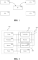
- FIG. 1 illustrates exemplary relationships between an AP and one or more STAs.
- an AP 102 can correspond to a basic equipment in a wireless local area network (WLAN), and STA(s) 104 can establish wireless communications with the AP 102 through a predetermined association or registration procedure, and thereafter communicate with the AP 102 for data transmission.
- the AP 102 together with all associated STAs establish a Basic Service Set (BSS).
- BSS Basic Service Set
- an AP may not be present in the network, and STAs can communicate directly with one another.
- a group of communicatively inter-connected STAs establish an independent BSS (IBSS).
- IBSS independent BSS
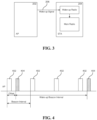
- FIG. 2 illustrates a block diagram of at least a portion of an exemplary STA, in accordance with some embodiments of the presently disclosed technology.
- an exemplary STA e.g., an IoT device
- the main radio 202 can include one or more processors 204, memory 206, transmitter and receiver 208, timing module 210, power module 212, and/or other elements.
- the exemplary STA also includes an assistant wireless module 220, which includes at least a wake-up radio 222 for monitoring wake-up signals from one or more APs.
- the wake-up radio 222 can be configured to perform signal receiving and decoding, information processing and/or relevant function triggering.
- the assistant wireless module 220 can be configured to assist the main radio 202 in the application of certain controlling and managing function(s).
- the exemplary STA can further include one or more sensors 230, one or more antennas 240, and/or other components.
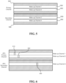
- FIG. 3 shows an example of a typical waking-up process involving an AP 202 and an STA 204.
- the STA 204 initiates a procedure (not shown in FIG. 3 ) to negotiate power-saving mode parameters with its associated AP 202, and then the STA 204 enters a power-saving mode by turning off its main radio and turning on its wake-up radio.
- the STA 204 can be woken up by a wake-up signal 206 transmitted by the AP 202 if any data communication is needed. Similar setup and arrangements can be applied to an AP (not shown in FIG. 3 ).
- an assistant wireless module including least a wake-up radio can be added to an AP.
- the AP can enter a power-saving mode. If an associated STA has data to be transmitted, it can first transmit a wake-up signal for waking up the AP.
- FIG. 4 shows an example of typical Beacon and wake-up Beacon transmission.
- an AP functions as the timing master for any timed functions between the AP and an associated STA.
- the AP transmits Beacon frames 402 periodically.
- Each Beacon frame 402 includes a value of a current timestamp to synchronize the timer(s) of the STA(s) in the BSS. If any STA enters power-saving mode and monitors wake-up signals on a predefined channel, the AP can send another type of frame (e.g., wake-up Beacon 404) carrying timing information on this predefined channel to help the STA in power-saving mode synchronize.
- another type of frame e.g., wake-up Beacon 404
- an AP supporting enhanced wake-up process(es) as disclosed herein can transmit to associated or unassociated STA(s) information that identify, or otherwise facilitate the scanning of, a set of potential serving APs.
- the information can include one or more wake-up parameters sets.
- the AP can use a Beacon frame, Probe Response frame, Association Response frame, and/or certain wake-up frame(s) (e.g., wake-up Beacon) to carry the wake-up parameters set(s), and transmit to one or more STAs.
- the AP can transmit wake-up parameter update sets via one or more of these frames to add, delete, change, or otherwise update any information (e.g., identifiers of potential serving APs) included in previously transmitted wake-up parameters set(s).
- any information e.g., identifiers of potential serving APs
- the wake-up parameters set(s) can include a wake-up parameters set of the transmitting AP.
- the wake-up parameter set(s) can also include wake-up parameters set(s) of other AP(s) such as recommended AP(s), neighboring AP(s), and/or APs within a same virtual BSS group.
- a wake-up parameters set of a particular AP can include the following parameters: location of the wake-up channel(s) of the particular AP, location of the primary channel of the particular AP, identifier(s) (e.g., a distinct BSS color value used to identify the particular AP or a specific Association ID (AID) value used to identify the particular AP) that identify the transmitter of the particular AP's wake-up frames, and/or identifier(s) that identify a virtual BSS group to which the particular AP belongs.
- identifier(s) e.g., a distinct BSS color value used to identify the particular AP or a specific Association ID (AID) value used to identify the particular AP
- AID Association ID
- a wake-up channel is a channel used by an AP to send wake-up frames.
- An AP can determine or be assigned to use one or more wake-up channels.
- the wake-up channel(s) can be predefined in the wireless communication system, determined and informed by the AP, or otherwise provided by the wireless communication system.
- FIG. 5 shows an example of the location of wake-up channels within an AP's primary channel and/or secondary channel(s), in accordance with some embodiments of the presently disclosed technology.
- individual wake-up channels 502 of the AP are located within a corresponding primary channel 504 or secondary channel 506 of the AP, and the bandwidth of a wake-up channel 502 is narrower (or smaller) than that of a corresponding primary channel 504 or secondary channel 506 of the AP.
- the location of wake-up channel(s) is outside of the bandwidth of an AP's primary channel and secondary channel(s).
- an AP's primary channel and secondary channel(s) can all use a 2.4 GHz band while at least one wake-up channel of the AP uses a 5 GHz band.
- the bandwidth of an AP's primary or secondary channel can partially overlap with the bandwidth of at least one wake-up channel of the AP.
- the AP can use different channels to transmit different type of frames. For example, the AP can transmit a Beacon frame, Probe Response frame, and/or Association Response frame via a primary channel or a secondary channel, and transmit a wake-up frame (e.g., a wake-up Beacon) via a wake-up channel.
- a Beacon frame e.g., a Beacon frame
- Probe Response frame e.g., Probe Response frame
- Association Response frame e.g., a wake-up Beacon
- a virtual BSS group corresponds to a set of one or more BSSs that, for example, can a provide a logical or physical contiguous coverage region to one or more STAs.
- the virtual BSS group may be a paging group in which an STA can be woken up by any BSS of the group.
- a virtual BSS group identifier can therefore be an a page group ID.
- the virtual BSS group may include interconnected BSSs that appear as a single BSS to the logical link control (LLC) layer at any STA associated with one of the interconnected BSSs.
- LLC logical link control
- a virtual BSS group can correspond to an extended service set (ESS).
- All the BSSs in a single ESS can be associated with a common service set identifier (SSID).
- ESS can be applied in virtual private networks that are deployed, for example, in various office, plant, warehouse, and/or other applicable scenarios for the ease of STA management.
- Virtual BSS group identifier therefore can be an ESS identifier, such as an ESSID, SSID, compressed ESSID, compressed SSID, or ESS color used to distinguish a particular ESS from other ESS(s).
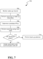
- FIG. 7 is a flowchart of an enhanced process 700 for an STA in power saving mode to wake up, in accordance with some embodiments of the currently disclosed technology.
- an STA in power saving mode monitors a wake-up channel designated by its associated AP for wake-up frames transmitted from its associated AP.
- Wake-up frames can be addressed specifically to the STA, addressed to a group of which the STA is a member, or a broadcast wake-up frame.
- the wake-up frame can take the form of a wake-up signal to wake up the STA, a wake-up signal carrying network selection information, or a wake-up Beacon.
- Information carried by a wake-up frame can include identifier(s) of the transmitter that transmitted the wake-up frame, virtual BSS group identifier(s), wake-up parameters set(s), and/or wake-up parameter update set(s). At least a portion of the information can be placed in an outer, frontal, or otherwise easily-accessible part (e.g., the Physical Layer) of the frame, so that a receiving STA can efficiently filter out the frame if the frame is inapplicable to the receiving STA or if the reception of the frame is not intended.
- an outer, frontal, or otherwise easily-accessible part e.g., the Physical Layer
- the STA starts to perform scanning on one or more wake-up channels.
- the STA starts to perform scanning if one or more predefined conditions are satisfied. For example, the STA maintains a timer to calculate the duration between two successive wake-up frames that include the transmitter address or other identifier(s) of its associated AP. If the STA has not received any wake-up frame with certain identifier(s) of its associated AP for a threshold duration, the STA starts to perform scanning on one or more wake-up channels. In another example, if the RSS of the currently associated AP drops below a threshold, the STA starts to perform scanning on one or more wake-up channels. In some embodiments, when certain predefined conditions are met, instead of or in parallel with the scanning of the wake-up channel(s), the STA turns on its main radio to perform network scanning following scanning procedures known to those skilled in the art.
- the STA performs scanning on one or more wake-up channels in response to its wake-up radio being turned on.
- the STA can scan accessible wake-up channels sequentially, for example, from the lowest center frequency to the highest center frequency (or vice versa).
- the timing and duration that the STA stays on certain wake-up channel(s) can be determined by the associated AP or the STA, or be negotiated between the two.
- the AP has sufficient information for determining when the STA can receive certain wake-up frame on certain wake-up channel(s) designated to the STA, and can send such wake-up frame on demand or in accordance with a schedule.
- the one or more wake-up channels for scanning can be determined from wake-up parameters set(s) and/or wake-up parameter update set(s) included in one or more types of frames received by the STA. Such frame(s) can be sent from the associated AP or any unassociated AP(s).
- the STA scans the wake-up channel(s) located within the primary channel and/or secondary channel(s) of its associated AP. In some embodiments, the STA scans wake-up channel(s) in all accessible primary channel(s) and/or secondary channel(s). In some embodiments, the STA only scans wake-up channel(s) assigned to the STA. In some embodiments, the STA scans wake-up channel(s) located outside of the primary channel and secondary channel(s) assigned to the STA.
- the STA scans a wake-up channel by receiving and decoding wake-up frames using at least the wake-up radio of the STA. Based on the scanning of one or more wake-up channels, the STA obtains information carried by wake-up frames that are received via the one or more wake-up channels.
- the STA determines candidate AP(s) for initiating association and data communication.
- the STA can obtain (1) identifier(s) of transmitter of the received wake-up frame(s), and/or (2) virtual BSS group identifier(s) in the received wake-up frame(s).
- the STA can determine at least a subset of the identifiers in (1) and/or (2) that identify or otherwise indicate one or more APs different from the AP currently associated with the STA.
- the STA can label the subset as candidate AP(s).
- the STA can determine at least a subset of the identifiers in (1) and/or (2) that correspond to the recommended AP(s), neighboring AP(s), or currently unassociated AP(s) in the same virtual BSS group of the STA.
- the STA can label the subset as candidate AP(s).
- the STA can also include any other AP that has been identified as a transmitter of a wake-up frame (e.g., a wake-up Beacon) received during a recent period of time.
- the STA may prefer to choose a candidate AP within the same virtual BSS group of its currently associated AP. For example, in a private network of a warehousing system, many freight companies can use a same warehouse. A plurality of APs of an individual company can form a separate ESS for the ease of management. An STA may prefer to choose a candidate AP within the same ESS of its currently associated AP for convenience and efficiency (e.g., the ESS may support fast BSS transition for the STA).
- the STA turns on its main radio for further scanning.
- the main radio scanning can be passive or/or active.
- the channel(s) to be scanned using the STA's main radio can include the candidate AP(s)' primary channel(s), communication channel(s) whose bandwidth encompasses or otherwise accommodates the candidate AP(s)'s wake-up channel(s), and/or neighboring channel(s) of the same.
- the STA By performing scanning using the main radio, the STA receives Beacons, Probe Response, and/or other frames on each scanned channel. The STA can decode the received frames to obtain AP identifying information (e.g., wake-up parameters set) carried by the frames.
- AP identifying information e.g., wake-up parameters set
- the STA determines whether one or more AP identifiers obtained through main radio scanning match that of the candidate AP(s). For example, in some embodiments, the identifier(s) of transmitter in a wake-up frame transmitted by an AP is also included in a wake-up parameters set carried by a Beacon, Probe Response, and/or other frames transmitted by the same AP. Therefore, once the STA decodes or otherwise obtains the identifier(s) of transmitter in a frame (e.g., Beacon or Probe Response) received via main radio scanning, the STA can compare the obtained identifier(s) of transmitter with one or more of candidate APs' identifier(s) obtained from wake-up frame(s) during wake-up channel scanning.
- a frame e.g., Beacon or Probe Response
- the STA selects a target AP from the matched APs and initiates association (e.g., authentication, parameter exchange, and/or other actions) with the selected target AP.
- association e.g., authentication, parameter exchange, and/or other actions
- the STA can achieve this using a MAC address decoded or otherwise obtained in a Beacon, Probe Response, or other frames transmitted by the target AP.
- the STA selects the target AP based, at least in part, on the capacity, capability, configuration, and/or the RSS of the AP as compared with other matched AP(s).
- the STA can initiate data communication with the target AP via the main radio.
- the STA performs one or more backup actions. For example, the STA can perform wake-up channel scanning using its wake-up radio for another period of time. Alternatively or in addition, the STA can perform a typical, complete scanning on all accessible channels using its main radio based on current scanning procedures known to those skilled in the art.
- FIG. 6 illustrates a use case example, in accordance with some embodiments of the presently disclosed technology.
- 4 APs i.e., AP1, AP2, AP3, and AP4 each sets up an individual BSS.
- the 4 BSS's are grouped into two virtual BSS groups.
- the first virtual BSS group includes AP1 and AP4.
- the second virtual BSS group includes AP2 and AP3.
- different BSS colors can be used to identify different member APs.
- AP4 has a primary channel and a secondary channel, and has three wake-up channels each located in the primary channel or secondary channel, respectively.
- An STA is associated with AP4 and enters power-saving mode.
- AP4 broadcasts wake-up parameters set about itself in one or more Beacon frames.
- AP4 allocates wake-up channel 1 to the STA, so that the STA can monitor, on wake-up channel 1, wake-up frames including wake-up signal, wake-up Beacon, or wake-up signal that carries network selection information.
- the STA When the STA has not received a wake-up Beacon from AP4 for a threshold number of wake-up Beacon intervals, or once the STA enters power-saving mode, the STA starts scanning on wake-up channels.
- the STA can scan wake-up channel 1 and receive AP1's wake-up Beacon 610 that includes AP1's identifier(s) (e.g., a distinct BSS color or other BSS identifier of AP1) and AP1's virtual BSS group ID (e.g., a distinct ESS ID identifying the first virtual BSS group).
- AP1's identifier(s) e.g., a distinct BSS color or other BSS identifier of AP1
- AP1's virtual BSS group ID e.g., a distinct ESS ID identifying the first virtual BSS group.
- the STA can scan all the wake-up channels in a primary channel where the STA's currently designated wake-up channel (i.e., wake-up channel 1) is located. In the example of FIG. 6 , these wake-up channels correspond to wake-up channels 1 and 2 located in AP4's primary channel. By scanning these wake-up channels, the STA can receive AP1's wake-up Beacon 610 and a wake-up signal 620 sent by AP2.
- the wake-up signal 620 can include AP2's identifier(s) and/or AP2's virtual BSS group ID.
- the STA can scan all the wake-up channels of its associated AP (i.e., AP4).
- the STA can scan wake-up channels 1, 2, and 3, and receive AP1's wake-up Beacon 610, AP2's wake-up signal 620, and AP3's wake-up Beacon 630.
- Wake-up Beacon 630 can include AP3's identifier(s) and/or AP3's virtual BSS group ID.
- the STA only scans wake-up channel 1 and wake-up channel 2, the STA can select AP1 in the same virtual BSS group of AP4, as a candidate AP.
- the STA then turns on its main radio to perform scanning on the primary channel and/or secondary channel of AP4 to obtain AP1's Beacon or Probe Response frame. If the location of AP1's primary channel is indicated in AP1's wake-up Beacon 610, the STA performs scanning on AP1's primary channel to obtain AP1's Beacon or Probe Response frame.
- the identifier(s) of transmitter used in wake-up frames transmitted by an AP may be different from those used in non-wake-up frames (e.g., frames transmitted via primary channels) transmitted from the same AP.
- AP1 carries BSS identifier(s) and virtual BSS group identifier(s) in Beacon or Probe Response frames.
- a wake-up element of the Beacon or Probe Response frame is used to contain wake-up parameters set(s), which includes the BSS identifier(s) (e.g., BSS color) and/or virtual BSS group identifier(s) (e.g., ESS ID) used by AP1 in its wake-up frames.
- the STA decodes or otherwise obtains the MAC address contained in the transmitter address field of the received Beacon or Probe Response frame. Then the STA starts association with AP1 using the MAC address, for example, by transmitting authentication request(s) with the MAC address in the receiver address field. If the association is successful, the STA starts data communication with AP1.
- FIGS. 8 and 9 illustrate another use case example, in accordance with some embodiments of the presently disclosed technology.
- 4 APs i.e., AP1, AP2, AP3, and AP4 each sets up an individual BSS 810.
- the 4 BSS's are grouped into two virtual BSS groups.
- the first virtual BSS group 820a includes AP1 and AP2.
- the second virtual BSS group 820b includes AP3 and AP4.
- different BSS colors can be used to identify different member APs.
- AP1 broadcasts wake-up parameters set in its Beacon frame(s). Besides the AP1's wake-up parameters set, AP2's and AP3's wake-up parameters sets are also carried by AP1's Beacon frame(s). In this case, AP2's wake-up parameters set is included because AP2 is within the same virtual BSS group of AP1, and AP3 is a neighboring AP recommended to STAs associated with AP1.
- AP1's wake-up parameters set includes: the location of the wake-up channel used by AP1, the BSS color or other BSS identifier(s) used by AP1 in its wake-up frames, the virtual BSS group identifier(s) of AP1.
- AP2's wake-up parameters set includes: the location of the wake-up channel used by AP2, the BSS color or other BSS identifier(s) used by AP2 in its wake-up frames, the virtual BSS group identifier(s) of AP2, and the location of the primary channel of AP2.
- an STA associated with AP1 can obtain information included in the wake-up parameters set of AP1, AP2, and AP3, respectively.
- AP1 has a wake-up channel 915 located in its primary channel 910.
- An associated STA entering power saving mode monitors the wake-up channel 915 for wake-up frames.
- AP1 can send wake-up parameters set(s) in its wake-up frames.
- AP1 can send a wake-up Beacon 921 carrying wake-up parameters set(s) of AP2 and/or AP3.
- AP1 can send a wake-up signal with network selection information that carries wake-up parameters set(s) of AP1, AP2, and/or AP3. Therefore, the associated STA can obtain corresponding wake-up parameters from wake-up frames received on the wake-up channel 915.
- the STA performs wake-up channel scanning using its wake-up radio.
- the STA can receive AP2's wake-up Beacon 922 on AP2's wake-up channel 915. It can also switch to AP3's wake-up channel 935 and receive AP3's wake-up Beacon 943 and AP4's wake-up Beacon 944.
- the STA can identify and process AP2 and AP3's wake-up Beacon frames.
- the frame identifying process can include, for example, filtering out wake-up frames (e.g., AP4's wake-up Beacon 944) transmitted by other AP(s).
- the STA can label AP2 and AP3 as candidate APs.
- the STA then turns on its main radio to perform scanning using its main radio on AP2's primary channel 910 and AP3's primary channels 930.
- the STA can receive multiple Beacons frames on these primary channels during the scanning.
- the STA can compare the BSS color (or another applicable BSS identifier) included in the wake-up parameter set of the received Beacon frames with one or more candidate AP's BSS color (or another applicable BSS identifier) used in the candidate AP's wake-up frames. Once match(es) is found based on the comparison, the STA processes the matched Beacon(s) and selects a target AP (e.g., AP2 or AP3) based on its capability, capacity, configuration, and/or signal strength. The STA then initiates association and data communication with the target AP.
- a target AP e.g., AP2 or AP3
- the STA can select a target AP based on the wake-up radio scanning.
- the wake-up Beacon frames of AP2 and AP3 that have been received by the STA can indicate signal strength and can include information regarding the transmitting AP's capability, capacity, and/or configuration, which can be processed by the STA for selecting the target AP.
- the STA selects AP2 as the target AP, the STA can turn on its main radio and perform scanning on AP2's primary channel(s).
- the STA may receive multiple Beacons on the primary channel(s) during scanning, and it can compare (a) the BSS color (or another applicable BSS identifier) included in the wake-up parameters set of the received Beacons with (2) AP2's BSS color (or another applicable BSS identifier) used in AP2's wake-up frames. Once a match is found based on the comparison, the STA processes the matched Beacon, and initiates association and data communication with the AP2 based thereon.
- the disclosed and other embodiments, modules and the functional operations described in this document can be implemented in digital electronic circuitry, or in computer software, firmware, or hardware, including the structures disclosed in this document and their structural equivalents, or in combinations of one or more of them.
- the disclosed and other embodiments can be implemented as one or more computer program products, i.e., one or more modules of computer program instructions encoded on a computer readable medium for execution by, or to control the operation of, data processing apparatus.
- the computer readable medium can be a machine-readable storage device, a machine-readable storage substrate, a memory device, a composition of matter effecting a machine-readable propagated signal, or a combination of one or more them.
- data processing apparatus encompasses all apparatus, devices, and machines for processing data, including by way of example a programmable processor, a computer, or multiple processors or computers.
- the apparatus can include, in addition to hardware, code that creates an execution environment for the computer program in question, e.g., code that constitutes processor firmware, a protocol stack, a database management system, an operating system, or a combination of one or more of them.
- a propagated signal is an artificially generated signal, e.g., a machine-generated electrical, optical, or electromagnetic signal, that is generated to encode information for transmission to suitable receiver apparatus.
- a computer program (also known as a program, software, software application, script, or code) can be written in any form of programming language, including compiled or interpreted languages, and it can be deployed in any form, including as a stand alone program or as a module, component, subroutine, or other unit suitable for use in a computing environment.
- a computer program does not necessarily correspond to a file in a file system.
- a program can be stored in a portion of a file that holds other programs or data (e.g., one or more scripts stored in a markup language document), in a single file dedicated to the program in question, or in multiple coordinated files (e.g., files that store one or more modules, sub programs, or portions of code).
- a computer program can be deployed to be executed on one computer or on multiple computers that are located at one site or distributed across multiple sites and interconnected by a communication network.
- the processes and logic flows described in this document can be performed by one or more programmable processors executing one or more computer programs to perform functions by operating on input data and generating output.
- the processes and logic flows can also be performed by, and apparatus can also be implemented as, special purpose logic circuitry, e.g., an FPGA (field programmable gate array) or an ASIC (application specific integrated circuit).
- processors suitable for the execution of a computer program include, by way of example, both general and special purpose microprocessors, and any one or more processors of any kind of digital computer.
- a processor will receive instructions and data from a read only memory or a random access memory or both.
- the essential elements of a computer are a processor for performing instructions and one or more memory devices for storing instructions and data.
- a computer will also include, or be operatively coupled to receive data from or transfer data to, or both, one or more mass storage devices for storing data, e.g., magnetic, magneto optical disks, or optical disks.
- mass storage devices for storing data, e.g., magnetic, magneto optical disks, or optical disks.
- a computer need not have such devices.
- Computer readable media suitable for storing computer program instructions and data include all forms of non-volatile memory, media and memory devices, including by way of example semiconductor memory devices, e.g., EPROM, EEPROM, and flash memory devices; magnetic disks, e.g., internal hard disks or removable disks; magneto optical disks; and CD ROM and DVD-ROM disks.
- semiconductor memory devices e.g., EPROM, EEPROM, and flash memory devices
- magnetic disks e.g., internal hard disks or removable disks
- magneto optical disks e.g., CD ROM and DVD-ROM disks.
- the processor and the memory can be supplemented by, or incorporated in, special purpose logic circuitry.
Claims (13)
- Verfahren zur drahtlosen Kommunikation, das von einer Station (204) im Energiesparmodus durchgeführt wird, wobei das Verfahren aufweist:Empfangen, über einen ersten Kanal, der mit einem ersten Zugangspunkt (202) verbunden ist, mindestens einer ersten Nachricht, die mehrere Sätze von Aufwachparametern enthält,wobei jeder Satz von Aufwachparametern mit einem von mehreren Zugangspunkten verbunden ist, die konfiguriert sind, mit der Station zu kommunizieren,wobei jeder Satz von Aufwachparametern mindestens einen Parameter enthält, der einen Aufwachkanal identifiziert, der mit einem der mehreren Zugangspunkte verbunden ist,wobei die mehreren Zugangspunkte den ersten Zugangspunkt und mindestens einen zweiten Zugangspunkt enthalten;Durchführen eines Scannens an einem oder mehreren Aufwachkanälen, wobei eine Dauer und ein Zeitpunkt, zu dem die Station auf dem einen oder den mehreren Aufwachkanälen bleibt, mit dem ersten Zugangspunkt ausgehandelt wird; undInitiieren einer Kommunikation mit dem zweiten Zugangspunkt basierend auf dem Scannen und über mindestens einen zweiten Kanal, basierend auf der mindestens einen über den ersten Kanal empfangenen ersten Nachricht,wobei der zweite Kanal in einem Satz von Aufwachparametern für den zweiten Zugangspunkt in der mindestens einen ersten Nachricht angezeigt wird.
- Verfahren nach Anspruch 1, das ferner aufweist:
Empfangen, über den zweiten Kanal, mindestens einer zweiten Nachricht, die von dem zweiten Zugangspunkt gesendet wird, wobei die mindestens eine zweite Nachricht mindestens eine Kennung enthält, die den zweiten Zugangspunkt identifiziert. - Verfahren nach Anspruch 2, wobei die mindestens eine Kennung eine komprimierte Dienstsatzkennung, SSID, enthält.
- Verfahren nach Anspruch 1, wobei für jeden Satz von Aufwachparametern der mindestens eine Parameter einen Grunddienstsatzkennung, BSSID, von einem der mehreren Zugangspunkte enthält.
- Verfahren nach Anspruch 1, wobei die mindestens eine erste Nachricht in einem von der Station empfangenen Beaconrahmen oder Sondierungsantwortrahmen enthalten ist.
- Verfahren nach Anspruch 1, wobei der erste Kanal einem Primärkanal entspricht, der mit dem ersten Zugangspunkt verbunden ist.
- Verfahren zur drahtlosen Kommunikation, das von einem ersten Zugangspunkt (202) durchgeführt wird, wobei das Verfahren aufweist:Senden, durch den ersten Zugangspunkt über einen ersten Kanal an eine Station (204), von mindestens einer Nachricht, die mehrere Sätze von Aufwachparametern enthält, wobei jeder Satz von Aufwachparametern mit einem von mehreren Zugangspunkten verbunden ist, die konfiguriert sind, mit der Station zu kommunizieren,wobei jeder Satz von Aufwachparametern mindestens einen Parameter enthält, der einen Aufwachkanal identifiziert, der mit einem der mehreren Zugangspunkte verbunden ist,wobei die mehreren Zugangspunkte den ersten Zugangspunkt und mindestens einen zweiten Zugangspunkt enthalten,wobei ein zweiter Kanal in einem Satz von Aufwachparametern für den zweiten Zugangspunkt in der mindestens einen Nachricht angezeigt wird, undwobei der erste Zugangspunkt mit der Station eine Dauer und einen Zeitpunkt aushandelt, zu dem die Station auf einem oder mehreren Aufwachkanälen bleibt, um eine Abtastung auf dem einen oder den mehreren Aufwachkanälen durchzuführen.
- Verfahren nach Anspruch 7, wobei der erste Kanal einem Primärkanal entspricht, der mit dem ersten Zugangspunkt verbunden ist.
- Verfahren nach Anspruch 7, wobei für jeden Satz von Aufwachparametern der mindestens eine Parameter einen Grunddienstsatzkennung, BSSID, von einem der mehreren Zugangspunkte enthält.
- Verfahren nach Anspruch 7, wobei die mindestens eine Nachricht in einem vom ersten Zugangspunkt gesendeten Beaconrahmen oder Sondierungsantwortrahmen enthalten ist.
- Computervorrichtung, die mit einer Nicht-Zugangspunkt-Station, STA, (204) verbunden ist, wobei die Computervorrichtung einen Prozessor enthält, der konfiguriert ist, die Nicht-Zugangspunkt-STA zu veranlassen, das Verfahren nach einem der Ansprüche 1 bis 6 auszuführen.
- Nichtflüchtiges computerlesbares Medium, auf dem computerausführbare Befehle gespeichert sind, die, wenn sie von einem Computer ausgeführt werden, der mit einer Nicht-Zugangspunkt-Station STA (204) verbunden ist, geeignet sind, das Verfahren nach einem der Ansprüche 1 bis 6 auszuführen, und, wenn sie von einem Computer ausgeführt werden, der mit einem Zugangspunkt AP (202) verbunden ist, geeignet sind, das Verfahren nach einem der Ansprüche 7 bis 10 auszuführen.
- Computervorrichtung, die mit einem Zugangspunkt, AP, (202) verbunden ist, wobei die Computervorrichtung einen Prozessor enthält, der konfiguriert ist, den AP zu veranlassen, das Verfahren nach einem der Ansprüche 7 bis 10 auszuführen.
Applications Claiming Priority (1)
| Application Number | Priority Date | Filing Date | Title |
|---|---|---|---|
| PCT/CN2017/102955 WO2019056307A1 (en) | 2017-09-22 | 2017-09-22 | SCAN AND ASSOCIATION OF WIRELESS COMMUNICATION NODES |
Publications (3)
| Publication Number | Publication Date |
|---|---|
| EP3685609A1 EP3685609A1 (de) | 2020-07-29 |
| EP3685609A4 EP3685609A4 (de) | 2021-02-24 |
| EP3685609B1 true EP3685609B1 (de) | 2023-11-15 |
Family
ID=65810022
Family Applications (1)
| Application Number | Title | Priority Date | Filing Date |
|---|---|---|---|
| EP17925718.3A Active EP3685609B1 (de) | 2017-09-22 | 2017-09-22 | Abtastung und zuordnung von drahtloskommunikationsknoten |
Country Status (6)
| Country | Link |
|---|---|
| US (2) | US11240714B2 (de) |
| EP (1) | EP3685609B1 (de) |
| JP (1) | JP6993501B2 (de) |
| CN (1) | CN111095989B (de) |
| ES (1) | ES2965204T3 (de) |
| WO (1) | WO2019056307A1 (de) |
Family Cites Families (24)
| Publication number | Priority date | Publication date | Assignee | Title |
|---|---|---|---|---|
| US7903620B2 (en) | 2003-07-17 | 2011-03-08 | Interdigital Technology Corporation | Method and system for delivery of assistance data |
| US8934404B2 (en) * | 2008-03-03 | 2015-01-13 | Qualcomm Incorporated | Access point with proxy functionality for facilitating power conservation in wireless client terminals |
| US8311030B2 (en) * | 2008-03-10 | 2012-11-13 | Telefonaktiebolaget Lm Ericsson (Publ) | Enhanced cell scanning |
| CN101483894B (zh) * | 2009-01-06 | 2010-08-11 | 北京交通大学 | 一种无线局域网的快速切换方法 |
| US8811247B2 (en) * | 2010-06-25 | 2014-08-19 | Cisco Technology, Inc. | Automating radio enablement to facilitate power saving |
| US9237496B2 (en) * | 2011-12-05 | 2016-01-12 | Lg Electronics Inc. | Method and apparatus for transmitting channel switching information |
| CN102625427B (zh) * | 2012-03-14 | 2014-07-09 | 东南大学 | 一种基于异步唤醒调度的无线传感器网络数据采集方法 |
| US9596648B2 (en) * | 2012-06-29 | 2017-03-14 | Marvell World Trade Ltd. | Unified beacon format |
| CN104469775B (zh) * | 2012-09-28 | 2018-10-12 | 华为技术有限公司 | 无线局域网接入方法、基站控制器和用户设备 |
| US9241307B2 (en) * | 2012-10-24 | 2016-01-19 | Qualcomm Incorporated | Method and apparatus using an ultra low power signal with scheduled power save modes |
| US9877158B2 (en) * | 2013-12-20 | 2018-01-23 | Intel Corporation | Wi-Fi scan scheduling and power adaptation for low-power indoor location |
| US9420503B2 (en) * | 2014-01-21 | 2016-08-16 | Cisco Technology, Inc. | System and method for seamless mobility in a network environment |
| US9877272B2 (en) * | 2014-03-25 | 2018-01-23 | Qualcomm, Incorporated | Initial scan enhancements |
| US9955333B2 (en) * | 2014-08-20 | 2018-04-24 | Qualcomm, Incorporated | Secure wireless wake-up companion |
| CN104602324B (zh) * | 2015-01-27 | 2018-09-11 | 广东欧珀移动通信有限公司 | 无线接入点的扫描方法、扫描装置和终端设备 |
| CN107431927A (zh) * | 2015-03-30 | 2017-12-01 | 高通股份有限公司 | 安全无线唤醒伴随 |
| US9826483B2 (en) * | 2015-06-22 | 2017-11-21 | Intel Corporation | Apparatus, system and method of communicating a wakeup packet |
| US10681606B2 (en) * | 2015-12-17 | 2020-06-09 | Intel Corporation | Fast moving scenario access point switching |
| US20180103430A1 (en) * | 2016-10-10 | 2018-04-12 | Qualcomm Incorporated | Access point discovery using a wakeup receiver |
| US20180184435A1 (en) * | 2016-12-27 | 2018-06-28 | Intel IP Corporation | Apparatus, system, and method for transitioning between wireless access points based on a received signal strength indicator value of a low-power wake-up packet |
| CN109151959B (zh) * | 2017-06-28 | 2021-02-12 | 华为技术有限公司 | 无线通信方法和无线通信设备 |
| US11259244B2 (en) * | 2017-08-17 | 2022-02-22 | Lg Electronics Inc. | Method for transmitting or receiving frame in wireless LAN and device therefor |
| CN109429314A (zh) * | 2017-08-25 | 2019-03-05 | 华为技术有限公司 | 无线网络中wur终端的唤醒方法及装置 |
| EP3677073A4 (de) * | 2017-08-30 | 2020-09-30 | Panasonic Intellectual Property Corporation of America | Kommunikationsvorrichtung und kommunikationsverfahren |
-
2017
- 2017-09-22 CN CN201780095032.6A patent/CN111095989B/zh active Active
- 2017-09-22 EP EP17925718.3A patent/EP3685609B1/de active Active
- 2017-09-22 ES ES17925718T patent/ES2965204T3/es active Active
- 2017-09-22 WO PCT/CN2017/102955 patent/WO2019056307A1/en unknown
- 2017-09-22 JP JP2020516523A patent/JP6993501B2/ja active Active
-
2020
- 2020-03-20 US US16/826,143 patent/US11240714B2/en active Active
-
2022
- 2022-01-04 US US17/568,206 patent/US20220132378A1/en active Pending
Also Published As
| Publication number | Publication date |
|---|---|
| US11240714B2 (en) | 2022-02-01 |
| JP6993501B2 (ja) | 2022-01-13 |
| ES2965204T3 (es) | 2024-04-11 |
| WO2019056307A1 (en) | 2019-03-28 |
| EP3685609A4 (de) | 2021-02-24 |
| US20200260343A1 (en) | 2020-08-13 |
| EP3685609A1 (de) | 2020-07-29 |
| CN111095989A (zh) | 2020-05-01 |
| JP2020534756A (ja) | 2020-11-26 |
| US20220132378A1 (en) | 2022-04-28 |
| CN111095989B (zh) | 2021-10-15 |
Similar Documents
| Publication | Publication Date | Title |
|---|---|---|
| US11252667B2 (en) | Control information transmission method and apparatus | |
| US9635613B2 (en) | Method and apparatus using an ultra low power signal with scheduled power save modes | |
| CN108738109B (zh) | 一种站点唤醒方法及站点 | |
| US8995407B2 (en) | Neighbor discovery in a wireless system | |
| US9439139B2 (en) | Method and apparatus for controlling operation state of base station in wireless communication system | |
| CN107743718B (zh) | 经由nan代理服务器提供代理服务的方法和装置 | |
| US9439147B2 (en) | Mechanisms of reducing power consumption for NAN devices | |
| EP3331275B1 (de) | Verfahren zur benachrichtigung einer kanalübergabe von einem mobilfunknetz unterstützt | |
| CN107889199B (zh) | 一种状态转换方法及装置 | |
| US20190364503A1 (en) | Power-save mode for wireless device | |
| US20160066270A1 (en) | Multi-modal wireless connection management | |
| CN108462985B (zh) | 一种通信模式切换方法及装置 | |
| US20110299426A1 (en) | Starting a Wireless Communications Network using wireless signal | |
| JP2011049844A (ja) | 無線装置、無線装置の動作モード切換え方法 | |
| US8112085B2 (en) | Anchor selection in distributed networks | |
| WO2017143989A1 (zh) | 一种信号传输方法、终端及网络侧设备 | |
| US11240714B2 (en) | Wireless communication node scanning and association | |
| JP7252304B2 (ja) | 無線通信ノードのスキャニングおよびアソシエーション | |
| WO2018162791A1 (en) | Protected wake-up of dozing wireless device |
Legal Events
| Date | Code | Title | Description |
|---|---|---|---|
| STAA | Information on the status of an ep patent application or granted ep patent |
Free format text: STATUS: THE INTERNATIONAL PUBLICATION HAS BEEN MADE |
|
| PUAI | Public reference made under article 153(3) epc to a published international application that has entered the european phase |
Free format text: ORIGINAL CODE: 0009012 |
|
| STAA | Information on the status of an ep patent application or granted ep patent |
Free format text: STATUS: REQUEST FOR EXAMINATION WAS MADE |
|
| 17P | Request for examination filed |
Effective date: 20200420 |
|
| AK | Designated contracting states |
Kind code of ref document: A1 Designated state(s): AL AT BE BG CH CY CZ DE DK EE ES FI FR GB GR HR HU IE IS IT LI LT LU LV MC MK MT NL NO PL PT RO RS SE SI SK SM TR |
|
| AX | Request for extension of the european patent |
Extension state: BA ME |
|
| DAV | Request for validation of the european patent (deleted) | ||
| DAX | Request for extension of the european patent (deleted) | ||
| A4 | Supplementary search report drawn up and despatched |
Effective date: 20210125 |
|
| RIC1 | Information provided on ipc code assigned before grant |
Ipc: H04W 36/30 20090101ALN20210119BHEP Ipc: H04W 36/00 20090101ALI20210119BHEP Ipc: H04W 84/12 20090101ALN20210119BHEP Ipc: H04W 52/02 20090101AFI20210119BHEP Ipc: H04W 36/08 20090101ALI20210119BHEP |
|
| STAA | Information on the status of an ep patent application or granted ep patent |
Free format text: STATUS: EXAMINATION IS IN PROGRESS |
|
| 17Q | First examination report despatched |
Effective date: 20230207 |
|
| RIC1 | Information provided on ipc code assigned before grant |
Ipc: H04W 84/12 20090101ALN20230421BHEP Ipc: H04W 36/30 20090101ALN20230421BHEP Ipc: H04W 36/00 20090101ALI20230421BHEP Ipc: H04W 36/08 20090101ALI20230421BHEP Ipc: H04W 52/02 20090101AFI20230421BHEP |
|
| GRAP | Despatch of communication of intention to grant a patent |
Free format text: ORIGINAL CODE: EPIDOSNIGR1 |
|
| STAA | Information on the status of an ep patent application or granted ep patent |
Free format text: STATUS: GRANT OF PATENT IS INTENDED |
|
| RIC1 | Information provided on ipc code assigned before grant |
Ipc: H04W 84/12 20090101ALN20230502BHEP Ipc: H04W 36/30 20090101ALN20230502BHEP Ipc: H04W 36/00 20090101ALI20230502BHEP Ipc: H04W 36/08 20090101ALI20230502BHEP Ipc: H04W 52/02 20090101AFI20230502BHEP |
|
| INTG | Intention to grant announced |
Effective date: 20230606 |
|
| GRAS | Grant fee paid |
Free format text: ORIGINAL CODE: EPIDOSNIGR3 |
|
| GRAA | (expected) grant |
Free format text: ORIGINAL CODE: 0009210 |
|
| STAA | Information on the status of an ep patent application or granted ep patent |
Free format text: STATUS: THE PATENT HAS BEEN GRANTED |
|
| AK | Designated contracting states |
Kind code of ref document: B1 Designated state(s): AL AT BE BG CH CY CZ DE DK EE ES FI FR GB GR HR HU IE IS IT LI LT LU LV MC MK MT NL NO PL PT RO RS SE SI SK SM TR |
|
| REG | Reference to a national code |
Ref country code: CH Ref legal event code: EP Ref country code: GB Ref legal event code: FG4D |
|
| REG | Reference to a national code |
Ref country code: DE Ref legal event code: R096 Ref document number: 602017076649 Country of ref document: DE |
|
| REG | Reference to a national code |
Ref country code: IE Ref legal event code: FG4D |
|
| REG | Reference to a national code |
Ref country code: NL Ref legal event code: FP |
|
| REG | Reference to a national code |
Ref country code: SE Ref legal event code: TRGR |
|
| REG | Reference to a national code |
Ref country code: LT Ref legal event code: MG9D |
|
| PG25 | Lapsed in a contracting state [announced via postgrant information from national office to epo] |
Ref country code: GR Free format text: LAPSE BECAUSE OF FAILURE TO SUBMIT A TRANSLATION OF THE DESCRIPTION OR TO PAY THE FEE WITHIN THE PRESCRIBED TIME-LIMIT Effective date: 20240216 |
|
| PG25 | Lapsed in a contracting state [announced via postgrant information from national office to epo] |
Ref country code: IS Free format text: LAPSE BECAUSE OF FAILURE TO SUBMIT A TRANSLATION OF THE DESCRIPTION OR TO PAY THE FEE WITHIN THE PRESCRIBED TIME-LIMIT Effective date: 20240315 |
|
| REG | Reference to a national code |
Ref country code: ES Ref legal event code: FG2A Ref document number: 2965204 Country of ref document: ES Kind code of ref document: T3 Effective date: 20240411 |
|
| PG25 | Lapsed in a contracting state [announced via postgrant information from national office to epo] |
Ref country code: LT Free format text: LAPSE BECAUSE OF FAILURE TO SUBMIT A TRANSLATION OF THE DESCRIPTION OR TO PAY THE FEE WITHIN THE PRESCRIBED TIME-LIMIT Effective date: 20231115 |
|
| REG | Reference to a national code |
Ref country code: AT Ref legal event code: MK05 Ref document number: 1632915 Country of ref document: AT Kind code of ref document: T Effective date: 20231115 |
|
| PG25 | Lapsed in a contracting state [announced via postgrant information from national office to epo] |
Ref country code: AT Free format text: LAPSE BECAUSE OF FAILURE TO SUBMIT A TRANSLATION OF THE DESCRIPTION OR TO PAY THE FEE WITHIN THE PRESCRIBED TIME-LIMIT Effective date: 20231115 |
|
| PG25 | Lapsed in a contracting state [announced via postgrant information from national office to epo] |
Ref country code: LT Free format text: LAPSE BECAUSE OF FAILURE TO SUBMIT A TRANSLATION OF THE DESCRIPTION OR TO PAY THE FEE WITHIN THE PRESCRIBED TIME-LIMIT Effective date: 20231115 Ref country code: IS Free format text: LAPSE BECAUSE OF FAILURE TO SUBMIT A TRANSLATION OF THE DESCRIPTION OR TO PAY THE FEE WITHIN THE PRESCRIBED TIME-LIMIT Effective date: 20240315 Ref country code: GR Free format text: LAPSE BECAUSE OF FAILURE TO SUBMIT A TRANSLATION OF THE DESCRIPTION OR TO PAY THE FEE WITHIN THE PRESCRIBED TIME-LIMIT Effective date: 20240216 Ref country code: BG Free format text: LAPSE BECAUSE OF FAILURE TO SUBMIT A TRANSLATION OF THE DESCRIPTION OR TO PAY THE FEE WITHIN THE PRESCRIBED TIME-LIMIT Effective date: 20240215 Ref country code: AT Free format text: LAPSE BECAUSE OF FAILURE TO SUBMIT A TRANSLATION OF THE DESCRIPTION OR TO PAY THE FEE WITHIN THE PRESCRIBED TIME-LIMIT Effective date: 20231115 Ref country code: PT Free format text: LAPSE BECAUSE OF FAILURE TO SUBMIT A TRANSLATION OF THE DESCRIPTION OR TO PAY THE FEE WITHIN THE PRESCRIBED TIME-LIMIT Effective date: 20240315 |