EP3685498B1 - Geometry of magnetic bridges of an electrical machine rotor - Google Patents
Geometry of magnetic bridges of an electrical machine rotor Download PDFInfo
- Publication number
- EP3685498B1 EP3685498B1 EP18762824.3A EP18762824A EP3685498B1 EP 3685498 B1 EP3685498 B1 EP 3685498B1 EP 18762824 A EP18762824 A EP 18762824A EP 3685498 B1 EP3685498 B1 EP 3685498B1
- Authority
- EP
- European Patent Office
- Prior art keywords
- rotor
- stator
- electric machine
- flux barrier
- barrier
- Prior art date
- Legal status (The legal status is an assumption and is not a legal conclusion. Google has not performed a legal analysis and makes no representation as to the accuracy of the status listed.)
- Active
Links
- 230000005291 magnetic effect Effects 0.000 title claims description 42
- 230000004907 flux Effects 0.000 claims description 51
- 230000004888 barrier function Effects 0.000 claims description 48
- 230000005534 acoustic noise Effects 0.000 description 3
- 239000007787 solid Substances 0.000 description 3
- 230000001360 synchronised effect Effects 0.000 description 3
- 238000010586 diagram Methods 0.000 description 2
- 238000004804 winding Methods 0.000 description 2
- 208000031968 Cadaver Diseases 0.000 description 1
- 230000000052 comparative effect Effects 0.000 description 1
- 230000036461 convulsion Effects 0.000 description 1
- 230000005294 ferromagnetic effect Effects 0.000 description 1
- 239000003302 ferromagnetic material Substances 0.000 description 1
- 238000001228 spectrum Methods 0.000 description 1
Images

Classifications
-
- H—ELECTRICITY
- H02—GENERATION; CONVERSION OR DISTRIBUTION OF ELECTRIC POWER
- H02K—DYNAMO-ELECTRIC MACHINES
- H02K1/00—Details of the magnetic circuit
- H02K1/06—Details of the magnetic circuit characterised by the shape, form or construction
- H02K1/22—Rotating parts of the magnetic circuit
- H02K1/27—Rotor cores with permanent magnets
- H02K1/2706—Inner rotors
- H02K1/272—Inner rotors the magnetisation axis of the magnets being perpendicular to the rotor axis
- H02K1/274—Inner rotors the magnetisation axis of the magnets being perpendicular to the rotor axis the rotor consisting of two or more circumferentially positioned magnets
- H02K1/2753—Inner rotors the magnetisation axis of the magnets being perpendicular to the rotor axis the rotor consisting of two or more circumferentially positioned magnets the rotor consisting of magnets or groups of magnets arranged with alternating polarity
- H02K1/276—Magnets embedded in the magnetic core, e.g. interior permanent magnets [IPM]
-
- H—ELECTRICITY
- H02—GENERATION; CONVERSION OR DISTRIBUTION OF ELECTRIC POWER
- H02K—DYNAMO-ELECTRIC MACHINES
- H02K21/00—Synchronous motors having permanent magnets; Synchronous generators having permanent magnets
- H02K21/12—Synchronous motors having permanent magnets; Synchronous generators having permanent magnets with stationary armatures and rotating magnets
- H02K21/14—Synchronous motors having permanent magnets; Synchronous generators having permanent magnets with stationary armatures and rotating magnets with magnets rotating within the armatures
-
- H—ELECTRICITY
- H02—GENERATION; CONVERSION OR DISTRIBUTION OF ELECTRIC POWER
- H02K—DYNAMO-ELECTRIC MACHINES
- H02K29/00—Motors or generators having non-mechanical commutating devices, e.g. discharge tubes or semiconductor devices
- H02K29/03—Motors or generators having non-mechanical commutating devices, e.g. discharge tubes or semiconductor devices with a magnetic circuit specially adapted for avoiding torque ripples or self-starting problems
-
- H—ELECTRICITY
- H02—GENERATION; CONVERSION OR DISTRIBUTION OF ELECTRIC POWER
- H02K—DYNAMO-ELECTRIC MACHINES
- H02K1/00—Details of the magnetic circuit
- H02K1/06—Details of the magnetic circuit characterised by the shape, form or construction
- H02K1/22—Rotating parts of the magnetic circuit
- H02K1/24—Rotor cores with salient poles ; Variable reluctance rotors
- H02K1/246—Variable reluctance rotors
-
- H—ELECTRICITY
- H02—GENERATION; CONVERSION OR DISTRIBUTION OF ELECTRIC POWER
- H02K—DYNAMO-ELECTRIC MACHINES
- H02K1/00—Details of the magnetic circuit
- H02K1/06—Details of the magnetic circuit characterised by the shape, form or construction
- H02K1/22—Rotating parts of the magnetic circuit
- H02K1/27—Rotor cores with permanent magnets
- H02K1/2706—Inner rotors
- H02K1/272—Inner rotors the magnetisation axis of the magnets being perpendicular to the rotor axis
- H02K1/274—Inner rotors the magnetisation axis of the magnets being perpendicular to the rotor axis the rotor consisting of two or more circumferentially positioned magnets
- H02K1/2753—Inner rotors the magnetisation axis of the magnets being perpendicular to the rotor axis the rotor consisting of two or more circumferentially positioned magnets the rotor consisting of magnets or groups of magnets arranged with alternating polarity
- H02K1/276—Magnets embedded in the magnetic core, e.g. interior permanent magnets [IPM]
- H02K1/2766—Magnets embedded in the magnetic core, e.g. interior permanent magnets [IPM] having a flux concentration effect
-
- H—ELECTRICITY
- H02—GENERATION; CONVERSION OR DISTRIBUTION OF ELECTRIC POWER
- H02K—DYNAMO-ELECTRIC MACHINES
- H02K2213/00—Specific aspects, not otherwise provided for and not covered by codes H02K2201/00 - H02K2211/00
- H02K2213/03—Machines characterised by numerical values, ranges, mathematical expressions or similar information
Definitions
- the present invention relates to a rotating synchronous electrical machine with variable reluctance assisted by permanent magnets and more particularly to a rotor of such a machine which operates with a high voltage DC bus which allows high power.
- such an electric machine comprises a stator and a rotor arranged coaxially one inside the other.
- the rotor is formed by a rotor body with a stack of sheets placed on a rotor shaft. These sheets include housings for permanent magnets and perforations to create flux barriers making it possible to direct the magnetic flux from the magnets radially towards the stator and to promote the creation of a reluctant couple.
- This rotor is generally housed inside a stator which carries electrical windings making it possible to generate a magnetic field making it possible to drive the rotor in rotation.
- the rotor comprises a plurality of axial recesses which pass right through the sheets.
- a first series of axial recesses arranged radially one above the other and at a distance from one another, form housings for magnetic flux generators, here permanent magnets in the form of a rectangular bar.
- the other series of recesses consists of perforations in an inclined radial direction, which start from these housings to arrive in the vicinity of the edge of the sheets.
- the inclined perforations are arranged symmetrically with respect to the housings of the magnets so as to form each time a substantially V-shaped geometric figure with a flattened bottom with the flat bottom formed by the housing of the magnets and with the inclined arms of this V formed by perforations. This creates flow barriers formed by the perforations.
- the magnetic flux coming from the magnets can then only pass through the solid parts between the perforations. These solid parts are made of a ferromagnetic material.
- the document WO2016198468 describes an electric drive motor for a vehicle.
- the electric drive motor has a stator having a plurality of slots, and a rotor having a plurality of poles.
- the poles each have at least a first permanent magnet centered on an axis of the pole and a plurality of flow barriers for interrupting at minus an n-order torque harmonic of the electric drive motor.
- the present invention aims to remedy the drawbacks listed above and in particular to reduce torque ripple, counter-electromotive force harmonics and acoustic noise.
- the invention also relates to an electrical machine which comprises a stator and a rotor as described above and in which the rotor is housed inside said rotor. stator.
- the stator comprises a multiplicity of radial notches disposed circumferentially along said stator.
- the notches extend axially along the stator.
- the stator has an outer diameter of between 100 and 300 mm and is preferably 200 mm and has an inner diameter of between 100 and 200 mm and is preferably 135 mm.
- the electrical machine comprises an air gap whose length is between 0.4 mm and 0.8 mm and is preferably equal to 0.6 mm.
- a rotor 1 comprises, in a manner known per se, a shaft 2, preferably magnetic, on which is placed a stack of sheets 3.
- these sheets 3 are flat ferromagnetic, identical, rolled and circular in shape and are assembled to each other by any known means.
- the sheets 3 comprise a central bore 4 through which the rotor shaft 2 passes and a plurality of axial recesses 5 which pass through the sheets 3 right through.
- the axial recesses 6 form trapezoids.
- the axial recesses 6 can take other shapes, in particular rectangular or square shapes.
- the other series of recesses consists of perforations of inclined radial direction 8, which start from the axial recesses 6 to arrive in the vicinity of the edge of the sheets 3, that is to say at an air gap of the electrical machine. .
- the rotor 1 comprises eight magnetic poles as visible at the figure 2 .
- Each magnetic pole is composed of three permanent magnets 7 positioned in the three axial recesses 6 provided to house the permanent magnets 7.
- the rotor 1 is also composed of three flux barriers including an external flux barrier 9, a middle flux barrier 10 and an internal flow barrier 11.
- each flux barrier (9, 10, 11) comprises two inclined perforations which are arranged symmetrically with respect to the housings of the magnets 7 for each magnetic pole.
- For each flux barrier (9, 10, 11) of each magnetic pole will correspond an opening angle ( ⁇ 1, ⁇ 2, ⁇ 3) which will qualify the opening of the V-shape.
- opening angles correspond to l the angle between two straight lines ( ⁇ 1, ⁇ 2) each passing through a center C of the rotor 1 and through a midpoint M positioned at an external face 12 of the perforations of inclined radial direction 8 of each flow barrier.
- This outer face 12 is located at a mechanical air gap of the machine, as will be seen below.
- the rotor 1 comprises two architectures of magnetic poles. For this purpose, it comprises four primary magnetic poles 13 and four secondary magnetic poles 14.
- the primary magnetic poles 13 are each composed of an external flux barrier 9 which comprises an opening angle ⁇ 1 substantially equal to 43.1 °, of a central flux barrier 10 comprising an angle of opening ⁇ 2 substantially equal to 33.1 ° and an internal flow barrier 11 comprising an opening angle ⁇ 3 substantially equal to 23.1 °.
- the four secondary magnetic poles 14 are each composed of an external flux barrier 9 comprising an opening angle ⁇ 1 substantially equal to 34.4 °, of a central flux barrier 10 comprising an opening angle ⁇ 2 substantially equal to 24.4 ° and an internal flow barrier 11 comprising an opening angle ⁇ 3 substantially equal to 14.4 °.
- the term “substantially equal” for the angles is understood to mean the fact that the latter may vary by one or two degrees but are preferably given by the values mentioned above.
- a major aspect of the invention is that the rotor 1 comprises an alternation between the primary magnetic poles 13 and the secondary magnetic poles 14. In this way the ripple of the torque, the counter-electromotive force harmonics and the acoustic noise are strongly reduced compared to the electric machine of the prior art.
- the difference between the opening angles for each Specific flux barrier is constant for each pair of alternating primary and secondary poles. This angular difference is substantially equal to 8.7 °. This angular difference of 8.7 ° is found for the external, central and internal flow barriers for each primary 13 and secondary 14 pole which follow one another.
- the angular difference between the opening angles ⁇ 1 of the external flux barriers 9 of a primary magnetic pole 13 and of a secondary magnetic pole 14 is equal to 43.1 ° minus 34.4 ° or 8.7 °. The same goes for the opening angles of the other flow barriers.
- Asymmetric flow barriers are thus created between two consecutive poles.
- the magnetic flux coming from the magnets can then only pass through the solid parts between the perforations and makes it possible to reduce the torque ripple, the counter-electromotive force harmonics and the acoustic noise.
- the rotor 1 has a length of 150 mm, and the sheets 3 constituting the rotor 1 are rolled to 0.35 mm.
- these values are in no way limiting and it is possible to have all the distance spectra which satisfy the angle values stated above.
- the electrical machine also comprises a stator 15 nested in the rotor 1 in a coaxial manner.
- the stator 15 comprises an annular ring 16 with an internal wall 17, the internal diameter of which is designed to receive the rotor 1 with a space necessary to produce an air gap 18.
- This ring comprises a multiplicity of holes, here of oblong section, which form holes. notches 19 for the armature windings.
- these bores extend axially all along the stator, being disposed radially on the ring while being placed circumferentially at a distance from each other by a distance D.
- the stator has an outside diameter of 200 mm and an inside diameter of 135 mm.
- the length of the air gap 18 of the electrical machine is 0.6 mm.
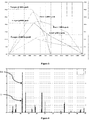
- the figure 3 represents the electromagnetic performance of the electric machine in an application where the DC bus voltage (discontinuous current) is 350 V, the continuous point is at a peak of 400 A, the "peak” point is at a value of 600 A and the maximum speed is 16,800 rpm (14,000 rpm + 20% overspeed).
- the speed of the electric machine is shown in revolutions per minute and on the ordinate the torque in Nm for continuous curves and power in kW (scale on the right) for dotted curves.
- the figure 4 which is a comparative diagram between an electric machine of the prior art (AA) described in the document WO2016188764 and an electric machine according to the invention (I), illustrates the differences in amplitude of the harmonics with respect to the fundamental and confirms the expected result which is the reduction of the ripples of the torque and of the counter-electromotive force harmonics due to the alternation of the primary 13 and secondary magnetic poles 14.
- the diagram represents on the abscissa the electrical order of the harmonics and on the ordinate the back electromotive force in the case of the two electric machines (AA and 1).
- the following table shows the torque ripples in the right column and thus summarizes the gains obtained thanks to the new architecture of the invention for values of 210, 260 and 302 Nm: 400 A- - 210 Nm (0.53 Nm / A) prior art electric machine 9.8% electric machine according to the invention 8.8% 500 A- - 260 Nm (0.52 Nm / A) prior art electric machine 15.0% electric machine according to the invention 8.9% 600 A- - 302 Nm (0.50 Nm / A) prior art electric machine 18.7% electric machine according to the invention 8.6%
Description
La présente invention se rapporte à une machine électrique tournante synchrone à réluctance variable assistée d'aimants permanents et plus particulièrement à un rotor d'une telle machine qui fonctionne avec un bus continu haute tension qui permet une forte puissance.The present invention relates to a rotating synchronous electrical machine with variable reluctance assisted by permanent magnets and more particularly to a rotor of such a machine which operates with a high voltage DC bus which allows high power.
Généralement, une telle machine électrique comporte un stator et un rotor disposés coaxialement l'un dans l'autre.Generally, such an electric machine comprises a stator and a rotor arranged coaxially one inside the other.
Le rotor est formé d'un corps de rotor avec un empilage de tôles placé sur un arbre de rotor. Ces tôles comprennent des logements pour des aimants permanents et des perforations pour créer des barrières de flux permettant de diriger radialement le flux magnétique des aimants vers le stator et pour favoriser la création d'un couple reluctant.The rotor is formed by a rotor body with a stack of sheets placed on a rotor shaft. These sheets include housings for permanent magnets and perforations to create flux barriers making it possible to direct the magnetic flux from the magnets radially towards the stator and to promote the creation of a reluctant couple.
Ce rotor est généralement logé à l'intérieur d'un stator qui porte des bobinages électriques permettant de générer un champ magnétique permettant d'entraîner en rotation le rotor.This rotor is generally housed inside a stator which carries electrical windings making it possible to generate a magnetic field making it possible to drive the rotor in rotation.
Comme cela est mieux décrit dans le document
Une première série d'évidements axiaux, disposés radialement les uns au-dessus des autres et à distance les uns des autres, forment des logements pour des générateurs de flux magnétiques, ici des aimants permanents sous forme de barreau rectangulaire.A first series of axial recesses, arranged radially one above the other and at a distance from one another, form housings for magnetic flux generators, here permanent magnets in the form of a rectangular bar.
L'autre série d'évidements consiste en des perforations de direction radiale inclinée, qui partent de ces logements pour arriver au voisinage du bord des tôles.The other series of recesses consists of perforations in an inclined radial direction, which start from these housings to arrive in the vicinity of the edge of the sheets.
Les perforations inclinées sont disposées symétriquement par rapport aux logements des aimants de manière à former à chaque fois une figure géométrique sensiblement en forme de V à fond aplati avec le fond plat formé par le logement des aimants et avec les bras inclinés de ce V formés par les perforations. Il se crée ainsi des barrières de flux formées par les perforations. Le flux magnétique provenant des aimants ne peut alors que transiter par les parties pleines entre les perforations. Ces parties pleines sont constituées d'un matériau ferromagnétique.The inclined perforations are arranged symmetrically with respect to the housings of the magnets so as to form each time a substantially V-shaped geometric figure with a flattened bottom with the flat bottom formed by the housing of the magnets and with the inclined arms of this V formed by perforations. This creates flow barriers formed by the perforations. The magnetic flux coming from the magnets can then only pass through the solid parts between the perforations. These solid parts are made of a ferromagnetic material.
Le document
Cependant il a été constaté que les harmoniques de force contre-électromotrice et l'ondulation du couple sont importantes dans ce type de machine synchrone à réluctance assistée d'aimants permanents.However, it has been observed that the counter-electromotive force harmonics and the torque ripple are important in this type of synchronous reluctance machine assisted by permanent magnets.
Ceci peut générer des à-coups et des vibrations au niveau du rotor en entraînant un inconfort d'utilisation de cette machine. La présente invention vise à remédier aux inconvénients énumérés ci-dessus et notamment à réduire l'ondulation du couple, les harmoniques de force contre-électromotrice et le bruit acoustique.This can generate jerks and vibrations at the rotor level, causing discomfort in the use of this machine. The present invention aims to remedy the drawbacks listed above and in particular to reduce torque ripple, counter-electromotive force harmonics and acoustic noise.
Ainsi, pour atteindre au moins l'un des objectifs susvisés, parmi d'autres, la présente invention propose, selon un premier aspect, un rotor pour machine électrique, le rotor comprend :
- un corps de rotor, formé par un empilage de tôles, placé sur un arbre de rotor et
- huit pôles magnétiques, chaque pôle magnétique est composé d'au moins trois aimants positionnés dans des évidements axiaux et
- trois barrières de flux asymétriques qui composent chaque pôle magnétique dont une barrière de flux externe, une barrière de flux centrale et une barrière de flux interne, chaque barrière de flux comprend deux évidements inclinés, positionnés de part et d'autre de chaque évidement axial, qui forment entre eux un angle d'ouverture (θ1, θ2, θ3) qui correspond à l'angle entre deux droites passant chacune par le centre du rotor et par un point milieu positionné au niveau d'une face radialement externe des évidements inclinés respectifs de chaque barrière de flux
caractérisé en ce que les huit pôles magnétiques sont divisés en quatre pôles magnétiques primaires et quatre pôles magnétiques secondaires et - les quatre pôles magnétiques primaires sont composés chacun d'une barrière de flux externe comprenant un angle d'ouverture θ1 sensiblement égal à 43,1°, d'une barrière de flux centrale comprenant un angle d'ouverture θ2 sensiblement égal à 33,1° et une barrière de flux interne comprenant un angle d'ouverture θ3 sensiblement égal à 23,1° et
- les quatre pôles magnétiques secondaires sont composés chacun d'une barrière de flux externe comprenant un angle d'ouverture θ1 sensiblement égal à 34,4°, d'une barrière de flux centrale comprenant un angle d'ouverture θ2 sensiblement égal à 24,4° et une barrière de flux interne comprenant un angle d'ouverture θ3 sensiblement égal à 14,4° et
- chaque pôle secondaire est alterné avec un pôle primaire et
- une différence entre les angles d'ouverture de chaque barrière de flux respective d'un pôle magnétique primaire à un pôle magnétique secondaire est égale à 8,7°.
- a rotor body, formed by a stack of sheets, placed on a rotor shaft and
- eight magnetic poles, each magnetic pole is composed of at least three magnets positioned in axial recesses and
- three asymmetric flux barriers which make up each magnetic pole including an external flux barrier, a central flux barrier and an internal flux barrier, each flux barrier comprises two inclined recesses, positioned on either side of each axial recess, which form between them an opening angle (θ1, θ2, θ3) which corresponds to the angle between two straight lines each passing through the center of the rotor and through a midpoint positioned at a radially outer face of the respective inclined recesses of each flow barrier
characterized in that the eight magnetic poles are divided into four primary magnetic poles and four secondary magnetic poles and - the four primary magnetic poles are each composed of an external flux barrier comprising an opening angle θ1 substantially equal to 43.1 °, of a central flux barrier comprising an opening angle θ2 substantially equal to 33.1 ° and an internal flow barrier comprising an opening angle θ3 substantially equal to 23.1 ° and
- the four secondary magnetic poles are each composed of an external flux barrier comprising an opening angle θ1 substantially equal to 34.4 °, of a central flux barrier comprising an opening angle θ2 substantially equal to 24.4 ° and an internal flow barrier comprising an opening angle θ3 substantially equal to 14.4 ° and
- each secondary pole is alternated with a primary pole and
- a difference between the opening angles of each respective flux barrier from a primary magnetic pole to a secondary magnetic pole is equal to 8.7 °.
L'invention concerne également une machine électrique qui comprend un stator et un rotor tel que décrit précédemment et dans laquelle le rotor est logé à l'intérieur dudit stator.The invention also relates to an electrical machine which comprises a stator and a rotor as described above and in which the rotor is housed inside said rotor. stator.
Selon un mode de réalisation de l'invention, le stator comprend une multiplicité d'encoches radiales disposées circonférentiellement le long dudit stator.According to one embodiment of the invention, the stator comprises a multiplicity of radial notches disposed circumferentially along said stator.
Selon un mode de réalisation de l'invention, les encoches s'étendent axialement le long du stator.According to one embodiment of the invention, the notches extend axially along the stator.
Selon un mode de réalisation de l'invention, le stator a un diamètre extérieur compris entre 100 et 300 mm et est de préférence de 200 mm et a un diamètre intérieur compris entre 100 et 200 mm et est de préférence de 135 mm.According to one embodiment of the invention, the stator has an outer diameter of between 100 and 300 mm and is preferably 200 mm and has an inner diameter of between 100 and 200 mm and is preferably 135 mm.
Selon un mode de réalisation de l'invention, la machine électrique comprend un entrefer dont la longueur est comprise entre 0.4 mm et 0.8 mm et est de préférence égale à 0.6 mm.According to one embodiment of the invention, the electrical machine comprises an air gap whose length is between 0.4 mm and 0.8 mm and is preferably equal to 0.6 mm.
D'autres caractéristiques et avantages de l'invention, apparaîtront à la lecture de la description ci-après d'un exemple non limitatif de réalisation, en se référant aux figures annexées et décrites ci-après.Other characteristics and advantages of the invention will become apparent on reading the following description of a non-limiting example of an embodiment, with reference to the appended figures and described below.
-
La
figure 1 illustre un rotor conforme à l'invention ;Thefigure 1 illustrates a rotor according to the invention; -
La
figure 2 illustre une machine électrique conforme à l'invention ;Thefigure 2 illustrates an electric machine according to the invention; -
La
figure 3 est un graphique des performances de la machine électrique conforme à l'invention ;Thefigure 3 is a graph of the performance of the electric machine according to the invention; -
La
figure 4 est un graphique des amplitudes des harmoniques d'une machine électrique conforme à l'invention et d'une machine électrique de l'état de l'art.Thefigure 4 is a graph of the amplitudes of the harmonics of an electric machine according to the invention and of an electric machine of the state of the art.
Comme illustré sur la
Une première série d'évidements axiaux 6, disposés radialement les uns au-dessus des autres et à distance les uns des autres, forment des logements pour des générateurs de flux magnétiques, ici des aimants permanents 7 sous forme de barreau. Les évidements axiaux 6 forment des trapèzes. Cependant les évidements axiaux 6 peuvent prendre d'autres formes notamment des formes rectangulaires, carrées.A first series of
L'autre série d'évidements consiste en des perforations de direction radiale inclinée 8, qui partent des évidements axiaux 6 pour arriver au voisinage du bord des tôles 3, c'est-à-dire au niveau d'un entrefer de la machine électrique.The other series of recesses consists of perforations of inclined
Dans le cadre de l'invention, le rotor 1 comprend huit pôles magnétiques comme visibles à la
Tel que cela est visible sur les
Dans le cadre de l'invention, le rotor 1 comprend deux architectures de pôles magnétiques. A cet effet, il comprend quatre pôles magnétiques primaires 13 et quatre pôles magnétiques secondaires 14.In the context of the invention, the rotor 1 comprises two architectures of magnetic poles. For this purpose, it comprises four primary
Selon l'invention, les pôles magnétiques primaires 13 sont composés chacun d'une barrière de flux externe 9 qui comprend un angle d'ouverture θ1 sensiblement égal à 43,1°, d'une barrière de flux centrale 10 comprenant un angle d'ouverture θ2 sensiblement égal à 33,1° et une barrière de flux interne 11 comprenant un angle d'ouverture θ3 sensiblement égal à 23,1°. Les quatre pôles magnétiques secondaires 14 sont composés quant à eux chacun d'une barrière de flux externe 9 comprenant un angle d'ouverture θ1 sensiblement égal à 34,4°, d'une barrière de flux centrale 10 comprenant un angle d'ouverture θ2 sensiblement égal à 24,4° et une barrière de flux interne 11 comprenant un angle d'ouverture θ3 sensiblement égal à 14,4°. On entend par « sensiblement égal » pour les angles, le fait que ceux-ci peuvent varier de un ou deux degrés mais sont préférentiellement donnés par les valeurs mentionnées ci-dessus.According to the invention, the primary
Un aspect majeur de l'invention est que le rotor 1 comprend une alternance entre les pôles magnétiques primaires 13 et les pôles magnétiques secondaires 14. De cette manière l'ondulation du couple, les harmoniques de force contre-électromotrice et le bruit acoustique sont fortement réduits par rapport au machine électrique de l'art antérieur. Dans le mode de réalisation de la machine électrique, la différence entre les angles d'ouverture pour chaque barrière de flux spécifique est constante pour chaque paire de pôles primaire et secondaire alternée. Cette différence angulaire est sensiblement égale à 8,7°. Cette différence angulaire de 8,7° se retrouve pour les barrières de flux externe, centrale et interne pour chaque pôle primaire 13 et secondaire 14 qui se suivent. Par exemple, la différence angulaire entre les angles d'ouverture θ1 des barrières de flux externe 9 d'un pôle magnétique primaire 13 et d'un pôle magnétique secondaire 14 est égale à 43,1° moins 34,4° soit 8,7°. Il va en de même pour les angles d'ouverture des autres barrières de flux.A major aspect of the invention is that the rotor 1 comprises an alternation between the primary
Il se crée ainsi des barrières de flux asymétriques entre deux pôles consécutifs. Le flux magnétique provenant des aimants ne peut alors que transiter par les parties pleines entre les perforations et permet de réduire l'ondulation du couple, les harmoniques de force contre-électromotrice et le bruit acoustique.Asymmetric flow barriers are thus created between two consecutive poles. The magnetic flux coming from the magnets can then only pass through the solid parts between the perforations and makes it possible to reduce the torque ripple, the counter-electromotive force harmonics and the acoustic noise.
Dans le mode de réalisation décrit, le rotor 1 a une longueur de 150 mm, et les tôles 3 constitutives du rotor 1 sont laminées à 0.35 mm. Toutefois ces valeurs ne sont nullement limitatives et on peut avoir tous les spectres de distances qui satisfassent aux valeurs d'angles énoncées ci-dessus.In the embodiment described, the rotor 1 has a length of 150 mm, and the
Comme visible sur la
Le stator 15 comprend une bague annulaire 16 avec une paroi interne 17 dont le diamètre intérieur est prévu pour recevoir le rotor 1 avec un espace nécessaire pour réaliser un entrefer 18. Cette bague comprend une multiplicité de perçages, ici de section oblongue, qui forment des encoches 19 pour les bobinages d'induit.The
Plus précisément, ces perçages s'étendent axialement tout au long du stator en étant disposés radialement sur la bague tout en étant placés circonférentiellement à distance les uns des autres d'une distance D. Dans le cadre de l'invention il y a 48 perçages.More precisely, these bores extend axially all along the stator, being disposed radially on the ring while being placed circumferentially at a distance from each other by a distance D. In the context of the invention there are 48 bores. .
Dans le cadre de l'invention, le stator a un diamètre extérieur de 200 mm et un diamètre intérieur de 135 mm. La longueur de l'entrefer 18 de la machine électrique est de 0.6 mm.In the context of the invention, the stator has an outside diameter of 200 mm and an inside diameter of 135 mm. The length of the
La
La
Le tableau suivant présente dans la colonne de droite les ondulations de couple et résume ainsi les gains obtenus grâce à l'architecture nouvelle de l'invention pour des valeurs de 210, 260 et 302 N.m:
On remarque aisément une diminution des ondulations de couple par rapport à l'état de l'art.It is easy to notice a reduction in torque ripples compared to the state of the art.
Claims (6)
- Rotor (1) for electric machine, the rotor (1) includes:- a rotor body (1), formed by a stack of sheets (3), placed on a rotor shaft (1) and- eight magnetic poles, each magnetic pole is composed of at least three magnets (7) positioned in axial recesses (6) and- three asymmetric flux barriers which make up each magnetic pole including an external flux barrier (9), a central flux barrier (10) and an internal flux barrier (11), each flux barrier (9, 10, 1 1) comprises two inclined recesses (8) positioned on either side of each axial recess (6), the two inclined recesses (8) form between them an opening angle (Θ1, Θ2, Θ3) which corresponds to the angle between two straight lines (Δ1, Δ2) each passing through the center C of the rotor (1) and through a midpoint (M) positioned at aradially external face (12) of the respective inclined recesses (8) of each barrier stream (9, 10, 11);
characterized in that- the eight magnetic poles are divided into four primary magnetic poles (13) and four secondary magnetic poles (14) and- the four primary magnetic poles (13) are each composed of an external flux barrier (9) comprising an opening angle (Θ1) substantially equal to 43.1°, of a central flux barrier (10) comprising an angle opening (Θ2) substantially equal to 33.1° and an internal flow barrier (1 1) comprising an opening angle (Θ3) substantially equal to 23.1° and- the four secondary magnetic poles (14) are each composed of an external flux barrier (9) comprising an opening angle (Θ1) substantially equal to 34.4°, of a central flux barrier (10) comprising an angle opening (Θ2) substantially equal to 24.4° and an internal flow barrier (11) comprising an opening angle (Θ3) substantially equal to 14.4° and- each secondary pole (14) is alternated with a primary pole (13) and- a difference between the opening angles (Θ1, Θ2, Θ3) of each respective flux barrier (9, 10, 1 1) from a primary magnetic pole (13) to a secondary magnetic pole (14) is equal to 8.7°. - Electric machine characterized in that it comprises a stator (15) and a rotor (1) as claimed above, said rotor (1) being housed inside said stator (15).
- Electric machine according to the preceding claim, characterized in that said stator (15) comprises a multiplicity of radial notches (19) disposed circumferentially along said stator (15).
- Electric machine according to the preceding claim, characterized in that the notches (19) extend axially along the stator (15).
- Electric machine according to one of claims 2 to 4, characterized in that the stator (15) has an outer diameter of between 100 and 300 mm and is preferably equal to 200 mm and an inner diameter of between 100 and 200 mm and is preferably equal to 135 mm.
- Electric machine according to one of claims 2 to 4, characterized in that it comprises an air gap (18) the length of which is between 0.4 mm and 0.8 mm and is preferably equal to 0.6 mm.
Applications Claiming Priority (2)
| Application Number | Priority Date | Filing Date | Title |
|---|---|---|---|
| FR1758621A FR3071371B1 (en) | 2017-09-18 | 2017-09-18 | GEOMETRY OF MAGNETIC BRIDGES OF AN ELECTRIC MACHINE ROTOR |
| PCT/EP2018/073348 WO2019052828A1 (en) | 2017-09-18 | 2018-08-30 | Geometry of magnetic bridges of an electrical machine rotor |
Publications (2)
| Publication Number | Publication Date |
|---|---|
| EP3685498A1 EP3685498A1 (en) | 2020-07-29 |
| EP3685498B1 true EP3685498B1 (en) | 2021-07-28 |
Family
ID=60382370
Family Applications (1)
| Application Number | Title | Priority Date | Filing Date |
|---|---|---|---|
| EP18762824.3A Active EP3685498B1 (en) | 2017-09-18 | 2018-08-30 | Geometry of magnetic bridges of an electrical machine rotor |
Country Status (4)
| Country | Link |
|---|---|
| EP (1) | EP3685498B1 (en) |
| CN (1) | CN111226383B (en) |
| FR (1) | FR3071371B1 (en) |
| WO (1) | WO2019052828A1 (en) |
Families Citing this family (3)
| Publication number | Priority date | Publication date | Assignee | Title |
|---|---|---|---|---|
| CN109861414A (en) * | 2017-11-30 | 2019-06-07 | 日本电产株式会社 | Rotor, motor and the electrical equipment comprising the motor |
| FR3115946A1 (en) | 2020-11-05 | 2022-05-06 | IFP Energies Nouvelles | Electrical machine rotor with shutter mask in a flux barrier |
| WO2023083803A1 (en) * | 2021-11-12 | 2023-05-19 | Dacs A/S | A rotor with embedded magnets for a permanent magnet motor |
Family Cites Families (10)
| Publication number | Priority date | Publication date | Assignee | Title |
|---|---|---|---|---|
| JP4120208B2 (en) * | 2001-11-20 | 2008-07-16 | アイシン精機株式会社 | Permanent magnet type synchronous machine |
| CN103081299A (en) * | 2010-07-09 | 2013-05-01 | 布鲁萨电子公司 | Laminated rotor for rotating electric machine |
| KR20130103643A (en) * | 2012-03-08 | 2013-09-24 | 일진전기 주식회사 | Interior permanent magnet type motor |
| US8928197B2 (en) * | 2012-04-17 | 2015-01-06 | GM Global Technology Operations LLC | Pole-to-pole asymmetry in interior permanent magnet machines with arc-shaped slots |
| CN102684342A (en) * | 2012-06-04 | 2012-09-19 | 浙江西子富沃德电机有限公司 | Built-in permanent magnet motor rotor and permanent magnet motor with rotor |
| US9899902B2 (en) * | 2015-05-18 | 2018-02-20 | GM Global Technology Operations LLC | Pole to pole variation in shape of injection molded magnets of internal permanent magnet machines |
| FR3036870B1 (en) | 2015-05-28 | 2020-05-01 | IFP Energies Nouvelles | ROTATING ELECTRIC MACHINE WITH A STATOR WITH CLOSED NOTCHES AND MORE PARTICULARLY SYNCHRONOUS ELECTRIC MACHINE WITH VARIABLE RELUCTANCE ASSISTED WITH PERMANENT MAGNETS. |
| GB201510273D0 (en) * | 2015-06-12 | 2015-07-29 | Jaguar Land Rover Ltd | Electric drive motor |
| CN105529852B (en) * | 2016-02-23 | 2018-09-25 | 珠海格力节能环保制冷技术研究中心有限公司 | A kind of built-in rotor structure of permanent-magnet motor and the motor with it |
| FR3084534B1 (en) * | 2018-07-24 | 2020-07-17 | IFP Energies Nouvelles | ROTOR OF ELECTRIC MACHINE WITH ASYMMETRIC MAGNETIC BRIDGES |
-
2017
- 2017-09-18 FR FR1758621A patent/FR3071371B1/en active Active
-
2018
- 2018-08-30 WO PCT/EP2018/073348 patent/WO2019052828A1/en unknown
- 2018-08-30 EP EP18762824.3A patent/EP3685498B1/en active Active
- 2018-08-30 CN CN201880060353.7A patent/CN111226383B/en active Active
Also Published As
| Publication number | Publication date |
|---|---|
| EP3685498A1 (en) | 2020-07-29 |
| WO2019052828A1 (en) | 2019-03-21 |
| CN111226383B (en) | 2022-10-11 |
| CN111226383A (en) | 2020-06-02 |
| FR3071371A1 (en) | 2019-03-22 |
| FR3071371B1 (en) | 2019-09-13 |
Similar Documents
| Publication | Publication Date | Title |
|---|---|---|
| EP3827500B1 (en) | Asymmetric poles of a rotor of an electrical machine | |
| EP3304706B1 (en) | Rotating electric machine with a stator with closed notches and more particularly variable-reluctance synchronous electric machine assisted by permanent magnets | |
| EP3685498B1 (en) | Geometry of magnetic bridges of an electrical machine rotor | |
| EP3595133B1 (en) | Optimized electric motor with narrow teeth | |
| FR2967314A1 (en) | ROTARY ELECTRIC MACHINE WITH MULTIPLE MAGNETIC GAPS | |
| BE1022463B1 (en) | DYNAMOMETER FOR AN AIRCRAFT TURBOMACHINE TEST BENCH | |
| FR2844112A1 (en) | Permanent magnet synchronous motor for hydraulic pumps and assisted steering on vehicles, comprises wound stator teeth and permanent magnets on rotor with tooth dimensions to minimise inductance | |
| EP3827501B1 (en) | Rotor of an electrical machine with asymmetric magnetic bridges | |
| FR3094583A1 (en) | Electric machine rotor with asymmetric poles and side magnets | |
| EP3685492B1 (en) | Isthmi for the magnetic bridges of an electric machine rotor | |
| EP3229348B1 (en) | Rotor for an electrical machine | |
| EP3607640B1 (en) | Rotor for electric machine with internal permanent magnets | |
| EP2777135B1 (en) | Rotor for a rotary electric machine, and rotary electric machine including such a rotor | |
| EP3107193B1 (en) | Stacked-plate rotor | |
| EP2777139B1 (en) | Control method for a double-excitation synchronous electrical rotating machine and corresponding rotating machine | |
| FR3104848A1 (en) | Synchro-reluctant machine with variable air gap | |
| FR2988235A1 (en) | Brushless electric motor for managing and actuating aerators in car, has space inter-magnet defined by angle formed between adjacent side faces of magnets, where angle from space inter-magnet is calculated for measuring thickness of air gap | |
| EP3586425A1 (en) | Rotating electric machine comprising a stator with sealed slots, and more particularly permanent magnet-assisted reluctant synchronous electric machine |
Legal Events
| Date | Code | Title | Description |
|---|---|---|---|
| STAA | Information on the status of an ep patent application or granted ep patent |
Free format text: STATUS: UNKNOWN |
|
| STAA | Information on the status of an ep patent application or granted ep patent |
Free format text: STATUS: THE INTERNATIONAL PUBLICATION HAS BEEN MADE |
|
| PUAI | Public reference made under article 153(3) epc to a published international application that has entered the european phase |
Free format text: ORIGINAL CODE: 0009012 |
|
| STAA | Information on the status of an ep patent application or granted ep patent |
Free format text: STATUS: REQUEST FOR EXAMINATION WAS MADE |
|
| 17P | Request for examination filed |
Effective date: 20200420 |
|
| AK | Designated contracting states |
Kind code of ref document: A1 Designated state(s): AL AT BE BG CH CY CZ DE DK EE ES FI FR GB GR HR HU IE IS IT LI LT LU LV MC MK MT NL NO PL PT RO RS SE SI SK SM TR |
|
| AX | Request for extension of the european patent |
Extension state: BA ME |
|
| DAV | Request for validation of the european patent (deleted) | ||
| DAX | Request for extension of the european patent (deleted) | ||
| REG | Reference to a national code |
Ref country code: HK Ref legal event code: DE Ref document number: 40033086 Country of ref document: HK |
|
| GRAP | Despatch of communication of intention to grant a patent |
Free format text: ORIGINAL CODE: EPIDOSNIGR1 |
|
| STAA | Information on the status of an ep patent application or granted ep patent |
Free format text: STATUS: GRANT OF PATENT IS INTENDED |
|
| INTG | Intention to grant announced |
Effective date: 20210514 |
|
| RAP1 | Party data changed (applicant data changed or rights of an application transferred) |
Owner name: MAVEL EDT S.P.A. |
|
| GRAS | Grant fee paid |
Free format text: ORIGINAL CODE: EPIDOSNIGR3 |
|
| GRAA | (expected) grant |
Free format text: ORIGINAL CODE: 0009210 |
|
| STAA | Information on the status of an ep patent application or granted ep patent |
Free format text: STATUS: THE PATENT HAS BEEN GRANTED |
|
| AK | Designated contracting states |
Kind code of ref document: B1 Designated state(s): AL AT BE BG CH CY CZ DE DK EE ES FI FR GB GR HR HU IE IS IT LI LT LU LV MC MK MT NL NO PL PT RO RS SE SI SK SM TR |
|
| REG | Reference to a national code |
Ref country code: GB Ref legal event code: FG4D Free format text: NOT ENGLISH |
|
| REG | Reference to a national code |
Ref country code: CH Ref legal event code: EP |
|
| REG | Reference to a national code |
Ref country code: DE Ref legal event code: R096 Ref document number: 602018020887 Country of ref document: DE |
|
| REG | Reference to a national code |
Ref country code: AT Ref legal event code: REF Ref document number: 1415609 Country of ref document: AT Kind code of ref document: T Effective date: 20210815 |
|
| REG | Reference to a national code |
Ref country code: IE Ref legal event code: FG4D Free format text: LANGUAGE OF EP DOCUMENT: FRENCH |
|
| REG | Reference to a national code |
Ref country code: LT Ref legal event code: MG9D |
|
| REG | Reference to a national code |
Ref country code: NL Ref legal event code: MP Effective date: 20210728 |
|
| REG | Reference to a national code |
Ref country code: AT Ref legal event code: MK05 Ref document number: 1415609 Country of ref document: AT Kind code of ref document: T Effective date: 20210728 |
|
| PG25 | Lapsed in a contracting state [announced via postgrant information from national office to epo] |
Ref country code: PT Free format text: LAPSE BECAUSE OF FAILURE TO SUBMIT A TRANSLATION OF THE DESCRIPTION OR TO PAY THE FEE WITHIN THE PRESCRIBED TIME-LIMIT Effective date: 20211129 Ref country code: NO Free format text: LAPSE BECAUSE OF FAILURE TO SUBMIT A TRANSLATION OF THE DESCRIPTION OR TO PAY THE FEE WITHIN THE PRESCRIBED TIME-LIMIT Effective date: 20211028 Ref country code: NL Free format text: LAPSE BECAUSE OF FAILURE TO SUBMIT A TRANSLATION OF THE DESCRIPTION OR TO PAY THE FEE WITHIN THE PRESCRIBED TIME-LIMIT Effective date: 20210728 Ref country code: LT Free format text: LAPSE BECAUSE OF FAILURE TO SUBMIT A TRANSLATION OF THE DESCRIPTION OR TO PAY THE FEE WITHIN THE PRESCRIBED TIME-LIMIT Effective date: 20210728 Ref country code: AT Free format text: LAPSE BECAUSE OF FAILURE TO SUBMIT A TRANSLATION OF THE DESCRIPTION OR TO PAY THE FEE WITHIN THE PRESCRIBED TIME-LIMIT Effective date: 20210728 Ref country code: BG Free format text: LAPSE BECAUSE OF FAILURE TO SUBMIT A TRANSLATION OF THE DESCRIPTION OR TO PAY THE FEE WITHIN THE PRESCRIBED TIME-LIMIT Effective date: 20211028 Ref country code: RS Free format text: LAPSE BECAUSE OF FAILURE TO SUBMIT A TRANSLATION OF THE DESCRIPTION OR TO PAY THE FEE WITHIN THE PRESCRIBED TIME-LIMIT Effective date: 20210728 Ref country code: SE Free format text: LAPSE BECAUSE OF FAILURE TO SUBMIT A TRANSLATION OF THE DESCRIPTION OR TO PAY THE FEE WITHIN THE PRESCRIBED TIME-LIMIT Effective date: 20210728 Ref country code: HR Free format text: LAPSE BECAUSE OF FAILURE TO SUBMIT A TRANSLATION OF THE DESCRIPTION OR TO PAY THE FEE WITHIN THE PRESCRIBED TIME-LIMIT Effective date: 20210728 Ref country code: FI Free format text: LAPSE BECAUSE OF FAILURE TO SUBMIT A TRANSLATION OF THE DESCRIPTION OR TO PAY THE FEE WITHIN THE PRESCRIBED TIME-LIMIT Effective date: 20210728 Ref country code: ES Free format text: LAPSE BECAUSE OF FAILURE TO SUBMIT A TRANSLATION OF THE DESCRIPTION OR TO PAY THE FEE WITHIN THE PRESCRIBED TIME-LIMIT Effective date: 20210728 |
|
| PG25 | Lapsed in a contracting state [announced via postgrant information from national office to epo] |
Ref country code: PL Free format text: LAPSE BECAUSE OF FAILURE TO SUBMIT A TRANSLATION OF THE DESCRIPTION OR TO PAY THE FEE WITHIN THE PRESCRIBED TIME-LIMIT Effective date: 20210728 Ref country code: LV Free format text: LAPSE BECAUSE OF FAILURE TO SUBMIT A TRANSLATION OF THE DESCRIPTION OR TO PAY THE FEE WITHIN THE PRESCRIBED TIME-LIMIT Effective date: 20210728 Ref country code: GR Free format text: LAPSE BECAUSE OF FAILURE TO SUBMIT A TRANSLATION OF THE DESCRIPTION OR TO PAY THE FEE WITHIN THE PRESCRIBED TIME-LIMIT Effective date: 20211029 |
|
| REG | Reference to a national code |
Ref country code: CH Ref legal event code: PL |
|
| REG | Reference to a national code |
Ref country code: BE Ref legal event code: MM Effective date: 20210831 |
|
| PG25 | Lapsed in a contracting state [announced via postgrant information from national office to epo] |
Ref country code: LI Free format text: LAPSE BECAUSE OF NON-PAYMENT OF DUE FEES Effective date: 20210831 Ref country code: DK Free format text: LAPSE BECAUSE OF FAILURE TO SUBMIT A TRANSLATION OF THE DESCRIPTION OR TO PAY THE FEE WITHIN THE PRESCRIBED TIME-LIMIT Effective date: 20210728 Ref country code: CH Free format text: LAPSE BECAUSE OF NON-PAYMENT OF DUE FEES Effective date: 20210831 |
|
| REG | Reference to a national code |
Ref country code: DE Ref legal event code: R097 Ref document number: 602018020887 Country of ref document: DE |
|
| PG25 | Lapsed in a contracting state [announced via postgrant information from national office to epo] |
Ref country code: SM Free format text: LAPSE BECAUSE OF FAILURE TO SUBMIT A TRANSLATION OF THE DESCRIPTION OR TO PAY THE FEE WITHIN THE PRESCRIBED TIME-LIMIT Effective date: 20210728 Ref country code: SK Free format text: LAPSE BECAUSE OF FAILURE TO SUBMIT A TRANSLATION OF THE DESCRIPTION OR TO PAY THE FEE WITHIN THE PRESCRIBED TIME-LIMIT Effective date: 20210728 Ref country code: RO Free format text: LAPSE BECAUSE OF FAILURE TO SUBMIT A TRANSLATION OF THE DESCRIPTION OR TO PAY THE FEE WITHIN THE PRESCRIBED TIME-LIMIT Effective date: 20210728 Ref country code: MC Free format text: LAPSE BECAUSE OF FAILURE TO SUBMIT A TRANSLATION OF THE DESCRIPTION OR TO PAY THE FEE WITHIN THE PRESCRIBED TIME-LIMIT Effective date: 20210728 Ref country code: EE Free format text: LAPSE BECAUSE OF FAILURE TO SUBMIT A TRANSLATION OF THE DESCRIPTION OR TO PAY THE FEE WITHIN THE PRESCRIBED TIME-LIMIT Effective date: 20210728 Ref country code: CZ Free format text: LAPSE BECAUSE OF FAILURE TO SUBMIT A TRANSLATION OF THE DESCRIPTION OR TO PAY THE FEE WITHIN THE PRESCRIBED TIME-LIMIT Effective date: 20210728 Ref country code: AL Free format text: LAPSE BECAUSE OF FAILURE TO SUBMIT A TRANSLATION OF THE DESCRIPTION OR TO PAY THE FEE WITHIN THE PRESCRIBED TIME-LIMIT Effective date: 20210728 Ref country code: LU Free format text: LAPSE BECAUSE OF NON-PAYMENT OF DUE FEES Effective date: 20210830 |
|
| PLBE | No opposition filed within time limit |
Free format text: ORIGINAL CODE: 0009261 |
|
| STAA | Information on the status of an ep patent application or granted ep patent |
Free format text: STATUS: NO OPPOSITION FILED WITHIN TIME LIMIT |
|
| 26N | No opposition filed |
Effective date: 20220429 |
|
| PG25 | Lapsed in a contracting state [announced via postgrant information from national office to epo] |
Ref country code: IE Free format text: LAPSE BECAUSE OF NON-PAYMENT OF DUE FEES Effective date: 20210830 Ref country code: FR Free format text: LAPSE BECAUSE OF NON-PAYMENT OF DUE FEES Effective date: 20210928 Ref country code: BE Free format text: LAPSE BECAUSE OF NON-PAYMENT OF DUE FEES Effective date: 20210831 |
|
| PG25 | Lapsed in a contracting state [announced via postgrant information from national office to epo] |
Ref country code: CY Free format text: LAPSE BECAUSE OF FAILURE TO SUBMIT A TRANSLATION OF THE DESCRIPTION OR TO PAY THE FEE WITHIN THE PRESCRIBED TIME-LIMIT Effective date: 20210728 |
|
| PG25 | Lapsed in a contracting state [announced via postgrant information from national office to epo] |
Ref country code: HU Free format text: LAPSE BECAUSE OF FAILURE TO SUBMIT A TRANSLATION OF THE DESCRIPTION OR TO PAY THE FEE WITHIN THE PRESCRIBED TIME-LIMIT; INVALID AB INITIO Effective date: 20180830 |
|
| PGFP | Annual fee paid to national office [announced via postgrant information from national office to epo] |
Ref country code: IT Payment date: 20230706 Year of fee payment: 6 Ref country code: GB Payment date: 20230828 Year of fee payment: 6 |
|
| PGFP | Annual fee paid to national office [announced via postgrant information from national office to epo] |
Ref country code: DE Payment date: 20230829 Year of fee payment: 6 |