EP3304706B1 - Rotating electric machine with a stator with closed notches and more particularly variable-reluctance synchronous electric machine assisted by permanent magnets - Google Patents
Rotating electric machine with a stator with closed notches and more particularly variable-reluctance synchronous electric machine assisted by permanent magnets Download PDFInfo
- Publication number
- EP3304706B1 EP3304706B1 EP16722654.7A EP16722654A EP3304706B1 EP 3304706 B1 EP3304706 B1 EP 3304706B1 EP 16722654 A EP16722654 A EP 16722654A EP 3304706 B1 EP3304706 B1 EP 3304706B1
- Authority
- EP
- European Patent Office
- Prior art keywords
- stator
- electric machine
- wall
- rotor
- permanent magnets
- Prior art date
- Legal status (The legal status is an assumption and is not a legal conclusion. Google has not performed a legal analysis and makes no representation as to the accuracy of the status listed.)
- Active
Links
Images

Classifications
-
- H—ELECTRICITY
- H02—GENERATION; CONVERSION OR DISTRIBUTION OF ELECTRIC POWER
- H02K—DYNAMO-ELECTRIC MACHINES
- H02K1/00—Details of the magnetic circuit
- H02K1/06—Details of the magnetic circuit characterised by the shape, form or construction
- H02K1/12—Stationary parts of the magnetic circuit
- H02K1/16—Stator cores with slots for windings
- H02K1/165—Shape, form or location of the slots
-
- H—ELECTRICITY
- H02—GENERATION; CONVERSION OR DISTRIBUTION OF ELECTRIC POWER
- H02K—DYNAMO-ELECTRIC MACHINES
- H02K1/00—Details of the magnetic circuit
- H02K1/06—Details of the magnetic circuit characterised by the shape, form or construction
- H02K1/22—Rotating parts of the magnetic circuit
- H02K1/27—Rotor cores with permanent magnets
- H02K1/2706—Inner rotors
- H02K1/272—Inner rotors the magnetisation axis of the magnets being perpendicular to the rotor axis
- H02K1/274—Inner rotors the magnetisation axis of the magnets being perpendicular to the rotor axis the rotor consisting of two or more circumferentially positioned magnets
- H02K1/2753—Inner rotors the magnetisation axis of the magnets being perpendicular to the rotor axis the rotor consisting of two or more circumferentially positioned magnets the rotor consisting of magnets or groups of magnets arranged with alternating polarity
- H02K1/276—Magnets embedded in the magnetic core, e.g. interior permanent magnets [IPM]
- H02K1/2766—Magnets embedded in the magnetic core, e.g. interior permanent magnets [IPM] having a flux concentration effect
-
- H—ELECTRICITY
- H02—GENERATION; CONVERSION OR DISTRIBUTION OF ELECTRIC POWER
- H02K—DYNAMO-ELECTRIC MACHINES
- H02K19/00—Synchronous motors or generators
- H02K19/02—Synchronous motors
- H02K19/10—Synchronous motors for multi-phase current
- H02K19/103—Motors having windings on the stator and a variable reluctance soft-iron rotor without windings
-
- H—ELECTRICITY
- H02—GENERATION; CONVERSION OR DISTRIBUTION OF ELECTRIC POWER
- H02K—DYNAMO-ELECTRIC MACHINES
- H02K29/00—Motors or generators having non-mechanical commutating devices, e.g. discharge tubes or semiconductor devices
- H02K29/03—Motors or generators having non-mechanical commutating devices, e.g. discharge tubes or semiconductor devices with a magnetic circuit specially adapted for avoiding torque ripples or self-starting problems
-
- H—ELECTRICITY
- H02—GENERATION; CONVERSION OR DISTRIBUTION OF ELECTRIC POWER
- H02K—DYNAMO-ELECTRIC MACHINES
- H02K3/00—Details of windings
- H02K3/46—Fastening of windings on the stator or rotor structure
- H02K3/48—Fastening of windings on the stator or rotor structure in slots
- H02K3/487—Slot-closing devices
Definitions
- the present invention relates to a rotating electrical machine with a stator with closed slots and more particularly to a synchronous electrical machine with variable reluctance assisted by permanent magnets.
- such an electric machine comprises a stator and a rotor arranged coaxially one inside the other.
- the rotor is formed by a rotor body with a stack of sheets placed on a rotor shaft. These sheets include housings for permanent magnets and perforations to create flux barriers making it possible to direct the magnetic flux from the magnets radially towards the stator.
- This rotor is generally housed inside a stator which carries electrical windings making it possible to generate a magnetic field making it possible to drive the rotor in rotation.
- the stator is annular in shape and includes a plurality of radial notches open towards the rotor and which extend all along the periphery of the stator.
- notches are designed to receive armature windings which are introduced into the stator via the open face of the notches and then are fixed thereto by any known means.
- the torque ripple is important in this type of synchronous machine with reluctance assisted by permanent magnets.
- WO2014027630 discloses an electric machine with a stator with closed slots which reduces torque ripple and acoustic noise.
- the present invention relates to an electric machine according to claim 1.
- the notches extend axially along the stator.
- the notches have an oblong section with a low wall at a distance from the wall of the stator, a high wall and two faces connecting the walls.
- the rotor can include housings for magnetic flux generators and recesses forming flux barriers.
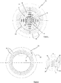
- a rotating electrical machine here a synchronous machine with variable reluctance assisted by a permanent magnet, comprises a rotor 10 and a stator 12 nested one in the other by being coaxial.
- the rotor comprises, in a manner known per se, a shaft 14, preferably magnetic, on which is placed a stack of identical flat ferromagnetic sheets 16, which are assembled to each other by any known means.
- the circularly shaped sheets 16 comprise a central bore 18 through which the rotor shaft 14 passes and a plurality of axial recesses 20 which pass right through the sheets.
- the other series of recesses consists of perforations 26 in an inclined radial direction, which start from these housings to arrive in the vicinity of the edge of the sheets.
- the inclined perforations are arranged symmetrically with respect to the housings 22 of the magnets.
- a geometric figure which is substantially V-shaped with a flattened bottom with the flat bottom formed by the housing 22 and with the inclined arms of this V formed by the perforations 26.
- the stator 12 comprises an annular ring 30 with an internal wall 32, the internal diameter of which is designed to receive the rotor 10 with a space necessary to form an air gap 34, and an external wall 33.
- This ring comprises a multiplicity of bores 36, here of oblong section, which form closed notches for the armature windings.
- these bores extend axially along the length of the stator while being disposed radially on the ring while being placed circumferentially at a distance from each other by a distance D.
- these oblong bores have a lower wall 38 of semi-circular shape which is located at a distance E from the internal wall 32 of the stator, a high wall 40 also of semi-circular shape, here of greater diametral dimension to that of the bottom wall, and at a distance from the outer wall 33 of the stator, and two side faces 42 connecting the ends of the semi-circular walls.
- the distance E has a minimum value of 0.35 mm and a maximum value between 0.5 mm and 1 mm.
- the wall 32 is a continuous wall and the air gap 34 is almost constant between the rotor and the stator and that over the entire circumference.
- these bores can have a section other than an oblong section, such as a cylindrical section.
- top and bottom walls of the notches are of the same diametrical dimension, forming a closed line such as a circle or an oval.
- FIG 3 is a graph with curves illustrating the torque of the electric machine (in Nm) with respect to the electric position of the rotor (in °) for a constant current, for a machine of the prior art (dotted line) with open notches of the stator and for a machine according to the invention (strong line) with closed notches of the stator, it can be observed that the variations in the torque of the machine, essentially due to the effects of notches, are greatly reduced for a machine according to the invention compared to a machine of the prior art.
- the figure 4 is a graph with curves illustrating the instantaneous torque of the electric machine (in Nm) with respect to the electric position of the machine (in °) for a constant current and a constant defluxing angle, for a machine with open notches of the stator (prior art) and for a machine according to the invention with closed notches of the stator.
Description
La présente invention se rapporte à une machine électrique tournante avec un stator à encoches fermées et plus particulièrement à une machine électrique synchrone à réluctance variable assistée d'aimants permanents.The present invention relates to a rotating electrical machine with a stator with closed slots and more particularly to a synchronous electrical machine with variable reluctance assisted by permanent magnets.
Généralement, une telle machine électrique comporte un stator et un rotor disposés coaxialement l'un dans l'autre.Generally, such an electric machine comprises a stator and a rotor arranged coaxially one inside the other.
Le rotor est formé d'un corps de rotor avec un empilage de tôles placé sur un arbre de rotor. Ces tôles comprennent des logements pour des aimants permanents et des perforations pour créer de barrières de flux permettant de diriger radialement le flux magnétique des aimants vers le stator.The rotor is formed by a rotor body with a stack of sheets placed on a rotor shaft. These sheets include housings for permanent magnets and perforations to create flux barriers making it possible to direct the magnetic flux from the magnets radially towards the stator.
Ce rotor est généralement logé à l'intérieur d'un stator qui porte des bobinages électriques permettant de générer un champ magnétique permettant d'entrainer en rotation le rotor.This rotor is generally housed inside a stator which carries electrical windings making it possible to generate a magnetic field making it possible to drive the rotor in rotation.
Comme cela est mieux décrit dans le document
Ces encoches sont prévues pour recevoir des bobinages d'induit qui sont introduits dans le stator par la face ouverte des encoches puis y sont fixés par tous moyens connus.These notches are designed to receive armature windings which are introduced into the stator via the open face of the notches and then are fixed thereto by any known means.
De manière générale, l'ondulation du couple est importante dans ce type de machine synchrone à reluctance assistée d'aimants permanents.In general, the torque ripple is important in this type of synchronous machine with reluctance assisted by permanent magnets.
Ceci peut générer des à-coups et des vibrations au niveau du rotor en entrainant un inconfort d'utilisation de cette machine.This can generate jerks and vibrations at the rotor level, causing discomfort in the use of this machine.
Le document
A cet effet, la présente invention concerne une machine électrique selon la revendication 1.To this end, the present invention relates to an electric machine according to
Les encoches s'étendent axialement le long du stator.The notches extend axially along the stator.
Les encoches présentent une section oblongue avec une paroi basse à distance de la paroi du stator, une paroi haute et deux faces reliant les parois.The notches have an oblong section with a low wall at a distance from the wall of the stator, a high wall and two faces connecting the walls.
Le rotor peut comprendre des logements pour des générateurs de flux magnétique et des évidements formant des barrières de flux.The rotor can include housings for magnetic flux generators and recesses forming flux barriers.
Les autres caractéristiques et avantages de l'invention vont apparaître maintenant à la lecture de la description qui va suivre, donnée à titre uniquement illustratif et non limitatif, et à laquelle sont annexées :
- la
figure 1 qui est une vue schématique en coupe transversale de la machine électrique selon l'invention, - la
figure 2 qui est une vue schématique en coupe transversale du stator de la machine de lafigure 1 avec une section locale selon la ligne fermé A, - la
figure 3 qui est un graphique illustrant l'évolution du couple à courant constant en fonction de la position électrique du rotor pour une machine électrique de l'art antérieur et pour une machine électrique selon l'invention et - la
figure 4 qui est un graphique avec des courbes illustrant le couple instantanée de la machine électrique (en N.m) par rapport à la position électrique de la machine.
- the
figure 1 which is a schematic cross-sectional view of the electric machine according to the invention, - the
figure 2 which is a schematic cross-sectional view of the stator of the machine of thefigure 1 with a local section on the closed line A, - the
figure 3 which is a graph illustrating the evolution of the torque at constant current as a function of the electrical position of the rotor for an electrical machine of the prior art and for an electrical machine according to the invention and - the
figure 4 which is a graph with curves illustrating the instantaneous torque of the electric machine (in Nm) with respect to the electric position of the machine.
Comme illustré sur la
Le rotor comporte, de manière connue en soi, un arbre 14, de préférence magnétique, sur lequel est placé un empilage de tôles ferromagnétiques planes identiques 16, qui sont assemblées les unes aux autres par tous moyens connus.The rotor comprises, in a manner known per se, a
Les tôles 16 de forme circulaire comprennent un alésage central 18 traversé par l'arbre de rotor 14 et une pluralité d'évidements axiaux 20 qui traversent les tôles de part en part.The circularly
Une première série d'évidements axiaux rectangulaires 22, disposés radialement les uns au-dessus des autres et à distance les uns des autres, forment des logements pour des générateurs de flux magnétiques, ici des aimants permanents 24 sous forme de barreau également rectangulaire de longueur sensiblement égale à la longueur de l'empilage de tôles.A first series of rectangular
L'autre série d'évidements consiste en des perforations 26 de direction radiale inclinée, qui partent de ces logements pour arriver au voisinage du bord des tôles.The other series of recesses consists of
Tel que cela est représenté sur la
Il se crée ainsi des barrières de flux 28 formées par les perforations. Le flux magnétique provenant des aimants ne peut alors que transiter par les parties pleines entre les perforations.It thus creates
En se rapportant en plus à la
Cette bague comprend une multiplicité de perçages 36, ici de section oblongue, qui forment des encoches fermées pour les bobinages d'induit.This ring comprises a multiplicity of
Plus précisément, ces perçages s'étendent axialement tout au long du stator en étant disposés radialement sur la bague tout en étant placés circonférentiellement à distance les uns des autres d'une distance D.More precisely, these bores extend axially along the length of the stator while being disposed radially on the ring while being placed circumferentially at a distance from each other by a distance D.
Dans l'exemple décrit, ces perçages oblongs présentent une paroi basse 38 de forme semi-circulaire qui est située à une distance E de la paroi interne 32 du stator, une paroi haute 40 de forme également semi-circulaire, ici de dimension diamétrale supérieure à celle de la paroi basse, et à distance de la paroi externe 33 du stator, et deux faces latérales 42 reliant les extrémités des parois semi-circulaires.In the example described, these oblong bores have a
Avantageusement, la distance E est d'une valeur minimale de 0,35mm et d'une valeur maximale entre 0,5 mm et 1 mm.Advantageously, the distance E has a minimum value of 0.35 mm and a maximum value between 0.5 mm and 1 mm.
Par cela, il est créé un volume fermé qui forme une encoche fermé pour recevoir le bobinage d'induit.By this, a closed volume is created which forms a closed notch to receive the armature coil.
Ainsi, la paroi 32 est une paroi continue et l'entrefer 34 est quasiment constant entre le rotor et le stator et cela sur toute la circonférence.Thus, the
De plus, comme l'extérieur du rotor et l'intérieur du stator sont lisses, cela permet d'avoir un bruit aérodynamique réduit.In addition, since the exterior of the rotor and the interior of the stator are smooth, this results in reduced aerodynamic noise.
Bien entendu et cela sans sortir du cadre de l'invention, ces perçages peuvent avoir une section autre qu'une section oblongue, telle qu'une section cylindrique.Of course, and without departing from the scope of the invention, these bores can have a section other than an oblong section, such as a cylindrical section.
Dans ce cas, les parois haute et basse des encoches sont de même dimension diamétrale en formant une ligne fermée tel qu'un cercle ou un ovale.In this case, the top and bottom walls of the notches are of the same diametrical dimension, forming a closed line such as a circle or an oval.
En se référant maintenant à la
La
Sur cette figure, il peut être constaté que les variations (ou ondulations) du couple de la machine électrique selon l'invention sont fortement diminués par rapport à une machine électrique selon l'art antérieur.In this figure, it can be seen that the variations (or ripples) of the torque of the electric machine according to the invention are greatly reduced compared to an electric machine according to the prior art.
Claims (4)
- Electric machine comprising a rotor (10) and a stator (12) comprising an internal wall (32) facing the rotor, said stator bearing a multitude of radial slots arranged circumferentially along said stator, characterized in that the slots (36) comprise a bottom wall (38) of semi-circular shape and at a distance (E) from the internal wall of the stator, a top wall (40) of semi-circular shape of diametral dimension greater than that of the bottom wall (38) and at a distance from the external wall (33) of the stator and two faces (42) connecting the bottom (38) and the top (40) walls so as to form a multitude of closed slots.
- Electric machine according to Claim 1, characterized in that the slots extend axially along the stator.
- Electric machine according to Claim 1 or 2, characterized in that the slots have an oblong cross section with a bottom wall (38) at a distance (E) from the wall of the stator, a top wall (40) and two faces (42) connecting the walls.
- Electric machine according to Claim 1, characterized in that the rotor (10) comprises housings for magnetic-flux generators (24) and recesses (26) forming flux barriers (28).
Applications Claiming Priority (2)
| Application Number | Priority Date | Filing Date | Title |
|---|---|---|---|
| FR1554835A FR3036870B1 (en) | 2015-05-28 | 2015-05-28 | ROTATING ELECTRIC MACHINE WITH A STATOR WITH CLOSED NOTCHES AND MORE PARTICULARLY SYNCHRONOUS ELECTRIC MACHINE WITH VARIABLE RELUCTANCE ASSISTED WITH PERMANENT MAGNETS. |
| PCT/EP2016/060697 WO2016188764A1 (en) | 2015-05-28 | 2016-05-12 | Rotating electric machine with a stator with closed notches and more particularly variable-reluctance synchronous electric machine assisted by permanent magnets |
Publications (2)
| Publication Number | Publication Date |
|---|---|
| EP3304706A1 EP3304706A1 (en) | 2018-04-11 |
| EP3304706B1 true EP3304706B1 (en) | 2020-10-28 |
Family
ID=54329638
Family Applications (1)
| Application Number | Title | Priority Date | Filing Date |
|---|---|---|---|
| EP16722654.7A Active EP3304706B1 (en) | 2015-05-28 | 2016-05-12 | Rotating electric machine with a stator with closed notches and more particularly variable-reluctance synchronous electric machine assisted by permanent magnets |
Country Status (6)
| Country | Link |
|---|---|
| US (1) | US20180159387A1 (en) |
| EP (1) | EP3304706B1 (en) |
| JP (1) | JP6783800B2 (en) |
| CN (1) | CN207732602U (en) |
| FR (1) | FR3036870B1 (en) |
| WO (1) | WO2016188764A1 (en) |
Families Citing this family (15)
| Publication number | Priority date | Publication date | Assignee | Title |
|---|---|---|---|---|
| FR3062253B1 (en) * | 2017-01-25 | 2020-06-12 | IFP Energies Nouvelles | CLOSED ROTATING ELECTRIC MACHINE WITH AN AIR COOLING SYSTEM OF THE MAGNETS IN THE ROTOR |
| FR3063398A1 (en) | 2017-02-24 | 2018-08-31 | IFP Energies Nouvelles | ROTATING ELECTRICAL MACHINE WITH A STATOR WITH ENCLOSED NOTCHES AND, MORE PARTICULARLY, RELUCTANT SYNCHRO ELECTRICAL MACHINE ASSISTED WITH PERMANENT MAGNETS |
| FR3066657B1 (en) * | 2017-05-16 | 2019-06-14 | IFP Energies Nouvelles | ELECTRIC MACHINE COMPRISING A ROTOR ROTOR TREE AND METHOD OF MANUFACTURING SUCH A MACHINE |
| FR3071371B1 (en) * | 2017-09-18 | 2019-09-13 | IFP Energies Nouvelles | GEOMETRY OF MAGNETIC BRIDGES OF AN ELECTRIC MACHINE ROTOR |
| FR3071370B1 (en) | 2017-09-18 | 2019-09-13 | IFP Energies Nouvelles | ISTHMA OF MAGNETIC BRIDGES OF AN ELECTRIC MACHINE ROTOR |
| FR3084535B1 (en) | 2018-07-24 | 2020-07-17 | IFP Energies Nouvelles | ELECTRIC MACHINE ROTOR WITH ASYMMETRIC POLES |
| FR3084534B1 (en) | 2018-07-24 | 2020-07-17 | IFP Energies Nouvelles | ROTOR OF ELECTRIC MACHINE WITH ASYMMETRIC MAGNETIC BRIDGES |
| FR3094583B1 (en) | 2019-03-29 | 2021-03-12 | Ifp Energies Now | Electric machine rotor with asymmetric poles and side magnets |
| EP3742583A1 (en) * | 2019-05-22 | 2020-11-25 | Siemens Aktiengesellschaft | Quadrupole synchronous reluctance machine |
| CN114731065A (en) * | 2019-11-12 | 2022-07-08 | 马威动力控制技术股份公司 | Synchronous motor using permanent magnet assisted magnetic resistance and manufacturing method thereof |
| FR3104848B1 (en) | 2019-12-17 | 2021-11-26 | Ifp Energies Now | Synchro-reluctant machine with variable air gap |
| US11677283B2 (en) | 2020-08-04 | 2023-06-13 | Ford Global Technologies, Llc | Electric machine having vibration attenuating stator laminations |
| FR3115639B1 (en) | 2020-10-22 | 2023-04-21 | Ifp Energies Now | Synchro-reluctant electric machine with open tangential bridges |
| FR3115946A1 (en) | 2020-11-05 | 2022-05-06 | IFP Energies Nouvelles | Electrical machine rotor with shutter mask in a flux barrier |
| EP4272296A1 (en) | 2020-12-31 | 2023-11-08 | Mavel edt S.p.A. | Stator with closed slots with continuous winding for an electric machine and process for making such stator |
Family Cites Families (9)
| Publication number | Priority date | Publication date | Assignee | Title |
|---|---|---|---|---|
| US4160926A (en) * | 1975-06-20 | 1979-07-10 | The Epoxylite Corporation | Materials and impregnating compositions for insulating electric machines |
| JP2782044B2 (en) * | 1994-12-21 | 1998-07-30 | セイコー精機株式会社 | Spindle motor |
| WO2002031947A1 (en) * | 2000-10-12 | 2002-04-18 | Matsushita Electric Industrial Co., Ltd. | Electric motor |
| KR100591338B1 (en) * | 2004-08-26 | 2006-06-19 | 엘지전자 주식회사 | Permanent Magnet Assisted SynRM and its method for impressing flux |
| KR20060064310A (en) * | 2004-12-08 | 2006-06-13 | 삼성전자주식회사 | A magnet motor |
| US20110175482A1 (en) * | 2010-01-20 | 2011-07-21 | Savagian Peter J | Optimized stator tooth tip for a motor with axially inserted stator windings |
| FR2973179B1 (en) * | 2011-03-21 | 2014-09-05 | Renault Sa | ELECTRICAL MACHINE WITH REDUCED TORQUE OVERRIDE |
| JP5745379B2 (en) * | 2011-10-04 | 2015-07-08 | 日立オートモティブシステムズ株式会社 | Rotating electric machine and electric vehicle |
| WO2014027630A1 (en) * | 2012-08-16 | 2014-02-20 | 株式会社ミツバ | Rotor for use in magnet-assisted reluctance motor, and brushless motor |
-
2015
- 2015-05-28 FR FR1554835A patent/FR3036870B1/en active Active
-
2016
- 2016-05-12 WO PCT/EP2016/060697 patent/WO2016188764A1/en active Application Filing
- 2016-05-12 EP EP16722654.7A patent/EP3304706B1/en active Active
- 2016-05-12 CN CN201690000072.9U patent/CN207732602U/en active Active
- 2016-05-12 US US15/577,689 patent/US20180159387A1/en not_active Abandoned
- 2016-05-12 JP JP2017559033A patent/JP6783800B2/en active Active
Non-Patent Citations (1)
| Title |
|---|
| None * |
Also Published As
| Publication number | Publication date |
|---|---|
| EP3304706A1 (en) | 2018-04-11 |
| FR3036870B1 (en) | 2020-05-01 |
| US20180159387A1 (en) | 2018-06-07 |
| WO2016188764A1 (en) | 2016-12-01 |
| JP2018516055A (en) | 2018-06-14 |
| FR3036870A1 (en) | 2016-12-02 |
| JP6783800B2 (en) | 2020-11-11 |
| CN207732602U (en) | 2018-08-14 |
Similar Documents
| Publication | Publication Date | Title |
|---|---|---|
| EP3304706B1 (en) | Rotating electric machine with a stator with closed notches and more particularly variable-reluctance synchronous electric machine assisted by permanent magnets | |
| FR3084535A1 (en) | ELECTRIC MACHINE ROTOR WITH ASYMMETRIC POLES | |
| EP3104501B1 (en) | Rotor for rotary electric machine | |
| EP3286823B1 (en) | Electric machine and method for dynamically balancing the rotor of such electric machine | |
| EP3685498B1 (en) | Geometry of magnetic bridges of an electrical machine rotor | |
| EP3949082A1 (en) | Rotor for an electrical machine, having asymmetric poles and lateral magnets | |
| FR3036006B1 (en) | ROTOR OF ROTATING ELECTRIC MACHINE PROVIDED WITH AT LEAST ONE FOLDING MEMBER OF A MAGNET WITHIN A CORRESPONDING CAVITY | |
| FR3066657B1 (en) | ELECTRIC MACHINE COMPRISING A ROTOR ROTOR TREE AND METHOD OF MANUFACTURING SUCH A MACHINE | |
| EP3685492B1 (en) | Isthmi for the magnetic bridges of an electric machine rotor | |
| EP3028368A2 (en) | Rotor with permanent magnets | |
| EP3229348B1 (en) | Rotor for an electrical machine | |
| EP3382856A1 (en) | Rotary electrical machine with improved cooling | |
| EP3607640B1 (en) | Rotor for electric machine with internal permanent magnets | |
| WO2017001377A1 (en) | Rotary electric machine with a rotor that limits magnetic flux losses, notably electric motor | |
| FR3037734B1 (en) | ROTOR WITH STACKED SHEETS. | |
| FR3036007B1 (en) | IMPROVED ROTOR OF ELECTRIC ROTATING MACHINE COMPRISING AT LEAST ONE MAGNET PLATING ELEMENT | |
| WO2018042124A1 (en) | Rotor for a rotary electric machine provided with at least one deformable portion for filling a cavity | |
| WO2016146909A1 (en) | Rotor of an electrical rotating machine with an optimised configuration of permanent magnets | |
| EP3586425A1 (en) | Rotating electric machine comprising a stator with sealed slots, and more particularly permanent magnet-assisted reluctant synchronous electric machine | |
| WO2016146910A1 (en) | Rotor of a rotary electric machine with optimised placement of attachment means | |
| FR3040560A1 (en) | ROTOR FOR ROTATING ELECTRIC MACHINE | |
| FR3050587A1 (en) | ROTATING ELECTRIC MACHINE HAVING AN ELECTRICAL CONDUCTOR FOR CONNECTING WINDINGS | |
| FR2988235A1 (en) | Brushless electric motor for managing and actuating aerators in car, has space inter-magnet defined by angle formed between adjacent side faces of magnets, where angle from space inter-magnet is calculated for measuring thickness of air gap |
Legal Events
| Date | Code | Title | Description |
|---|---|---|---|
| STAA | Information on the status of an ep patent application or granted ep patent |
Free format text: STATUS: THE INTERNATIONAL PUBLICATION HAS BEEN MADE |
|
| PUAI | Public reference made under article 153(3) epc to a published international application that has entered the european phase |
Free format text: ORIGINAL CODE: 0009012 |
|
| STAA | Information on the status of an ep patent application or granted ep patent |
Free format text: STATUS: REQUEST FOR EXAMINATION WAS MADE |
|
| 17P | Request for examination filed |
Effective date: 20180102 |
|
| AK | Designated contracting states |
Kind code of ref document: A1 Designated state(s): AL AT BE BG CH CY CZ DE DK EE ES FI FR GB GR HR HU IE IS IT LI LT LU LV MC MK MT NL NO PL PT RO RS SE SI SK SM TR |
|
| AX | Request for extension of the european patent |
Extension state: BA ME |
|
| DAV | Request for validation of the european patent (deleted) | ||
| DAX | Request for extension of the european patent (deleted) | ||
| GRAP | Despatch of communication of intention to grant a patent |
Free format text: ORIGINAL CODE: EPIDOSNIGR1 |
|
| STAA | Information on the status of an ep patent application or granted ep patent |
Free format text: STATUS: GRANT OF PATENT IS INTENDED |
|
| INTG | Intention to grant announced |
Effective date: 20200108 |
|
| GRAS | Grant fee paid |
Free format text: ORIGINAL CODE: EPIDOSNIGR3 |
|
| GRAA | (expected) grant |
Free format text: ORIGINAL CODE: 0009210 |
|
| STAA | Information on the status of an ep patent application or granted ep patent |
Free format text: STATUS: THE PATENT HAS BEEN GRANTED |
|
| AK | Designated contracting states |
Kind code of ref document: B1 Designated state(s): AL AT BE BG CH CY CZ DE DK EE ES FI FR GB GR HR HU IE IS IT LI LT LU LV MC MK MT NL NO PL PT RO RS SE SI SK SM TR |
|
| REG | Reference to a national code |
Ref country code: GB Ref legal event code: FG4D Free format text: NOT ENGLISH |
|
| REG | Reference to a national code |
Ref country code: CH Ref legal event code: EP |
|
| REG | Reference to a national code |
Ref country code: AT Ref legal event code: REF Ref document number: 1329229 Country of ref document: AT Kind code of ref document: T Effective date: 20201115 |
|
| REG | Reference to a national code |
Ref country code: DE Ref legal event code: R096 Ref document number: 602016046674 Country of ref document: DE |
|
| REG | Reference to a national code |
Ref country code: IE Ref legal event code: FG4D Free format text: LANGUAGE OF EP DOCUMENT: FRENCH |
|
| REG | Reference to a national code |
Ref country code: AT Ref legal event code: MK05 Ref document number: 1329229 Country of ref document: AT Kind code of ref document: T Effective date: 20201028 |
|
| REG | Reference to a national code |
Ref country code: NL Ref legal event code: MP Effective date: 20201028 |
|
| PG25 | Lapsed in a contracting state [announced via postgrant information from national office to epo] |
Ref country code: GR Free format text: LAPSE BECAUSE OF FAILURE TO SUBMIT A TRANSLATION OF THE DESCRIPTION OR TO PAY THE FEE WITHIN THE PRESCRIBED TIME-LIMIT Effective date: 20210129 Ref country code: FI Free format text: LAPSE BECAUSE OF FAILURE TO SUBMIT A TRANSLATION OF THE DESCRIPTION OR TO PAY THE FEE WITHIN THE PRESCRIBED TIME-LIMIT Effective date: 20201028 Ref country code: PT Free format text: LAPSE BECAUSE OF FAILURE TO SUBMIT A TRANSLATION OF THE DESCRIPTION OR TO PAY THE FEE WITHIN THE PRESCRIBED TIME-LIMIT Effective date: 20210301 Ref country code: RS Free format text: LAPSE BECAUSE OF FAILURE TO SUBMIT A TRANSLATION OF THE DESCRIPTION OR TO PAY THE FEE WITHIN THE PRESCRIBED TIME-LIMIT Effective date: 20201028 Ref country code: NO Free format text: LAPSE BECAUSE OF FAILURE TO SUBMIT A TRANSLATION OF THE DESCRIPTION OR TO PAY THE FEE WITHIN THE PRESCRIBED TIME-LIMIT Effective date: 20210128 |
|
| REG | Reference to a national code |
Ref country code: LT Ref legal event code: MG4D |
|
| PG25 | Lapsed in a contracting state [announced via postgrant information from national office to epo] |
Ref country code: AT Free format text: LAPSE BECAUSE OF FAILURE TO SUBMIT A TRANSLATION OF THE DESCRIPTION OR TO PAY THE FEE WITHIN THE PRESCRIBED TIME-LIMIT Effective date: 20201028 Ref country code: ES Free format text: LAPSE BECAUSE OF FAILURE TO SUBMIT A TRANSLATION OF THE DESCRIPTION OR TO PAY THE FEE WITHIN THE PRESCRIBED TIME-LIMIT Effective date: 20201028 Ref country code: IS Free format text: LAPSE BECAUSE OF FAILURE TO SUBMIT A TRANSLATION OF THE DESCRIPTION OR TO PAY THE FEE WITHIN THE PRESCRIBED TIME-LIMIT Effective date: 20210228 Ref country code: LV Free format text: LAPSE BECAUSE OF FAILURE TO SUBMIT A TRANSLATION OF THE DESCRIPTION OR TO PAY THE FEE WITHIN THE PRESCRIBED TIME-LIMIT Effective date: 20201028 Ref country code: PL Free format text: LAPSE BECAUSE OF FAILURE TO SUBMIT A TRANSLATION OF THE DESCRIPTION OR TO PAY THE FEE WITHIN THE PRESCRIBED TIME-LIMIT Effective date: 20201028 Ref country code: BG Free format text: LAPSE BECAUSE OF FAILURE TO SUBMIT A TRANSLATION OF THE DESCRIPTION OR TO PAY THE FEE WITHIN THE PRESCRIBED TIME-LIMIT Effective date: 20210128 Ref country code: SE Free format text: LAPSE BECAUSE OF FAILURE TO SUBMIT A TRANSLATION OF THE DESCRIPTION OR TO PAY THE FEE WITHIN THE PRESCRIBED TIME-LIMIT Effective date: 20201028 |
|
| PG25 | Lapsed in a contracting state [announced via postgrant information from national office to epo] |
Ref country code: HR Free format text: LAPSE BECAUSE OF FAILURE TO SUBMIT A TRANSLATION OF THE DESCRIPTION OR TO PAY THE FEE WITHIN THE PRESCRIBED TIME-LIMIT Effective date: 20201028 Ref country code: NL Free format text: LAPSE BECAUSE OF FAILURE TO SUBMIT A TRANSLATION OF THE DESCRIPTION OR TO PAY THE FEE WITHIN THE PRESCRIBED TIME-LIMIT Effective date: 20201028 |
|
| REG | Reference to a national code |
Ref country code: DE Ref legal event code: R097 Ref document number: 602016046674 Country of ref document: DE |
|
| PG25 | Lapsed in a contracting state [announced via postgrant information from national office to epo] |
Ref country code: SM Free format text: LAPSE BECAUSE OF FAILURE TO SUBMIT A TRANSLATION OF THE DESCRIPTION OR TO PAY THE FEE WITHIN THE PRESCRIBED TIME-LIMIT Effective date: 20201028 Ref country code: LT Free format text: LAPSE BECAUSE OF FAILURE TO SUBMIT A TRANSLATION OF THE DESCRIPTION OR TO PAY THE FEE WITHIN THE PRESCRIBED TIME-LIMIT Effective date: 20201028 Ref country code: EE Free format text: LAPSE BECAUSE OF FAILURE TO SUBMIT A TRANSLATION OF THE DESCRIPTION OR TO PAY THE FEE WITHIN THE PRESCRIBED TIME-LIMIT Effective date: 20201028 Ref country code: CZ Free format text: LAPSE BECAUSE OF FAILURE TO SUBMIT A TRANSLATION OF THE DESCRIPTION OR TO PAY THE FEE WITHIN THE PRESCRIBED TIME-LIMIT Effective date: 20201028 Ref country code: RO Free format text: LAPSE BECAUSE OF FAILURE TO SUBMIT A TRANSLATION OF THE DESCRIPTION OR TO PAY THE FEE WITHIN THE PRESCRIBED TIME-LIMIT Effective date: 20201028 Ref country code: SK Free format text: LAPSE BECAUSE OF FAILURE TO SUBMIT A TRANSLATION OF THE DESCRIPTION OR TO PAY THE FEE WITHIN THE PRESCRIBED TIME-LIMIT Effective date: 20201028 |
|
| PG25 | Lapsed in a contracting state [announced via postgrant information from national office to epo] |
Ref country code: DK Free format text: LAPSE BECAUSE OF FAILURE TO SUBMIT A TRANSLATION OF THE DESCRIPTION OR TO PAY THE FEE WITHIN THE PRESCRIBED TIME-LIMIT Effective date: 20201028 |
|
| PLBE | No opposition filed within time limit |
Free format text: ORIGINAL CODE: 0009261 |
|
| STAA | Information on the status of an ep patent application or granted ep patent |
Free format text: STATUS: NO OPPOSITION FILED WITHIN TIME LIMIT |
|
| 26N | No opposition filed |
Effective date: 20210729 |
|
| PG25 | Lapsed in a contracting state [announced via postgrant information from national office to epo] |
Ref country code: AL Free format text: LAPSE BECAUSE OF FAILURE TO SUBMIT A TRANSLATION OF THE DESCRIPTION OR TO PAY THE FEE WITHIN THE PRESCRIBED TIME-LIMIT Effective date: 20201028 |
|
| PG25 | Lapsed in a contracting state [announced via postgrant information from national office to epo] |
Ref country code: SI Free format text: LAPSE BECAUSE OF FAILURE TO SUBMIT A TRANSLATION OF THE DESCRIPTION OR TO PAY THE FEE WITHIN THE PRESCRIBED TIME-LIMIT Effective date: 20201028 |
|
| REG | Reference to a national code |
Ref country code: CH Ref legal event code: PL |
|
| PG25 | Lapsed in a contracting state [announced via postgrant information from national office to epo] |
Ref country code: MC Free format text: LAPSE BECAUSE OF FAILURE TO SUBMIT A TRANSLATION OF THE DESCRIPTION OR TO PAY THE FEE WITHIN THE PRESCRIBED TIME-LIMIT Effective date: 20201028 Ref country code: LU Free format text: LAPSE BECAUSE OF NON-PAYMENT OF DUE FEES Effective date: 20210512 Ref country code: LI Free format text: LAPSE BECAUSE OF NON-PAYMENT OF DUE FEES Effective date: 20210531 Ref country code: CH Free format text: LAPSE BECAUSE OF NON-PAYMENT OF DUE FEES Effective date: 20210531 |
|
| REG | Reference to a national code |
Ref country code: BE Ref legal event code: MM Effective date: 20210531 |
|
| PG25 | Lapsed in a contracting state [announced via postgrant information from national office to epo] |
Ref country code: IE Free format text: LAPSE BECAUSE OF NON-PAYMENT OF DUE FEES Effective date: 20210512 |
|
| PG25 | Lapsed in a contracting state [announced via postgrant information from national office to epo] |
Ref country code: IS Free format text: LAPSE BECAUSE OF FAILURE TO SUBMIT A TRANSLATION OF THE DESCRIPTION OR TO PAY THE FEE WITHIN THE PRESCRIBED TIME-LIMIT Effective date: 20210228 Ref country code: FR Free format text: LAPSE BECAUSE OF NON-PAYMENT OF DUE FEES Effective date: 20210531 |
|
| PG25 | Lapsed in a contracting state [announced via postgrant information from national office to epo] |
Ref country code: BE Free format text: LAPSE BECAUSE OF NON-PAYMENT OF DUE FEES Effective date: 20210531 |
|
| PG25 | Lapsed in a contracting state [announced via postgrant information from national office to epo] |
Ref country code: CY Free format text: LAPSE BECAUSE OF FAILURE TO SUBMIT A TRANSLATION OF THE DESCRIPTION OR TO PAY THE FEE WITHIN THE PRESCRIBED TIME-LIMIT Effective date: 20201028 |
|
| PG25 | Lapsed in a contracting state [announced via postgrant information from national office to epo] |
Ref country code: HU Free format text: LAPSE BECAUSE OF FAILURE TO SUBMIT A TRANSLATION OF THE DESCRIPTION OR TO PAY THE FEE WITHIN THE PRESCRIBED TIME-LIMIT; INVALID AB INITIO Effective date: 20160512 |
|
| PGFP | Annual fee paid to national office [announced via postgrant information from national office to epo] |
Ref country code: IT Payment date: 20230420 Year of fee payment: 8 Ref country code: DE Payment date: 20230526 Year of fee payment: 8 |
|
| PGFP | Annual fee paid to national office [announced via postgrant information from national office to epo] |
Ref country code: GB Payment date: 20230529 Year of fee payment: 8 |