EP3684985B1 - Bewehrungsmaterial - Google Patents
Bewehrungsmaterial Download PDFInfo
- Publication number
- EP3684985B1 EP3684985B1 EP18781953.7A EP18781953A EP3684985B1 EP 3684985 B1 EP3684985 B1 EP 3684985B1 EP 18781953 A EP18781953 A EP 18781953A EP 3684985 B1 EP3684985 B1 EP 3684985B1
- Authority
- EP
- European Patent Office
- Prior art keywords
- rovings
- transverse
- longitudinal
- reinforcement
- thread
- Prior art date
- Legal status (The legal status is an assumption and is not a legal conclusion. Google has not performed a legal analysis and makes no representation as to the accuracy of the status listed.)
- Active
Links
Images
Classifications
-
- E—FIXED CONSTRUCTIONS
- E04—BUILDING
- E04C—STRUCTURAL ELEMENTS; BUILDING MATERIALS
- E04C5/00—Reinforcing elements, e.g. for concrete; Auxiliary elements therefor
- E04C5/07—Reinforcing elements of material other than metal, e.g. of glass, of plastics, or not exclusively made of metal
-
- B—PERFORMING OPERATIONS; TRANSPORTING
- B29—WORKING OF PLASTICS; WORKING OF SUBSTANCES IN A PLASTIC STATE IN GENERAL
- B29B—PREPARATION OR PRETREATMENT OF THE MATERIAL TO BE SHAPED; MAKING GRANULES OR PREFORMS; RECOVERY OF PLASTICS OR OTHER CONSTITUENTS OF WASTE MATERIAL CONTAINING PLASTICS
- B29B11/00—Making preforms
- B29B11/14—Making preforms characterised by structure or composition
- B29B11/16—Making preforms characterised by structure or composition comprising fillers or reinforcement
-
- B—PERFORMING OPERATIONS; TRANSPORTING
- B29—WORKING OF PLASTICS; WORKING OF SUBSTANCES IN A PLASTIC STATE IN GENERAL
- B29C—SHAPING OR JOINING OF PLASTICS; SHAPING OF MATERIAL IN A PLASTIC STATE, NOT OTHERWISE PROVIDED FOR; AFTER-TREATMENT OF THE SHAPED PRODUCTS, e.g. REPAIRING
- B29C70/00—Shaping composites, i.e. plastics material comprising reinforcements, fillers or preformed parts, e.g. inserts
-
- D—TEXTILES; PAPER
- D04—BRAIDING; LACE-MAKING; KNITTING; TRIMMINGS; NON-WOVEN FABRICS
- D04H—MAKING TEXTILE FABRICS, e.g. FROM FIBRES OR FILAMENTARY MATERIAL; FABRICS MADE BY SUCH PROCESSES OR APPARATUS, e.g. FELTS, NON-WOVEN FABRICS; COTTON-WOOL; WADDING ; NON-WOVEN FABRICS FROM STAPLE FIBRES, FILAMENTS OR YARNS, BONDED WITH AT LEAST ONE WEB-LIKE MATERIAL DURING THEIR CONSOLIDATION
- D04H13/00—Other non-woven fabrics
-
- B—PERFORMING OPERATIONS; TRANSPORTING
- B29—WORKING OF PLASTICS; WORKING OF SUBSTANCES IN A PLASTIC STATE IN GENERAL
- B29C—SHAPING OR JOINING OF PLASTICS; SHAPING OF MATERIAL IN A PLASTIC STATE, NOT OTHERWISE PROVIDED FOR; AFTER-TREATMENT OF THE SHAPED PRODUCTS, e.g. REPAIRING
- B29C70/00—Shaping composites, i.e. plastics material comprising reinforcements, fillers or preformed parts, e.g. inserts
- B29C70/04—Shaping composites, i.e. plastics material comprising reinforcements, fillers or preformed parts, e.g. inserts comprising reinforcements only, e.g. self-reinforcing plastics
- B29C70/06—Fibrous reinforcements only
- B29C70/10—Fibrous reinforcements only characterised by the structure of fibrous reinforcements, e.g. hollow fibres
- B29C70/16—Fibrous reinforcements only characterised by the structure of fibrous reinforcements, e.g. hollow fibres using fibres of substantial or continuous length
- B29C70/22—Fibrous reinforcements only characterised by the structure of fibrous reinforcements, e.g. hollow fibres using fibres of substantial or continuous length oriented in at least two directions forming a two-dimensional [2D] structure
Definitions
- the present invention relates to a reinforcement for a hardening matrix, in particular concrete, comprising a lattice structure made of rovings, wherein the rovings are arranged in several tracks and form crossing points.
- the invention further relates to a method for producing a reinforcement, in particular for a hardening matrix such as concrete, comprising a lattice structure made of rovings.
- the invention relates to textile concrete, comprising such a reinforcement, the production of textile concrete and possible uses of the reinforcement.
- Concrete is the most commonly used building material in construction and is characterized by high compressive strength. Since its tensile strength is only about 10% of the compressive strength, the majority of concrete components must be supplemented with reinforcement that is suitable for absorbing tensile forces and works in the concrete composite. Steel is mainly used as reinforcement, but this is disadvantageous. Steel corrosion, which is the most common cause of damage to reinforced concrete components, leads to a limited service life. To prevent steel corrosion, sufficient concrete cover is required, which leads to greater component thicknesses and additional structural dead weight.
- Textiles have also been used as an alternative reinforcement material for some time, forming textile reinforced concrete (TRC). Textile fibers are added to the concrete to absorb the tensile forces.
- the fibers are alkali and corrosion-resistant fibers such as carbon or AR glass, which must be incorporated into the concrete in such a way that the concrete evenly covers the fibers. For this reason, lattice-shaped reinforcement structures have become popular, although different displacement and draping capabilities are required depending on the area of application.
- the bond between the textiles used is mainly determined by friction, which can be significantly influenced by the textile surface.
- the finished textile reinforcement structures are incorporated into the concrete structure using casting, laminating or spraying processes. Properties such as high tensile strengths, dimensions in the millimeter range and the fact that the fibers used do not need to be protected against corrosion speak in favor of textile concrete.
- textile reinforcements for an alkaline-curing matrix layer have one- and two-dimensional forms such as rovings, fleeces, scrims and Fabrics. Depending on requirements, these are installed in several layers, which are positioned with spacers.
- EN 10 2015 100 4538 B1 shows textile concrete with rovings made of carbon fibers, whereby the carbon fibers are processed into a tensioned fabric using a frame and then incorporated into concrete.
- EN 10 2016 100 455 A1 shows a device for producing yarn reinforcement for textile concrete.
- EN 10 2016 124 226 A1 shows textile concrete and a process for producing textile concrete, whereby a lattice girder is formed from individual threads (e.g. carbon fibers). Three-dimensionally shaped textile concrete elements can also be produced from this.
- T. Gries ET AL “Manufacturing of textiles for civil engineering applications” In: “Textile Fibre Composites in Civil Engineering", 1 January 2016 (2016-01-01), Elsevier, XP055536749, ISBN: 978-1-78242-446-8, describes on page 3-24 how rovings are linked together.
- textile-reinforced concrete does not meet the required properties according to the state of the art to be able to offer a replacement for reinforced concrete in all areas.
- planar removal effect of components which can be accommodated using 2D reinforcement
- the object of the present invention is therefore to provide a reinforcement, in particular for concrete parts, in which these problems are reduced.
- a concrete reinforcement is to be provided which has a tensile strength comparable to steel or higher and also allows curved components.
- a reinforcing material is provided by applying rovings to a carrier material using an embroidery technique, with the carrier material then being dissolved.
- the positioning and connection of the rovings using a thread that is made possible in this way makes it easy to create very stable framework structures that are significantly more stable than the prior art fabrics and therefore ensure greater reinforcement in a concrete component.
- any structure of reinforcing material can be produced using this method.
- the rovings are arranged in several webs, wherein in a first step several transverse rovings are arranged on the carrier material, wherein in a second step several longitudinal rovings are applied to the carrier material to which the transverse rovings have already been applied, wherein transverse rovings and longitudinal rovings cross each other.
- the rovings can be laid down in any direction - i.e. the sheets do not have to be at right angles to each other. This has the advantage for 2D reinforcements that the fiber materials used have anisotropic material properties. This means that only reinforcement acting in the main tensile direction achieves the maximum material properties in terms of strength and stiffness. The potential for saving the required textile reinforcement by adapting to the main tensile stress direction is estimated to be very large. The material is fully utilized and only used where it is needed.
- the multiple transverse rovings are arranged essentially parallel to one another.
- the multiple longitudinal rovings are arranged essentially parallel to one another. Transverse rovings and longitudinal rovings cross at an angle. This angle is adapted to the main directions of the loads.
- transverse rovings are arranged substantially parallel to one another and the multiple longitudinal rovings arranged substantially parallel to one another.
- the transverse rovings and longitudinal rovings also intersect at a substantially right angle.
- such a process produces a reinforcement material that is a two-dimensional grid. Due to its flexibility, it can be formed into any shape.
- ridge rovings are applied to the transverse rovings and longitudinal rovings, the ridge rovings each having at least three sections, the first section being in some areas essentially parallel to the transverse rovings, the second section being in some areas essentially parallel to the longitudinal rovings and the third section being in some areas essentially parallel to the transverse rovings, the first section of the ridge rovings and the transverse rovings crossing each other. This initially enables a more stable grid.
- a more complex, three-dimensional structure can be achieved by a further process step, namely by additionally applying second longitudinal rovings and second transverse rovings, the first longitudinal rovings and second longitudinal rovings being arranged essentially parallel to each other and the first transverse rovings and second transverse rovings being arranged essentially parallel to each other.
- a three-dimensional grid can be created.
- the first cross rovings and the second cross rovings are moved against each other.
- This method creates a reinforcement with a first layer of cross rovings and longitudinal rovings, the intersection points of the cross rovings and longitudinal rovings being fixed with a thread, and a second layer of cross rovings and longitudinal rovings, the intersection points of the cross rovings and longitudinal rovings being fixed with a thread.
- the stegrovings are applied in such a way that the first section of the stegrovings with the second cross rovings and the third section of the stegrovings with the first rovings lie approximately on top of one another in some areas and extend over one or more connections with the thread running in the direction of the respective cross rovings. This enables a stable, extensive grid.
- the length of the transverse rovings or longitudinal rovings is changed in sections in order to create a curvature when one layer is erected relative to the other layer.
- the thread is made of a material that shrinks when exposed to temperature, whereby the thread is subjected to a temperature effect after fixing.
- the shrinking of the thread stabilizes the connection point of the crossed rovings and the reinforcement becomes even more stable.
- the rovings can be fixed to the carrier material with auxiliary threads. This facilitates the precise laying of the rovings on the carrier material, which subsequently leads to more stable structures.
- the rovings are treated with a hardening material, preferably a resin, after the carrier material has been dissolved.
- the resin can also be provided with a coating.
- this is a coating that has a higher roughness than the resin surface. This ensures a better bond with the concrete.
- sand, quartz or the like can be applied to the surface.
- the invention also relates to a reinforcement comprising a grid structure made of rovings, the rovings being arranged in several tracks and forming crossing points, characterized in that crossing points are fixed with a thread, the thread linking at least two rovings to one another.
- the reinforcement can be designed in such a way that several transverse rovings are arranged next to each other and several longitudinal rovings are arranged next to each other, with transverse rovings and longitudinal rovings crossing each other, with the crossing points of transverse rovings and longitudinal rovings being fixed with a thread.
- the rovings can be arranged in any direction - ie the strips do not have to be perpendicular and parallel to each other. This gives the advantage for 2D reinforcements that the fiber materials used have anisotropic material properties. This means that only reinforcement acting in the main tensile direction achieves the maximum material properties in terms of strength and stiffness.
- the savings potential of the required textile Reinforcement by adapting to the main tensile stress direction is estimated to be very large. The material is fully utilized and only used where it is needed.
- the multiple transverse rovings are arranged essentially parallel to each other.
- the multiple longitudinal rovings are arranged essentially parallel to each other. Transverse rovings and longitudinal rovings cross at an angle. This angle is adapted to the main directions of the loads.
- the multiple transverse rovings are arranged substantially parallel to one another and the multiple longitudinal rovings are arranged substantially parallel to one another.
- the transverse rovings and longitudinal rovings cross at a substantially right angle.
- the reinforcement is characterized by a first layer of transverse rovings and longitudinal rovings, wherein the intersection points of transverse rovings and longitudinal rovings are fixed with a thread, and a second layer of transverse rovings and longitudinal rovings, wherein the intersection points of transverse rovings and longitudinal rovings are fixed with a thread, wherein web rovings are provided which connect the first layer and the second layer to one another.
- the threads can consist of a plastic, preferably a thermoplastically deformable plastic, in particular polypropylene or polyethylene.
- the reinforcement rovings can be provided with a plastic coating, preferably epoxy-based.
- the plastic coating can also have a coating made of a material that has a higher roughness than the plastic.
- the stegrovings are applied in such a way that the first section of the stegrovings with the second cross rovings and the third section of the stegrovings with the first rovings lie approximately on top of one another in some areas and extend over one or more connections with the thread running in the direction of the respective cross rovings. This enables a stable, extensive grid.
- One aspect of the invention relates to textile concrete comprising reinforcement of the aforementioned type.
- the reinforcement can be provided by a method for producing reinforcement of the aforementioned type.
- the reinforcement can be used in other areas besides textile concrete. It could be used as splitting reinforcement for prestressing or as punching shear reinforcement for ceiling elements, for example. These reinforcements would also be embedded in concrete.
- Fig.1 shows a method for producing a reinforcement comprising a lattice structure made of rovings 2, 3, 4, 5, 6 comprising steps a to f.
- a flat carrier material 1 is first provided. This is a soluble material such as a cellulose base material. Rovings 2, 3, 4, 5, 6 are then applied to the carrier material 1 so that rovings 2, 3, 4, 5, 6 cross at crossing points 7.
- the rovings 2, 3, 4, 5, 6 are arranged in several webs, wherein in a first step several transverse rovings 2 are arranged on the carrier material 1 (step a). In a second step (b) several longitudinal rovings 3 are applied to the carrier material 1, on which the transverse rovings 2 have already been applied.
- transverse rovings 2 are arranged essentially parallel on the carrier material 1 and the longitudinal rovings 3 are also arranged parallel. Transverse rovings 2 and longitudinal rovings 3 intersect approximately at a right angle.
- step c Several webs of stegrovings 4 are then applied to the transverse rovings 2 and longitudinal rovings 3 (step c), the stegrovings 4 each having at least three sections 4a, 4b, 4c, the first section 4a being partially parallel to the transverse rovings 2, the second section 4b) being partially parallel to the longitudinal rovings 3 and the third section 4c being partially parallel to the transverse rovings 2, the first section of the stegrovings 4 and the longitudinal rovings 3 crossing each other.
- first longitudinal rovings 5 and second longitudinal rovings 6 are preferably arranged parallel to one another and wherein first transverse rovings 2 and second transverse rovings 6 are preferably arranged parallel to one another.
- step f crossing points 7 are fixed with a thread, whereby the thread links at least two rovings to each other and to the carrier material 1,
- the thread is used to fix intersection points 7, whereby the first cross rovings 2 are connected to the second longitudinal rovings 5 and the second cross rovings 6 are connected to the first longitudinal rovings 3.
- the web rovings 4 are also connected to the intersection points 7.
- Rovings 2, 3, 4, 5, 6 can then be coated.
- the first cross rovings 2 and the second cross rovings 6 are shifted against each other and the coating is cured.
- the thread is shrunk in one step by the influence of temperature.
- Fig.2 also shows longitudinal clamping bars 8 and transverse clamping bars 9 for erecting the grid.
- the mechanical load-bearing behavior of a concrete component in construction can essentially be described using compression and tension trajectories.
- most contoured components exhibit tensile stresses in different spatial directions.
- Highly loaded flat plate-shaped components or curved plate-shaped components also have such a need - shear force or transverse tension reinforcement.
- a compacted reinforcement network e.g. suspension points on plates.
- An efficient reinforcement layout that is appropriate to the load case runs in the direction of these tension trajectories. Reinforcement structures in these directions make a significant contribution to increasing the load-bearing capacity and increasing the component ductility.
- the flat reinforcements positioned on the market have a predefined shape, material combination and reinforcement quantity.
- Components in construction are characterized by the fact that they have to be very different in size and shape (e.g. wall recesses) and their reinforcement arrangement. Therefore, a lot of wasted material is currently produced through cutting and laying work as well as inflexible reinforcement arrangements.
- a functional material in the form of rovings 2, 3, 4, 5, 6 is embroidered onto a flat (xy plane) carrier material 1 using an auxiliary thread (not shown) (see Fig.1 ).
- the functional material can be laid down regardless of the angle and in the correct position. The laying down takes place in layers on the principle of a scrim. Several layers can be laid down and embroidered. For example, 2 to 5 layers, preferably 2 to 3 layers can be laid down.
- the functional material is embroidered at nodes 7 with a knotted thread.
- To produce a flat or curved, three-dimensional reinforcement structure with functional material in at least two connected surfaces this is also manufactured in the plane in the first step according to the same principle.
- the intersecting reinforcement material of each surface is embroidered with a knotted thread. In parallel, these surfaces are connected by integrated functional materials. This is subsequently referred to as web material 4.
- the web material 4 comprises one layer of the functional material of each surface and is embroidered into the intersecting nodes with a knotted thread.
- materials that can be processed in the TFP or Soutache process can be used as the web material, such as natural fibers or synthetic fibers that can also be used as sensor threads. Materials that can be processed in the TFP or Soutache process can also be used as the knot thread. Polypropylene threads are preferred. Materials that can be chemically or thermally destroyed later without destroying or damaging the functional material and the knot threads are used as the carrier material 1 or fixing thread.
- the geometry is developed into a plane, taking into account the final reinforcement structure and shape. Since a geometry with multi-dimensional curvature, such as a free-form surface, cannot be developed exactly, a compromise must be made. However, due to the installation tolerances in the finished component, this is not a major obstacle.
- the embroidered semi-finished product is separated from the carrier material and the fixing threads in a thermal or chemical process.
- the use of polypropylene as knot threads enables a shrinking process when thermally released. This stiffens the knots and results in greater resistance to displacement in the semi-finished product.
- An impregnation and coating system can then be applied. Preparations based on water or epoxy resin are preferred.
- the application can be carried out in known ways, such as pouring, brushing, impregnating or dipping.
- a film of sand grains forms an outer finish. This essentially increases the surface roughness.
- significantly higher adhesion and friction bond values were recorded as a result.
- the final shaping takes place while the coatings and impregnations are drying. Particular attention must be paid to ensuring that all functional materials are in a stretched position in order to avoid unwanted deflection forces in the event of tensile stress in the component.
- Flat tensioning processes are used to produce flat two- or three-dimensional reinforcement structures.
- the embroidered semi-finished products are stretched over a shape close to the final shape.
- the structure is stretched apart.
- At least 2 surfaces are connected by web materials that are perpendicular to them. These form a loop and, when fully stretched, enclose the functional material of one surface.
- a rigid steel strip construction is used, which consists of cross and longitudinal strips. These are inserted into the free spaces of the slack embroidered semi-finished product and then spread apart or pulled apart in the outer area.
- the finished textile Using such a manufacturing process, semi-finished products can be integrated into the component in a load-oriented and efficient manner.
- a three-dimensional reinforcement structure was able to make a significant contribution to increasing the load-bearing capacity in relation to transverse forces and increasing the ductility of the entire component.
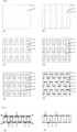
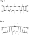
- Fig. 3 and 4 demonstrate that curved surfaces are also possible by appropriate choice of rovings.
- Carbon rovings are positioned on a cotton fabric as a carrier material using the soutache technique in accordance with the technical specification. Yarns made of polypropylene fibers are used as positioning threads. After the embroidery is finished, the fabric is impregnated with a solution of aluminum chloride and tartaric acid and thermally treated at 180 °C. This chemically and thermally destroys the cellulose base material and can then be removed mechanically.
- the two-dimensional embroidery is then knitted with two-component epoxy resin, e.g. Sikadur 300, whereby an application of approx. 30% of the weight of carbon is to be achieved and brought into the required shape. To do this, the still malleable structure is stretched over a curved form that corresponds to the installation geometry in the concrete. The reinforcement is then hardened on the form. After the reinforcement has hardened, it can be inserted into the finished formwork and encased in concrete.
- Carbon rovings are positioned on a polyvinyl alcohol fleece as a carrier material using the soutache technique in accordance with the technical specification.
- Yarns made of polypropylene fibers are used as positioning threads.
- the fleece is released with hot water and dried. If it is dried at a higher temperature, e.g. 180 °C, the polypropylene threads can also be solidified.
- the two-dimensional embroidery is then knitted with two-component epoxy resin, e.g. Sikadur 300, whereby an application of approx. 30% of the dead weight of carbon is to be achieved and brought into the required shape.
- the still malleable structure is stretched over a curved form that corresponds to the installation geometry in the concrete.
- the reinforcement is then hardened on the form. After the reinforcement has hardened, it can be inserted into the finished formwork and encased in concrete.
- Carbon rovings are positioned on a polyvinyl alcohol fleece as a carrier material using the soutache technique in accordance with the technical specification.
- Yarns made of polypropylene fibers are used as positioning threads.
- the fleece is released with hot water and dried at a higher temperature, e.g. 180 °C, to solidify the polypropylene threads.
- the two-dimensional embroidery is then knitted with a small amount of two-component epoxy resin, e.g. Sikadur 300, whereby an application of approx. 10% of the weight of carbon is to be achieved and brought into the required shape.
- the still malleable structure is stretched over a curved form that corresponds to the installation geometry in the concrete.
- the reinforcement is then hardened on the form. After the reinforcement has hardened, it can be removed.
- the reinforcement is impregnated with a wet-curing epoxy resin, inserted and cast in concrete.
- the invention relates to embroidered flat or curved, two-dimensional or three-dimensional reinforcement structures. These consist of refined alkali- and corrosion-resistant, endless high-performance fibers as reinforcement and are used to absorb tensile forces in an alkaline, hardening matrix, such as concrete.
- a curved reinforcement structure is defined as a structure with one-dimensional or multi-dimensional curvature.
- a three-dimensional reinforcement structure is defined as a structure made up of at least two connected flat or curved reinforcement structures. The latter are kept at a distance by integrated, load-bearing connecting structures.
- the invention relates to the production of load-oriented embroidered structures, which are produced by embroidering functional material in several levels, by means of TFP construction (Tailored Fiber Placement) or Soutache construction, fixed to a carrier, which is subsequently thermally or chemically destroyed.
- TFP construction Trimed Fiber Placement
- Soutache construction Fixed to a carrier, which is subsequently thermally or chemically destroyed.
- the invention also relates to the knot design (embroidery knot, material and release process) of a reinforcement structure, the arrangement of the functional material, the manufacturing process of a three-dimensional reinforcement structure and the expansion options of additional functions in the embroidery process (integration of spacers for the formwork, integration of light and current-conducting materials, integration of fastening elements).
- the invention relates to refined high-performance fibers whose surface properties result in a force-fitting bond to the curing matrix.
- the prior art addresses various technical aspects in the field of the invention. Among other things, it is noticeable that highly efficient and load-oriented textile reinforcement structures for a wide and diverse application in construction, such as structural concrete construction, are not available or do not meet the requirements sufficiently.
- the invention is therefore based on the task of providing load-appropriate alkali and corrosion-resistant materials arranged in the direction of the main tensile stress in a two-dimensional or three-dimensional reinforcement structure for an alkaline hardening matrix, such as concrete.
- This invention serves as a replacement for the steel reinforcement of complicated, heavily stressed components and can be used in many areas of construction, such as prefabricated construction, civil and structural engineering. It can also be used in combination with conventional reinforcement materials (slack steel, prestressing steel, basalt or carbon rods, etc.) to supplement the reinforcement of a concrete component and/or integrate additional functions (sensors) into the component.
- conventional reinforcement materials slack steel, prestressing steel, basalt or carbon rods, etc.
Landscapes
- Engineering & Computer Science (AREA)
- Architecture (AREA)
- Mechanical Engineering (AREA)
- Civil Engineering (AREA)
- Structural Engineering (AREA)
- Textile Engineering (AREA)
- Chemical & Material Sciences (AREA)
- Composite Materials (AREA)
- Reinforcement Elements For Buildings (AREA)
Applications Claiming Priority (2)
| Application Number | Priority Date | Filing Date | Title |
|---|---|---|---|
| ATA50799/2017A AT520486B1 (de) | 2017-09-20 | 2017-09-20 | Bewehrungsmaterial |
| PCT/AT2018/060221 WO2019056038A1 (de) | 2017-09-20 | 2018-09-20 | Bewehrungsmaterial |
Publications (3)
| Publication Number | Publication Date |
|---|---|
| EP3684985A1 EP3684985A1 (de) | 2020-07-29 |
| EP3684985C0 EP3684985C0 (de) | 2024-06-12 |
| EP3684985B1 true EP3684985B1 (de) | 2024-06-12 |
Family
ID=63722118
Family Applications (1)
| Application Number | Title | Priority Date | Filing Date |
|---|---|---|---|
| EP18781953.7A Active EP3684985B1 (de) | 2017-09-20 | 2018-09-20 | Bewehrungsmaterial |
Country Status (4)
| Country | Link |
|---|---|
| EP (1) | EP3684985B1 (pl) |
| AT (1) | AT520486B1 (pl) |
| PL (1) | PL3684985T3 (pl) |
| WO (1) | WO2019056038A1 (pl) |
Family Cites Families (5)
| Publication number | Priority date | Publication date | Assignee | Title |
|---|---|---|---|---|
| CA2046021C (en) * | 1990-07-05 | 2001-09-04 | John Frederick Porter | Reinforcement for wall systems |
| US6263629B1 (en) * | 1998-08-04 | 2001-07-24 | Clark Schwebel Tech-Fab Company | Structural reinforcement member and method of utilizing the same to reinforce a product |
| DE10061028A1 (de) * | 2000-12-08 | 2002-06-20 | Eads Deutschland Gmbh | Verfahren zum Herstellen von mehrschichtigen TFP-Preforms mittels schmelzbaren Fixierfäden |
| DE102005034395B4 (de) * | 2005-07-22 | 2008-04-10 | Airbus Deutschland Gmbh | Verfahren zur Herstellung von ein- oder mehrschichtigen Faservorformlingen im TFP-Verfahren |
| DE102014102861A1 (de) * | 2014-03-04 | 2015-09-10 | Technische Universität Dresden | Bewehrungsgitter für den Betonbau, Hochleistungsfilamentgarn für den Betonbau und Verfahren zu deren Herstellung |
-
2017
- 2017-09-20 AT ATA50799/2017A patent/AT520486B1/de active
-
2018
- 2018-09-20 EP EP18781953.7A patent/EP3684985B1/de active Active
- 2018-09-20 PL PL18781953.7T patent/PL3684985T3/pl unknown
- 2018-09-20 WO PCT/AT2018/060221 patent/WO2019056038A1/de not_active Ceased
Also Published As
| Publication number | Publication date |
|---|---|
| EP3684985C0 (de) | 2024-06-12 |
| EP3684985A1 (de) | 2020-07-29 |
| WO2019056038A1 (de) | 2019-03-28 |
| AT520486B1 (de) | 2020-11-15 |
| AT520486A1 (de) | 2019-04-15 |
| PL3684985T3 (pl) | 2024-10-21 |
Similar Documents
| Publication | Publication Date | Title |
|---|---|---|
| EP2666922B2 (de) | Textilbewehrtes Betonbauelement | |
| EP2941515B1 (de) | Fassadenbekleidungselement mit textilbewehrung und haltern und verfahren zu dessen erzeugung | |
| EP2758228B1 (de) | Faserhalbzeug, faser-verbundwerkstoff und verfahren zu deren herstellung | |
| DE102010042128A1 (de) | Strukturbauteil, Luft- oder Raumfahrzeug sowie Verfahren | |
| EP2839089A1 (de) | Bauelement und verfahren zur herstellung eines bauelements | |
| EP3245349B1 (de) | Bewehrungsstab aus filamentverbund und verfahren zu dessen herstellung | |
| WO2019243001A1 (de) | Faserverbundkörper sowie verfahren zur herstellung eines faserverbundkörpers | |
| DE102014013532A1 (de) | Honigwabenstruktur aus einem vlies aus rezyklierten kohlenstofffasern | |
| DE102017102366A1 (de) | Endverankerung von textilen Flächengebilden | |
| EP3114288B1 (de) | Bewehrungsgitter für den betonbau | |
| EP3318689B1 (de) | Bewehrungsgitterelement, baukörper mit einem solchen bewehrungsgitterelement sowie verfahren zur herstellung eines bewehrungsgitterelements | |
| EP3684985B1 (de) | Bewehrungsmaterial | |
| EP3162546B1 (de) | Zugelement aus faserverstärktem kunststoff und verfahren | |
| EP3460114B1 (de) | Verzweigungsknoten zum gebäudebau sowie verfahren zur herstellung des verzweigungsknotens zum gebäudebau | |
| DE102014105795B4 (de) | Textilbetonteil und Verfahren zu dessen Herstellung | |
| EP3705657B1 (de) | Textile bewehrungsstruktur für ein bauteil, herstellungsverfahren für eine bewehrungsstruktur, bauteil und halbfertigteil | |
| DE102016007464A1 (de) | Verstärkungsstreifen für ein rohrförmiges bauteil aus verbundmaterial | |
| EP2047046B1 (de) | Verstärkungselement, verfahren zur herstellung eines derartigen verstärkungselementes und bauteil, ausgestattet mit einem verstärkungselement | |
| DE102011107512A1 (de) | Duktile CFK-Struktur | |
| EP3552807B1 (de) | Faserverbundbauteil, hybridbauteil und verfahren zum herstellen eines faserverbundbauteils | |
| DE2119863A1 (en) | Lightweight building panel prodn - with deformed reinforcing core | |
| DE102015102437A1 (de) | Verfahren zur Herstellung einer Verstärkung für Flanschstrukturen aus Faserverbundwerkstoff | |
| WO2019161969A1 (de) | Fadenstruktur | |
| DE102015013775A1 (de) | Verfahren zum Herstellen eines Hybridbauteils | |
| DE202012001724U1 (de) | Leichtbauelement aus einem textilen Gewirk |
Legal Events
| Date | Code | Title | Description |
|---|---|---|---|
| STAA | Information on the status of an ep patent application or granted ep patent |
Free format text: STATUS: UNKNOWN |
|
| STAA | Information on the status of an ep patent application or granted ep patent |
Free format text: STATUS: THE INTERNATIONAL PUBLICATION HAS BEEN MADE |
|
| PUAI | Public reference made under article 153(3) epc to a published international application that has entered the european phase |
Free format text: ORIGINAL CODE: 0009012 |
|
| STAA | Information on the status of an ep patent application or granted ep patent |
Free format text: STATUS: REQUEST FOR EXAMINATION WAS MADE |
|
| 17P | Request for examination filed |
Effective date: 20200410 |
|
| AK | Designated contracting states |
Kind code of ref document: A1 Designated state(s): AL AT BE BG CH CY CZ DE DK EE ES FI FR GB GR HR HU IE IS IT LI LT LU LV MC MK MT NL NO PL PT RO RS SE SI SK SM TR |
|
| AX | Request for extension of the european patent |
Extension state: BA ME |
|
| DAV | Request for validation of the european patent (deleted) | ||
| DAX | Request for extension of the european patent (deleted) | ||
| RAP1 | Party data changed (applicant data changed or rights of an application transferred) |
Owner name: LOHNVEREDELUNG FUSSENEGGER & GRABHER GMBH |
|
| GRAP | Despatch of communication of intention to grant a patent |
Free format text: ORIGINAL CODE: EPIDOSNIGR1 |
|
| STAA | Information on the status of an ep patent application or granted ep patent |
Free format text: STATUS: GRANT OF PATENT IS INTENDED |
|
| INTG | Intention to grant announced |
Effective date: 20240207 |
|
| GRAS | Grant fee paid |
Free format text: ORIGINAL CODE: EPIDOSNIGR3 |
|
| GRAA | (expected) grant |
Free format text: ORIGINAL CODE: 0009210 |
|
| STAA | Information on the status of an ep patent application or granted ep patent |
Free format text: STATUS: THE PATENT HAS BEEN GRANTED |
|
| AK | Designated contracting states |
Kind code of ref document: B1 Designated state(s): AL AT BE BG CH CY CZ DE DK EE ES FI FR GB GR HR HU IE IS IT LI LT LU LV MC MK MT NL NO PL PT RO RS SE SI SK SM TR |
|
| REG | Reference to a national code |
Ref country code: GB Ref legal event code: FG4D Free format text: NOT ENGLISH |
|
| REG | Reference to a national code |
Ref country code: CH Ref legal event code: EP |
|
| REG | Reference to a national code |
Ref country code: IE Ref legal event code: FG4D Free format text: LANGUAGE OF EP DOCUMENT: GERMAN |
|
| REG | Reference to a national code |
Ref country code: DE Ref legal event code: R096 Ref document number: 502018014732 Country of ref document: DE |
|
| U01 | Request for unitary effect filed |
Effective date: 20240701 |
|
| U07 | Unitary effect registered |
Designated state(s): AT BE BG DE DK EE FI FR IT LT LU LV MT NL PT RO SE SI Effective date: 20240902 |
|
| PG25 | Lapsed in a contracting state [announced via postgrant information from national office to epo] |
Ref country code: HR Free format text: LAPSE BECAUSE OF FAILURE TO SUBMIT A TRANSLATION OF THE DESCRIPTION OR TO PAY THE FEE WITHIN THE PRESCRIBED TIME-LIMIT Effective date: 20240612 |
|
| PG25 | Lapsed in a contracting state [announced via postgrant information from national office to epo] |
Ref country code: GR Free format text: LAPSE BECAUSE OF FAILURE TO SUBMIT A TRANSLATION OF THE DESCRIPTION OR TO PAY THE FEE WITHIN THE PRESCRIBED TIME-LIMIT Effective date: 20240913 |
|
| PG25 | Lapsed in a contracting state [announced via postgrant information from national office to epo] |
Ref country code: ES Free format text: LAPSE BECAUSE OF FAILURE TO SUBMIT A TRANSLATION OF THE DESCRIPTION OR TO PAY THE FEE WITHIN THE PRESCRIBED TIME-LIMIT Effective date: 20240612 |
|
| REG | Reference to a national code |
Ref country code: SK Ref legal event code: T3 Ref document number: E 44850 Country of ref document: SK |
|
| U20 | Renewal fee for the european patent with unitary effect paid |
Year of fee payment: 7 Effective date: 20240926 |
|
| PG25 | Lapsed in a contracting state [announced via postgrant information from national office to epo] |
Ref country code: HR Free format text: LAPSE BECAUSE OF FAILURE TO SUBMIT A TRANSLATION OF THE DESCRIPTION OR TO PAY THE FEE WITHIN THE PRESCRIBED TIME-LIMIT Effective date: 20240612 Ref country code: GR Free format text: LAPSE BECAUSE OF FAILURE TO SUBMIT A TRANSLATION OF THE DESCRIPTION OR TO PAY THE FEE WITHIN THE PRESCRIBED TIME-LIMIT Effective date: 20240913 Ref country code: ES Free format text: LAPSE BECAUSE OF FAILURE TO SUBMIT A TRANSLATION OF THE DESCRIPTION OR TO PAY THE FEE WITHIN THE PRESCRIBED TIME-LIMIT Effective date: 20240612 Ref country code: RS Free format text: LAPSE BECAUSE OF FAILURE TO SUBMIT A TRANSLATION OF THE DESCRIPTION OR TO PAY THE FEE WITHIN THE PRESCRIBED TIME-LIMIT Effective date: 20240912 |
|
| PG25 | Lapsed in a contracting state [announced via postgrant information from national office to epo] |
Ref country code: IS Free format text: LAPSE BECAUSE OF FAILURE TO SUBMIT A TRANSLATION OF THE DESCRIPTION OR TO PAY THE FEE WITHIN THE PRESCRIBED TIME-LIMIT Effective date: 20241012 |
|
| PG25 | Lapsed in a contracting state [announced via postgrant information from national office to epo] |
Ref country code: SM Free format text: LAPSE BECAUSE OF FAILURE TO SUBMIT A TRANSLATION OF THE DESCRIPTION OR TO PAY THE FEE WITHIN THE PRESCRIBED TIME-LIMIT Effective date: 20240612 |
|
| PG25 | Lapsed in a contracting state [announced via postgrant information from national office to epo] |
Ref country code: SM Free format text: LAPSE BECAUSE OF FAILURE TO SUBMIT A TRANSLATION OF THE DESCRIPTION OR TO PAY THE FEE WITHIN THE PRESCRIBED TIME-LIMIT Effective date: 20240612 Ref country code: IS Free format text: LAPSE BECAUSE OF FAILURE TO SUBMIT A TRANSLATION OF THE DESCRIPTION OR TO PAY THE FEE WITHIN THE PRESCRIBED TIME-LIMIT Effective date: 20241012 |
|
| PLBE | No opposition filed within time limit |
Free format text: ORIGINAL CODE: 0009261 |
|
| STAA | Information on the status of an ep patent application or granted ep patent |
Free format text: STATUS: NO OPPOSITION FILED WITHIN TIME LIMIT |
|
| PG25 | Lapsed in a contracting state [announced via postgrant information from national office to epo] |
Ref country code: MC Free format text: LAPSE BECAUSE OF FAILURE TO SUBMIT A TRANSLATION OF THE DESCRIPTION OR TO PAY THE FEE WITHIN THE PRESCRIBED TIME-LIMIT Effective date: 20240612 |
|
| 26N | No opposition filed |
Effective date: 20250313 |
|
| PG25 | Lapsed in a contracting state [announced via postgrant information from national office to epo] |
Ref country code: IE Free format text: LAPSE BECAUSE OF NON-PAYMENT OF DUE FEES Effective date: 20240920 |
|
| REG | Reference to a national code |
Ref country code: CH Ref legal event code: U11 Free format text: ST27 STATUS EVENT CODE: U-0-0-U10-U11 (AS PROVIDED BY THE NATIONAL OFFICE) Effective date: 20251001 |
|
| PGFP | Annual fee paid to national office [announced via postgrant information from national office to epo] |
Ref country code: NO Payment date: 20250924 Year of fee payment: 8 |
|
| PGFP | Annual fee paid to national office [announced via postgrant information from national office to epo] |
Ref country code: GB Payment date: 20250918 Year of fee payment: 8 |
|
| U20 | Renewal fee for the european patent with unitary effect paid |
Year of fee payment: 8 Effective date: 20250925 |
|
| PGFP | Annual fee paid to national office [announced via postgrant information from national office to epo] |
Ref country code: TR Payment date: 20251016 Year of fee payment: 8 |
|
| PGFP | Annual fee paid to national office [announced via postgrant information from national office to epo] |
Ref country code: CH Payment date: 20251001 Year of fee payment: 8 |
|
| PGFP | Annual fee paid to national office [announced via postgrant information from national office to epo] |
Ref country code: CZ Payment date: 20251007 Year of fee payment: 8 |
|
| PGFP | Annual fee paid to national office [announced via postgrant information from national office to epo] |
Ref country code: PL Payment date: 20251010 Year of fee payment: 8 |
|
| PGFP | Annual fee paid to national office [announced via postgrant information from national office to epo] |
Ref country code: SK Payment date: 20251013 Year of fee payment: 8 |
|
| PG25 | Lapsed in a contracting state [announced via postgrant information from national office to epo] |
Ref country code: CY Free format text: LAPSE BECAUSE OF FAILURE TO SUBMIT A TRANSLATION OF THE DESCRIPTION OR TO PAY THE FEE WITHIN THE PRESCRIBED TIME-LIMIT; INVALID AB INITIO Effective date: 20180920 |
|
| PG25 | Lapsed in a contracting state [announced via postgrant information from national office to epo] |
Ref country code: HU Free format text: LAPSE BECAUSE OF FAILURE TO SUBMIT A TRANSLATION OF THE DESCRIPTION OR TO PAY THE FEE WITHIN THE PRESCRIBED TIME-LIMIT; INVALID AB INITIO Effective date: 20180920 |