EP3684704B1 - Spout seal for a container - Google Patents
Spout seal for a container Download PDFInfo
- Publication number
- EP3684704B1 EP3684704B1 EP18859017.8A EP18859017A EP3684704B1 EP 3684704 B1 EP3684704 B1 EP 3684704B1 EP 18859017 A EP18859017 A EP 18859017A EP 3684704 B1 EP3684704 B1 EP 3684704B1
- Authority
- EP
- European Patent Office
- Prior art keywords
- seal
- spout
- container
- annular
- annular end
- Prior art date
- Legal status (The legal status is an assumption and is not a legal conclusion. Google has not performed a legal analysis and makes no representation as to the accuracy of the status listed.)
- Active
Links
- 230000009969 flowable effect Effects 0.000 claims description 10
- 238000000034 method Methods 0.000 claims description 5
- 238000007789 sealing Methods 0.000 claims description 5
- 239000000126 substance Substances 0.000 claims 6
- 239000012530 fluid Substances 0.000 description 12
- 239000000463 material Substances 0.000 description 7
- 230000035622 drinking Effects 0.000 description 5
- 239000007788 liquid Substances 0.000 description 3
- -1 but not limited to Substances 0.000 description 2
- 238000010276 construction Methods 0.000 description 2
- 238000001746 injection moulding Methods 0.000 description 2
- 229920002725 thermoplastic elastomer Polymers 0.000 description 2
- XLYOFNOQVPJJNP-UHFFFAOYSA-N water Substances O XLYOFNOQVPJJNP-UHFFFAOYSA-N 0.000 description 2
- 229920002943 EPDM rubber Polymers 0.000 description 1
- 239000004743 Polypropylene Substances 0.000 description 1
- XUIMIQQOPSSXEZ-UHFFFAOYSA-N Silicon Chemical compound [Si] XUIMIQQOPSSXEZ-UHFFFAOYSA-N 0.000 description 1
- 230000015556 catabolic process Effects 0.000 description 1
- 229920001577 copolymer Polymers 0.000 description 1
- 238000006731 degradation reaction Methods 0.000 description 1
- 230000009977 dual effect Effects 0.000 description 1
- 230000000694 effects Effects 0.000 description 1
- 239000008187 granular material Substances 0.000 description 1
- 238000012986 modification Methods 0.000 description 1
- 230000004048 modification Effects 0.000 description 1
- 230000037361 pathway Effects 0.000 description 1
- 229920000642 polymer Polymers 0.000 description 1
- 229920001155 polypropylene Polymers 0.000 description 1
- 230000000750 progressive effect Effects 0.000 description 1
- 150000003839 salts Chemical class 0.000 description 1
- 229910052710 silicon Inorganic materials 0.000 description 1
- 239000010703 silicon Substances 0.000 description 1
- 229920002379 silicone rubber Polymers 0.000 description 1
- 235000013599 spices Nutrition 0.000 description 1
- 239000003381 stabilizer Substances 0.000 description 1
- 229920001169 thermoplastic Polymers 0.000 description 1
- 239000004416 thermosoftening plastic Substances 0.000 description 1
Images


Classifications
-
- B—PERFORMING OPERATIONS; TRANSPORTING
- B65—CONVEYING; PACKING; STORING; HANDLING THIN OR FILAMENTARY MATERIAL
- B65D—CONTAINERS FOR STORAGE OR TRANSPORT OF ARTICLES OR MATERIALS, e.g. BAGS, BARRELS, BOTTLES, BOXES, CANS, CARTONS, CRATES, DRUMS, JARS, TANKS, HOPPERS, FORWARDING CONTAINERS; ACCESSORIES, CLOSURES, OR FITTINGS THEREFOR; PACKAGING ELEMENTS; PACKAGES
- B65D47/00—Closures with filling and discharging, or with discharging, devices
- B65D47/04—Closures with discharging devices other than pumps
- B65D47/06—Closures with discharging devices other than pumps with pouring spouts or tubes; with discharge nozzles or passages
- B65D47/061—Closures with discharging devices other than pumps with pouring spouts or tubes; with discharge nozzles or passages with telescopic, retractable or reversible spouts, tubes or nozzles
- B65D47/063—Closures with discharging devices other than pumps with pouring spouts or tubes; with discharge nozzles or passages with telescopic, retractable or reversible spouts, tubes or nozzles with flexible parts
-
- B—PERFORMING OPERATIONS; TRANSPORTING
- B65—CONVEYING; PACKING; STORING; HANDLING THIN OR FILAMENTARY MATERIAL
- B65D—CONTAINERS FOR STORAGE OR TRANSPORT OF ARTICLES OR MATERIALS, e.g. BAGS, BARRELS, BOTTLES, BOXES, CANS, CARTONS, CRATES, DRUMS, JARS, TANKS, HOPPERS, FORWARDING CONTAINERS; ACCESSORIES, CLOSURES, OR FITTINGS THEREFOR; PACKAGING ELEMENTS; PACKAGES
- B65D47/00—Closures with filling and discharging, or with discharging, devices
- B65D47/04—Closures with discharging devices other than pumps
- B65D47/20—Closures with discharging devices other than pumps comprising hand-operated members for controlling discharge
- B65D47/26—Closures with discharging devices other than pumps comprising hand-operated members for controlling discharge with slide valves, i.e. valves that open and close a passageway by sliding over a port, e.g. formed with slidable spouts
- B65D47/28—Closures with discharging devices other than pumps comprising hand-operated members for controlling discharge with slide valves, i.e. valves that open and close a passageway by sliding over a port, e.g. formed with slidable spouts having linear movement
- B65D47/283—Closures with discharging devices other than pumps comprising hand-operated members for controlling discharge with slide valves, i.e. valves that open and close a passageway by sliding over a port, e.g. formed with slidable spouts having linear movement between tubular parts
Definitions
- the present disclosure relates to a container including a retractable spout, and a seal for the retractable spout of the container, and to a method of sealing a container with a movable spout.
- dispensing containers there are various types of dispensing containers currently on the market that include a sealable spout.
- a popular use of such dispensing containers is for drink bottles configured to hold water or other fluids.
- a simply type of spout used for drinking bottles has a push-pull configuration, wherein when the spout is physically pulled into an extended arrangement a passageway is opened to allow movement of the fluid therethrough.
- a push-pull configuration wherein when the spout is physically pulled into an extended arrangement a passageway is opened to allow movement of the fluid therethrough.
- spout is disclosed in US Patent 8701906 to Blast Max LLC. , that has a push-pull, flow-through drinking spout including upper and lower seals.
- WO 2016/044890 discloses a container according to the preamble of claim 1.
- bite-actuated mouthpieces however have a tendency to suffer from mechanical damage during use, which may lead to leakage or failure of the seal.
- a container including a retractable spout, and a seal for the retractable spout of the container, as claimed in claim 1.
- the intermediate portion of the tubular body is configured to move inwardly of the first annular end, such that the intermediate portion is inverted or folded over itself as the spout is moved from said retracted position into the extended position. In a sense the tubular body rolls or folds over itself as the spout moves into the retracted position.
- the intermediate portion may be of a uniform thickness or may have a plurality of annular grooves or ridges therearound.
- the first annular end is fixedly held by the internal frame, wherein the spout is able to at least partly retract through the second aperture when in said retracted position, and extend at least partly through the first aperture when in said extended position.
- the second aperture of the internal frame is dimensioned to allow passage of at least a part of the intermediate portion therethrough and may be dimensioned to allow passage of the second annular end, when the spout is being moved between the retracted and extended positions.
- the internal frame may include a plurality of depending legs, preferably three legs, which hold the platform in a spaced apart position inwardly of said opening.
- depending legs and platform are unitary in construction.
- the first end of the seal includes an outwardly projecting circumferential shoulder, wherein a downwardly open groove extends into or is formed by the shoulder, such that the groove extends generally circumferentially around the first end.
- the upper surface of the shoulder may also include an inner annular lip that extends therearound. The shoulder is configured to engage with the internal frame to thereby fixedly hold the first end thereto.
- the internal frame is formed by two separate members that are configured to cooperate to thereby hold or clamp the first end or shoulder of the seal therebetween.
- the internal frame may comprise an upper surface of a base member and an insert that may be connected to the lid base member using fixing means such as screws or may be configured to clip together or frictionally engage.
- the upper surface of the lid base member may include an annular shaped upstand that is configured to engage with the downwardly open groove of the seal, and the insert abuts an upper surface of the shoulder outwardly of the inner annular lip.
- the inner annular lip provides greater flexibility for the intermediate portion as it moves inwardly of the first annular end.
- the intermediate portion of the seal may be tapered inwardly toward the second annular end, at between 1 and 5 degrees, and preferably 2 degrees, wherein the tapered intermediate portion is configured to engage with a correspondingly shaped tapered portion of the spout to thereby assist with maintaining frictional engagement therebetween.
- the seal profile will be easier where the seal includes a taper.
- the spout preferably has a corresponding taper so that the seal remains supported at least partially therealong.
- the taper is not essential and furthermore a tapered seal could be used on a spout that does not include a corresponding taper.
- the seal may be constructed from thermoplastic elastomers (TPE) having a polypropylene base.
- TPE thermoplastic elastomers
- Other copolymers or polymer mixes with thermoplastic and elastomeric properties may also be used.
- Other materials that could be used include, but are not limited to, silicon rubber, EPDM rubber, silicon or any material with suitable elastomeric properties.
- UV stabilisers may be added to the material forming the seal to inhibit degradation due to the effects of sunlight.
- the seal is unitary in construction and may be formed by injection moulding.
- seal 10 for a spout 12 of a container 14 demonstrating by way of examples, arrangements in which the principles of the present invention may be employed.
- the seal 10 includes a first annular end 16 that is configured to be fixedly held circumferentially adjacent an opening 18 in the container 14.
- the seal 10 further includes a second annular end 20 for engagement with and configured to extend downwardly from an inner or lower end 22 of said spout 12, as illustrated in Figure 3a .
- An intermediate portion 24 of the seal 10 is tubular.
- the first annular end 16 includes an outwardly projecting circumferential shoulder 26, as illustrated in Figure 2 .
- the circumferential shoulder 26 includes a downwardly open groove 28 that extends thereinto or is at least formed by the shoulder 26, such that the groove 28 extends generally circumferentially around the first annular end 16.
- the upper surface of the shoulder 26 includes an annular lip 30 that extends therearound.
- the second annular end 20 includes two spaced apart thickened portions 32, 34, which assist in the engagement with the lower end 22 of the spout 12 and inhibits the seal 10 from detaching therefrom.
- the thickened portions 32, 34 also assist with sealing when abutting the platform 56.
- the second annular end 20 may not include thickened portions, such that it is of uniform thickness, whereby in such a case engagement would rely primarily upon frictional engagement to inhibit detachment from the spout 12.
- FIGS 3a and 3b illustrate the attachment of the seal 10 to one embodiment of the container 14 having a movable spout 12.
- the container 14 includes a base 36 defining a chamber 38 for holding a flowable material 40, in the present embodiment being a liquid.
- a lid assembly 42 is attached to the base 36 by way of cooperating screw threads 44, 46.
- the lid assembly 42 includes an internal frame 48 having aperture 50 and a top cover 52 also including an aperture 54.
- the apertures 50 and 54 coaxially align to thereby define the opening 18 in the container 14.
- the internal frame 48 further include a depending leg or legs 56 that are configured to hold the platform 56 spaced apart from the opening 18.
- first annular end 16 is attached to or fixedly held by the internal frame 48.
- the second annular end 20 is configured to engage with and extend downwardly from the inner end 22 of said spout 12.
- the spout 12 is able to, at least partly, retract through aperture 50 when in the retracted position, whereby the second annular end 20 bears against the platform 58 to thereby inhibit movement of the liquid out through the spout 12.
- the first and second annular ends 16, 20 remain fixed to frame 48 or spout 12 respectively.
- the spout 12 extends at least partly out through aperture 54 in the top cover 52 when in the extended position and the fluid 38 is able to move out through the opening 18, as indicated by the broken arrow in Figure 3b , when the container 14 is tilted.
- the flow of fluid 38 is inhibited or stopped because the second annular end 20 bears against the bearing surface of the platform 58.
- Figure 4 illustrates an exploded view of one possible embodiment of the lid assembly 42. Similar configurations of movable spouts have been previously disclosed by the present Applicant in International Applications, PCT/AU2015/050567 entitled Bottle Lid Assembly with Retractable Spout, and PCT/AU2018/050293 entitled Apparatus and Method for Measuring Fluid Consumption. Some of the details of the movable spout and operation thereof, will not be repeated to not obscure the present invention.
- the top cover 52 of the present embodiment can be fixed relative to a lid base member 60 by way of fixing members 62.
- the top cover 52 includes the aperture 54 that can be closed by a pivotable flap 64.
- the spout 12 includes a fluid pathway 66, mouthpiece 68, inner end 22 and projection 70 having fingers 72a, 72b, 72c that extend sidewardly from an opposite side of the spout 12.
- the projection 70 includes apertures 74 that are configured to engage respective spring posts 76.
- the lid assembly 42 further includes a generally cylindrical main body 78, that is able to rotated relative to the lid base member 60 and includes inwardly projecting flanges 80a, 80b, 80c in the form of a flight or three start threads.
- the fingers 72a, 72b, 72c abut an underside of the inwardly projecting flanges 80a, 80b, 80c and act as a guide when the spout 16 is moving between retracted and extended positions, as disclosed in PCT/AU2015/050567 .
- the lid base member 60 includes three depending legs 56a, 56b and 56c that support or hold the platform 58 spaced apart from the opening 18.
- the lid assembly 42 further includes a latch mechanism 82 that inhibits rotation of the main body 78 against the influence of biasing springs (not shown) that engage respective spring posts 76.
- the lid assembly 42 also includes an insert 84 having apertures 86, 90 shaped to slid over spring posts 76 and permit passage of the spout 12 therethrough.
- the insert 84 is attached to the lid base member 60 by way of screws (not shown) that engage though respective apertures.
- Three legs 92 extend upwardly and are configured to engage a plate 94 that is attached over spring posts 76 that passes though apertures 96.
- the plate 94 similarly includes an aperture 98 that permits passage of the spout 12 therethrough.
- Figures 5a to 5c illustrate the operation of the lid assembly 42 of the present embodiment.
- Figure 5a illustrates the spout 12 in a retracted position within the lid assembly 42, wherein the pivotable flap 64 covers or closes aperture 54.
- the releasable latch mechanism 82 comprises a button 100 and locking device 102, wherein rotation of the main body 78 is inhibited.
- a user releases the locking device 102 and depresses the button 100 to trigger the spout 16 to move under the influence of the biasing springs from the retracted position, as shown in Figure 5a , into the extended position, as shown in Figure 5c .
- This is accomplished by rotation of the main body 78 around the longitudinal axis 88, as indicated by the arrow in Figure 5b .
- the pivotable flap 64 clears the aperture 54 to enable the spout 12 to move upwardly therethrough, from the retracted position to the extended position.
- the user can utilise the spout 16 to access the fluid 40 contained within the bottle 14.
- the user When the user has finished drinking or pouring fluid from the spout 12, they can grasp the outer surface of the main body 78 and manually rotate it against the bias of the biasing springs into the closed position, wherein the spout 12 is retracted and the pivotable flap 64 closes opening 54.
- the latch mechanism 82 then maintains the spout 12 in the retracted position against the bias until the button 100 is actuated by a user.
- the base member 60 includes an upstand 104 that has an annular shape and is configured to engage with the downwardly open groove 28 of the seal 10.
- the insert 84 abuts an upper surface of the shoulder 26 outwardly of the lip 30.
- the inner or lower end 22 of the spout 12 includes a slit 106 extending circumferentially around the spout 22 that is configured to engage with thickened portion 32 of the seal 10, as shown in Figures 6 , 9 and 12 .
- the slit 106 is configured to assist in maintaining the position of the second annular end 20 on the inner end 22 of the spout 12. The reader should however appreciate that according to claim 1, the inner end 22 frictionally engages the second annular end 20.
- Figures 6 to 8 illustrate the arrangement of the seal 10 when the spout 12 is in a retracted positioned.
- the intermediate portion 24 is stretch downwardly over the outer surface of the spout 12 and the second end 20 is compressed against the platform 58. It should be appreciated by the reader that the intermediate portion 24 preferably conforms to the outer surface of the spout 12.
- FIGs 9 to 11 illustrate the arrangement of the seal 10 and spout 12 in an intermediate position 24 between the fully retracted and fully extended positions. As the spout 12 moves upwardly the intermediate portion 24 begins to invert or fold over itself as it moves inwardly through the first annular end 16. The reader should appreciate that the inner annular lip 30 provides greater flexibility for the intermediate portion 24 as it moves inwardly through the first annular end 16.
- the second annular end 20 is also now in an uncompressed arrangement, as can best be seen by comparing Figures 6 and 9 or Figures 8 and 11 .
- Figures 12 to 14 illustrate the arrangement of the seal 10 and spout 12 in a fully extended position.
- the second annular end 20 remains inwardly of the first annular end 16 with the intermediate position 24 completely folded over itself and extending upwardly through the aperture 86 of the insert 84.
- Figures 15 to 17 illustrate a simplified configuration of the lid assembly 42 and the progressive movement of the spout 12 from a retracted position, as illustrated in Figure 15 , through an intermediate position, as illustrated in Figure 16 , into an extended position, as illustrated in Figure 17 .
- the reader will appreciate that Figures 15 to 17 illustrate the movement of seal 10 at is inverts or folds over itself.
- Figure 18 illustrates a second embodiment of the seal 10 that has a tapered intermediate portion 24, such that it is configured to engage with a tapered portion 108 of the spout 12.
- the taper on the seal 10 of the present embodiment is 2 degrees and the tapered portion 108 of the spout 12 is correspondingly shaped to assist with maintaining fractional engagement.
- the second annular end 20 of the seal 10 in the present embodiment is of uniform thickness and does not include thickened portions. Therefore, the inner end 22 of the spout 12, shown in Figure 18 , does not include a slit 106 extending circumferentially around the spout 22, however the reader should appreciate that the end 22 may alternatively include an annular slit, as previously discussed, for retaining a part of the seal 10.
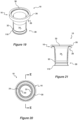
- Figures 19 to 21 show another embodiment of the seal 10 that includes a lower or second annular end 20 having a thickened portion 32 and a depending annular skirt 110, which bears against the platform 58 when the spout 12 is in the retracted position. As illustrated in Figure 21 , the skirt 110 is splayed towards a lower edge to assist in sealing against the platform 58.
- the thickened portion 32 is configured to engage overhang 112, illustrated in Figure 22 , that is located at the lower end 22 of said spout 12.
- Figure 22 further illustrates rollers 114a, 114b, 114c, that engage respective spigots 116 on fingers 72a, 72b, 72c.
- the rollers 114a, 114b, 114c engage an underside of the inwardly projecting flanges 80a, 80b, 80c to reduce friction and thereby assist in the movement of the spout 12 between retracted and extended positions, as described in PCT/AU2015/050567 .
- the present embodiment discloses a sealable container and method of use.
- Various fixing means and other components may be used to construct the lid assembly 14, which are not currently illustrated but which would be obvious to a person skilled in the art. Details of some of the fixing means other components or equivalent parts, and the operation of the moveable spout in general are detailed in International Applications PCT/AU2015/050567 and PCT/AU2018/050293 , both in the name of the present Application.
- a seal for a drinking vessel and a sealable container including a seal.
- the seal inhibits movement of the liquid or other flowable material out between the outer surface of the spout and the sides of the opening through which the spout is configured to extend. Furthermore, the seal inhibits movement of the flowable material out through the spout when in a retracted position.
- the invention provides a dual function seal for a movable spout.
Landscapes
- Engineering & Computer Science (AREA)
- Mechanical Engineering (AREA)
- Closures For Containers (AREA)
- Tubes (AREA)
Description
- The present disclosure relates to a container including a retractable spout, and a seal for the retractable spout of the container, and to a method of sealing a container with a movable spout.
- There are various types of dispensing containers currently on the market that include a sealable spout. A popular use of such dispensing containers is for drink bottles configured to hold water or other fluids.
- A simply type of spout used for drinking bottles has a push-pull configuration, wherein when the spout is physically pulled into an extended arrangement a passageway is opened to allow movement of the fluid therethrough. One example of such as spout is disclosed in
US Patent 8701906 to Blast Max LLC. , that has a push-pull, flow-through drinking spout including upper and lower seals. - Another drink bottle is disclosed in
US 20110198361 (Chen ), which teaches a bottle cap with a pivotal spout that is configured to be positioned at an obtuse angle for drinking and stored vertically in a crevice, flush against one side of a loop handle when not in use. These types of bottles primarily rely upon the misaligned of channels to inhibit the flow of the fluid therethrough and often include a flexible abutment surface or button seal. - Additionally ,
WO 2016/044890 discloses a container according to the preamble ofclaim 1. - All the above types of seals however tend to wear over time, which may result in leakage of the fluid.
- Other drink bottle manufactures use bite-actuated mouthpieces that allow passage of a fluid when a user bites onto the spout. One such spout is disclosed in
US 7533783 to Camelbak Products, LLC. , that teaches a drink bottle include a bite-actuated dispensing spout that is pivotally coupled to the cap of the drink bottle. - Such bite-actuated mouthpieces however have a tendency to suffer from mechanical damage during use, which may lead to leakage or failure of the seal.
- The present invention will be described with particular reference to a fluid, such as water, however the reader should appreciate that the seal could be used with respect to containers for holding any type of flowable material including, but not limited to, granular material, such as salt, spices or sugar.
- It is an object of the present invention to provide a seal for a retractable spout. It is another object of the present invention to overcome at least some of the aforementioned problems or at least provide the public with a useful alternative.
- It should be appreciated that any discussion of the prior art throughout the specification is included solely for the purpose of providing a context for the present invention and should in no way be considered as an admission that such prior art was widely known or formed part of the common general knowledge in the field as it existed before the priority date of the application.
- In one aspect of the invention, there is provided a container including a retractable spout, and a seal for the retractable spout of the container, as claimed in
claim 1. - The intermediate portion of the tubular body is configured to move inwardly of the first annular end, such that the intermediate portion is inverted or folded over itself as the spout is moved from said retracted position into the extended position. In a sense the tubular body rolls or folds over itself as the spout moves into the retracted position.
- The intermediate portion may be of a uniform thickness or may have a plurality of annular grooves or ridges therearound.
- In a preferred form, the first annular end is fixedly held by the internal frame, wherein the spout is able to at least partly retract through the second aperture when in said retracted position, and extend at least partly through the first aperture when in said extended position.
- The second aperture of the internal frame is dimensioned to allow passage of at least a part of the intermediate portion therethrough and may be dimensioned to allow passage of the second annular end, when the spout is being moved between the retracted and extended positions.
- The internal frame may include a plurality of depending legs, preferably three legs, which hold the platform in a spaced apart position inwardly of said opening. Preferably the internal frame, depending legs and platform are unitary in construction.
- In one form the first end of the seal includes an outwardly projecting circumferential shoulder, wherein a downwardly open groove extends into or is formed by the shoulder, such that the groove extends generally circumferentially around the first end. The upper surface of the shoulder may also include an inner annular lip that extends therearound. The shoulder is configured to engage with the internal frame to thereby fixedly hold the first end thereto.
- In one form, the internal frame is formed by two separate members that are configured to cooperate to thereby hold or clamp the first end or shoulder of the seal therebetween. The internal frame may comprise an upper surface of a base member and an insert that may be connected to the lid base member using fixing means such as screws or may be configured to clip together or frictionally engage. The upper surface of the lid base member may include an annular shaped upstand that is configured to engage with the downwardly open groove of the seal, and the insert abuts an upper surface of the shoulder outwardly of the inner annular lip.
- Preferably, the inner annular lip provides greater flexibility for the intermediate portion as it moves inwardly of the first annular end.
- In another form, the intermediate portion of the seal may be tapered inwardly toward the second annular end, at between 1 and 5 degrees, and preferably 2 degrees, wherein the tapered intermediate portion is configured to engage with a correspondingly shaped tapered portion of the spout to thereby assist with maintaining frictional engagement therebetween.
- It may be that injection moulding of the seal profile will be easier where the seal includes a taper. Where a tapered seal is used the spout preferably has a corresponding taper so that the seal remains supported at least partially therealong. However, the reader should appreciate that the taper is not essential and furthermore a tapered seal could be used on a spout that does not include a corresponding taper.
- The seal may be constructed from thermoplastic elastomers (TPE) having a polypropylene base. Other copolymers or polymer mixes with thermoplastic and elastomeric properties may also be used. Other materials that could be used include, but are not limited to, silicon rubber, EPDM rubber, silicon or any material with suitable elastomeric properties. UV stabilisers may be added to the material forming the seal to inhibit degradation due to the effects of sunlight.
- Preferably the seal is unitary in construction and may be formed by injection moulding.
- In another aspect of the invention there is provided a method of sealing a container having a movable spout, as claimed in
claim 14. - The accompanying drawings, which are incorporated in and constitute a part of this specification, illustrate an implementation of the invention and, together with the description and claims, serve to explain the advantages and principles of the invention. In the drawings,
- Figure 1
- is a perspective view of one embodiment of a seal of the present invention;
- Figure 2
- is a cross-sectional view through A-A of the seal of
Figure 1 ; - Figure 3a
- is a schematic view of the seal located within a bottle having a movable spout, illustrating the spout in a retracted position;
- Figure 3b
- is a schematic view of the seal and bottle of
Figure 3a , illustrating the spout in an extended position; - Figure 4
- is an exploded view of one possible embodiment of the bottle and movable spout;
- Figure 5a
- is a perspective view of the bottle of
Figure 4 , illustrating a pivotable flap covering the bottle opening thereby concealing the spout; - Figure 5b
- is a perspective view of the bottle of
Figure 5a illustrating the movement of the main body of the lid assembly and the pivotable flap; - Figure 5c
- is a perspective view of the bottle of
Figure 5b illustrating the spout in an extended position; - Figure 6
- is a partial cross-sectional view of the lid assembly of
Figure 5a , illustrating the position of the seal relative to the spout when the spout is in a retracted position; - Figure 7
- is a perspective view of the seal of
Figure 6 in an elongate arrangement; - Figure 8
- is a cross-sectional view of the seal through B-B of
Figure 7 ; - Figure 9
- is a partial cross-sectional view of the lid assembly of
Figure 5b , illustrating the position of the seal relative to the spout, when the spout is in a partially extended position; - Figure 10
- is a perspective view of the seal of
Figure 9 in a partially inverted arrangement; - Figure 11
- is a cross-sectional view of the seal through C-C of
Figure 10 ; - Figure 12
- is a partial cross-sectional view of the lid assembly of
Figure 5c , illustrating the position of the seal relative to the spout, when the spout is in a fully extended position; - Figure 13
- is a perspective view of the seal of
Figure 12 in an inverted arrangement; - Figure 14
- is a cross-sectional view of the seal through D-D of
Figure 13 ; - Figure 15
- is a schematic view of
Figure 6 , illustrating the seal bearing against the platform; - Figure 16
- is a schematic view of
Figure 9 , illustrating movement of the intermediate portion of the seal as it begins to fold over itself; - Figure 17
- is a schematic view of
Figure 12 , illustrating movement of the intermediate portion of the seal as it continues to fold over itself; - Figure 18
- is a perspective view of another embodiment of the seal which is tapered to engage with a tapered spout;
- Figure 19
- is a perspective view of a further embodiment of the seal;
- Figure 20
- is a top view of the seal of
Figure 19 ; - Figure 21
- is a cross-sectional view of the seal through E-E of
Figure 20 ; and - Figure 22
- is a perspective view of another embodiment of the spout.
- Similar reference characters indicate corresponding parts throughout the drawings. Dimensions of certain parts shown in the drawings may have been modified and/or exaggerated for the purposes of clarity or illustration.
- Referring to the drawings for a more detailed description, there is illustrated a
seal 10 for aspout 12 of acontainer 14, demonstrating by way of examples, arrangements in which the principles of the present invention may be employed. - As illustrated in
Figure 1 theseal 10 includes a firstannular end 16 that is configured to be fixedly held circumferentially adjacent anopening 18 in thecontainer 14. Theseal 10 further includes a secondannular end 20 for engagement with and configured to extend downwardly from an inner orlower end 22 of saidspout 12, as illustrated inFigure 3a . Anintermediate portion 24 of theseal 10 is tubular. - In the present embodiment, the first
annular end 16 includes an outwardly projectingcircumferential shoulder 26, as illustrated inFigure 2 . Thecircumferential shoulder 26 includes a downwardlyopen groove 28 that extends thereinto or is at least formed by theshoulder 26, such that thegroove 28 extends generally circumferentially around the firstannular end 16. The upper surface of theshoulder 26 includes anannular lip 30 that extends therearound. - In the present embodiment, the second
annular end 20 includes two spaced apart thickenedportions lower end 22 of thespout 12 and inhibits theseal 10 from detaching therefrom. The thickenedportions platform 56. The reader should however appreciate that the secondannular end 20 may not include thickened portions, such that it is of uniform thickness, whereby in such a case engagement would rely primarily upon frictional engagement to inhibit detachment from thespout 12. -
Figures 3a and 3b , illustrate the attachment of theseal 10 to one embodiment of thecontainer 14 having amovable spout 12. Thecontainer 14 includes a base 36 defining achamber 38 for holding aflowable material 40, in the present embodiment being a liquid. Alid assembly 42 is attached to thebase 36 by way of cooperatingscrew threads lid assembly 42 includes aninternal frame 48 havingaperture 50 and atop cover 52 also including anaperture 54. Theapertures opening 18 in thecontainer 14. - The
internal frame 48 further include a depending leg orlegs 56 that are configured to hold theplatform 56 spaced apart from theopening 18. - As illustrated in
Figure 3a , the firstannular end 16 is attached to or fixedly held by theinternal frame 48. The secondannular end 20 is configured to engage with and extend downwardly from theinner end 22 of saidspout 12. - As further illustrated in
Figure 3a , thespout 12 is able to, at least partly, retract throughaperture 50 when in the retracted position, whereby the secondannular end 20 bears against theplatform 58 to thereby inhibit movement of the liquid out through thespout 12. - When the
spout 12 is moved into the extended position, as illustrated inFigure 3b , the first and second annular ends 16, 20 remain fixed to frame 48 or spout 12 respectively. Thespout 12 extends at least partly out throughaperture 54 in thetop cover 52 when in the extended position and the fluid 38 is able to move out through theopening 18, as indicated by the broken arrow inFigure 3b , when thecontainer 14 is tilted. When thespout 12 is moved back into the fully retracted position the flow offluid 38 is inhibited or stopped because the secondannular end 20 bears against the bearing surface of theplatform 58. -
Figure 4 illustrates an exploded view of one possible embodiment of thelid assembly 42. Similar configurations of movable spouts have been previously disclosed by the present Applicant in International Applications,PCT/AU2015/050567 PCT/AU2018/050293 - The
top cover 52 of the present embodiment, can be fixed relative to alid base member 60 by way of fixingmembers 62. Thetop cover 52 includes theaperture 54 that can be closed by apivotable flap 64. - The
spout 12 includes afluid pathway 66,mouthpiece 68,inner end 22 andprojection 70 havingfingers spout 12. Theprojection 70 includes apertures 74 that are configured to engage respective spring posts 76. - The
lid assembly 42 further includes a generally cylindricalmain body 78, that is able to rotated relative to thelid base member 60 and includes inwardly projectingflanges fingers flanges spout 16 is moving between retracted and extended positions, as disclosed inPCT/AU2015/050567 - As illustrated in
Figure 4 , thelid base member 60 includes three dependinglegs platform 58 spaced apart from theopening 18. Thelid assembly 42 further includes alatch mechanism 82 that inhibits rotation of themain body 78 against the influence of biasing springs (not shown) that engage respective spring posts 76. - The
lid assembly 42 also includes aninsert 84 havingapertures spout 12 therethrough. Theinsert 84 is attached to thelid base member 60 by way of screws (not shown) that engage though respective apertures. Threelegs 92 extend upwardly and are configured to engage aplate 94 that is attached over spring posts 76 that passes thoughapertures 96. Theplate 94 similarly includes anaperture 98 that permits passage of thespout 12 therethrough. -
Figures 5a to 5c illustrate the operation of thelid assembly 42 of the present embodiment.Figure 5a illustrates thespout 12 in a retracted position within thelid assembly 42, wherein thepivotable flap 64 covers or closesaperture 54. Thereleasable latch mechanism 82 comprises abutton 100 and lockingdevice 102, wherein rotation of themain body 78 is inhibited. - To extend the spout 12 a user releases the
locking device 102 and depresses thebutton 100 to trigger thespout 16 to move under the influence of the biasing springs from the retracted position, as shown inFigure 5a , into the extended position, as shown inFigure 5c . This is accomplished by rotation of themain body 78 around thelongitudinal axis 88, as indicated by the arrow inFigure 5b . - As further illustrates in
Figure 5b , thepivotable flap 64 clears theaperture 54 to enable thespout 12 to move upwardly therethrough, from the retracted position to the extended position. In the extended position, as shown inFigure 5c , the user can utilise thespout 16 to access the fluid 40 contained within thebottle 14. - When the user has finished drinking or pouring fluid from the
spout 12, they can grasp the outer surface of themain body 78 and manually rotate it against the bias of the biasing springs into the closed position, wherein thespout 12 is retracted and thepivotable flap 64 closes opening 54. Thelatch mechanism 82 then maintains thespout 12 in the retracted position against the bias until thebutton 100 is actuated by a user. - As illustrated is
Figure 6 , thebase member 60 includes anupstand 104 that has an annular shape and is configured to engage with the downwardlyopen groove 28 of theseal 10. As further illustrated inFigure 6 , theinsert 84 abuts an upper surface of theshoulder 26 outwardly of thelip 30. In this way, the two separate members, thebase member 60 and theinsert 84, are configured to cooperate to thereby hold or clamp thefirst end 16 of theseal 10 therebetween as thespout 12 moves up and down through theopening 18. The inner orlower end 22 of thespout 12 includes aslit 106 extending circumferentially around thespout 22 that is configured to engage with thickenedportion 32 of theseal 10, as shown inFigures 6 ,9 and12 . Theslit 106 is configured to assist in maintaining the position of the secondannular end 20 on theinner end 22 of thespout 12. The reader should however appreciate that according toclaim 1, theinner end 22 frictionally engages the secondannular end 20. -
Figures 6 to 8 , illustrate the arrangement of theseal 10 when thespout 12 is in a retracted positioned. In this arrangement, theintermediate portion 24 is stretch downwardly over the outer surface of thespout 12 and thesecond end 20 is compressed against theplatform 58. It should be appreciated by the reader that theintermediate portion 24 preferably conforms to the outer surface of thespout 12. - When the
button 100 is pushed to release thelatch mechanism 82, the spout moves up the spring posts 92 as it begins to move into the extended position.Figures 9 to 11 illustrate the arrangement of theseal 10 andspout 12 in anintermediate position 24 between the fully retracted and fully extended positions. As thespout 12 moves upwardly theintermediate portion 24 begins to invert or fold over itself as it moves inwardly through the firstannular end 16. The reader should appreciate that the innerannular lip 30 provides greater flexibility for theintermediate portion 24 as it moves inwardly through the firstannular end 16. The secondannular end 20 is also now in an uncompressed arrangement, as can best be seen by comparingFigures 6 and9 orFigures 8 and11 . -
Figures 12 to 14 illustrate the arrangement of theseal 10 andspout 12 in a fully extended position. In the present embodiment, the secondannular end 20 remains inwardly of the firstannular end 16 with theintermediate position 24 completely folded over itself and extending upwardly through theaperture 86 of theinsert 84. -
Figures 15 to 17 illustrate a simplified configuration of thelid assembly 42 and the progressive movement of thespout 12 from a retracted position, as illustrated inFigure 15 , through an intermediate position, as illustrated inFigure 16 , into an extended position, as illustrated inFigure 17 . The reader will appreciate thatFigures 15 to 17 illustrate the movement ofseal 10 at is inverts or folds over itself. -
Figure 18 illustrates a second embodiment of theseal 10 that has a taperedintermediate portion 24, such that it is configured to engage with a taperedportion 108 of thespout 12. The taper on theseal 10 of the present embodiment, is 2 degrees and the taperedportion 108 of thespout 12 is correspondingly shaped to assist with maintaining fractional engagement. The secondannular end 20 of theseal 10 in the present embodiment is of uniform thickness and does not include thickened portions. Therefore, theinner end 22 of thespout 12, shown inFigure 18 , does not include aslit 106 extending circumferentially around thespout 22, however the reader should appreciate that theend 22 may alternatively include an annular slit, as previously discussed, for retaining a part of theseal 10. -
Figures 19 to 21 show another embodiment of theseal 10 that includes a lower or secondannular end 20 having a thickenedportion 32 and a dependingannular skirt 110, which bears against theplatform 58 when thespout 12 is in the retracted position. As illustrated inFigure 21 , theskirt 110 is splayed towards a lower edge to assist in sealing against theplatform 58. - The thickened
portion 32 is configured to engageoverhang 112, illustrated inFigure 22 , that is located at thelower end 22 of saidspout 12.Figure 22 further illustratesrollers respective spigots 116 onfingers rollers flanges spout 12 between retracted and extended positions, as described inPCT/AU2015/050567 - The reader will also appreciate that the present embodiment discloses a sealable container and method of use. Various fixing means and other components may be used to construct the
lid assembly 14, which are not currently illustrated but which would be obvious to a person skilled in the art. Details of some of the fixing means other components or equivalent parts, and the operation of the moveable spout in general are detailed in International ApplicationsPCT/AU2015/050567 PCT/AU2018/050293 - The skilled addressee will now appreciate the advantages of the illustrated embodiments over the prior art. There is provided a seal for a drinking vessel and a sealable container including a seal. The seal inhibits movement of the liquid or other flowable material out between the outer surface of the spout and the sides of the opening through which the spout is configured to extend. Furthermore, the seal inhibits movement of the flowable material out through the spout when in a retracted position. In this way, the invention provides a dual function seal for a movable spout.
- Various features of the invention have been particularly shown and described in connection with the exemplified embodiments of the invention, however it must be understood that these particular arrangements merely illustrate examples of the invention and it is not limited thereto. Accordingly, the invention can include various modifications, provided they fall within the scope of the claims.
Claims (14)
- A container (14) including a retractable spout (12), and a seal (10) for the retractable spout (12) of the container (14), the container (14) including a lid assembly (42) having a cover (52) with a first aperture (54) extending therethrough and an internal frame (48) having a second aperture (50) extending therethrough, the first and second apertures (54, 50) coaxially aligning to thereby delineate an opening (18) in the container (14), and an abutment surface comprising a platform (58) that is spaced apart from said opening (18), characterized in tha the seal (10) comprises:a flexible generally elongate tubular body; anda first annular end (16) being fixedly connected to said internal frame (48) adjacent the opening (18) in said container (14) through which said retractable spout (12) is configured to move, to thereby inhibit movement of a flowable substance out between an outer surface of said tubular body and an edge of said opening (18);wherein an intermediate portion (24) of the tubular body is configured to move inwardly of the first annular end (16), such that the intermediate portion (24) is inverted or folded over itself as the spout (12) is moved from a retracted position into an extended position;wherein the seal (10) comprises:
an opposite second annular end (20) frictionally engaged with and extending downwardly from a lower end of said retractable spout (12), whereby when the retractable spout (12) is in the retracted position the second annular end (20) of the seal (10) bears against said abutment surface of the container (14) to thereby inhibit movement of said flowable substance out through said retractable spout (12). - The container (14) and seal (10) in accordance with claim 1, wherein the second annular end (20) of the seal (10) includes at least one annular thickened portion (32, 34) configured to assist in the frictional engagement with the lower end of the retractable spout (12) to thereby inhibit the second annular end (20) separating therefrom.
- The container (14) and seal (10) in accordance with claim 1, wherein the second annular end (20) of the seal (10) includes a plurality of spaced apart annular thickened portions (32, 34), wherein the annular thickened portions (32, 34) assist in the frictional engagement with the lower end of the spout (12) to thereby inhibit the second annular end (20) separating therefrom.
- The container (14) and seal (10) in accordance with claim 2 or 3, wherein the lower end of the retractable spout (12) includes a slit (106) extending circumferentially around the retractable spout (12) and being configured to engage with a respective annular thickened portion (32, 34) or portions (32, 34) of the seal (10).
- The container (14) and seal (10) in accordance with claim 1, wherein the first annular end (16) is fixedly held by the internal frame (48), wherein the spout (12) is able to at least partly retract through the second aperture (50) when in said retracted position, and extend at least partly through the first aperture (54) when in said extended position.
- The container (14) and seal (10) in accordance with claim 5, wherein the second aperture (50) of the internal frame (48) is dimensioned to allow passage of at least a part of the intermediate portion (24) of the seal (10) therethrough and is dimensioned to allow passage of the second annular end (20), when the spout (12) is being moved between the retracted and extended positions.
- The container (14) and seal (10) in accordance with claim 6, wherein the internal frame (48) includes a plurality of depending legs (56), which hold the platform (48) in a spaced apart position inwardly of said opening (18).
- The container (14) and seal (10) in accordance with claim 1, wherein the first end (16) of the seal (10) includes an outwardly projecting circumferential shoulder (26), wherein a downwardly open groove (28) extends into or is formed by the shoulder (26), such that the groove (28) extends generally circumferentially around the first end (16).
- The container (14) and seal (10) in accordance with claim 8, wherein the upper surface of the shoulder (26) includes an inner annular lip (30) that extends therearound, the shoulder (26) being configured to engage with said internal frame (48) to thereby fixedly hold the first end (16) thereto.
- The container (14) and seal (10) in accordance with claim 8, wherein the internal frame (48) is formed by two separate members (60, 84) that are configured to cooperate to thereby hold or clamp the first end (16) or shoulder (26) of the seal (10) therebetween.
- The container (14) and seal (10) in accordance with claim 1, wherein the second annular end (20) includes an annular splayed skirt (110) which assists in engagement with the platform (58), when the spout (12) is in the retracted position.
- The container (14) and seal (10) in accordance with claim 1, wherein the intermediate portion (24) of the seal (10) is tapered between 1 and 5 degrees, or 2 degrees, whereby the tapered intermediate portion (24) is configured to engage with a correspondingly shaped tapered portion of the spout (12) to thereby assist with maintaining frictional engagement.
- The container (14) and seal (10) according to claim 1, the container (14) including a body (36) having a chamber (38) for holding a flowable substance, the lid assembly (42) being connectable to said body (36);
wherein the platform (58) is inward of said opening (18). - A method of sealing a container with a movable spout, including the steps of:providing a container (14) and seal (10) according to claim 1;inserting the spout (12) into the generally tubular seal (10), wherein the first annular end (16) and intermediate portion (24) circumferentially extend around the spout (12) and the second annular end (20) frictionally engages and extends downwardly from a lower end of the spout (12);fixing the first annular end (16) circumferentially to the internal frame (48) of said container (14) being located adjacent said opening (18) to thereby inhibit movement of the flowable substance out between an outer surface of the spout (12) and a circumferential edge of said opening (18); andcausing the spout (12), to be moved from:a. a retracted position, wherein the second annular end (20) bears against the platform (58) to thereby inhibit movement of the flowable substance through the spout (12);b. through a transitional position, wherein said intermediate portion (24) of the tubular seal (10) is inverted or folded over itself; andc. into an extended position, whereby the second annular end (20) is separated from the platform (58), wherein said flowable substance is able to flow out through the spout (12).
Applications Claiming Priority (2)
| Application Number | Priority Date | Filing Date | Title |
|---|---|---|---|
| AU2017903811A AU2017903811A0 (en) | 2017-09-19 | Spout seal for a container | |
| PCT/AU2018/051011 WO2019056056A1 (en) | 2017-09-19 | 2018-09-14 | Spout seal for a container |
Publications (4)
| Publication Number | Publication Date |
|---|---|
| EP3684704A1 EP3684704A1 (en) | 2020-07-29 |
| EP3684704A4 EP3684704A4 (en) | 2021-06-23 |
| EP3684704B1 true EP3684704B1 (en) | 2023-08-16 |
| EP3684704C0 EP3684704C0 (en) | 2023-08-16 |
Family
ID=65809442
Family Applications (1)
| Application Number | Title | Priority Date | Filing Date |
|---|---|---|---|
| EP18859017.8A Active EP3684704B1 (en) | 2017-09-19 | 2018-09-14 | Spout seal for a container |
Country Status (7)
| Country | Link |
|---|---|
| US (1) | US11254474B2 (en) |
| EP (1) | EP3684704B1 (en) |
| JP (1) | JP7234242B2 (en) |
| CN (1) | CN111132910B (en) |
| AU (1) | AU2018337071B2 (en) |
| CA (1) | CA3071591A1 (en) |
| WO (1) | WO2019056056A1 (en) |
Families Citing this family (2)
| Publication number | Priority date | Publication date | Assignee | Title |
|---|---|---|---|---|
| SG11201908665SA (en) * | 2017-03-29 | 2019-10-30 | Puratap Pty Ltd | Apparatus and method for measuring fluid consumption |
| CN115644660A (en) * | 2022-10-27 | 2023-01-31 | 宁波利时日用品有限公司 | Cup cover with telescopic drinking port and drinking cup |
Citations (1)
| Publication number | Priority date | Publication date | Assignee | Title |
|---|---|---|---|---|
| WO2016044890A1 (en) * | 2014-09-23 | 2016-03-31 | Puratap Pty Ltd | Bottle lid assembly with retractable spout |
Family Cites Families (15)
| Publication number | Priority date | Publication date | Assignee | Title |
|---|---|---|---|---|
| US3203665A (en) * | 1963-02-18 | 1965-08-31 | Rieke Metal Products Corp | Flex faucet |
| AU3034971A (en) * | 1971-06-23 | 1973-01-04 | Rieke Corporation | Nestable pouring spout with wall-supporting cap |
| DE4124245C1 (en) * | 1991-07-22 | 1992-11-12 | Heinrich Stolz Gmbh & Co Kg, 5908 Neunkirchen, De | |
| FR2715915B1 (en) * | 1994-02-10 | 1996-04-19 | Eric Guarnieri | Hermetic container with retractable neck. |
| JP3579172B2 (en) * | 1996-02-23 | 2004-10-20 | 株式会社吉野工業所 | Liquid storage container |
| GB2420777A (en) * | 2004-12-03 | 2006-06-07 | Henryk Dudzik | One-piece liquid dispensing closure |
| US7533783B2 (en) | 2005-04-11 | 2009-05-19 | Camelbak Products, Llc | Drink bottles with bite-actuated mouthpieces |
| FR2895732A1 (en) * | 2006-01-03 | 2007-07-06 | Seaquist General Plastics Soc | Cosmetic product e.g. cream, delivery device, has sealing structure disposed between slider and support, and forming seal connection portions with slider and support, where structure has sealing body which reunites connection portions |
| CN101734417B (en) * | 2008-11-13 | 2012-12-26 | 西奎斯特盖有限责任合作公司 | Bendable sealing element capable of penetrating through liner plate |
| US8701906B1 (en) | 2008-12-31 | 2014-04-22 | Blast Max Llc | Ingredient dispensing cap for mixing beverages with push-pull drinking spout |
| US20110198361A1 (en) | 2010-02-16 | 2011-08-18 | Elisa Chen | Flip straw bottle cap with loop handle storage spout |
| US9056699B2 (en) * | 2012-04-12 | 2015-06-16 | Funlpro Technology Llc | Pouring spout for container |
| UA117812C2 (en) * | 2012-09-10 | 2018-10-10 | Гуала Клоужес С.П.А. | Pourer with retractable spout |
| US20160318671A1 (en) * | 2015-05-01 | 2016-11-03 | Randy J. Sessions | Internal pull-out expandable contractible pour spout cap for liquid container openings |
| SG11201908665SA (en) | 2017-03-29 | 2019-10-30 | Puratap Pty Ltd | Apparatus and method for measuring fluid consumption |
-
2018
- 2018-09-14 US US16/648,416 patent/US11254474B2/en active Active
- 2018-09-14 AU AU2018337071A patent/AU2018337071B2/en active Active
- 2018-09-14 JP JP2020537264A patent/JP7234242B2/en active Active
- 2018-09-14 WO PCT/AU2018/051011 patent/WO2019056056A1/en active Search and Examination
- 2018-09-14 CA CA3071591A patent/CA3071591A1/en active Pending
- 2018-09-14 EP EP18859017.8A patent/EP3684704B1/en active Active
- 2018-09-14 CN CN201880060801.3A patent/CN111132910B/en active Active
Patent Citations (1)
| Publication number | Priority date | Publication date | Assignee | Title |
|---|---|---|---|---|
| WO2016044890A1 (en) * | 2014-09-23 | 2016-03-31 | Puratap Pty Ltd | Bottle lid assembly with retractable spout |
Also Published As
| Publication number | Publication date |
|---|---|
| AU2018337071B2 (en) | 2022-09-15 |
| CN111132910A (en) | 2020-05-08 |
| CA3071591A1 (en) | 2019-03-28 |
| JP2020534223A (en) | 2020-11-26 |
| US11254474B2 (en) | 2022-02-22 |
| EP3684704A1 (en) | 2020-07-29 |
| US20210362917A1 (en) | 2021-11-25 |
| WO2019056056A1 (en) | 2019-03-28 |
| CN111132910B (en) | 2022-05-31 |
| NZ762926A (en) | 2023-09-29 |
| EP3684704C0 (en) | 2023-08-16 |
| AU2018337071A1 (en) | 2020-04-16 |
| JP7234242B2 (en) | 2023-03-07 |
| EP3684704A4 (en) | 2021-06-23 |
Similar Documents
| Publication | Publication Date | Title |
|---|---|---|
| AU2008311561B2 (en) | Container with anti-loss and anti-idle-rotation cap | |
| KR100807212B1 (en) | Anti missing stopper container with connector | |
| JP6110041B2 (en) | Lid for bottles with foldable straw | |
| EP3684704B1 (en) | Spout seal for a container | |
| US8672164B2 (en) | Drinking vessel with atmospheric assist valve | |
| US6257431B1 (en) | Dispensing cap with improved tightness | |
| EP3409610B1 (en) | Water bottle with self-closing valve | |
| CN111977157A (en) | Beverage container and leak-proof stopper cap used therewith | |
| US20100155358A1 (en) | Twist lid | |
| TWI454410B (en) | Closure and container having the same | |
| CZ299571B6 (en) | Storage container with a closure provided with dispensing valve and separate releasable arranged inner seal during transportation | |
| BRPI0712974B1 (en) | distribution system for one container | |
| CA2443402C (en) | A closure | |
| CZ350292A3 (en) | Closure with a flexible suspension for a feeding container | |
| US8220650B2 (en) | Dispensing caps for liquid containers | |
| US20090120899A1 (en) | Flip top container closure | |
| NZ762926B2 (en) | Spout seal for a container | |
| KR101755654B1 (en) | Tube vessel with wide nozzle | |
| US20110174844A1 (en) | Closure | |
| US20040060935A1 (en) | Devices for containing liquid, in particular beverages, and seal for a beverage can | |
| KR102049730B1 (en) | Caps for easy mixing of heterogeneous materials | |
| WO2008153297A1 (en) | Container with cap holder | |
| AU2005239750A1 (en) | A closure | |
| WO2003068620A1 (en) | A closing device for a container | |
| TWM502015U (en) | Beverage cup cap with handle |
Legal Events
| Date | Code | Title | Description |
|---|---|---|---|
| STAA | Information on the status of an ep patent application or granted ep patent |
Free format text: STATUS: THE INTERNATIONAL PUBLICATION HAS BEEN MADE |
|
| PUAI | Public reference made under article 153(3) epc to a published international application that has entered the european phase |
Free format text: ORIGINAL CODE: 0009012 |
|
| STAA | Information on the status of an ep patent application or granted ep patent |
Free format text: STATUS: REQUEST FOR EXAMINATION WAS MADE |
|
| 17P | Request for examination filed |
Effective date: 20200416 |
|
| AK | Designated contracting states |
Kind code of ref document: A1 Designated state(s): AL AT BE BG CH CY CZ DE DK EE ES FI FR GB GR HR HU IE IS IT LI LT LU LV MC MK MT NL NO PL PT RO RS SE SI SK SM TR |
|
| AX | Request for extension of the european patent |
Extension state: BA ME |
|
| DAV | Request for validation of the european patent (deleted) | ||
| DAX | Request for extension of the european patent (deleted) | ||
| A4 | Supplementary search report drawn up and despatched |
Effective date: 20210527 |
|
| RIC1 | Information provided on ipc code assigned before grant |
Ipc: B65D 47/28 20060101AFI20210520BHEP Ipc: B65D 47/06 20060101ALI20210520BHEP |
|
| STAA | Information on the status of an ep patent application or granted ep patent |
Free format text: STATUS: EXAMINATION IS IN PROGRESS |
|
| 17Q | First examination report despatched |
Effective date: 20211102 |
|
| GRAP | Despatch of communication of intention to grant a patent |
Free format text: ORIGINAL CODE: EPIDOSNIGR1 |
|
| STAA | Information on the status of an ep patent application or granted ep patent |
Free format text: STATUS: GRANT OF PATENT IS INTENDED |
|
| INTG | Intention to grant announced |
Effective date: 20220928 |
|
| GRAJ | Information related to disapproval of communication of intention to grant by the applicant or resumption of examination proceedings by the epo deleted |
Free format text: ORIGINAL CODE: EPIDOSDIGR1 |
|
| STAA | Information on the status of an ep patent application or granted ep patent |
Free format text: STATUS: EXAMINATION IS IN PROGRESS |
|
| GRAP | Despatch of communication of intention to grant a patent |
Free format text: ORIGINAL CODE: EPIDOSNIGR1 |
|
| STAA | Information on the status of an ep patent application or granted ep patent |
Free format text: STATUS: GRANT OF PATENT IS INTENDED |
|
| INTC | Intention to grant announced (deleted) | ||
| INTG | Intention to grant announced |
Effective date: 20230228 |
|
| GRAS | Grant fee paid |
Free format text: ORIGINAL CODE: EPIDOSNIGR3 |
|
| GRAA | (expected) grant |
Free format text: ORIGINAL CODE: 0009210 |
|
| STAA | Information on the status of an ep patent application or granted ep patent |
Free format text: STATUS: THE PATENT HAS BEEN GRANTED |
|
| AK | Designated contracting states |
Kind code of ref document: B1 Designated state(s): AL AT BE BG CH CY CZ DE DK EE ES FI FR GB GR HR HU IE IS IT LI LT LU LV MC MK MT NL NO PL PT RO RS SE SI SK SM TR |
|
| REG | Reference to a national code |
Ref country code: CH Ref legal event code: EP |
|
| REG | Reference to a national code |
Ref country code: DE Ref legal event code: R096 Ref document number: 602018055659 Country of ref document: DE |
|
| REG | Reference to a national code |
Ref country code: IE Ref legal event code: FG4D |
|
| U01 | Request for unitary effect filed |
Effective date: 20230914 |
|
| U07 | Unitary effect registered |
Designated state(s): AT BE BG DE DK EE FI FR IT LT LU LV MT NL PT SE SI Effective date: 20230921 |
|
| U20 | Renewal fee paid [unitary effect] |
Year of fee payment: 6 Effective date: 20231009 |
|
| PG25 | Lapsed in a contracting state [announced via postgrant information from national office to epo] |
Ref country code: GR Free format text: LAPSE BECAUSE OF FAILURE TO SUBMIT A TRANSLATION OF THE DESCRIPTION OR TO PAY THE FEE WITHIN THE PRESCRIBED TIME-LIMIT Effective date: 20231117 |
|
| PGFP | Annual fee paid to national office [announced via postgrant information from national office to epo] |
Ref country code: GB Payment date: 20231006 Year of fee payment: 6 |
|
| PG25 | Lapsed in a contracting state [announced via postgrant information from national office to epo] |
Ref country code: IS Free format text: LAPSE BECAUSE OF FAILURE TO SUBMIT A TRANSLATION OF THE DESCRIPTION OR TO PAY THE FEE WITHIN THE PRESCRIBED TIME-LIMIT Effective date: 20231216 |
|
| PG25 | Lapsed in a contracting state [announced via postgrant information from national office to epo] |
Ref country code: RS Free format text: LAPSE BECAUSE OF FAILURE TO SUBMIT A TRANSLATION OF THE DESCRIPTION OR TO PAY THE FEE WITHIN THE PRESCRIBED TIME-LIMIT Effective date: 20230816 Ref country code: NO Free format text: LAPSE BECAUSE OF FAILURE TO SUBMIT A TRANSLATION OF THE DESCRIPTION OR TO PAY THE FEE WITHIN THE PRESCRIBED TIME-LIMIT Effective date: 20231116 Ref country code: IS Free format text: LAPSE BECAUSE OF FAILURE TO SUBMIT A TRANSLATION OF THE DESCRIPTION OR TO PAY THE FEE WITHIN THE PRESCRIBED TIME-LIMIT Effective date: 20231216 Ref country code: HR Free format text: LAPSE BECAUSE OF FAILURE TO SUBMIT A TRANSLATION OF THE DESCRIPTION OR TO PAY THE FEE WITHIN THE PRESCRIBED TIME-LIMIT Effective date: 20230816 Ref country code: GR Free format text: LAPSE BECAUSE OF FAILURE TO SUBMIT A TRANSLATION OF THE DESCRIPTION OR TO PAY THE FEE WITHIN THE PRESCRIBED TIME-LIMIT Effective date: 20231117 |
|
| PG25 | Lapsed in a contracting state [announced via postgrant information from national office to epo] |
Ref country code: PL Free format text: LAPSE BECAUSE OF FAILURE TO SUBMIT A TRANSLATION OF THE DESCRIPTION OR TO PAY THE FEE WITHIN THE PRESCRIBED TIME-LIMIT Effective date: 20230816 |
|
| PG25 | Lapsed in a contracting state [announced via postgrant information from national office to epo] |
Ref country code: ES Free format text: LAPSE BECAUSE OF FAILURE TO SUBMIT A TRANSLATION OF THE DESCRIPTION OR TO PAY THE FEE WITHIN THE PRESCRIBED TIME-LIMIT Effective date: 20230816 |
|
| PG25 | Lapsed in a contracting state [announced via postgrant information from national office to epo] |
Ref country code: SM Free format text: LAPSE BECAUSE OF FAILURE TO SUBMIT A TRANSLATION OF THE DESCRIPTION OR TO PAY THE FEE WITHIN THE PRESCRIBED TIME-LIMIT Effective date: 20230816 Ref country code: RO Free format text: LAPSE BECAUSE OF FAILURE TO SUBMIT A TRANSLATION OF THE DESCRIPTION OR TO PAY THE FEE WITHIN THE PRESCRIBED TIME-LIMIT Effective date: 20230816 Ref country code: ES Free format text: LAPSE BECAUSE OF FAILURE TO SUBMIT A TRANSLATION OF THE DESCRIPTION OR TO PAY THE FEE WITHIN THE PRESCRIBED TIME-LIMIT Effective date: 20230816 Ref country code: CZ Free format text: LAPSE BECAUSE OF FAILURE TO SUBMIT A TRANSLATION OF THE DESCRIPTION OR TO PAY THE FEE WITHIN THE PRESCRIBED TIME-LIMIT Effective date: 20230816 Ref country code: SK Free format text: LAPSE BECAUSE OF FAILURE TO SUBMIT A TRANSLATION OF THE DESCRIPTION OR TO PAY THE FEE WITHIN THE PRESCRIBED TIME-LIMIT Effective date: 20230816 |
|
| REG | Reference to a national code |
Ref country code: CH Ref legal event code: PL |
|
| REG | Reference to a national code |
Ref country code: DE Ref legal event code: R097 Ref document number: 602018055659 Country of ref document: DE |
|
| PG25 | Lapsed in a contracting state [announced via postgrant information from national office to epo] |
Ref country code: MC Free format text: LAPSE BECAUSE OF FAILURE TO SUBMIT A TRANSLATION OF THE DESCRIPTION OR TO PAY THE FEE WITHIN THE PRESCRIBED TIME-LIMIT Effective date: 20230816 |
|
| PLBE | No opposition filed within time limit |
Free format text: ORIGINAL CODE: 0009261 |
|
| STAA | Information on the status of an ep patent application or granted ep patent |
Free format text: STATUS: NO OPPOSITION FILED WITHIN TIME LIMIT |
|
| REG | Reference to a national code |
Ref country code: IE Ref legal event code: MM4A |
|
| PG25 | Lapsed in a contracting state [announced via postgrant information from national office to epo] |
Ref country code: IE Free format text: LAPSE BECAUSE OF NON-PAYMENT OF DUE FEES Effective date: 20230914 |
|
| PG25 | Lapsed in a contracting state [announced via postgrant information from national office to epo] |
Ref country code: CH Free format text: LAPSE BECAUSE OF NON-PAYMENT OF DUE FEES Effective date: 20230930 |
|
| 26N | No opposition filed |
Effective date: 20240517 |
|
| PG25 | Lapsed in a contracting state [announced via postgrant information from national office to epo] |
Ref country code: IE Free format text: LAPSE BECAUSE OF NON-PAYMENT OF DUE FEES Effective date: 20230914 Ref country code: CH Free format text: LAPSE BECAUSE OF NON-PAYMENT OF DUE FEES Effective date: 20230930 |