EP3684119B1 - Benutzerendgerät und drahtloskommunikationsverfahren - Google Patents
Benutzerendgerät und drahtloskommunikationsverfahren Download PDFInfo
- Publication number
- EP3684119B1 EP3684119B1 EP17925430.5A EP17925430A EP3684119B1 EP 3684119 B1 EP3684119 B1 EP 3684119B1 EP 17925430 A EP17925430 A EP 17925430A EP 3684119 B1 EP3684119 B1 EP 3684119B1
- Authority
- EP
- European Patent Office
- Prior art keywords
- uci
- information
- pucch
- harq
- index
- Prior art date
- Legal status (The legal status is an assumption and is not a legal conclusion. Google has not performed a legal analysis and makes no representation as to the accuracy of the status listed.)
- Active
Links
Images







Classifications
-
- H—ELECTRICITY
- H04—ELECTRIC COMMUNICATION TECHNIQUE
- H04L—TRANSMISSION OF DIGITAL INFORMATION, e.g. TELEGRAPHIC COMMUNICATION
- H04L1/00—Arrangements for detecting or preventing errors in the information received
- H04L1/12—Arrangements for detecting or preventing errors in the information received by using return channel
- H04L1/16—Arrangements for detecting or preventing errors in the information received by using return channel in which the return channel carries supervisory signals, e.g. repetition request signals
- H04L1/18—Automatic repetition systems, e.g. Van Duuren systems
- H04L1/1829—Arrangements specially adapted for the receiver end
- H04L1/1854—Scheduling and prioritising arrangements
-
- H—ELECTRICITY
- H04—ELECTRIC COMMUNICATION TECHNIQUE
- H04W—WIRELESS COMMUNICATION NETWORKS
- H04W72/00—Local resource management
- H04W72/20—Control channels or signalling for resource management
- H04W72/21—Control channels or signalling for resource management in the uplink direction of a wireless link, i.e. towards the network
-
- H—ELECTRICITY
- H04—ELECTRIC COMMUNICATION TECHNIQUE
- H04L—TRANSMISSION OF DIGITAL INFORMATION, e.g. TELEGRAPHIC COMMUNICATION
- H04L1/00—Arrangements for detecting or preventing errors in the information received
- H04L1/12—Arrangements for detecting or preventing errors in the information received by using return channel
- H04L1/16—Arrangements for detecting or preventing errors in the information received by using return channel in which the return channel carries supervisory signals, e.g. repetition request signals
- H04L1/18—Automatic repetition systems, e.g. Van Duuren systems
- H04L1/1867—Arrangements specially adapted for the transmitter end
- H04L1/1887—Scheduling and prioritising arrangements
-
- H—ELECTRICITY
- H04—ELECTRIC COMMUNICATION TECHNIQUE
- H04L—TRANSMISSION OF DIGITAL INFORMATION, e.g. TELEGRAPHIC COMMUNICATION
- H04L1/00—Arrangements for detecting or preventing errors in the information received
- H04L1/12—Arrangements for detecting or preventing errors in the information received by using return channel
- H04L1/16—Arrangements for detecting or preventing errors in the information received by using return channel in which the return channel carries supervisory signals, e.g. repetition request signals
- H04L1/18—Automatic repetition systems, e.g. Van Duuren systems
- H04L1/1867—Arrangements specially adapted for the transmitter end
- H04L1/1896—ARQ related signaling
-
- H—ELECTRICITY
- H04—ELECTRIC COMMUNICATION TECHNIQUE
- H04L—TRANSMISSION OF DIGITAL INFORMATION, e.g. TELEGRAPHIC COMMUNICATION
- H04L27/00—Modulated-carrier systems
- H04L27/26—Systems using multi-frequency codes
- H04L27/2601—Multicarrier modulation systems
- H04L27/2602—Signal structure
- H04L27/2605—Symbol extensions, e.g. Zero Tail, Unique Word [UW]
- H04L27/2607—Cyclic extensions
-
- H—ELECTRICITY
- H04—ELECTRIC COMMUNICATION TECHNIQUE
- H04L—TRANSMISSION OF DIGITAL INFORMATION, e.g. TELEGRAPHIC COMMUNICATION
- H04L5/00—Arrangements affording multiple use of the transmission path
- H04L5/003—Arrangements for allocating sub-channels of the transmission path
- H04L5/0053—Allocation of signalling, i.e. of overhead other than pilot signals
-
- H—ELECTRICITY
- H04—ELECTRIC COMMUNICATION TECHNIQUE
- H04L—TRANSMISSION OF DIGITAL INFORMATION, e.g. TELEGRAPHIC COMMUNICATION
- H04L5/00—Arrangements affording multiple use of the transmission path
- H04L5/003—Arrangements for allocating sub-channels of the transmission path
- H04L5/0053—Allocation of signalling, i.e. of overhead other than pilot signals
- H04L5/0055—Physical resource allocation for ACK/NACK
-
- H—ELECTRICITY
- H04—ELECTRIC COMMUNICATION TECHNIQUE
- H04W—WIRELESS COMMUNICATION NETWORKS
- H04W72/00—Local resource management
- H04W72/04—Wireless resource allocation
Definitions
- LTE long term evolution
- LTE-A also referred to as “LTE-advanced,” “LTE Rel. 10,” “LTE Rel. 11,” or “LTE Rel. 12”
- LTE Rel. 8 Long Term Evolution
- LTE Long Term Evolution
- 5G Fifth Generation mobile communication system
- 5G+ plus
- NR New Radio
- NX New radio access
- FX Full Generation radio access
- downlink (DL) and/or uplink (UL) communication are performed using 1-ms subframes (also referred to as “transmission time intervals (TTIs)" and so on).
- TTIs transmission time intervals
- This subframe is the unit of time it takes to transmit one channel-encoded data packet, and is the processing unit in, for example, scheduling, link adaptation, retransmission control (HARQ (Hybrid Automatic Repeat reQuest)) and so on.
- HARQ Hybrid Automatic Repeat reQuest
- a user terminal transmits uplink control information (UCI) by using a UL control channel (for example, PUCCH (Physical Uplink Control CHannel)) and/or a UL data channel (for example, PUSCH (Physical Uplink Shared CHannel)).
- a UL control channel for example, PUCCH (Physical Uplink Control CHannel)
- PUSCH Physical Uplink Shared CHannel
- UCI includes at least one of a scheduling request (SR), retransmission control information in response to DL data (DL data channel (PDSCH (Physical Downlink Shared CHannel))) (also referred to as “HARQ-ACK (Hybrid Automatic Repeat reQuest-Acknowledgement),” “ACK,” “NACK (Negative ACK)” and so on) and channel state information (CSI).
- SR scheduling request
- PDSCH Physical Downlink Shared CHannel
- HARQ-ACK Hybrid Automatic Repeat reQuest-Acknowledgement
- ACK Hybrid Automatic Repeat reQuest-Acknowledgement
- ACK Hybrid Automatic Repeat reQuest-Acknowledgement
- CSI channel state information
- Non-Patent Literature 1 3GPP TS 36.300 V8.12.0 "Evolved Universal Terrestrial Radio Access (E-UTRA) and Evolved Universal Terrestrial Radio Access Network (E-UTRAN); Overall description; Stage 2 (Release 8)," April, 2010 " Long-PUCCH for up to 2 bits” (NTT DOCOMO, INC.; 3GPP draft R1-171600 ) describes aspects of long-PUCCH for UCI of up to 2 bits, namely the time-domain structure (starting position and duration, frequency-hopping boundary and RS positions); frequency-domain structure (frequency-hopping bandwidth); symbol structure for DMRS and UCI; and PUCCH resource allocation (definition of a PUCCH resource, PUCCH resource allocation).
- E-UTRA Evolved Universal Terrestrial Radio Access
- E-UTRAN Evolved Universal Terrestrial Radio Access Network
- Short PUCCH for UCI of up to 2 bits (Huawei, HiSilicon; 3GPP draft R1-1715399 ) describes agreements made in RAN1#90 meeting for 1-symbol PUCCH with up to 2 bits, and the sequence design, the cyclic shift selection for mapping from HARQ-ACK/SR to sequences, and the multiplexing of PUCCH and SRS.
- " On short PUCCH for up to 2 bits UCI” (ZTE, Sanechips; 3GPP draft R1-1715522 ) describes agreements made in RAN1#90 meeting on NR short PUCCH for up to 2bits UCI and SR transmission, and the authors' considerations on one-symbol sequence based PUCCH for up to 2 bits UCI.
- Future radio communication systems for example, 5G, NR, etc. are expected to realize various radio communication services so as to fulfill mutually varying requirements (for example, ultra-high speed, large capacity, ultra-low latency, etc.).
- NR is under study to provide radio communication services referred to as "eMBB (enhanced Mobile Broad Band),” “mMTC (massive Machine Type Communication),” “URLLC (Ultra Reliable and Low Latency Communications),” and so on.
- eMBB enhanced Mobile Broad Band
- mMTC massive Machine Type Communication
- URLLC Ultra Reliable and Low Latency Communications
- the present invention has been made in view of the above, and it is therefore an object of the present invention to provide a user terminal and a radio communication method, whereby UL control information can be reported properly in future radio communication systems.
- UL control information can be reported properly in future radio communication systems.
- a user terminal which includes a transmission section that transmits a sequence associated with uplink control information, and a control section that controls selection of a radio resource to use to transmit the sequence, based on a radio resource that is associated with identification information signaled from the radio base station, from among a plurality of radio resources that are designated in configuration information signaled from the radio base station.
- Future radio communication systems for example, LTE Rel. 14, 15 and/or later versions, 5G, NR, etc. are under study to introduce multiple numerologies, not a single numerology.
- numerology may refer to a set of communication parameters that characterize the design of signals in a given RAT (Radio Access Technology), the design of the RAT and so on, or refer to parameters that relate to the frequency direction and/or the time direction, such as subcarrier spacing (SCS), symbol duration, cyclic prefix duration, subframe duration and so on.
- SCS subcarrier spacing
- time units also referred to as “subframes,” “slots,” “minislots,” “subslots,” “transmission time intervals (TTIs),” “short TTIs (sTTI)” “radio frames” and so on
- TTIs transmission time intervals
- sTTI short TTIs
- TTIs may represent time units in which transport blocks, code blocks and/or codewords of transmitting/receiving data are transmitted and received.
- the period of time for example, the number of symbols
- the period of time for example, the number of symbols
- Subframes may serve as time units that have a given time duration (for example, 1 ms), irrespective of which numerology is used by (and/or configured in) a user terminal (for example, UE (User Equipment)).
- UE User Equipment
- slots may serve as time units that depend on the numerology UE uses. For example, if the subcarrier spacing is 15 kHz or 30 kHz, the number of symbols per slot may be seven or fourteen. When the subcarrier spacing is 60 kHz or greater, the number of symbols per slot may be fourteen. In addition, a slot may contain a number of minislots.
- short PUCCH Physical Uplink Control CHannel
- long PUCCH Physical Uplink Control CHannel
- a short PUCCH (also referred to as a "shortened PUCCH”) is formed with a given number of symbols (for example, one symbol, two symbols, or three symbols) provided in a given SCS.
- uplink control information (UCI) and reference signals (RSs) may be time-division-multiplexed (TDM) or frequency-division-multiplexed (FDM).
- the RSs may be, for example, the demodulation reference signal (DMRS), which is used to demodulate UCI.
- DMRS demodulation reference signal
- the SCS for each symbol of the short PUCCH may be the same as or higher than the SCS for symbols of data channels (hereinafter also referred to as "data symbols").
- the data channels may be, for example, a downlink data channel (PDSCH (Physical Downlink Shared CHannel)), an uplink data channel (PUSCH (Physical Uplink Shared CHannel)) and so on.
- PDSCH Physical Downlink Shared CHannel
- PUSCH Physical Uplink Shared CHannel
- PUCCH may be time-division-multiplexed (TDM) and/or frequency-division-multiplexed (FDM) with a UL data channel (hereinafter also referred to as "PUSCH") in the slot.
- the PUCCH may be time-division-multiplexed (TDM) and/or frequency-division-multiplexed (FDM) with a DL data channel (hereinafter also referred to as "PDSCH”) and/or a DL control channel (hereinafter also referred to as "PDCCH (Physical Downlink Control CHannel)”) within the slot.
- TDM time-division-multiplexed
- FDM frequency-division-multiplexed
- PDSCH DL data channel
- PDCCH Physical Downlink Control CHannel
- a DMRS-based PUCCH (DMRS-based transmission or DMRS-based PUCCH), which reports UCI by transmitting UL signals, in which DMRS and UCI are frequency-division-multiplexed (FDM) and/or time-division-multiplexed (TDM), and a sequence-based PUCCH (or sequence-based transmission), which reports UCI by transmitting UL signals using code resources that are associated with UCI values, without using DMRS, are under study.
- FDM frequency-division-multiplexed
- TDM time-division-multiplexed
- sequence-based PUCCH or sequence-based transmission
- a DMRS-based PUCCH transmits a PUCCH that contains the RS for demodulating UCI, and therefore may be referred to as "coherent transmission,” “coherent design,” and so on.
- a sequence-based PUCCH reports UCI in a PUCCH that does not contain the RS for demodulating UCI, and therefore may be referred to as "non-coherent transmission,” “non-coherent design” and so on.
- sequence length 24 or 48 may be used as well.
- a sequence-based PUCCH and other sequences may be multiplexed by CDM (Code Division Multiplexing) or FDM.
- Code resources for sequence-based PUCCHs may be resources that can be code-division-multiplexed, and at least one of base sequences, amounts of cyclic shifts (amounts of phase rotations) and OCCs (Orthogonal Cover Codes) may be used.
- a cyclic shift may be read as a phase rotation.
- Information to represent at least one of time resources, frequency resources and code resources for a sequence-based PUCCH may be signaled from the network (NW, which is, for example, a radio base station, a gNodeB, etc.) to UE via higher layer signaling (for example, RRC (Radio Resource Control) signaling, MAC (Medium Access Control) signaling, broadcast information (the MIB (Master Information Block), SIBs (System Information Blocks), etc.), physical layer signaling (for example, DCI) or a combination of these.
- NW Radio Resource Control
- MAC Medium Access Control
- broadcast information the MIB (Master Information Block), SIBs (System Information Blocks), etc.
- SIBs System Information Blocks
- DCI physical layer signaling
- Base sequences may be CAZAC (Constant Amplitude Zero Auto-Correlation) sequences (for example, Zadoff-Chu sequences), or may be sequences that are equivalent to CAZAC sequences (for example, CG-CAZAC (Computer-Generated CAZAC) sequences), such as ones specified in 3GPP TS 36.211 ⁇ 5.5.1.2 (in particular, table 5.5.1.2-1 and table 5.5.1.2-2).
- the number of base sequences is, for example, 30.
- CS cyclic shift
- phase rotations cyclic shifts
- amounts of phase rotation ⁇ 0 to ⁇ 11 have only to be determined based on at least one of the number of subcarriers M, the number of PRBs and the sequence length of the base sequence.
- the CS candidate set may consist of two or more amounts of phase rotation, selected from amounts of phase rotation (cyclic shifts) ⁇ 0 to ⁇ 11 . These indices 0 to 11 of amounts of phase rotation may be referred to as "CS (Cyclic Shift) indices.”
- the sequence-based PUCCH reports UCI, which includes at least one of an HARQ-ACK (ACK/NACK, A/N), CSI and an SR.
- UCI which includes at least one of an HARQ-ACK (ACK/NACK, A/N), CSI and an SR.
- the UCI values 0 and 1 may correspond to a "NACK” (Negative ACKnowledgment) and an "ACK” (positive ACKnowledgment), respectively.
- the UCI values 00, 01, 11 and 10 may correspond to a "NACK-NACK,” a "NACK-ACK,” an "ACK- ACK” and an "ACK-NACK,” respectively.
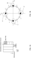
- the UE when the UCI is two bits, as shown in FIG. 1B , the UE, given four candidates (UCI candidates, candidate values, etc.) for the two-bit UCI, rotates the phase of a base sequence by selecting an amount of phase rotation that corresponds to the value to be transmitted, and transmits the phase-rotated signal using the time/frequency resource that is allocated.
- the time/frequency resource may be a time resource (for example, a subframe, a slot, a symbol, etc.) and/or a frequency resource (for example, a carrier frequency, a channel band, a CC (Component Carrier), a PRB, etc.).
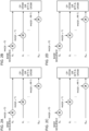
- FIGs. 2 provide diagrams to show examples of transmission signal generation processes for sequence-based PUCCHs.
- phase rotations cyclic shifts
- base sequences X 0 to X M-1 of sequence length M based on selected amounts of phase rotation ⁇
- the phase-rotated base sequences are input to a CP-OFDM (Cyclic Prefix-Orthogonal Frequency Division Multiplexing) transmitter or a DFT-S-OFDM (Discrete Fourier Transform-Spread-Orthogonal Frequency Division Multiplexing) transmitter.
- the UE transmits output signals from the CP-OFDM transmitter or the DFT-S-OFDM transmitter.
- phase rotation ⁇ 0 to ⁇ 3 in the CS candidate set are associated with UCI candidates 0 to 3, respectively, and value 0 is reported as UCI, as shown in FIG. 2A
- the UE applies phase rotations to base sequences X 0 to X M-1 , using amount of phase rotation ⁇ 0 , which is associated with value 0.
- the UE reports values 1 to 3 as UCI, as shown in FIGs. 2B, 2C and 2D
- the UE applies phase rotations to base sequences X 0 to X M-1 by using amounts of phase rotation ⁇ 1 , ⁇ 2 and ⁇ 3 , which are associated with values 1 to 3, respectively.
- the NW may detect UCI from a received signal by using maximum likelihood detection (which may be referred to as "MLD” or “correlation detection”).
- MLD maximum likelihood detection
- the network may generate replicas of all amounts of phase rotation (phase rotation amount replicas) assigned to the user terminal (for example, the network may generate four patterns of phase rotation amount replicas if the length of the UCI payload is two bits), and generate transmission signal waveforms, as the user terminal does, based on the base sequences and the phase rotation amount replicas.
- the network may calculate the correlation between the transmission signal waveforms produced thus, and the waveform of the received signal from the user terminal, for all the phase rotation amount replicas, and assume that the phase rotation amount replica to show the highest correlation has been transmitted.
- the network may multiply each element of received signal sequences of size M after the DFT (M complex-number sequences) by complex conjugates of transmission signal sequences (M complex-number sequences), which are given by applying phase rotation to the base sequence of the transmission signal based on phase rotation amount replicas, and assume that the phase rotation amount replica, where the absolute value (or the square of the absolute values) of the sum of the M sequences acquired is the largest, has been sent.
- the network may generate transmission signal replicas to match the maximum number of amounts of phase rotation that can be assigned (twelve for one PRB), and estimate the amount of phase rotation to yield the highest correlation with the received signal, based on the same operation as the MLD-based operation described above. If the estimated amount of phase rotation is different from the ones assigned, the network may assume that the amount of phase rotation that is closest to the estimated amount of phase rotation, among the assigned amounts of phase rotation, has been transmitted.
- transmission (reporting) of UCI may be read as transmission of sequence-based PUCCH.
- radio communication methods according to these embodiments may be applied individually or may be applied in combination.
- the PUCCH resource may refer to at least one of a time resource, a frequency resource and a code resource.
- the time resource may be at least one symbol.
- the time resource may be represented by a slot index, a mini-slot index, and a symbol index within a slot or a mini-slot.
- the frequency resource may be represented by, for example, a PRB index in the allocated UL BWP (Bandwidth Part, partial bandwidth, etc.).
- the frequency resource may be at least one PRB. If the frequency resource is greater than one PRB, the frequency resource may be specified by the first PRB index and the number of PRBs, or may be specified by the first PRB index and the last PRB index.
- the code resource may be a CS and/or a base sequence.
- the code resource may be specified by at least one of a CS index and a sequence index to specify a base sequence.
- Multiple UEs' sequence-based PUCCHs can be code-division-multiplexed (CDM) by allocating different code resources to different UEs, so that the spectral efficiency can be improved.
- indices, numbers, indicators and so on that specify resources are interchangeable.
- the number of CS indices that can be used for a sequence-based PUCCH may be limited. That is, fewer than twelve CSs may be assigned to UE for a sequence-based PUCCH of one PRB.
- the following first configuration method or second configuration method may be used.
- the NW signals PUCCH resources that are associated with at least one specific UCI candidate, to UE, and the UE selects PUCCH resources that are associated with another UCI candidate, among the multiple UCI candidates, based on the PUCCH resources associated with the specific UCI candidate. For example, the UE may, using an index that specifies a particular type of PUCCH resource for a particular UCI candidate, and a preconfigured algorithm, selects an index that specifies a particular type of PUCCH resource for another UCI candidate.
- the UCI includes HARQ-ACK information and/or SR information.
- the HARQ-ACK information which is one bit, represents 0 (NACK) or 1 (ACK).
- the one-bit HARQ-ACK information represents one of 00 (NACK-NACK), 01 (NACK-ACK), 11 (ACK-ACK), and 10 (ACK-NACK).
- the SR information specifies between a positive SR and a negative SR.
- UCI that includes no SR information points to a non-SR transmission timing (non-SR).
- UCI that includes a positive SR may indicate that an SR is present at an SR transmission timing, and may be referred to as "SR-including UCI.”
- UCI that includes a negative SR indicates that there is no SR at an SR transmission timing.
- UCI that includes no SR information indicates that no SR transmission timing is provided then.
- UCI that includes negative SRs and UCI that includes no SR information may be referred to as "UCI including no SR.”
- a specific UCI candidate may be a specific value of HARQ-ACK information or a specific value of SR information, may be UCI to include a specific value of SR information and a specific value of HARQ-ACK information.
- the specific value may be 0 (NACK).
- the specific value may be 00 (NACK-NACK).
- CS candidates that are provided at equal intervals may constitute a CS candidate set.
- amounts of phase rotation, which correspond to CS candidates may be provided at intervals of 2 ⁇ /the number of CS candidates in the CS candidate set (the number of candidates for HARQ-ACK information).
- the phase of a specific RE stays constant irrespective of UCI (HARQ-ACK information).
- the NW can perform channel estimation using the signal of the specific RE. That is, the NW can use the specific RE's signal as the DMRS (Demodulation Reference Signal).
- the NW may demodulate UCI based on the result of channel estimation.
- the NW may demodulate UCI based on MLD, which has been mentioned earlier, or demodulate UCI based on the result of channel estimation using the DMRS of a specific RE, or demodulate UCI by combining these.
- the NW may estimate the variance of noise using a specific RE.
- the UE can readily determine CS candidates for other UCI candidates from CS candidates for a specific UCI candidate. For example, the UE can determine other CS indices by adding the intervals between CS indices, one by one, to the CS index for a particular UCI candidate.
- the NW signals a number of PUCCH resources, which are associated with a number of UCI candidates, respectively.
- resources may be signaled through higher layer signaling (for example, RRC signaling and/or broadcast information) and/or physical layer signaling (for example, DCI (downlink control information)).
- higher layer signaling for example, RRC signaling and/or broadcast information
- physical layer signaling for example, DCI (downlink control information)
- Each configuration method may configure PUCCH resources of all types (for example, time resources, frequency resources, code resources, etc.). In addition, in each configuration method, only some types of PUCCH resources may be configured, and other types of PUCCH resources may be configured separately. Other types of PUCCH resource may be common among cells.
- the NW may configure PUCCH resources in UEs in a cell by using cell-common information (for example, broadcast information).
- the NW signals only PUCCH resources that are associated with part of multiple UCI candidates, to UEs, so that the overhead of signaling can be reduced, compared to the second configuration method.
- the NW signals a number of PUCCH resources, which are associated with a number of UCI candidates, respectively, to UEs, so that the NW can configure PUCCH resources flexibly.
- the NW signals the PUCCH resource for UCI that includes a positive SR and the PUCCH resource for a UCI that includes a negative SR, to UEs.
- the NW may signal PUCCH resource configuration information, which designates a number of PUCCH resources, through higher layer signaling, and signal or specify the PUCCH resources in the PUCCH resource configuration information through physical layer signaling. According to this signaling method, the overhead associated with signaling of PUCCH resources can be reduced, so that PUCCH resources can be changed dynamically.
- the UE may report UCI that includes a negative SR, to the NW.
- UCI that does not include SR information (“no-SR," which is UCI to include HARQ-ACK information alone, UCI to specify a non-SR transmission timing, and so on) and UCI that includes a negative SR may use the same PUCCH resources.
- This method of reporting SRs will be hereinafter referred to as the "first SR reporting method.”
- the UE may report UCI not including SR information to the NW.
- the PUCCH resources for UCI that does not include SR information may be different from the PUCCH resources for UCI that includes negative SRs. This method of reporting SRs will be hereinafter referred to as the "second SR reporting method.”
- the PUCCH resource configuration information does not have to specify the PUCCH resource for this UCI carrying SR information alone.
- the NW may signal this PUCCH resource to the UE using UE-specific information (for example, higher layer signaling).
- the PUCCH resource configuration information in this drawing specifies, for each signaling field value, the PUCCH resource for UCI that includes a specific value of HARQ-ACK information and a positive SR, and the PUCCH resource for UCI that includes a specific value of HARQ-ACK information and a negative SR.
- the specific value of HARQ-ACK information may be 0 (NACK).
- the specific value of HARQ-ACK information may be 00 (NACK-NACK).
- the NW may configure PUCCH resources in UEs according to the first SR reporting method and the second configuration method.
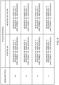
- FIG. 4 is a diagram to show examples of PUCCH resource configuration information for use in the first SR reporting method and the second configuration method when the HARQ-ACK information is one bit, according to the second embodiment.
- the PUCCH resource configuration information in this drawing specifies, for each signaling field value, the PUCCH resources for UCI that includes candidates for HARQ-ACK information (0 and 1) and a positive SR, the PUCCH resources for UCI that includes candidates for a number of pieces of HARQ-ACK information (0 and 1) and a negative SR.
- FIG. 5 is a diagram to show examples of PUCCH resource configuration information for use in the first SR reporting method and the second configuration method when the HARQ-ACK information is two bits, according to the second embodiment.
- the PUCCH resource configuration information in this drawing specifies, for each signaling field value, the PUCCH resources for UCI that includes candidates for HARQ-ACK information (00, 01, 11 and 10) and a positive SR, and the PUCCH resources for UCI that includes candidates for HARQ-ACK information (00, 01, 11 and 10) and a negative SR.
- the NW signals the PUCCH resources for UCI that includes positive SRs and the PUCCH resourced for UCI that includes negative SRs to UEs, so that the NW can configure PUCCH resources flexibly.
- the PUCCH resources for UCI not including SR information are the same as the PUCCH resources for UCI that includes negative SRs, the overhead related to signaling of PUCCH resources can be reduced, so that it is possible to reduce the volume of PUCCH resources.
- UCI that does not include SR information and UCI that includes negative SRs use different PUCCH resources.
- UCI that includes negative SRs and UCI that includes no SR information are distinguished.
- the NW and UEs can use the second SR reporting method and the first configuration method.
- FIG. 6 is a diagram to show examples of PUCCH resource configuration information for use in the second SR reporting method and the first configuration method, according to the second embodiment.
- the PUCCH resource configuration information in this drawing specifies, for each signaling field value, the PUCCH resource for UCI that includes a specific value of HARQ-ACK information and a positive SR, the PUCCH resource for UCI that includes a specific value of HARQ-ACK information and a negative SR, and the PUCCH resource for UCI that includes a specific value of HARQ-ACK information but does not include SR information.
- the specific value of HARQ-ACK information may be 0 (NACK).
- the specific value of HARQ-ACK information may be 00 (NACK-NACK).
- the NW and the UE can use the second SR reporting method and the second configuration method.
- FIG. 7 is a diagram to show examples of PUCCH resource configuration information for use in the second SR reporting method and the second configuration method when the HARQ-ACK information is one bit, according to the second embodiment.
- the PUCCH resource configuration information in this drawing specifies, for each signaling field value, the PUCCH resources for UCI that includes candidates for HARQ-ACK information (0 and 1) and a positive SR, the PUCCH resources for UCI that includes candidates for HARQ-ACK information (0 and 1) and a negative SR, and the PUCCH resources for UCI that includes candidates for HARQ-ACK information (0 and 1) but does not include SR information.
- FIG. 8 is a diagram to show examples of PUCCH resource configuration information for use in the second SR reporting method and the second configuration method when the HARQ-ACK information is two bits, according to the second embodiment.
- the PUCCH resource configuration information in this drawing specifies, for each signaling field value, the PUCCH resources for UCI that includes candidates for HARQ-ACK information (00, 01, 11 and 10) and a positive SR, the PUCCH resources for UCI that includes candidates for HARQ-ACK information (00, 01, 11 and 10) and a negative SR, and the PUCCH resources for UCI that includes candidates for HARQ-ACK information (00, 01, 11 and 10) but does not include SR information.
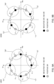
- FIGs. 9 provide diagrams to show examples of CS candidate sets assigned to each UE in the first SR reporting method.
- CS indices 0, 3, 6 and 9 are assigned to UCI that includes a negative SR and HARQ-ACK information
- CS indices 1, 4, 7 and 10 are assigned to UCI that includes a positive SR and HARQ-ACK information.
- CS indices 1, 4, 7 and 10 are assigned to UCI that includes a negative SR and HARQ-ACK information
- CS indices 2, 5, 8 and 11 are assigned to UCI that includes a positive SR and HARQ-ACK information.
- the CSI indices for UCI not including SR information are the same as the CSI indices for UCI that includes a negative SR and the HARQ-ACK information.
- the CS indices of UE #1 and the CS indices of UE #2 may overlap.
- the CS indices of UE#1 for UCI that includes a positive SR, and the CS indices of UE #2 for UCI that includes a negative SR or UCI that includes no SR information overlap.
- FIGs. 10 provide diagrams to show examples of CS candidate sets and frequency resources for UCI that includes an SR alone.
- one PRB may be allocated to UCI that only includes an SR, and two or more PRBs may be allocated to UCI that includes HARQ-ACK information.
- FIG. 11 is a diagram to show examples of timings for transmitting UCI when the first SR reporting method is used.
- the NW configures the same SR periodicity and different SR offsets for UE #1 and UE #2.
- the SR periodicity in the example in this drawing is 10 ms.
- each UE When an SR transmission timing is also a timing to transmit an HARQ-ACK, each UE transmits UCI that includes SR information and HARQ-ACK information (SR+HARQ-ACK). In the event an SR transmission timing is not a timing to transmit an HARQ-ACK, each UE transmits UCI that includes SR information alone (SR only).
- each UE When an HARQ-ACK transmission timing arrives during a period in which there is no SR transmission timing (non-SR period), each UE transmits UCI that does not include SR information but does include HARQ-ACK information (HARQ-ACK (non-SR)).
- HARQ-ACK HARQ-ACK
- FIGs. 12 provide diagrams to show examples of CS candidate sets assigned to each UE in the first SR reporting method and the second SR reporting method.
- UE #1 is assigned CS indices in accordance with the first SR reporting method.
- UE #2 is assigned CS indices in accordance with the second SR reporting method.
- CS indices 0, 3, 6 and 9 are assigned to UCI that includes a negative SR and HARQ-ACK information
- CS indices 1, 4, 7 and 10 are assigned to UCI that includes a positive SR and HARQ-ACK information.
- CS indices 1, 4, 7 and 10 are assigned to UCI that includes a negative SR and HARQ-ACK information
- CS indices 2, 5, 8 and 11 are assigned to UCI that includes a positive SR and HARQ-ACK information.
- CS indices 1, 4, 7 and 10 may be assigned to UCI that includes a positive SR and HARQ-ACK information
- CS indices 2, 5, 8 and 11 may be assigned to UCI that includes a negative SR and HARQ-ACK information.
- CS indices are assigned between UCI that includes negative SRs and UCI that includes no SR information. Also, the same CS indices are assigned to UCI that includes positive SRs and UCI that includes no SR information.
- the CS indices for UCI that includes SRs alone and the frequency resources for the sequence-based PUCCHs are the same as in FIGs. 10 .
- FIG. 13 is a diagram to show examples of timings for transmitting UCI when the first SR reporting method and the second SR reporting method are used.
- the NW signals the PUCCH resources for UCI that includes negative SRs and the PUCCH resources for UCI that does not include SR information, separately, so that, even when a number of UEs transmit UCI that includes SR information and HARQ-ACK information and UCI that includes no SR information by using the same time resource and frequency resource, collisions between CS indices can be prevented.
- the NW signals the PUCCH resource that is associated with UCI candidates that include one value of SR information (a positive SR or a negative SR), to UE, and, based on the PUCCH resource signaled, the UE selects the PUCCH resource that is associated with UCI candidates that include the other value of SR information.
- SR information a positive SR or a negative SR
- the NW may configure the PUCCH resources in the UE in accordance with the first SR reporting method and the first configuration method.
- FIG. 14 is a diagram to show examples of PUCCH resource configuration information for use in the first SR reporting method and the first configuration method, according to the third embodiment.
- the PUCCH resource configuration information in this drawing specifies the PUCCH resource for UCI that includes a specific value of HARQ-ACK information and a negative SR, for each signaling field value.
- the specific value of HARQ-ACK information may be 0 (NACK).
- the specific value of HARQ-ACK information may be 00 (NACK-NACK).
- the UE using the PUCCH resource for UCI that includes a negative SR and a given algorithm, may select the PUCCH resource for UCI that includes a positive SR.
- the UE may select a CS index of UCI that includes a positive SR by adding a given offset to a CS index of UCI that includes a negative SR. For example, if n is a CS index for UCI that includes a negative SR and y is an integer that is defined or configured in advance, then, (n+y mod the number of CS indices) gives a CS index of UCI that includes a positive SR.
- the UE may select a PRB index of UCI that includes a positive SR, by adding a given offset to a PRB index of UCI that includes a negative SR. For example, if n is a PRB index of UCI that includes a negative SR and z is an integer that is defined or configured in advance, then, (n+z mod the number of PRB indices) gives a PRB index of UCI that includes a positive SR.
- the number of CS/PRB indices may be the number of CS/PRB indices limited by signals/commands from the NW.
- y and z may be positive or negative.
- the PUCCH resources for UCI that includes positive SRs may be the same as the PUCCH resources for UCI that includes negative SRs.
- the NW may configure the PUCCH resources in UEs in accordance with the first SR reporting method and the second configuration method.
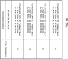
- FIG. 15 is a diagram to show examples of PUCCH resource configuration information for use in the first SR reporting method and the second configuration method when the HARQ-ACK information is one bit, according to the third embodiment.
- the PUCCH resource configuration information in this drawing specifies the PUCCH resources for UCI that includes candidates for HARQ-ACK information (0 and 1) and a negative SR, for each signaling field value.
- FIG. 16 is a diagram to show examples of PUCCH resource configuration information for use in the first SR reporting method and the second configuration method when the HARQ-ACK information is two bits, according to the third embodiment.
- the PUCCH resource configuration information in this drawing specifies the PUCCH resources for UCI that includes candidates for HARQ-ACK information (00, 01, 11 and 10) and a negative SR, for each signaling field value.
- the NW signals the PUCCH resources for UCI that includes one of a negative SR and a positive SR to UEs, and does not signal the PUCCH resources for UCI that include the other one to UEs, so that the overhead associated with signaling can be reduced.
- radio communication system communication is performed using one or a combination of the radio communication methods according to the herein-contained embodiments of the present invention.
- FIG. 17 is a diagram to show an example of a schematic structure of a radio communication system according to one embodiment of the present invention.
- a radio communication system 1 can adopt carrier aggregation (CA) and/or dual connectivity (DC) to group a number of fundamental frequency blocks (component carriers) into one, where the LTE system bandwidth (for example, 20 MHz) constitutes one unit.
- CA carrier aggregation
- DC dual connectivity
- the radio communication system 1 may be referred to as “LTE (Long Term Evolution),” “LTE-A (LTE-Advanced),” “LTE-B (LTE-Beyond),” "SUPER 3G,” “IMT-Advanced,” “4G (4th generation mobile communication system),” “5G (5th generation mobile communication system),” “NR (New Radio),” “FRA (Future Radio Access),” “New-RAT (Radio Access Technology),” and so on, or may be seen as a system to implement these.
- the radio communication system 1 includes a radio base station 11 that forms a macro cell C1, with a relatively wide coverage, and radio base stations 12a to 12c that are placed within the macro cell C1 and that form small cells C2, which are narrower than the macro cell C1. Also, user terminals 20 are placed in the macro cell C1 and in each small cell C2. The arrangement, number and so on of cells and user terminals 20 are not limited to those illustrated in the drawings.
- the user terminals 20 can connect with both the radio base station 11 and the radio base stations 12.
- the user terminals 20 may use the macro cell C1 and the small cells C2 at the same time by means of CA or DC.
- the user terminals 20 may apply CA or DC using a number of cells (CCs) (for example, five or fewer CCs or six or more CCs).
- a carrier of a relatively low frequency band for example, 2 GHz
- a narrow bandwidth referred to as, for example, an "existing carrier,” a “legacy carrier” and so on.
- a carrier of a relatively high frequency band for example, 3.5 GHz, 5 GHz and so on
- a wide bandwidth may be used, or the same carrier as that used in the radio base station 11 may be used.
- the structure of the frequency band for use in each radio base station is by no means limited to these.
- a structure may be employed here in which wire connection (for example, optical fiber, which is compliance with the CPRI (Common Public Radio Interface), the X2 interface, and so on) or wireless connection is established between the radio base station 11 and the radio base station 12 (or between two radio base stations 12).
- wire connection for example, optical fiber, which is compliance with the CPRI (Common Public Radio Interface), the X2 interface, and so on
- wireless connection is established between the radio base station 11 and the radio base station 12 (or between two radio base stations 12).
- the radio base station 11 and the radio base stations 12 are each connected with higher station apparatus 30, and are connected with a core network 40 via the higher station apparatus 30.
- the higher station apparatus 30 may be, for example, access gateway apparatus, a radio network controller (RNC), a mobility management entity (MME) and so on, but is by no means limited to these.
- RNC radio network controller
- MME mobility management entity
- each radio base station 12 may be connected with the higher station apparatus 30 via the radio base station 11.
- the radio base station 11 is a radio base station having a relatively wide coverage, and may be referred to as a "macro base station,” a “central node,” an “eNB (eNodeB),” a “transmitting/receiving point” and so on.
- the radio base stations 12 are radio base stations having local coverages, and may be referred to as “small base stations,” “micro base stations,” “pico base stations,” “femto base stations,” “HeNBs (Home eNodeBs),” “RRHs (Remote Radio Heads),” “transmitting/receiving points” and so on.
- the radio base stations 11 and 12 will be collectively referred to as “radio base stations 10,” unless specified otherwise.
- the user terminals 20 are terminals to support various communication schemes such as LTE, LTE-A and so on, and may be either mobile communication terminals (mobile stations) or stationary communication terminals (fixed stations).
- orthogonal frequency division multiple access (OFDMA) is applied to the downlink
- SC-FDMA single-carrier frequency division multiple access
- OFDMA orthogonal frequency division multiple access
- SC-FDMA single-carrier frequency division multiple access
- OFDMA is a multi-carrier communication scheme to perform communication by dividing a frequency bandwidth into a number of narrow frequency bandwidths (subcarriers) and mapping data to each subcarrier.
- SC-FDMA is a single-carrier communication scheme to mitigate interference between terminals by dividing the system bandwidth into bands formed with one or continuous resource blocks per terminal, and allowing a number of terminals to use mutually different bands.
- the radio access schemes for the uplink and the downlink are not limited to this combination, and other radio access schemes may be used as well.
- a downlink shared channel (Physical Downlink Shared CHannel)
- a broadcast channel (Physical Broadcast CHannel)
- downlink L1/L2 control channels and so on are used as downlink channels.
- User data, higher layer control information and SIBs are communicated in the PDSCH.
- SIBs System Information Blocks
- MIB Master Information Block
- scheduling information may be signaled via DCI.
- DCI to schedule receipt of DL data may be referred to as "DL assignment”
- DCI to schedule transmission of UL data may be referred to as "UL grant.”
- the user data is subjected to transmission processes, including a PDCP (Packet Data Convergence Protocol) layer process, user data division and coupling, RLC (Radio Link Control) layer transmission processes such as RLC retransmission control, MAC (Medium Access Control) retransmission control (for example, an HARQ (Hybrid Automatic Repeat reQuest) transmission process), scheduling, transport format selection, channel coding, an inverse fast Fourier transform (IFFT) process and a precoding process, and the result is forwarded to each transmitting/receiving section 103.
- downlink control signals are also subjected to transmission processes such as channel coding and an inverse fast Fourier transform, and forwarded to each transmitting/receiving section 103.
- the transmitting/receiving sections 103 may receive sequences (for example, sequence-based PUCCHs) that are associated with uplink control information (UCI).
- sequences for example, sequence-based PUCCHs
- UCI uplink control information
- the transmitting/receiving sections 103 may transmit parameters for sequence-based PUCCHs to the user terminal 20.
- FIG. 19 is a diagram to show an example of a functional structure of a radio base station according to one embodiment of the present invention. Note that, although this example primarily shows functional blocks that pertain to characteristic parts of the present embodiment, the radio base station 10 has other functional blocks that are necessary for radio communication as well.
- the baseband signal processing section 104 has a control section (scheduler) 301, a transmission signal generation section 302, a mapping section 303, a received signal processing section 304 and a measurement section 305. Note that these configurations have only to be included in the radio base station 10, and some or all of these configurations may not be included in the baseband signal processing section 104.
- the control section (scheduler) 301 controls the whole of the radio base station 10.
- the control section 301 can be constituted by a controller, a control circuit or control apparatus that can be described based on general understanding of the technical field to which the present invention pertains.
- the control section 301 controls the generation of signals in the transmission signal generation section 302, the allocation of signals by the mapping section 303, and so on. Furthermore, the control section 301 controls the signal receiving processes in the received signal processing section 304, the measurements of signals in the measurement section 305, and so on.
- the control section 301 controls the scheduling (for example, resource allocation) of system information, downlink data signals (for example, signals transmitted in the PDSCH) and downlink control signals (for example, signals transmitted in the PDCCH and/or the EPDCCH, such as delivery acknowledgement information).
- the control section 301 controls the generation of downlink control signals, downlink data signals and so on, based on the results of deciding whether or not retransmission control is necessary for uplink data signals, and so on.
- control section 301 controls the scheduling of synchronization signals (for example, the PSS (Primary Synchronization Signal)/SSS (Secondary Synchronization Signal)), downlink reference signals (for example, the CRS, the CSI-RS, the DM-RS, etc.) and so on.
- synchronization signals for example, the PSS (Primary Synchronization Signal)/SSS (Secondary Synchronization Signal)
- downlink reference signals for example, the CRS, the CSI-RS, the DM-RS, etc.
- the control section 301 also controls the scheduling of uplink data signals (for example, signals transmitted in the PUSCH), uplink control signals (for example, signals transmitted in the PUCCH and/or the PUSCH, such as delivery acknowledgment information), random access preambles (for example, signals transmitted in the PRACH), uplink reference signals, and/or other signals.
- uplink data signals for example, signals transmitted in the PUSCH
- uplink control signals for example, signals transmitted in the PUCCH and/or the PUSCH, such as delivery acknowledgment information
- random access preambles for example, signals transmitted in the PRACH
- uplink reference signals and/or other signals.
- the transmission signal generation section 302 generates downlink signals (downlink control signals, downlink data signals, downlink reference signals and so on) based on commands from the control section 301, and outputs these signals to the mapping section 303.
- the transmission signal generation section 302 can be constituted by a signal generator, a signal generating circuit or signal generating apparatus that can be described based on general understanding of the technical field to which the present invention pertains.
- the transmission signal generation section 302 generates DL assignments, which signal downlink data allocation information, and/or UL grants, which signal uplink data allocation information, based on commands from the control section 301.
- DL assignments and UL grants are both DCI, and follow the DCI format.
- the downlink data signals are subjected to the coding process, the modulation process and so on, by using coding rates and modulation schemes that are determined based on, for example, channel state information (CSI) from each user terminal 20.
- CSI channel state information
- the mapping section 303 maps the downlink signals generated in the transmission signal generation section 302 to given radio resources based on commands from the control section 301, and outputs these to the transmitting/receiving sections 103.
- the mapping section 303 can be constituted by a mapper, a mapping circuit or mapping apparatus that can be described based on general understanding of the technical field to which the present invention pertains.
- the received signal processing section 304 performs receiving processes (for example, demapping, demodulation, decoding and so on) of received signals that are input from the transmitting/receiving sections 103.
- the received signals include, for example, uplink signals transmitted from the user terminal 20 (uplink control signals, uplink data signals, uplink reference signals, etc.).
- a signal processor, a signal processing circuit or signal processing apparatus that can be described based on general understanding of the technical field to which the present invention pertains can be used.
- the received signal processing section 304 outputs the decoded information, acquired through the receiving processes, to the control section 301. For example, when a PUCCH to contain an HARQ-ACK is received, the received signal processing section 304 outputs this HARQ-ACK to the control section 301. Also, the received signal processing section 304 outputs the received signals and/or the signals after the receiving processes to the measurement section 305.
- the measurement section 305 conducts measurements with respect to the received signals.
- the measurement section 305 can be constituted by a measurer, a measurement circuit or measurement apparatus that can be described based on general understanding of the technical field to which the present invention pertains.
- the measurement section 305 may perform RRM (Radio Resource Management) measurements, CSI (Channel State Information) measurements and so on, based on the received signals.
- the measurement section 305 may measure the received power (for example, RSRP (Reference Signal Received Power)), the received quality (for example, RSRQ (Reference Signal Received Quality), SINR (Signal to Interference plus Noise Ratio), etc.), the signal strength (for example, RSSI (Received Signal Strength Indicator)), transmission path information (for example, CSI), and so on.
- the measurement results may be output to the control section 301.
- control section 301 may allocate the radio resources for sequence-based PUCCHs, to user terminals 20. Also, the control section 301 may allocate base sequences, CSs (CS candidate sets) and so on for sequence-based PUCCHs, to user terminals 20.
- CSs CS candidate sets
- FIG. 20 is a diagram to show an example of an overall structure of a user terminal according to one embodiment of the present invention.
- a user terminal 20 has a number of transmitting/receiving antennas 201, amplifying sections 202, transmitting/receiving sections 203, a baseband signal processing section 204 and an application section 205. Note that one or more transmitting/receiving antennas 201, amplifying sections 202 and transmitting/receiving sections 203 may be provided.
- Radio frequency signals that are received in the transmitting/receiving antennas 201 are amplified in the amplifying sections 202.
- the transmitting/receiving sections 203 receive the downlink signals amplified in the amplifying sections 202.
- the received signals are subjected to frequency conversion and converted into the baseband signal in the transmitting/receiving sections 203, and output to the baseband signal processing section 204.
- a transmitting/receiving section 203 can be constituted by a transmitters/receiver, a transmitting/receiving circuit or transmitting/receiving apparatus that can be described based on general understanding of the technical field to which the present invention pertains.
- a transmitting/receiving section 203 may be structured as a transmitting/receiving section in one entity, or may be constituted by a transmitting section and a receiving section.
- the baseband signal processing section 204 performs, for the baseband signal that is input, an FFT process, error correction decoding, a retransmission control receiving process and so on.
- Downlink user data is forwarded to the application section 205.
- the application section 205 performs processes related to higher layers above the physical layer and the MAC layer, and so on. Also, in the downlink data, the broadcast information can be also forwarded to the application section 205.
- uplink user data is input from the application section 205 to the baseband signal processing section 204.
- the baseband signal processing section 204 performs a retransmission control transmission process (for example, an HARQ transmission process), channel coding, precoding, a discrete Fourier transform (DFT) process, an IFFT process and so on, and the result is forwarded to the transmitting/receiving sections 203.
- Baseband signals that are output from the baseband signal processing section 204 are converted into a radio frequency band in the transmitting/receiving sections 203 and transmitted.
- the radio frequency signals that are subjected to frequency conversion in the transmitting/receiving sections 203 are amplified in the amplifying sections 202, and transmitted from the transmitting/receiving antennas 201.
- the transmitting/receiving sections 203 may transmit sequences (for example, sequence-based PUCCHs) that are associated with uplink control information (UCI).
- sequences for example, sequence-based PUCCHs
- UCI uplink control information
- the transmitting/receiving sections 203 may receive, from the radio base station 10, parameters that specify the PUCCH resources for sequence-based PUCCHs (for example, at least one of PUCCH resource configuration information, resource information and the signaling field).
- the control section 401 controls the generation of signals in the transmission signal generation section 402, the allocation of signals by the mapping section 403, and so on. Furthermore, the control section 401 controls the signal receiving processes in the received signal processing section 404, the measurements of signals in the measurement section 405, and so on.
- the control section 401 acquires the downlink control signals and downlink data signals transmitted from the radio base station 10, via the received signal processing section 404.
- the control section 401 controls the generation of uplink control signals and/or uplink data signals based on the results of deciding whether or not retransmission control is necessary for the downlink control signals and/or downlink data signals, and so on.
- the transmission signal generation section 402 generates uplink signals (uplink control signals, uplink data signals, uplink reference signals, etc.) based on commands from the control section 401, and outputs these signals to the mapping section 403.
- the transmission signal generation section 402 can be constituted by a signal generator, a signal generating circuit or signal generating apparatus that can be described based on general understanding of the technical field to which the present invention pertains.
- the received signal processing section 404 outputs the decoded information, acquired through the receiving processes, to the control section 401.
- the received signal processing section 404 outputs, for example, broadcast information, system information, RRC signaling, DCI and so on, to the control section 401. Also, the received signal processing section 404 outputs the received signals and/or the signals after the receiving processes to the measurement section 405.
- the measurement section 405 may perform RRM measurements, CSI measurements and so on based on the received signals.
- the measurement section 405 may measure the received power (for example, RSRP), the received quality (for example, RSRQ, SINR, etc.), the signal strength (for example, RSSI), transmission path information (for example, CSI), and so on.
- the measurement results may be output to the control section 401.
- control section 401 may control the selection of radio resources for use for transmitting a sequence (for example, a sequence-based PUCCH), from among a number of radio resources (for example, PUCCH resources) designated in configuration information (for example, PUCCH resource configuration information) signaled from the radio base station 10, based on radio resources associated with identification information (for example, the signaling field) signaled from the radio base station 10.
- a sequence for example, a sequence-based PUCCH
- configuration information for example, PUCCH resource configuration information
- the multiple radio resources may each include a cyclic shift and/or a base sequence for the sequence.
- the multiple radio resources may be each associated with one of uplink control information including a scheduling request and uplink control information not including a scheduling request. Then, based on the radio resource associated with the identification information, the control section 401 may select the radio resources associated with the other uplink control information (third embodiment).
- each functional block may be realized by one piece of apparatus that is physically and/or logically integrated, or may be realized by directly and/or indirectly connecting two or more physically and/or logically separate pieces of apparatus (via wire or wireless, for example) and using these multiple pieces of apparatus.
- processor 1001 may be implemented with one or more chips.
- Each function of the radio base station 10 and the user terminal 20 is implemented by reading given software (program) on hardware such as the processor 1001 and the memory 1002, and by controlling the calculations in the processor 1001, the communication in the communication apparatus 1004, and the reading and/or writing of data in the memory 1002 and the storage 1003.
- software program
- the processor 1001 may control the whole computer by, for example, running an operating system.
- the processor 1001 may be configured with a central processing unit (CPU), which includes interfaces with peripheral apparatus, control apparatus, computing apparatus, registers and so on.
- CPU central processing unit
- the above-described baseband signal processing section 104 (204), call processing section 105 and others may be implemented by the processor 1001.
- the storage 1003 is a computer-readable recording medium, and may be constituted by, for example, at least one of a flexible disk, a floppy (registered trademark) disk, a magneto-optical disk (for example, a compact disc (CD-ROM (Compact Disc ROM) and so on), a digital versatile disc, a Blu-ray (registered trademark) disk), a removable disk, a hard disk drive, a smart card, a flash memory device (for example, a card, a stick, a key drive, etc.), a magnetic stripe, a database, a server, and/or other appropriate storage media.
- the storage 1003 may be referred to as "secondary storage apparatus.”
- a reference signal may be abbreviated as an "RS,” and may be referred to as a "pilot,” a “pilot signal” and so on, depending on which standard applies.
- a “component carrier (CC)” may be referred to as a "cell,” a “frequency carrier,” a “carrier frequency” and so on.
- a radio frame may be comprised of one or more periods (frames) in the time domain.
- Each of one or more periods (frames) constituting a radio frame may be referred to as a "subframe.”
- a subframe may be comprised of one or more slots in the time domain.
- a subframe may be a fixed time duration (for example, 1 ms) that does not depend on numerology.
- a slot may be comprised of one or more symbols in the time domain (OFDM (Orthogonal Frequency Division Multiplexing) symbols, SC-FDMA (Single Carrier Frequency Division Multiple Access) symbols, and so on).
- a slot may be a time unit based on numerology.
- a slot may include a number of minislots. Each mini-slot may consist of one or more symbols in the time domain. Also, a minislot may be referred to as a "subslot.”
- a radio frame, a subframe, a slot, a minislot and a symbol all represent the time unit in signal communication.
- a radio frame, a subframe, a slot, a minislot and a symbol may be each called by other applicable names.
- one subframe may be referred to as a "transmission time interval (TTI)," or a number of consecutive subframes may be referred to as a "TTI,” or one slot or minislot may be referred to as a "TTI.”
- TTI transmission time interval
- a subframe and/or a TTI may be a subframe (1 ms) in existing LTE, may be a shorter period than 1 ms (for example, one to thirteen symbols), or may be a longer period of time than 1 ms.
- the unit to represent the TTI may be referred to as a "slot,” a "mini slot” and so on, instead of a "subframe.”
- a TTI refers to the minimum time unit of scheduling in radio communication, for example.
- a radio base station schedules the radio resources (such as the frequency bandwidth and transmission power that can be used in each user terminal) to allocate to each user terminal in TTI units.
- the definition of TTIs is not limited to this.
- the TTI may be the transmission time unit of channel-encoded data packets (transport blocks), code blocks and/or codewords, or may be the unit of processing in scheduling, link adaptation and so on. Note that, when a TTI is given, the period of time (for example, the number of symbols) in which transport blocks, code blocks and/or codewords are actually mapped may be shorter than the TTI.
- one or more TTIs may be the minimum time unit of scheduling.
- the number of slots (the number of minislots) to constitute this minimum time unit of scheduling may be controlled.
- a long TTI for example, a normal TTI, a subframe, etc.
- a short TTI for example, a shortened TTI
- a TTI duration less than the TTI duration of a long TTI and not less than 1 ms.
- a resource block is the unit of resource allocation in the time domain and the frequency domain, and may include one or a number of consecutive subcarriers in the frequency domain. Also, an RB may include one or more symbols in the time domain, and may be one slot, one minislot, one subframe or one TTI in length. One TTI and one subframe each may be comprised of one or more resource blocks. Note that one or more RBs may be referred to as a "physical resource block (PRB (Physical RB)),” a “subcarrier group (SCG),” a “resource element group (REG),” a "PRB pair,” an “RB pair” and so on.
- PRB Physical resource block
- SCG subcarrier group
- REG resource element group
- a resource block may be comprised of one or more resource elements (REs).
- REs resource elements
- one RE may be a radio resource region of one subcarrier and one symbol.
- radio frames, subframes, slots, minislots, symbols and so on described above are merely examples.
- configurations pertaining to the number of subframes included in a radio frame, the number of slots per subframe or radio frame, the number of minislots included in a slot, the number of symbols and RBs included in a slot or a minislot, the number of subcarriers included in an RB, the number of symbols in a TTI, the symbol duration, the length of cyclic prefixes (CPs) and so on can be variously changed.
- the information, signals and so on that are input and/or output may be stored in a specific location (for example, a memory), or may be managed using a management table.
- the information, signals and so on to be input and/or output can be overwritten, updated or appended.
- the information, signals and so on that are output may be deleted.
- the information, signals and so on that are input may be transmitted to other pieces of apparatus.
- Signaling of information is by no means limited to the aspects/embodiments described in this specification, and other methods may be used as well.
- signaling of information may be implemented by using physical layer signaling (for example, downlink control information (DCI), uplink control information (UCI), higher layer signaling (for example, RRC (Radio Resource Control) signaling, broadcast information (the master information block (MIB), system information blocks (SIBs) and so on), MAC (Medium Access Control) signaling and so on), and other signals and/or combinations of these.
- DCI downlink control information
- UCI uplink control information
- higher layer signaling for example, RRC (Radio Resource Control) signaling
- broadcast information the master information block (MIB), system information blocks (SIBs) and so on
- MAC Medium Access Control
- L1/L2 Layer 1/Layer 2 control signals
- L1 control information L1 control signal
- RRC signaling may be referred to as “RRC messages,” and can be, for example, an RRC connection setup message, RRC connection reconfiguration message, and so on.
- MAC signaling may be signaled using, for example, MAC control elements (MAC CEs (Control Elements)).
- signaling of given information does not necessarily have to be sent explicitly, and can be sent implicitly (for example, by not signaling this piece of information, by signaling another piece of information, and so on).
- Decisions may be made in values represented by one bit (0 or 1), may be made in Boolean values that represent true or false, or may be made by comparing numerical values (for example, comparison against a given value).
- Software whether referred to as “software,” “firmware,” “middleware,” “microcode” or “hardware description language,” or called by other names, should be interpreted broadly, to mean instructions, instruction sets, code, code segments, program codes, programs, subprograms, software modules, applications, software applications, software packages, routines, subroutines, objects, executable files, execution threads, procedures, functions and so on.
- software, commands, information and so on may be transmitted and received via communication media.
- communication media For example, when software is transmitted from a website, a server or other remote sources by using wired technologies (coaxial cables, optical fiber cables, twisted-pair cables, digital subscriber lines (DSL) and so on) and/or wireless technologies (infrared radiation, microwaves and so on), these wired technologies and/or wireless technologies are also included in the definition of communication media.
- wired technologies coaxial cables, optical fiber cables, twisted-pair cables, digital subscriber lines (DSL) and so on
- wireless technologies infrared radiation, microwaves and so on
- system and "network” as used herein are used interchangeably.
- base station As used herein, the terms “base station (BS),” “radio base station,” “eNB,” “gNB,” “cell,” “sector,” “cell group,” “carrier,” and “component carrier” may be used interchangeably.
- a base station may be referred to as a “fixed station,” “NodeB,” “eNodeB (eNB),” “access point,” “transmission point,” “receiving point,” “femto cell,” “small cell” and so on.
- a base station can accommodate one or more (for example, three) cells (also referred to as "sectors"). When a base station accommodates a number of cells, the entire coverage area of the base station can be partitioned into multiple smaller areas, and each smaller area can provide communication services through base station subsystems (for example, indoor small base stations (RRHs (Remote Radio Heads))).
- RRHs Remote Radio Heads
- the term "cell” or “sector” refers to part or all of the coverage area of a base station and/or a base station subsystem that provides communication services within this coverage.
- MS mobile station
- UE user equipment
- terminal terminal
- a base station may be referred to as a "fixed station,” “NodeB,” “eNodeB (eNB),” "access point,” “transmission point,” “receiving point,” “femto cell,” “small cell” and so on.
- a mobile station may be referred to, by a person skilled in the art, as a "subscriber station,” “mobile unit,” “subscriber unit,” “wireless unit,” “remote unit,” “mobile device,” “wireless device,” “wireless communication device,” “remote device,” “mobile subscriber station,” “access terminal,” “mobile terminal,” “wireless terminal,” “remote terminal,” “handset,” “user agent,” “mobile client,” “client” or some other suitable terms.
- radio base stations in this specification may be interpreted as user terminals.
- each aspect/embodiment of the present invention may be applied to a configuration in which communication between a radio base station and a user terminal is replaced with communication among a number of user terminals (D2D (Device-to-Device)).
- user terminals 20 may have the functions of the radio base stations 10 described above.
- terms such as "uplink” and “downlink” may be interpreted as "side.”
- an uplink channel may be interpreted as a side channel.
- the user terminals in this specification may be interpreted as radio base stations.
- the radio base stations 10 may have the functions of the user terminals 20 described above.
- base stations may, in some cases, be performed by its higher nodes (upper nodes).
- upper nodes In a network comprised of one or more network nodes with base stations, it is clear that various operations that are performed so as to communicate with terminals can be performed by base stations, one or more network nodes (for example, MMEs (Mobility Management Entities), S-GWs (Serving-Gateways) and so on may be possible, but these are not limiting) other than base stations, or combinations of these.
- MMEs Mobility Management Entities
- S-GWs Serving-Gateways
- LTE Long Term Evolution
- LTE-A Long Term Evolution
- LTE-B Long Term Evolution-Beyond
- SUPER 3G IMT-Advanced
- 4G 4th generation mobile communication system
- 5G 5th generation mobile communication system
- FRA Fluture Radio Access
- New-RAT Radio Access Technology
- NR New Radio
- NX New radio access
- FX Fluture generation radio access
- GSM registered trademark
- CDMA 2000 UMB (Ultra Mobile Broadband)
- IEEE 802.11 Wi-Fi (registered trademark)
- IEEE 802.16 WiMAX (registered trademark)
- IEEE 802.20 UWB (Ultra-WideBand
- Bluetooth registered trademark
- references to elements with designations such as “first,” “second” and so on as used herein does not generally limit the number/quantity or order of these elements. These designations are used herein only for convenience, as a method of distinguishing between two or more elements. In this way, reference to the first and second elements does not imply that only two elements may be employed, or that the first element must precede the second element in some way.
- judge and “determine” as used herein may encompass a wide variety of actions. For example, to “judge” and “determine” as used herein may be interpreted to mean making judgements and determinations related to calculating, computing, processing, deriving, investigating, looking up (for example, searching a table, a database or some other data structure), ascertaining and so on. Furthermore, to “judge” and “determine” as used herein may be interpreted to mean making judgements and determinations related to receiving (for example, receiving information), transmitting (for example, transmitting information), inputting, outputting, accessing (for example, accessing data in a memory) and so on.
- connection means all direct or indirect connections or coupling between two or more elements, and may include the presence of one or more intermediate elements between two elements that are “connected” or “coupled” to each other.
- the coupling or connection between the elements may be physical, logical or a combination thereof. For example, “connection” may be interpreted as "access.”
- two elements may be considered “connected” or “coupled” to each other by using one or more electrical wires, cables and/or printed electrical connections, and, as a number of non-limiting and non-inclusive examples, by using electromagnetic energy, such as electromagnetic energy having wavelengths in radio frequency regions, microwave regions and optical regions (both visible and invisible).
- electromagnetic energy such as electromagnetic energy having wavelengths in radio frequency regions, microwave regions and optical regions (both visible and invisible).
Landscapes
- Engineering & Computer Science (AREA)
- Signal Processing (AREA)
- Computer Networks & Wireless Communication (AREA)
- Mobile Radio Communication Systems (AREA)
Claims (3)
- Endgerät (20), das für den Betrieb in einem 3GPP-System konfiguriert ist, wobei das Endgerät Folgendes umfasst:einen Steuerabschnitt (401), der so konfiguriert ist, dass er Ressourceninformationen verwendet, die durch ein Ressourcenindikatorfeld in Downlink-Steuerinformationen aus einer Vielzahl von Ressourceninformationen angezeigt werden, die durch eine Signalisierung auf höherer Ebene konfiguriert sind, um die Übertragung von Uplink-Steuerinformationen, UCI (Uplink Control Information), auf einem physikalischen Uplink-Steuerkanal, PUCCH (Physical Uplink Control Channel), zu steuern,wobei die Ressourceninformationen einen spezifischen zyklischen Verschiebungsindex, CS (Cyclic Shift), einschließen und der Steuerabschnitt (401) so konfiguriert ist, dass er einen CS-Index auf der Grundlage des spezifischen CS-Index und der UCI bestimmt; undeinen Übertragungsabschnitt (203), der so konfiguriert ist, dass er eine Sequenz unter Verwendung des CS-Index im PUCCH überträgt,wobei, wenn die UCI die Information HARQ-ACK (Hybrid Automatic Repeat Request-ACKnowledgement) mit einer negativen Zeitplanungsanforderung (SR, Scheduling Request) einschließen, der CS-Index der spezifische CS-Index ist;wobei, wenn die UCI die HARQ-ACK-Information mit einer positiven SR einschließen, der CS-Index durch Addieren eines CS-Offsets zu dem spezifischen CS-Index erhalten wird.
- Funkkommunikationsverfahren für ein Endgerät (20), das für den Betrieb in einem 3GPP-System konfiguriert ist, wobei das Verfahren Folgendes umfasst:Verwenden von Ressourceninformationen,, die durch ein Ressourcenindikatorfeld in Downlink-Steuerinformationen aus einer Vielzahl von Ressourceninformationen angezeigt werden, die durch eine Signalisierung auf höherer Ebene konfiguriert sind, um die Übertragung von Uplink-Steuerinformationen, UCI, auf einem physikalischen Uplink-Steuerkanal, PUCCH, zu steuern, wobei die Ressourceninformationen einen spezifischen zyklischen Verschiebungsindex, CS, einschließen;Bestimmen eines CS-Index auf der Grundlage des spezifischen CS-Index und der UCI; undÜbertragen einer Sequenz unter Verwendung des CS-Index im PUCCH,wobei, wenn die UCI die Information HARQ-ACK (Hybrid Automatic Repeat Request-ACKnowledgement) mit einer negativen Zeitplanungsanforderung (SR, Scheduling Request) einschließen, der CS-Index der spezifische CS-Index ist;wobei, wenn die UCI die HARQ-ACK-Information mit einer positiven SR einschließen, der CS-Index durch Addieren eines CS-Offsets zu dem spezifischen CS-Index erhalten wird.
- System (1), das das Endgerät (20) nach Anspruch 1 und eine Basisstation (10) umfasst, die zum Empfang der Sequenz im PUCCH konfiguriert ist.
Priority Applications (1)
| Application Number | Priority Date | Filing Date | Title |
|---|---|---|---|
| HUE17925430A HUE070528T2 (hu) | 2017-09-15 | 2017-09-15 | Felhasználói terminál és vezeték nélküli kommunikációs eljárás |
Applications Claiming Priority (1)
| Application Number | Priority Date | Filing Date | Title |
|---|---|---|---|
| PCT/JP2017/033598 WO2019053903A1 (ja) | 2017-09-15 | 2017-09-15 | ユーザ端末及び無線通信方法 |
Publications (3)
| Publication Number | Publication Date |
|---|---|
| EP3684119A1 EP3684119A1 (de) | 2020-07-22 |
| EP3684119A4 EP3684119A4 (de) | 2021-04-21 |
| EP3684119B1 true EP3684119B1 (de) | 2025-03-05 |
Family
ID=65723283
Family Applications (1)
| Application Number | Title | Priority Date | Filing Date |
|---|---|---|---|
| EP17925430.5A Active EP3684119B1 (de) | 2017-09-15 | 2017-09-15 | Benutzerendgerät und drahtloskommunikationsverfahren |
Country Status (10)
| Country | Link |
|---|---|
| US (1) | US11432315B2 (de) |
| EP (1) | EP3684119B1 (de) |
| JP (1) | JP7234117B2 (de) |
| CN (1) | CN111345086B (de) |
| BR (1) | BR112020004973A2 (de) |
| CO (1) | CO2020004238A2 (de) |
| ES (1) | ES3017691T3 (de) |
| HU (1) | HUE070528T2 (de) |
| PL (1) | PL3684119T3 (de) |
| WO (1) | WO2019053903A1 (de) |
Families Citing this family (8)
| Publication number | Priority date | Publication date | Assignee | Title |
|---|---|---|---|---|
| CN109391425B (zh) * | 2017-08-11 | 2020-10-16 | 电信科学技术研究院 | 一种信息的传输方法、终端及基站 |
| JP7377966B2 (ja) | 2019-10-04 | 2023-11-10 | テレフオンアクチーボラゲット エルエム エリクソン(パブル) | Nr-uにおけるセル再設定に適応性のあるユーザ機器の挙動のための方法 |
| WO2021074827A1 (en) | 2019-10-15 | 2021-04-22 | Telefonaktiebolaget Lm Ericsson (Publ) | Systems and methods for reliable mac ce ack/nack confirmation |
| WO2022015596A1 (en) | 2020-07-15 | 2022-01-20 | Qualcomm Incorporated | Techniques for random access communication support using remotely-located nodes in a wireless network |
| WO2022038919A1 (ja) * | 2020-08-17 | 2022-02-24 | 株式会社Nttドコモ | 端末及び通信方法 |
| CN115118394B (zh) * | 2021-03-19 | 2025-09-16 | 中国移动通信有限公司研究院 | 混合自动重传请求信息的处理方法、装置和通信设备 |
| US12507222B2 (en) * | 2022-04-12 | 2025-12-23 | Qualcomm Incorporated | Joint indication for multi-cell scheduling |
| WO2024194989A1 (ja) * | 2023-03-20 | 2024-09-26 | 日本電気株式会社 | 通信装置、通信制御方法、及び非一時的なコンピュータ可読媒体 |
Family Cites Families (6)
| Publication number | Priority date | Publication date | Assignee | Title |
|---|---|---|---|---|
| JP5301323B2 (ja) * | 2009-03-16 | 2013-09-25 | 株式会社エヌ・ティ・ティ・ドコモ | 移動端末装置及び無線通信方法 |
| JP2013034115A (ja) * | 2011-08-02 | 2013-02-14 | Sharp Corp | 基地局、端末、通信システムおよび通信方法 |
| CN106411475B (zh) * | 2015-07-27 | 2019-05-24 | 中兴通讯股份有限公司 | 一种反馈传输方法及装置 |
| US10516460B2 (en) * | 2016-02-26 | 2019-12-24 | Lg Electronics Inc. | Method and apparatus for transmitting and receiving wireless signal in wireless communication system |
| JP2019125816A (ja) * | 2016-05-12 | 2019-07-25 | シャープ株式会社 | 端末装置および方法 |
| US11012983B2 (en) * | 2016-07-26 | 2021-05-18 | Lg Electronics Inc. | Method for transmitting uplink control information by terminal in wireless communication system and device for supporting same |
-
2017
- 2017-09-15 PL PL17925430.5T patent/PL3684119T3/pl unknown
- 2017-09-15 ES ES17925430T patent/ES3017691T3/es active Active
- 2017-09-15 BR BR112020004973-5A patent/BR112020004973A2/pt unknown
- 2017-09-15 EP EP17925430.5A patent/EP3684119B1/de active Active
- 2017-09-15 HU HUE17925430A patent/HUE070528T2/hu unknown
- 2017-09-15 CN CN201780096780.6A patent/CN111345086B/zh active Active
- 2017-09-15 JP JP2019541616A patent/JP7234117B2/ja active Active
- 2017-09-15 US US16/647,361 patent/US11432315B2/en active Active
- 2017-09-15 WO PCT/JP2017/033598 patent/WO2019053903A1/ja not_active Ceased
-
2020
- 2020-04-06 CO CONC2020/0004238A patent/CO2020004238A2/es unknown
Also Published As
| Publication number | Publication date |
|---|---|
| ES3017691T3 (en) | 2025-05-13 |
| US11432315B2 (en) | 2022-08-30 |
| HUE070528T2 (hu) | 2025-06-28 |
| CN111345086B (zh) | 2023-08-15 |
| JPWO2019053903A1 (ja) | 2020-10-15 |
| US20210185712A1 (en) | 2021-06-17 |
| BR112020004973A2 (pt) | 2020-09-15 |
| CN111345086A (zh) | 2020-06-26 |
| EP3684119A4 (de) | 2021-04-21 |
| WO2019053903A1 (ja) | 2019-03-21 |
| CO2020004238A2 (es) | 2020-08-31 |
| EP3684119A1 (de) | 2020-07-22 |
| PL3684119T3 (pl) | 2025-05-05 |
| JP7234117B2 (ja) | 2023-03-07 |
Similar Documents
| Publication | Publication Date | Title |
|---|---|---|
| US11201771B2 (en) | User terminal and radio communication method | |
| EP3579643B1 (de) | Benutzerendgerät und radiokommunikationsverfahren | |
| EP3579512B1 (de) | Benutzerendgerät und drahtloskommunikationsverfahren | |
| EP3621378B1 (de) | Benutzerendgerät und drahtloskommunikationsverfahren | |
| EP3634052B1 (de) | Endgerät, funkkommunikationsverfahren und system | |
| US11483806B2 (en) | User terminal and radio communication method | |
| US11432315B2 (en) | User terminal and radio communication method | |
| US11240788B2 (en) | User terminal and radio communication method | |
| EP3644566B1 (de) | Benutzerendgerät und drahtloskommunikationsverfahren | |
| EP3634067B1 (de) | Benutzerendgerät und drahtloskommunikationsverfahren | |
| US11350392B2 (en) | User terminal and radio communication method | |
| CA3044647C (en) | User terminal and radio communication method | |
| CA3052126C (en) | User terminal and radio communication method |
Legal Events
| Date | Code | Title | Description |
|---|---|---|---|
| STAA | Information on the status of an ep patent application or granted ep patent |
Free format text: STATUS: THE INTERNATIONAL PUBLICATION HAS BEEN MADE |
|
| PUAI | Public reference made under article 153(3) epc to a published international application that has entered the european phase |
Free format text: ORIGINAL CODE: 0009012 |
|
| STAA | Information on the status of an ep patent application or granted ep patent |
Free format text: STATUS: REQUEST FOR EXAMINATION WAS MADE |
|
| 17P | Request for examination filed |
Effective date: 20200401 |
|
| AK | Designated contracting states |
Kind code of ref document: A1 Designated state(s): AL AT BE BG CH CY CZ DE DK EE ES FI FR GB GR HR HU IE IS IT LI LT LU LV MC MK MT NL NO PL PT RO RS SE SI SK SM TR |
|
| AX | Request for extension of the european patent |
Extension state: BA ME |
|
| DAV | Request for validation of the european patent (deleted) | ||
| DAX | Request for extension of the european patent (deleted) | ||
| A4 | Supplementary search report drawn up and despatched |
Effective date: 20210324 |
|
| RIC1 | Information provided on ipc code assigned before grant |
Ipc: H04W 72/04 20090101AFI20210318BHEP Ipc: H04L 1/18 20060101ALI20210318BHEP Ipc: H04L 5/00 20060101ALI20210318BHEP |
|
| STAA | Information on the status of an ep patent application or granted ep patent |
Free format text: STATUS: EXAMINATION IS IN PROGRESS |
|
| 17Q | First examination report despatched |
Effective date: 20211223 |
|
| P01 | Opt-out of the competence of the unified patent court (upc) registered |
Effective date: 20230509 |
|
| GRAP | Despatch of communication of intention to grant a patent |
Free format text: ORIGINAL CODE: EPIDOSNIGR1 |
|
| STAA | Information on the status of an ep patent application or granted ep patent |
Free format text: STATUS: GRANT OF PATENT IS INTENDED |
|
| INTG | Intention to grant announced |
Effective date: 20241105 |
|
| GRAS | Grant fee paid |
Free format text: ORIGINAL CODE: EPIDOSNIGR3 |
|
| GRAA | (expected) grant |
Free format text: ORIGINAL CODE: 0009210 |
|
| STAA | Information on the status of an ep patent application or granted ep patent |
Free format text: STATUS: THE PATENT HAS BEEN GRANTED |
|
| AK | Designated contracting states |
Kind code of ref document: B1 Designated state(s): AL AT BE BG CH CY CZ DE DK EE ES FI FR GB GR HR HU IE IS IT LI LT LU LV MC MK MT NL NO PL PT RO RS SE SI SK SM TR |
|
| REG | Reference to a national code |
Ref country code: GB Ref legal event code: FG4D |
|
| REG | Reference to a national code |
Ref country code: CH Ref legal event code: EP |
|
| REG | Reference to a national code |
Ref country code: IE Ref legal event code: FG4D |
|
| REG | Reference to a national code |
Ref country code: DE Ref legal event code: R096 Ref document number: 602017088231 Country of ref document: DE |
|
| REG | Reference to a national code |
Ref country code: NL Ref legal event code: FP |
|
| REG | Reference to a national code |
Ref country code: ES Ref legal event code: FG2A Ref document number: 3017691 Country of ref document: ES Kind code of ref document: T3 Effective date: 20250513 |
|
| REG | Reference to a national code |
Ref country code: HU Ref legal event code: AG4A Ref document number: E070528 Country of ref document: HU |
|
| PG25 | Lapsed in a contracting state [announced via postgrant information from national office to epo] |
Ref country code: RS Free format text: LAPSE BECAUSE OF FAILURE TO SUBMIT A TRANSLATION OF THE DESCRIPTION OR TO PAY THE FEE WITHIN THE PRESCRIBED TIME-LIMIT Effective date: 20250605 |
|
| PG25 | Lapsed in a contracting state [announced via postgrant information from national office to epo] |
Ref country code: FI Free format text: LAPSE BECAUSE OF FAILURE TO SUBMIT A TRANSLATION OF THE DESCRIPTION OR TO PAY THE FEE WITHIN THE PRESCRIBED TIME-LIMIT Effective date: 20250305 |
|
| REG | Reference to a national code |
Ref country code: LT Ref legal event code: MG9D |
|
| PG25 | Lapsed in a contracting state [announced via postgrant information from national office to epo] |
Ref country code: NO Free format text: LAPSE BECAUSE OF FAILURE TO SUBMIT A TRANSLATION OF THE DESCRIPTION OR TO PAY THE FEE WITHIN THE PRESCRIBED TIME-LIMIT Effective date: 20250605 |
|
| PG25 | Lapsed in a contracting state [announced via postgrant information from national office to epo] |
Ref country code: HR Free format text: LAPSE BECAUSE OF FAILURE TO SUBMIT A TRANSLATION OF THE DESCRIPTION OR TO PAY THE FEE WITHIN THE PRESCRIBED TIME-LIMIT Effective date: 20250305 |
|
| PG25 | Lapsed in a contracting state [announced via postgrant information from national office to epo] |
Ref country code: LV Free format text: LAPSE BECAUSE OF FAILURE TO SUBMIT A TRANSLATION OF THE DESCRIPTION OR TO PAY THE FEE WITHIN THE PRESCRIBED TIME-LIMIT Effective date: 20250305 |
|
| PG25 | Lapsed in a contracting state [announced via postgrant information from national office to epo] |
Ref country code: GR Free format text: LAPSE BECAUSE OF FAILURE TO SUBMIT A TRANSLATION OF THE DESCRIPTION OR TO PAY THE FEE WITHIN THE PRESCRIBED TIME-LIMIT Effective date: 20250606 Ref country code: BG Free format text: LAPSE BECAUSE OF FAILURE TO SUBMIT A TRANSLATION OF THE DESCRIPTION OR TO PAY THE FEE WITHIN THE PRESCRIBED TIME-LIMIT Effective date: 20250305 |
|
| REG | Reference to a national code |
Ref country code: AT Ref legal event code: MK05 Ref document number: 1774126 Country of ref document: AT Kind code of ref document: T Effective date: 20250305 |
|
| PG25 | Lapsed in a contracting state [announced via postgrant information from national office to epo] |
Ref country code: SE Free format text: LAPSE BECAUSE OF FAILURE TO SUBMIT A TRANSLATION OF THE DESCRIPTION OR TO PAY THE FEE WITHIN THE PRESCRIBED TIME-LIMIT Effective date: 20250305 |
|
| PG25 | Lapsed in a contracting state [announced via postgrant information from national office to epo] |
Ref country code: SM Free format text: LAPSE BECAUSE OF FAILURE TO SUBMIT A TRANSLATION OF THE DESCRIPTION OR TO PAY THE FEE WITHIN THE PRESCRIBED TIME-LIMIT Effective date: 20250305 |
|
| PG25 | Lapsed in a contracting state [announced via postgrant information from national office to epo] |
Ref country code: PT Free format text: LAPSE BECAUSE OF FAILURE TO SUBMIT A TRANSLATION OF THE DESCRIPTION OR TO PAY THE FEE WITHIN THE PRESCRIBED TIME-LIMIT Effective date: 20250707 |
|
| PGFP | Annual fee paid to national office [announced via postgrant information from national office to epo] |
Ref country code: DE Payment date: 20250925 Year of fee payment: 9 |
|
| PGFP | Annual fee paid to national office [announced via postgrant information from national office to epo] |
Ref country code: NL Payment date: 20250926 Year of fee payment: 9 Ref country code: PL Payment date: 20250814 Year of fee payment: 9 Ref country code: IT Payment date: 20250926 Year of fee payment: 9 |
|
| PGFP | Annual fee paid to national office [announced via postgrant information from national office to epo] |
Ref country code: BE Payment date: 20250926 Year of fee payment: 9 Ref country code: HU Payment date: 20250808 Year of fee payment: 9 Ref country code: GB Payment date: 20250926 Year of fee payment: 9 |
|
| PG25 | Lapsed in a contracting state [announced via postgrant information from national office to epo] |
Ref country code: AT Free format text: LAPSE BECAUSE OF FAILURE TO SUBMIT A TRANSLATION OF THE DESCRIPTION OR TO PAY THE FEE WITHIN THE PRESCRIBED TIME-LIMIT Effective date: 20250305 |
|
| PG25 | Lapsed in a contracting state [announced via postgrant information from national office to epo] |
Ref country code: CZ Free format text: LAPSE BECAUSE OF FAILURE TO SUBMIT A TRANSLATION OF THE DESCRIPTION OR TO PAY THE FEE WITHIN THE PRESCRIBED TIME-LIMIT Effective date: 20250305 Ref country code: EE Free format text: LAPSE BECAUSE OF FAILURE TO SUBMIT A TRANSLATION OF THE DESCRIPTION OR TO PAY THE FEE WITHIN THE PRESCRIBED TIME-LIMIT Effective date: 20250305 |
|
| PG25 | Lapsed in a contracting state [announced via postgrant information from national office to epo] |
Ref country code: RO Free format text: LAPSE BECAUSE OF FAILURE TO SUBMIT A TRANSLATION OF THE DESCRIPTION OR TO PAY THE FEE WITHIN THE PRESCRIBED TIME-LIMIT Effective date: 20250305 |
|
| PG25 | Lapsed in a contracting state [announced via postgrant information from national office to epo] |
Ref country code: SK Free format text: LAPSE BECAUSE OF FAILURE TO SUBMIT A TRANSLATION OF THE DESCRIPTION OR TO PAY THE FEE WITHIN THE PRESCRIBED TIME-LIMIT Effective date: 20250305 |
|
| PG25 | Lapsed in a contracting state [announced via postgrant information from national office to epo] |
Ref country code: IS Free format text: LAPSE BECAUSE OF FAILURE TO SUBMIT A TRANSLATION OF THE DESCRIPTION OR TO PAY THE FEE WITHIN THE PRESCRIBED TIME-LIMIT Effective date: 20250705 |
|
| REG | Reference to a national code |
Ref country code: DE Ref legal event code: R097 Ref document number: 602017088231 Country of ref document: DE |
|
| PLBE | No opposition filed within time limit |
Free format text: ORIGINAL CODE: 0009261 |
|
| STAA | Information on the status of an ep patent application or granted ep patent |
Free format text: STATUS: NO OPPOSITION FILED WITHIN TIME LIMIT |
|
| PG25 | Lapsed in a contracting state [announced via postgrant information from national office to epo] |
Ref country code: DK Free format text: LAPSE BECAUSE OF FAILURE TO SUBMIT A TRANSLATION OF THE DESCRIPTION OR TO PAY THE FEE WITHIN THE PRESCRIBED TIME-LIMIT Effective date: 20250305 |
|
| REG | Reference to a national code |
Ref country code: CH Ref legal event code: L10 Free format text: ST27 STATUS EVENT CODE: U-0-0-L10-L00 (AS PROVIDED BY THE NATIONAL OFFICE) Effective date: 20260114 |
|
| PGFP | Annual fee paid to national office [announced via postgrant information from national office to epo] |
Ref country code: ES Payment date: 20251001 Year of fee payment: 9 |
|
| 26N | No opposition filed |
Effective date: 20251208 |
|
| REG | Reference to a national code |
Ref country code: CH Ref legal event code: H13 Free format text: ST27 STATUS EVENT CODE: U-0-0-H10-H13 (AS PROVIDED BY THE NATIONAL OFFICE) Effective date: 20260425 |