EP3684111A1 - Korrespondenzanzeige- und -bestimmungsverfahren und -vorrichtung, basisstation und benutzergerät - Google Patents
Korrespondenzanzeige- und -bestimmungsverfahren und -vorrichtung, basisstation und benutzergerät Download PDFInfo
- Publication number
- EP3684111A1 EP3684111A1 EP17928296.7A EP17928296A EP3684111A1 EP 3684111 A1 EP3684111 A1 EP 3684111A1 EP 17928296 A EP17928296 A EP 17928296A EP 3684111 A1 EP3684111 A1 EP 3684111A1
- Authority
- EP
- European Patent Office
- Prior art keywords
- ssb
- sent
- correspondence
- rmsi
- indication information
- Prior art date
- Legal status (The legal status is an assumption and is not a legal conclusion. Google has not performed a legal analysis and makes no representation as to the accuracy of the status listed.)
- Granted
Links
- 238000000034 method Methods 0.000 title claims abstract description 58
- 238000004590 computer program Methods 0.000 claims description 6
- 235000019527 sweetened beverage Nutrition 0.000 claims 16
- 238000010586 diagram Methods 0.000 description 14
- 238000012545 processing Methods 0.000 description 14
- 238000004891 communication Methods 0.000 description 13
- 238000005516 engineering process Methods 0.000 description 7
- 230000008569 process Effects 0.000 description 7
- 230000003287 optical effect Effects 0.000 description 5
- 230000003993 interaction Effects 0.000 description 4
- 238000007726 management method Methods 0.000 description 4
- 230000005236 sound signal Effects 0.000 description 4
- 230000005540 biological transmission Effects 0.000 description 3
- 230000001133 acceleration Effects 0.000 description 2
- 230000009471 action Effects 0.000 description 2
- 230000008859 change Effects 0.000 description 2
- 238000013500 data storage Methods 0.000 description 2
- 230000011664 signaling Effects 0.000 description 2
- 230000006978 adaptation Effects 0.000 description 1
- 238000003491 array Methods 0.000 description 1
- 230000009286 beneficial effect Effects 0.000 description 1
- 230000000295 complement effect Effects 0.000 description 1
- 238000010276 construction Methods 0.000 description 1
- 238000011161 development Methods 0.000 description 1
- 238000003384 imaging method Methods 0.000 description 1
- 239000004973 liquid crystal related substance Substances 0.000 description 1
- 229910044991 metal oxide Inorganic materials 0.000 description 1
- 150000004706 metal oxides Chemical class 0.000 description 1
- 238000010295 mobile communication Methods 0.000 description 1
- 238000012986 modification Methods 0.000 description 1
- 230000004048 modification Effects 0.000 description 1
- 230000002093 peripheral effect Effects 0.000 description 1
- 239000004065 semiconductor Substances 0.000 description 1
- 230000003068 static effect Effects 0.000 description 1
Images


Classifications
-
- H—ELECTRICITY
- H04—ELECTRIC COMMUNICATION TECHNIQUE
- H04W—WIRELESS COMMUNICATION NETWORKS
- H04W56/00—Synchronisation arrangements
- H04W56/001—Synchronization between nodes
- H04W56/0015—Synchronization between nodes one node acting as a reference for the others
-
- H—ELECTRICITY
- H04—ELECTRIC COMMUNICATION TECHNIQUE
- H04W—WIRELESS COMMUNICATION NETWORKS
- H04W72/00—Local resource management
- H04W72/20—Control channels or signalling for resource management
- H04W72/23—Control channels or signalling for resource management in the downlink direction of a wireless link, i.e. towards a terminal
-
- H—ELECTRICITY
- H04—ELECTRIC COMMUNICATION TECHNIQUE
- H04B—TRANSMISSION
- H04B7/00—Radio transmission systems, i.e. using radiation field
- H04B7/02—Diversity systems; Multi-antenna system, i.e. transmission or reception using multiple antennas
- H04B7/04—Diversity systems; Multi-antenna system, i.e. transmission or reception using multiple antennas using two or more spaced independent antennas
- H04B7/06—Diversity systems; Multi-antenna system, i.e. transmission or reception using multiple antennas using two or more spaced independent antennas at the transmitting station
- H04B7/0686—Hybrid systems, i.e. switching and simultaneous transmission
- H04B7/0695—Hybrid systems, i.e. switching and simultaneous transmission using beam selection
- H04B7/06952—Selecting one or more beams from a plurality of beams, e.g. beam training, management or sweeping
- H04B7/06966—Selecting one or more beams from a plurality of beams, e.g. beam training, management or sweeping using beam correspondence; using channel reciprocity, e.g. downlink beam training based on uplink sounding reference signal [SRS]
-
- H—ELECTRICITY
- H04—ELECTRIC COMMUNICATION TECHNIQUE
- H04W—WIRELESS COMMUNICATION NETWORKS
- H04W72/00—Local resource management
- H04W72/04—Wireless resource allocation
-
- H—ELECTRICITY
- H04—ELECTRIC COMMUNICATION TECHNIQUE
- H04L—TRANSMISSION OF DIGITAL INFORMATION, e.g. TELEGRAPHIC COMMUNICATION
- H04L5/00—Arrangements affording multiple use of the transmission path
- H04L5/0091—Signaling for the administration of the divided path
- H04L5/0094—Indication of how sub-channels of the path are allocated
-
- H—ELECTRICITY
- H04—ELECTRIC COMMUNICATION TECHNIQUE
- H04W—WIRELESS COMMUNICATION NETWORKS
- H04W28/00—Network traffic management; Network resource management
- H04W28/02—Traffic management, e.g. flow control or congestion control
- H04W28/06—Optimizing the usage of the radio link, e.g. header compression, information sizing, discarding information
Definitions
- the present disclosure relates to the technical field of communications, and more particularly, to a method for indicating and determining correspondence and device, a base station, a User Equipment (UE), and a computer-readable storage medium.
- UE User Equipment
- the 5G system will be targeted at high frequency band applications, that is, applications in a frequency band above 6GHz.
- high frequency band due to the poor propagation characteristics of radio waves, traditional omnidirectional transmission will no longer be applicable, and beam scanning and beam management need to be introduced for communication.
- a base station may configure control domain information of RMSI on a Physical Broadcast Channel (PBCH) in an SSB.
- PBCH Physical Broadcast Channel
- a UE still does not know a system-configured correspondence between RMSI and SSBs.
- the correspondence needs to be known when rate matching in order to perform rate matching according to a position of the RMSI, which requires an indication of the correspondence in the RMSI.
- the present disclosure discloses a method for indicating and determining correspondence and device, a base station, a UE, and a computer-readable storage medium, so as to indicate a correspondence between RMSI and SSBs without increasing bit overheads.
- a method for indicating correspondence is provided.
- the method may be applied to a base station.
- the method may include:
- the method may further include: grouping the beams according to the number of beam groups.
- an identifier corresponding to a beam, except the beam to be sent, in each beam group for sending the SSB may be configured to indicate whether the corresponding beam is for sending the SSB.
- the indication information may be carried in the RMSI.
- a method for determining correspondence is provided.
- the method may be applied to a UE.
- the method may include:
- determining the correspondence between SSBs in the corresponding beam group and RMSI according to the identifier corresponding to the beam to be sent may include:
- the method may further include: receiving, for the beam group in which the correspondence between SSBs and RMSI is the one-to-one relationship, data at a position, except a position of the corresponding RMSI, in the SSB.
- an identifier corresponding to a beam, except the beam to be sent, in each beam group for sending an SSB may be configured to indicate whether the corresponding beam is for sending the SSB.
- the indication information may be carried in the RMSI.
- a device for indicating correspondence may be applied to a base station.
- the device may include:
- the device may further include: a grouping module, configured to group the beams according to the number of beam groups which is included in the indication information generated by the generating module.
- a grouping module configured to group the beams according to the number of beam groups which is included in the indication information generated by the generating module.
- an identifier corresponding to a beam, except the beam to be sent, in each beam group for sending the SSB may be configured to indicate whether the corresponding beam is for sending the SSB.
- the indication information may be carried in the RMSI.
- a device for determining correspondence may be applied to a UE.
- the device may include:
- the acquiring and determining module may include:
- the device may further include: a data receiving module, configured to receive, for the beam group in which the correspondence between SSBs and RMSI is the one-to-one relationship, which is determined by the first determining sub-module, data at a position, except a position of the corresponding RMSI, in the SSB.
- a data receiving module configured to receive, for the beam group in which the correspondence between SSBs and RMSI is the one-to-one relationship, which is determined by the first determining sub-module, data at a position, except a position of the corresponding RMSI, in the SSB.
- an identifier corresponding to a beam, except the beam to be sent, in each beam group for sending the SSB may be configured to indicate whether the corresponding beam is for sending the SSB.
- the indication information may be carried in the RMSI.
- a base station may include:
- the processor may be configured to:
- a UE is provided.
- the UE may include:
- the processor may be configured to:
- a computer-readable storage medium is provided.
- a computer program may be stored thereon. When executed by a processor, the computer program implements the steps of the above described method for indicating correspondence.
- a computer-readable storage medium is provided.
- a computer program may be stored thereon. When executed by a processor, the computer program implements the steps of the above described method for determining correspondence.
- a beam to be sent is determined, and indication information including an identifier corresponding to the beam to be sent is generated. Then, an SSB corresponding to the beam to be sent and the indication information are sent to a UE, such that the UE may determine a correspondence between SSBs in a corresponding beam group and RMSI. Since the identifier corresponding to the beam to be sent is configured to indicate the correspondence between SSBs in the corresponding beam group and RMSI, the indication of the correspondence between RMSI and SSBs can be implemented without increasing bit overheads.
- a TI is parsed from a received SSB, and a position of the SSB in a beam group to which the SSB belongs is determined according to the TI and a number of received beam groups. Then, an identifier corresponding to a beam to be sent is acquired according to the position, and a correspondence between SSBs in a corresponding beam group and RMSI is determined according to the identifier corresponding to the beam to be sent, thereby implementing the determination of the correspondence between SSBs and RMSI according to the indication information which is sent by a base station, without additionally increasing bit overheads during the implementation process.
- Fig. 1 is a flowchart of a method for indicating correspondence according to an exemplary embodiment of the present disclosure. This embodiment is described from the base station side. As shown in Fig. 1 , the method for indicating correspondence includes the following steps.
- a beam to be sent is determined.
- the base station may determine an SSB of a certain beam.
- the determined beam is referred to as a beam to be sent.
- the beam to be sent may be one beam, or may be a plurality of beams.
- step S102 indication information is generated.
- the indication information includes a number of beam groups and identifiers corresponding to beams in each beam group for sending an SSB.
- An identifier corresponding to the beam to be sent is configured to indicate a correspondence between SSBs in a corresponding beam group and RMSI.
- the indication information may be carried in the RMSI.
- the identifier corresponding to the beam to be sent is a first identifier, for example, 0, it may be indicated that the correspondence between SSBs in the corresponding beam group and RMSI is a one-to-one relationship.
- the identifier corresponding to the beam to be sent is a second identifier, for example, 1, it may be indicated that the correspondence between SSBs in the corresponding beam group and RMSI is a many-to-one relationship.
- the method may further include: grouping the beams according to the number of beam groups. For example, there are at most 64 beams, which may be divided into eight beam groups.
- the indication information may further include an identifier for indicating whether each beam group is for sending an SSB.
- An identifier corresponding to a beam, except the beam to be sent, in each beam group for sending an SSB is configured to indicate whether the corresponding beam is for sending an SSB.
- beam group 1 sends an SSB
- beam group 1 includes beams 0 to 7
- identifiers corresponding to beams in beam group 1 are ⁇ 1, 0, 0, 1, 0, 1, 1, 1 ⁇
- the identifier (that is, 0) corresponding to beam 1 is used to indicate that the correspondence between SSBs in beam group 1 and RMSI is a one-to-one relationship
- other identifiers are used to indicate whether the corresponding beams are for sending SSBs.
- an SSB corresponding to the beam to be sent and the indication information are sent to a UE.
- the base station sends, to the UE, the SSB corresponding to the beam to be sent, for example, beam 1, and the indication information.
- the UE may determine the correspondence between SSBs in the corresponding beam group and RMSI.
- a beam to be sent is determined, and indication information including an identifier which corresponds to the beam to be sent is generated. Then, an SSB corresponding to the beam to be sent and the indication information are sent to a UE, such that the UE may determine the correspondence between SSBs in the corresponding beam group and RMSI. Since the identifier corresponding to the beam to be sent is configured to indicate the correspondence between SSBs in the corresponding beam group and RMSI, the indication of the correspondence between RMSI and SSBs can be implemented without increasing bit overheads.
- Fig. 2 is a flowchart of a method for determining correspondence according to an exemplary embodiment of the present disclosure. This embodiment is described from the UE side. As shown in Fig. 2 , the method includes the following steps.
- an SSB corresponding to a beam to be sent and indication information are received from a base station.
- the indication information includes a number of beam groups and identifiers corresponding to beams in each beam group for sending an SSB.
- An identifier corresponding to the beam to be sent is configured to indicate a correspondence between SSBs in the corresponding beam group and RMSI.
- the indication information may be carried in the RMSI.
- an identifier corresponding to a beam, except the beam to be sent, in each beam group for sending an SSB may be configured to indicate whether the corresponding beam is for sending an SSB.
- a TI is parsed from the SSB, and a position of the SSB in a beam group to which the SSB belongs is determined according to the TI and the number of beam groups.
- the UE may parse a TI from the SSB. Assuming that the parsed TI is 1 and the number of beam groups is 8, it may be determined that the beam group to which the SSB belongs is beam group 1, and that a position of the SSB in beam group 1 is 2.
- an identifier corresponding to the beam to be sent is acquired according to the determined position, and the correspondence between SSBs in the corresponding beam group and RMSI is determined according to the identifier corresponding to the beam to be sent.
- the correspondence between SSBs in the corresponding beam group and RMSI may be determined as a one-to-one relationship.
- the correspondence between SSBs in the corresponding beam group and RMSI may be determined as a many-to-one relationship.
- identifiers corresponding to beams in beam group 1 are ⁇ 1, 0, 0, 1, 0, 1, 1, 1 ⁇
- it may be acquired that the identifier corresponding to the beam to be sent is 0 according to the position of the SSB, that is, a second position, in beam group 1, and it may be determined that the correspondence between SSBs in beam group 1 and RMSI is a one-to-one relationship.
- the identifier corresponding to the beam to be sent when the identifier corresponding to the beam to be sent is a first identifier, it is determined that the correspondence between SSBs in the corresponding beam group and RMSI is a one-to-one relationship.
- the identifier corresponding to the beam to be sent is a second identifier, it is determined that the correspondence between SSBs in the corresponding beam group and RMSI is a many-to-one relationship.
- the implementation manner is simple.
- a wideband UE may receive data at a position, except a position of the corresponding RMSI, in the SSB.
- the UE needs to receive data at a position except the locations of the four RMSIs when receiving data. That is to say, the locations of the four RMSIs are not used for data transmission.
- the wideband UE receives data at a position, except the position of the corresponding RMSI, in the SSB, so as to achieve correct receiving of data.
- a TI is parsed from the received SSB, and a position of the SSB in a beam group to which the SSB belongs is determined according to the TI and a number of received beam groups. Then, an identifier corresponding to a beam to be sent is acquired according to the position, and a correspondence between SSBs in a corresponding beam group and RMSI is determined according to the identifier corresponding to the beam to be sent, thereby implementing the determination of the correspondence between SSBs and RMSI according to the indication information which is sent by a base station, without additionally increasing bit overheads during the implementation process.
- Fig. 3 is a signaling flowchart of a method for determining a synchronization block, according to an exemplary embodiment of the present disclosure. This embodiment is described from the perspective of interaction between a base station and a UE. As shown in Fig. 3 , the method for determining a synchronization block includes the following steps.
- the base station determines a beam to be sent.
- the base station In S302, the base station generates indication information.
- the indication information includes a number of beam groups and identifiers corresponding to beams in each beam group for sending an SSB.
- An identifier corresponding to a beam, except the beam to be sent, in each beam group for sending an SSB is configured to indicate whether the corresponding beam is for sending an SSB.
- An identifier corresponding to the beam to be sent is configured to indicate a correspondence between SSBs in the corresponding beam group and RMSI.
- the base station sends an SSB corresponding to the beam to be sent and the indication information to the UE.
- the UE receives the SSB corresponding to the beam to be sent and the indication information from the base station.
- the UE parses a TI from the SSB, and determines a position of the SSB in the beam group to which the SSB belongs according to the TI and the number of beam groups.
- the UE acquires an identifier corresponding to the beam to be sent according to the determined position, and determines the correspondence between SSBs in the corresponding beam group and RMSI according to the identifier corresponding to the beam to be sent.
- the interaction between the base station and the UE enables the base station to indicate the correspondence between RMSI and SSBs through the indication information without increasing bit overheads, such that the UE may determine the correspondence between SSBs and RMSI according to the indication information which is sent by the base station, without additionally increasing bit overheads during the implementation process.
- Fig. 4 is a block diagram of a device for indicating correspondence according to an exemplary embodiment.
- the indicating device may be located in a base station.
- the device for indicating a synchronization block includes a determining module 41, a generating module 42 and a sending module 43.
- the determining module 41 is configured to determine a beam to be sent.
- the base station may determine an SSB of a certain beam.
- the determined beam is referred to as a beam to be sent.
- the beam to be sent may be one beam, or may be a plurality of beams.
- the generating module 42 is configured to generate indication information.
- the indication information includes a number of beam groups and identifiers corresponding to beams in each beam group for sending an SSB.
- An identifier corresponding to the beam to be sent is configured to indicate a correspondence between SSBs in a corresponding beam group and RMSI.
- the indication information may be carried in the RMSI.
- the identifier corresponding to the beam to be sent is a first identifier, for example, 0, it may be indicated that the correspondence between SSBs in the corresponding beam group and RMSI is a one-to-one relationship.
- the identifier corresponding to the beam to be sent is a second identifier, for example, 1, it may be indicated that the correspondence between SSBs in the corresponding beam group and RMSI is a many-to-one relationship.
- the method may further include: grouping the beams according to the number of beam groups. For example, there are at most 64 beams, which may be divided into 8 beam groups.
- the indication information may further include an identifier for indicating whether each beam group is for sending an SSB.
- An identifier corresponding to a beam, except the beam to be sent, in each beam group for sending an SSB is configured to indicate whether the corresponding beam is for sending an SSB.
- beam group 1 sends an SSB
- beam group 1 includes beams 0 to 7
- identifiers corresponding to beams in beam group 1 are ⁇ 1, 0, 0, 1, 0, 1, 1, 1 ⁇
- the identifier (that is, 0) corresponding to beam 1 is used to indicate that the correspondence between SSBs in beam group 1 and RMSI is a one-to-one relationship
- other identifiers are used to indicate whether the corresponding beams are for sending SSBs.
- the sending module 43 is configured to send an SSB corresponding to the beam to be sent which is determined by the determining module 41, and the indication information which is generated by the generating module 42, to a UE.
- the base station sends, to the UE, the SSB corresponding to the beam to be sent, for example, beam 1, and the indication information.
- the UE may determine the correspondence between SSBs in the corresponding beam group and RMSI.
- a beam to be sent is determined, and indication information including an identifier which corresponds to the beam to be sent is generated. Then, an SSB corresponding to the beam to be sent and the indication information are sent to a UE, such that the UE may determine the correspondence between SSBs in the corresponding beam group and RMSI. Since the identifier corresponding to the beam to be sent is configured to indicate the correspondence between SSBs in the corresponding beam group and RMSI, the indication of the correspondence between RMSI and SSBs can be implemented without increasing bit overheads.
- Fig. 5 is a block diagram of another device for indicating correspondence according to an exemplary embodiment. As shown in Fig. 5 , on the basis of the above described embodiment shown in Fig. 4 , the device may further include a grouping module 44.
- the grouping module 44 is configured to group the beams according to the number of beam groups which is included in the indication information generated by the generating module 42.
- the method may further include: grouping the beams according to the number of beam groups. For example, there are at most 64 beams, which may be divided into 8 beam groups.
- Fig. 6 is a block diagram of a device for determining correspondence according to an exemplary embodiment.
- the determining device may be located in a UE.
- the device includes a receiving module 61, a parsing and determining module 62, and an acquiring and determining module 63.
- the receiving module 61 is configured to receive an SSB corresponding to a beam to be sent and indication information from a base station.
- the indication information includes a number of beam groups and identifiers corresponding to beams in each beam group for sending the SSB.
- An identifier corresponding to the beam to be sent is configured to indicate a correspondence between SSBs in a corresponding beam group and RMSI.
- the indication information may be carried in the RMSI.
- an identifier corresponding to a beam, except the beam to be sent, in each beam group for sending an SSB may be configured to indicate whether the corresponding beam is for sending an SSB.
- the parsing and determining module 62 is configured to parse a TI from the SSB which is received by the receiving module 61, and determine a position of the SSB in a group to which the SSB belongs according to the TI and the number of beam groups.
- the UE may parse a TI from the SSB. Assuming that the parsed TI is 1 and the number of beam groups is 8, it may be determined that the beam group to which the SSB belongs is beam group 1, and that a position of the SSB in beam group 1 is 2.
- the acquiring and determining module 63 is configured to acquire an identifier corresponding to the beam to be sent according to the position which is determined by the parsing and determining module 62, and determine the correspondence between SSBs in the corresponding beam group and RMSI according to the identifier corresponding to the beam to be sent.
- the correspondence between SSBs in the corresponding beam group and RMSI may be determined as a one-to-one relationship.
- the correspondence between SSBs in the corresponding beam group and RMSI may be determined as a many-to-one relationship.
- identifiers corresponding to beams in beam group 1 are ⁇ 1, 0, 0, 1, 0, 1, 1, 1 ⁇
- it may be acquired that the identifier corresponding to the beam to be sent is 0 according to the position of the SSB, that is, a second position, in beam group 1, and it may be determined that the correspondence between SSBs in beam group 1 and RMSI is a one-to-one relationship.
- a TI is parsed from a received SSB, and a position of the SSB in a beam groupto which the SSB belongs is determined according to the TI and a number of received beam groups. Then, an identifier corresponding to a beam to be sent is acquired according to the position, and a correspondence between SSBs in a corresponding beam group and RMSI is determined according to the identifier corresponding to the beam to be sent, thereby implementing the determination of the correspondence between SSBs and RMSI according to the indication information which is sent by a base station, without additionally increasing bit overheads during the implementation process.
- Fig. 7 is a block diagram of another device for determining correspondence according to an exemplary embodiment.
- the acquiring and determining module 63 may include a first determining sub-module 631 and a second determining sub-module 632.
- the first determining sub-module 631 is configured to determine, when the identifier corresponding to the beam to be sent is a first identifier, the correspondence between SSBs in the corresponding beam group and RMSI as a one-to-one relationship.
- the second determining sub-module 632 is configured to determine, when the identifier corresponding to the beam to be sent is a second identifier, the correspondence between SSBs in the corresponding beam group and RMSI as a many-to-one relationship.
- the correspondence between SSBs in the corresponding beam group and RMSI may be determined as a one-to-one relationship.
- the correspondence between SSBs in the corresponding beam group and RMSI may be determined as a many-to-one relationship.
- identifiers corresponding to beams in beam group 1 are ⁇ 1, 0, 0, 1, 0, 1, 1, 1 ⁇
- it may be acquired that the identifier corresponding to the beam to be sent is 0 according to the position of the SSB, that is, a second position, in beam group 1, and it may be determined that the correspondence between SSBs in beam group 1 and RMSI is a one-to-one relationship.
- the identifier corresponding to the beam to be sent when the identifier corresponding to the beam to be sent is a first identifier, it is determined that the correspondence between SSBs in the corresponding beam group and RMSI is a one-to-one relationship.
- the identifier corresponding to the beam to be sent is a second identifier, it is determined that the correspondence between SSBs in the corresponding beam group and RMSI is a many-to-one relationship.
- the implementation manner is simple.
- Fig. 8 is a block diagram of another device for determining correspondence according to an exemplary embodiment. As shown in Fig. 8 , on the basis of the above described embodiment shown in Fig. 7 , the device may further include a data receiving module 64.
- the data receiving module 64 is configured to receive, for the beam group in which the correspondence between SSBs and RMSI is the one-to-one relationship which is determined by the first determining sub-module 631, data at a position, except the location of the corresponding RMSI, in the SSB.
- a wideband UE may receive data at a position, except the location of the corresponding RMSI, in the SSB.
- the UE needs to receive data at a position except the locations of the four RMSIs when receiving data. That is to say, the locations of the four RMSIs are not used for data transmission.
- the wideband UE receives data at a position, except the position of the corresponding RMSI, in the SSB, so as to achieve correct receiving of data.
- Fig. 9 is a block diagram of a device suitable for determining correspondence according to an exemplary embodiment.
- the device 900 may be a UE such as a mobile phone, a computer, a digital broadcast terminal, a messaging device, a gaming console, a tablet, a medical device, exercise equipment, and a personal digital assistant.
- the device 900 may include one or more of the following components: a processing component 902, a memory 904, a power component 906, a multimedia component 908, an audio component 910, an Input/Output (I/O) interface 912, a sensor component 914, and a communication component 916.
- the processing component 902 typically controls overall operations of the device 900, such as operations associated with display, telephone calls, data communications, camera operations, and recording operations.
- the processing component 902 may include one or more processors 920 to execute instructions, so as to complete all or part of the steps in the above described methods.
- the processing component 902 may include one or more modules which facilitate the interaction between the processing component 902 and other components.
- the processing component 902 may include a multimedia module to facilitate the interaction between the multimedia component 908 and the processing component 902.
- One of the processors 920 in the processing component 902 may be configured to:
- the memory 904 is configured to store various types of data to support the operation of the device 900. Examples of such data include instructions for any applications or methods which are operated on the device 900, contact data, phonebook data, messages, pictures, video, etc.
- the memory 904 may be implemented using any type of volatile or non-volatile memory devices, or a combination thereof, such as a Static Random Access Memory (SRAM), an Electrically Erasable Programmable Read-Only Memory (EEPROM), an Erasable Programmable Read-Only Memory (EPROM), a Programmable Read-Only Memory (PROM), a Read-Only Memory (ROM), a magnetic memory, a flash memory, a magnetic or optical disk.
- SRAM Static Random Access Memory
- EEPROM Electrically Erasable Programmable Read-Only Memory
- EPROM Erasable Programmable Read-Only Memory
- PROM Programmable Read-Only Memory
- ROM Read-Only Memory
- the power component 906 provides power to various components of the device 900.
- the power component 906 may include: a power management system, one or more power sources, and any other components associated with the generation, management and distribution of power in the device 900.
- the multimedia component 908 includes a screen which provides an output interface between the device 900 and the user.
- the screen may include a Liquid Crystal Display (LCD) and a Touch Panel (TP). If the screen includes the TP, the screen may be implemented as a touch screen to receive input signals from the user.
- the TP includes one or more touch sensors to sense touches, swipes and gestures on the TP. The touch sensors may not only sense a boundary of a touch or swipe action, but also sense a duration time and a pressure associated with the touch or swipe action.
- the multimedia component 908 includes a front camera and/or a rear camera.
- the front camera and/or the rear camera may receive an external multimedia datum when the device 900 is in an operation mode, such as a photographing mode or a video mode.
- an operation mode such as a photographing mode or a video mode.
- Each of the front camera and the rear camera may be a fixed optical lens system or may have focus and optical zoom capability.
- the audio component 910 is configured to output and/or input audio signals.
- the audio component 910 includes a MIC.
- the MIC is configured to receive an external audio signal when the device 900 is in an operation mode, such as a call mode, a recording mode, and a voice recognition mode.
- the received audio signal may be further stored in the memory 904 or transmitted via the communication component 916.
- the audio component 910 further includes a speaker to output audio signals.
- the I/O interface 912 provides an interface between the processing component 902 and peripheral interface modules, such as a keyboard, a click wheel, or buttons.
- peripheral interface modules such as a keyboard, a click wheel, or buttons.
- the buttons may include, but are not limited to, a home button, a volume button, a starting button, and a locking button.
- the sensor component 914 includes one or more sensors to provide status assessments of various aspects for the device 900.
- the sensor component 914 may detect an open/closed status of the device 900, and relative positioning of components.
- the component is the display and the keypad of the device 900.
- the sensor component 914 may also detect a change in position of the device 900 or of a component of the device 900, a presence or absence of user contact with the device 900, an orientation or an acceleration/deceleration of the device 900, and a change in temperature of the device 900.
- the sensor component 914 may include a proximity sensor which is configured to detect the presence of nearby objects without any physical contact.
- the sensor component 914 may also include a light sensor, such as a Complementary Metal Oxide Semiconductor (CMOS) or Charge Coupled Device (CCD) image sensor, for use in imaging applications.
- CMOS Complementary Metal Oxide Semiconductor
- CCD Charge Coupled Device
- the sensor component 914 may also include an acceleration sensor, a gyroscope sensor, a magnetic sensor, a pressure sensor, or a temperature sensor.
- the communication component 916 is configured to facilitate communication, wired or wirelessly, between the device 900 and other devices.
- the device 900 may access a wireless network based on a communication standard, such as WiFi, 2G or 3G, or a combination thereof.
- the communication component 916 receives a broadcast signal or broadcast associated information from an external broadcast management system via a broadcast channel.
- the communication component 916 further includes a Near Field Communication (NFC) module to facilitate short-range communications.
- the NFC module may be implemented based on a Radio Frequency Identification (RFID) technology, an Infrared Data Association (IrDA) technology, an Ultra-Wideband (UWB) technology, a Bluetooth (BT) technology, and other technologies.
- RFID Radio Frequency Identification
- IrDA Infrared Data Association
- UWB Ultra-Wideband
- BT Bluetooth
- the device 900 may be implemented with one or more Application Specific Integrated Circuits (ASICs), Digital Signal Processors (DSPs), Digital Signal Processing Devices (DSPDs), Programmable Logic Devices (PLDs), Field Programmable Gate Arrays (FPGAs), controllers, micro-controllers, microprocessors, or other electronic elements, for performing the above described method for determining correspondence.
- ASICs Application Specific Integrated Circuits
- DSPs Digital Signal Processors
- DSPDs Digital Signal Processing Devices
- PLDs Programmable Logic Devices
- FPGAs Field Programmable Gate Arrays
- controllers micro-controllers, microprocessors, or other electronic elements, for performing the above described method for determining correspondence.
- non-transitory computer-readable storage medium including instructions, for example, the memory 904 including instructions.
- the above instructions is executable by the processor 920 of the device 900 to complete the above described methods.
- the non-transitory computer-readable storage medium may be a ROM, a Random Access Memory (RAM), a Compact Disc Read-Only Memory (CD-ROM), a magnetic tape, a floppy disc, an optical data storage device and the like.
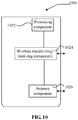
- FIG. 10 is a block diagram of another device suitable for determining correspondence according to an exemplary embodiment.
- a device 1000 may be provided as a base station.
- the device 1000 includes a processing component 1022, a wireless transmitting/receiving component 1024, an antenna component 1026, and a wireless interface-specific signal processing portion.
- the processing component 1022 may further include one or more processors.
- One processor in the processing component 1022 may be configured to:
- non-transitory computer-readable storage medium including instructions.
- the instructions are executable by the processor 1022 of the device 1000 to complete the above described method for indicating correspondence.
- the non-transitory computer-readable storage medium may be a ROM, a RAM, a CD-ROM, a magnetic tape, a floppy disc, an optical data storage device and the like.
- the device embodiments substantially correspond to the method embodiments, and thus related parts refer to part of descriptions of the method embodiments.
- the device embodiments described above are only schematic. Units described as separate parts therein may or may not be physically separated. Parts displayed as units may or may not be physical units, and namely may be located in the same place or may also be distributed to a plurality of network units. Part or all of the modules therein may be selected according to a practical requirement to achieve the purpose of the solutions of the embodiments. Those of ordinary skill in the art may understand and implement without creative work.
Landscapes
- Engineering & Computer Science (AREA)
- Computer Networks & Wireless Communication (AREA)
- Signal Processing (AREA)
- Mobile Radio Communication Systems (AREA)
Applications Claiming Priority (1)
| Application Number | Priority Date | Filing Date | Title |
|---|---|---|---|
| PCT/CN2017/105725 WO2019071470A1 (zh) | 2017-10-11 | 2017-10-11 | 对应关系的指示及确定方法、装置、基站和用户设备 |
Publications (3)
| Publication Number | Publication Date |
|---|---|
| EP3684111A1 true EP3684111A1 (de) | 2020-07-22 |
| EP3684111A4 EP3684111A4 (de) | 2021-05-19 |
| EP3684111B1 EP3684111B1 (de) | 2022-04-13 |
Family
ID=65530622
Family Applications (1)
| Application Number | Title | Priority Date | Filing Date |
|---|---|---|---|
| EP17928296.7A Active EP3684111B1 (de) | 2017-10-11 | 2017-10-11 | Korrespondenzanzeige- und -bestimmungsverfahren, basisstation und benutzergerät |
Country Status (5)
| Country | Link |
|---|---|
| US (1) | US11317394B2 (de) |
| EP (1) | EP3684111B1 (de) |
| CN (1) | CN109451859B (de) |
| ES (1) | ES2921705T3 (de) |
| WO (1) | WO2019071470A1 (de) |
Families Citing this family (1)
| Publication number | Priority date | Publication date | Assignee | Title |
|---|---|---|---|---|
| US11700589B2 (en) * | 2020-06-05 | 2023-07-11 | Qualcomm Incorporated | Synchronization signal block transmissions in non-terrestrial networks |
Family Cites Families (19)
| Publication number | Priority date | Publication date | Assignee | Title |
|---|---|---|---|---|
| JP5279677B2 (ja) * | 2009-10-13 | 2013-09-04 | 株式会社日立製作所 | 無線通信システム、無線基地局装置及び無線通信方法 |
| KR20130028397A (ko) * | 2011-09-09 | 2013-03-19 | 삼성전자주식회사 | 무선 통신 시스템에서 동기 및 시스템 정보 획득을 위한 장치 및 방법 |
| WO2014162568A1 (ja) * | 2013-04-04 | 2014-10-09 | 富士通株式会社 | 移動通信システム、移動局、基地局及びセル検出方法 |
| JP6336728B2 (ja) | 2013-08-20 | 2018-06-06 | 株式会社Nttドコモ | 同期信号送信方法及び基地局装置 |
| US20150139001A1 (en) * | 2013-11-20 | 2015-05-21 | Feng Xue | Method and apparatus for beam identification in multi-antenna systems |
| WO2016203290A1 (en) * | 2015-06-15 | 2016-12-22 | Telefonaktiebolaget Lm Ericsson (Publ) | Variable synchronization block format |
| CN111818631B (zh) | 2016-01-26 | 2021-12-03 | 华为技术有限公司 | 识别同步信息的方法、通信方法和装置、可读存储介质 |
| WO2018053850A1 (zh) * | 2016-09-26 | 2018-03-29 | 北京小米移动软件有限公司 | 数据传输同步方法及装置 |
| CN106455040B (zh) * | 2016-11-30 | 2019-12-10 | 宇龙计算机通信科技(深圳)有限公司 | 一种传输信息的方法、基站及终端 |
| EP3535940B1 (de) * | 2016-12-07 | 2021-07-21 | LG Electronics Inc. | Verfahren und vorrichtung zur konfiguration des steuerkanals für nr in drahtloskommunikationssystem |
| CN106793058B (zh) | 2016-12-30 | 2019-03-05 | 展讯通信(上海)有限公司 | 处理同步信号块的方法、基站及用户设备 |
| US10505773B2 (en) * | 2017-01-17 | 2019-12-10 | Qualcomm Incorporated | Association between synchronization signal beams and reference signal beams |
| EP3577935B1 (de) * | 2017-02-02 | 2022-12-28 | IPLA Holdings Inc. | Vorrichtungen zur übertragung von paging-blöcken in swept-downlink-strahlen |
| WO2018175705A1 (en) * | 2017-03-23 | 2018-09-27 | Intel IP Corporation | Nr (new radio) prach (physical random access channel) configuration and multi-beam operation |
| GB2563454A (en) * | 2017-06-16 | 2018-12-19 | Nec Corp | Communication system |
| CN109413591B (zh) * | 2017-08-11 | 2019-11-19 | 华为技术有限公司 | 一种数据传输方法、装置、系统、网络设备及用户设备 |
| US10763984B2 (en) * | 2017-08-18 | 2020-09-01 | Qualcomm Incorporated | Frequency division multiplexing synchronization signals (SS) for wideband operation |
| WO2019056210A1 (zh) * | 2017-09-20 | 2019-03-28 | 北京小米移动软件有限公司 | 同步块的指示及确定方法、装置、基站、用户设备 |
| WO2019068257A1 (en) * | 2017-10-06 | 2019-04-11 | Fg Innovation Ip Company Limited | SYSTEMS AND METHODS FOR CELL SELECTION (RE) AND CELL PROHIBITION |
-
2017
- 2017-10-11 EP EP17928296.7A patent/EP3684111B1/de active Active
- 2017-10-11 ES ES17928296T patent/ES2921705T3/es active Active
- 2017-10-11 WO PCT/CN2017/105725 patent/WO2019071470A1/zh unknown
- 2017-10-11 US US16/753,290 patent/US11317394B2/en active Active
- 2017-10-11 CN CN201780001691.9A patent/CN109451859B/zh active Active
Also Published As
| Publication number | Publication date |
|---|---|
| US20200305132A1 (en) | 2020-09-24 |
| CN109451859B (zh) | 2022-12-27 |
| EP3684111A4 (de) | 2021-05-19 |
| CN109451859A (zh) | 2019-03-08 |
| ES2921705T3 (es) | 2022-08-30 |
| WO2019071470A1 (zh) | 2019-04-18 |
| EP3684111B1 (de) | 2022-04-13 |
| US11317394B2 (en) | 2022-04-26 |
Similar Documents
| Publication | Publication Date | Title |
|---|---|---|
| EP3709732B1 (de) | Verfahren zur anzeige von periodeninformation für einen gemeinsamen steuerressourcensatz von restlichen schlüsselsysteminformationen | |
| US11469962B2 (en) | Method and apparatus for configuring information of indicating time-frequency position of SSB, and method and apparatus for determining time-frequency position of SSB | |
| US11057853B2 (en) | Methods and apparatus for indicating and determining synchronization block, and base station and user equipment | |
| EP3481107A1 (de) | Systeminformationübertragungsverfahren und -vorrichtung | |
| EP3713327B1 (de) | Verfahren zur anzeige der frequenzdomäneninformation eines gemeinsamen steuerressourcensatzes von verbleibenden minimalen systeminformationen | |
| US11178637B2 (en) | Paging message receiving method and device, and paging configuration method and device | |
| CN108702700B (zh) | 定义小区同步广播块位置的指示、搜索方法及装置和基站 | |
| US11457437B2 (en) | Method and apparatus for configuring information, base station and user equipment | |
| US11284398B2 (en) | Communication link configuration method and device | |
| US20220256497A1 (en) | Methods and apparatuses for receiving paging signaling, and methods and apparatuses for transmitting paging signaling | |
| US11229008B2 (en) | Paging configuration method and device, paging message receiving method and device, and base station | |
| US20200187262A1 (en) | Unmanned aerial vehicle management method and apparatus, and communication connection establishment method and apparatus | |
| US11388652B2 (en) | Method and apparatus for indicating position of cell-defining synchronization signal block and searching for the same, and base station | |
| US11012958B2 (en) | Signal transmission method and signal transmission apparatus | |
| US11218990B2 (en) | Method and apparatus for receiving and sending system information, user equipment and base station | |
| US11160012B2 (en) | Methods and devices for notifying system information modification, and computer-readable storage media | |
| EP3667938A1 (de) | Verfahren und vorrichtungen zur meldung und bestimmung eines optimalen strahls, benutzergerät und basisstation | |
| US11297626B2 (en) | Information indication method and apparatus, base station and user equipment | |
| US11533728B2 (en) | Data transmission method and apparatus on unlicensed frequency band | |
| EP3684111B1 (de) | Korrespondenzanzeige- und -bestimmungsverfahren, basisstation und benutzergerät | |
| US11956755B2 (en) | Method and apparatus for transmitting paging signaling | |
| CN116918370A (zh) | 一种测量方法、装置、设备及存储介质 |
Legal Events
| Date | Code | Title | Description |
|---|---|---|---|
| STAA | Information on the status of an ep patent application or granted ep patent |
Free format text: STATUS: THE INTERNATIONAL PUBLICATION HAS BEEN MADE |
|
| PUAI | Public reference made under article 153(3) epc to a published international application that has entered the european phase |
Free format text: ORIGINAL CODE: 0009012 |
|
| STAA | Information on the status of an ep patent application or granted ep patent |
Free format text: STATUS: REQUEST FOR EXAMINATION WAS MADE |
|
| 17P | Request for examination filed |
Effective date: 20200416 |
|
| AK | Designated contracting states |
Kind code of ref document: A1 Designated state(s): AL AT BE BG CH CY CZ DE DK EE ES FI FR GB GR HR HU IE IS IT LI LT LU LV MC MK MT NL NO PL PT RO RS SE SI SK SM TR |
|
| AX | Request for extension of the european patent |
Extension state: BA ME |
|
| DAV | Request for validation of the european patent (deleted) | ||
| DAX | Request for extension of the european patent (deleted) | ||
| A4 | Supplementary search report drawn up and despatched |
Effective date: 20210415 |
|
| RIC1 | Information provided on ipc code assigned before grant |
Ipc: H04W 56/00 20090101AFI20210409BHEP Ipc: H04B 7/06 20060101ALI20210409BHEP Ipc: H04L 5/00 20060101ALI20210409BHEP |
|
| GRAP | Despatch of communication of intention to grant a patent |
Free format text: ORIGINAL CODE: EPIDOSNIGR1 |
|
| STAA | Information on the status of an ep patent application or granted ep patent |
Free format text: STATUS: GRANT OF PATENT IS INTENDED |
|
| INTG | Intention to grant announced |
Effective date: 20211222 |
|
| GRAS | Grant fee paid |
Free format text: ORIGINAL CODE: EPIDOSNIGR3 |
|
| GRAA | (expected) grant |
Free format text: ORIGINAL CODE: 0009210 |
|
| STAA | Information on the status of an ep patent application or granted ep patent |
Free format text: STATUS: THE PATENT HAS BEEN GRANTED |
|
| AK | Designated contracting states |
Kind code of ref document: B1 Designated state(s): AL AT BE BG CH CY CZ DE DK EE ES FI FR GB GR HR HU IE IS IT LI LT LU LV MC MK MT NL NO PL PT RO RS SE SI SK SM TR |
|
| REG | Reference to a national code |
Ref country code: GB Ref legal event code: FG4D |
|
| REG | Reference to a national code |
Ref country code: CH Ref legal event code: EP |
|
| REG | Reference to a national code |
Ref country code: DE Ref legal event code: R096 Ref document number: 602017056113 Country of ref document: DE |
|
| REG | Reference to a national code |
Ref country code: IE Ref legal event code: FG4D |
|
| REG | Reference to a national code |
Ref country code: AT Ref legal event code: REF Ref document number: 1484382 Country of ref document: AT Kind code of ref document: T Effective date: 20220515 |
|
| REG | Reference to a national code |
Ref country code: NL Ref legal event code: FP |
|
| REG | Reference to a national code |
Ref country code: LT Ref legal event code: MG9D |
|
| REG | Reference to a national code |
Ref country code: ES Ref legal event code: FG2A Ref document number: 2921705 Country of ref document: ES Kind code of ref document: T3 Effective date: 20220830 |
|
| REG | Reference to a national code |
Ref country code: AT Ref legal event code: MK05 Ref document number: 1484382 Country of ref document: AT Kind code of ref document: T Effective date: 20220413 |
|
| PG25 | Lapsed in a contracting state [announced via postgrant information from national office to epo] |
Ref country code: SE Free format text: LAPSE BECAUSE OF FAILURE TO SUBMIT A TRANSLATION OF THE DESCRIPTION OR TO PAY THE FEE WITHIN THE PRESCRIBED TIME-LIMIT Effective date: 20220413 Ref country code: PT Free format text: LAPSE BECAUSE OF FAILURE TO SUBMIT A TRANSLATION OF THE DESCRIPTION OR TO PAY THE FEE WITHIN THE PRESCRIBED TIME-LIMIT Effective date: 20220816 Ref country code: NO Free format text: LAPSE BECAUSE OF FAILURE TO SUBMIT A TRANSLATION OF THE DESCRIPTION OR TO PAY THE FEE WITHIN THE PRESCRIBED TIME-LIMIT Effective date: 20220713 Ref country code: LT Free format text: LAPSE BECAUSE OF FAILURE TO SUBMIT A TRANSLATION OF THE DESCRIPTION OR TO PAY THE FEE WITHIN THE PRESCRIBED TIME-LIMIT Effective date: 20220413 Ref country code: HR Free format text: LAPSE BECAUSE OF FAILURE TO SUBMIT A TRANSLATION OF THE DESCRIPTION OR TO PAY THE FEE WITHIN THE PRESCRIBED TIME-LIMIT Effective date: 20220413 Ref country code: GR Free format text: LAPSE BECAUSE OF FAILURE TO SUBMIT A TRANSLATION OF THE DESCRIPTION OR TO PAY THE FEE WITHIN THE PRESCRIBED TIME-LIMIT Effective date: 20220714 Ref country code: FI Free format text: LAPSE BECAUSE OF FAILURE TO SUBMIT A TRANSLATION OF THE DESCRIPTION OR TO PAY THE FEE WITHIN THE PRESCRIBED TIME-LIMIT Effective date: 20220413 Ref country code: BG Free format text: LAPSE BECAUSE OF FAILURE TO SUBMIT A TRANSLATION OF THE DESCRIPTION OR TO PAY THE FEE WITHIN THE PRESCRIBED TIME-LIMIT Effective date: 20220713 Ref country code: AT Free format text: LAPSE BECAUSE OF FAILURE TO SUBMIT A TRANSLATION OF THE DESCRIPTION OR TO PAY THE FEE WITHIN THE PRESCRIBED TIME-LIMIT Effective date: 20220413 |
|
| PG25 | Lapsed in a contracting state [announced via postgrant information from national office to epo] |
Ref country code: RS Free format text: LAPSE BECAUSE OF FAILURE TO SUBMIT A TRANSLATION OF THE DESCRIPTION OR TO PAY THE FEE WITHIN THE PRESCRIBED TIME-LIMIT Effective date: 20220413 Ref country code: PL Free format text: LAPSE BECAUSE OF FAILURE TO SUBMIT A TRANSLATION OF THE DESCRIPTION OR TO PAY THE FEE WITHIN THE PRESCRIBED TIME-LIMIT Effective date: 20220413 Ref country code: LV Free format text: LAPSE BECAUSE OF FAILURE TO SUBMIT A TRANSLATION OF THE DESCRIPTION OR TO PAY THE FEE WITHIN THE PRESCRIBED TIME-LIMIT Effective date: 20220413 Ref country code: IS Free format text: LAPSE BECAUSE OF FAILURE TO SUBMIT A TRANSLATION OF THE DESCRIPTION OR TO PAY THE FEE WITHIN THE PRESCRIBED TIME-LIMIT Effective date: 20220813 |
|
| REG | Reference to a national code |
Ref country code: DE Ref legal event code: R097 Ref document number: 602017056113 Country of ref document: DE |
|
| PG25 | Lapsed in a contracting state [announced via postgrant information from national office to epo] |
Ref country code: SM Free format text: LAPSE BECAUSE OF FAILURE TO SUBMIT A TRANSLATION OF THE DESCRIPTION OR TO PAY THE FEE WITHIN THE PRESCRIBED TIME-LIMIT Effective date: 20220413 Ref country code: SK Free format text: LAPSE BECAUSE OF FAILURE TO SUBMIT A TRANSLATION OF THE DESCRIPTION OR TO PAY THE FEE WITHIN THE PRESCRIBED TIME-LIMIT Effective date: 20220413 Ref country code: RO Free format text: LAPSE BECAUSE OF FAILURE TO SUBMIT A TRANSLATION OF THE DESCRIPTION OR TO PAY THE FEE WITHIN THE PRESCRIBED TIME-LIMIT Effective date: 20220413 Ref country code: EE Free format text: LAPSE BECAUSE OF FAILURE TO SUBMIT A TRANSLATION OF THE DESCRIPTION OR TO PAY THE FEE WITHIN THE PRESCRIBED TIME-LIMIT Effective date: 20220413 Ref country code: DK Free format text: LAPSE BECAUSE OF FAILURE TO SUBMIT A TRANSLATION OF THE DESCRIPTION OR TO PAY THE FEE WITHIN THE PRESCRIBED TIME-LIMIT Effective date: 20220413 Ref country code: CZ Free format text: LAPSE BECAUSE OF FAILURE TO SUBMIT A TRANSLATION OF THE DESCRIPTION OR TO PAY THE FEE WITHIN THE PRESCRIBED TIME-LIMIT Effective date: 20220413 |
|
| PLBE | No opposition filed within time limit |
Free format text: ORIGINAL CODE: 0009261 |
|
| STAA | Information on the status of an ep patent application or granted ep patent |
Free format text: STATUS: NO OPPOSITION FILED WITHIN TIME LIMIT |
|
| 26N | No opposition filed |
Effective date: 20230116 |
|
| PG25 | Lapsed in a contracting state [announced via postgrant information from national office to epo] |
Ref country code: AL Free format text: LAPSE BECAUSE OF FAILURE TO SUBMIT A TRANSLATION OF THE DESCRIPTION OR TO PAY THE FEE WITHIN THE PRESCRIBED TIME-LIMIT Effective date: 20220413 |
|
| PG25 | Lapsed in a contracting state [announced via postgrant information from national office to epo] |
Ref country code: SI Free format text: LAPSE BECAUSE OF FAILURE TO SUBMIT A TRANSLATION OF THE DESCRIPTION OR TO PAY THE FEE WITHIN THE PRESCRIBED TIME-LIMIT Effective date: 20220413 Ref country code: MC Free format text: LAPSE BECAUSE OF FAILURE TO SUBMIT A TRANSLATION OF THE DESCRIPTION OR TO PAY THE FEE WITHIN THE PRESCRIBED TIME-LIMIT Effective date: 20220413 |
|
| REG | Reference to a national code |
Ref country code: CH Ref legal event code: PL |
|
| REG | Reference to a national code |
Ref country code: BE Ref legal event code: MM Effective date: 20221031 |
|
| P01 | Opt-out of the competence of the unified patent court (upc) registered |
Effective date: 20230523 |
|
| PG25 | Lapsed in a contracting state [announced via postgrant information from national office to epo] |
Ref country code: LU Free format text: LAPSE BECAUSE OF NON-PAYMENT OF DUE FEES Effective date: 20221011 |
|
| PG25 | Lapsed in a contracting state [announced via postgrant information from national office to epo] |
Ref country code: LI Free format text: LAPSE BECAUSE OF NON-PAYMENT OF DUE FEES Effective date: 20221031 Ref country code: CH Free format text: LAPSE BECAUSE OF NON-PAYMENT OF DUE FEES Effective date: 20221031 |
|
| PG25 | Lapsed in a contracting state [announced via postgrant information from national office to epo] |
Ref country code: BE Free format text: LAPSE BECAUSE OF NON-PAYMENT OF DUE FEES Effective date: 20221031 |
|
| PG25 | Lapsed in a contracting state [announced via postgrant information from national office to epo] |
Ref country code: IE Free format text: LAPSE BECAUSE OF NON-PAYMENT OF DUE FEES Effective date: 20221011 |
|
| PGFP | Annual fee paid to national office [announced via postgrant information from national office to epo] |
Ref country code: NL Payment date: 20231019 Year of fee payment: 7 |
|
| PGFP | Annual fee paid to national office [announced via postgrant information from national office to epo] |
Ref country code: GB Payment date: 20231020 Year of fee payment: 7 |
|
| PGFP | Annual fee paid to national office [announced via postgrant information from national office to epo] |
Ref country code: ES Payment date: 20231227 Year of fee payment: 7 |
|
| PG25 | Lapsed in a contracting state [announced via postgrant information from national office to epo] |
Ref country code: IT Free format text: LAPSE BECAUSE OF FAILURE TO SUBMIT A TRANSLATION OF THE DESCRIPTION OR TO PAY THE FEE WITHIN THE PRESCRIBED TIME-LIMIT Effective date: 20220413 |
|
| PGFP | Annual fee paid to national office [announced via postgrant information from national office to epo] |
Ref country code: FR Payment date: 20231026 Year of fee payment: 7 Ref country code: DE Payment date: 20231020 Year of fee payment: 7 |
|
| PG25 | Lapsed in a contracting state [announced via postgrant information from national office to epo] |
Ref country code: HU Free format text: LAPSE BECAUSE OF FAILURE TO SUBMIT A TRANSLATION OF THE DESCRIPTION OR TO PAY THE FEE WITHIN THE PRESCRIBED TIME-LIMIT; INVALID AB INITIO Effective date: 20171011 |
|
| PG25 | Lapsed in a contracting state [announced via postgrant information from national office to epo] |
Ref country code: CY Free format text: LAPSE BECAUSE OF FAILURE TO SUBMIT A TRANSLATION OF THE DESCRIPTION OR TO PAY THE FEE WITHIN THE PRESCRIBED TIME-LIMIT Effective date: 20220413 |