EP3683932A1 - Motor rotor - Google Patents
Motor rotor Download PDFInfo
- Publication number
- EP3683932A1 EP3683932A1 EP20150874.4A EP20150874A EP3683932A1 EP 3683932 A1 EP3683932 A1 EP 3683932A1 EP 20150874 A EP20150874 A EP 20150874A EP 3683932 A1 EP3683932 A1 EP 3683932A1
- Authority
- EP
- European Patent Office
- Prior art keywords
- magnet
- area
- magnetic shielding
- central axis
- shielding component
- Prior art date
- Legal status (The legal status is an assumption and is not a legal conclusion. Google has not performed a legal analysis and makes no representation as to the accuracy of the status listed.)
- Granted
Links
Images



Classifications
-
- H—ELECTRICITY
- H02—GENERATION; CONVERSION OR DISTRIBUTION OF ELECTRIC POWER
- H02K—DYNAMO-ELECTRIC MACHINES
- H02K1/00—Details of the magnetic circuit
- H02K1/06—Details of the magnetic circuit characterised by the shape, form or construction
- H02K1/22—Rotating parts of the magnetic circuit
- H02K1/27—Rotor cores with permanent magnets
- H02K1/2706—Inner rotors
- H02K1/272—Inner rotors the magnetisation axis of the magnets being perpendicular to the rotor axis
- H02K1/274—Inner rotors the magnetisation axis of the magnets being perpendicular to the rotor axis the rotor consisting of two or more circumferentially positioned magnets
- H02K1/2753—Inner rotors the magnetisation axis of the magnets being perpendicular to the rotor axis the rotor consisting of two or more circumferentially positioned magnets the rotor consisting of magnets or groups of magnets arranged with alternating polarity
- H02K1/276—Magnets embedded in the magnetic core, e.g. interior permanent magnets [IPM]
- H02K1/2766—Magnets embedded in the magnetic core, e.g. interior permanent magnets [IPM] having a flux concentration effect
-
- H—ELECTRICITY
- H02—GENERATION; CONVERSION OR DISTRIBUTION OF ELECTRIC POWER
- H02K—DYNAMO-ELECTRIC MACHINES
- H02K1/00—Details of the magnetic circuit
- H02K1/06—Details of the magnetic circuit characterised by the shape, form or construction
- H02K1/22—Rotating parts of the magnetic circuit
- H02K1/27—Rotor cores with permanent magnets
- H02K1/2706—Inner rotors
- H02K1/272—Inner rotors the magnetisation axis of the magnets being perpendicular to the rotor axis
- H02K1/274—Inner rotors the magnetisation axis of the magnets being perpendicular to the rotor axis the rotor consisting of two or more circumferentially positioned magnets
- H02K1/2753—Inner rotors the magnetisation axis of the magnets being perpendicular to the rotor axis the rotor consisting of two or more circumferentially positioned magnets the rotor consisting of magnets or groups of magnets arranged with alternating polarity
- H02K1/276—Magnets embedded in the magnetic core, e.g. interior permanent magnets [IPM]
-
- H—ELECTRICITY
- H02—GENERATION; CONVERSION OR DISTRIBUTION OF ELECTRIC POWER
- H02K—DYNAMO-ELECTRIC MACHINES
- H02K11/00—Structural association of dynamo-electric machines with electric components or with devices for shielding, monitoring or protection
- H02K11/01—Structural association of dynamo-electric machines with electric components or with devices for shielding, monitoring or protection for shielding from electromagnetic fields, i.e. structural association with shields
- H02K11/012—Shields associated with rotating parts, e.g. rotor cores or rotary shafts
Definitions
- the present application relates to a rotor and a manufacturing method.
- the motor includes a rotor in the center and a stator approximately in the shape of a cylinder.
- the rotor may have windings formed by winding wires.
- the design of the rotor which may include windings on the surface or magnets embedded in the rotor, depends on the varieties of the motors.
- One design for a permanent magnet motor is to insert magnets into the rotor in a V shape when viewed from the end surface of the motor. How to make use of the flux generated by the magnets more efficiently is one of the research focuses in improving the motor performance.
- US20170169945 provides a motor with a first magnet and a second magnet embedded in a rotor.
- the first magnet and the second magnet are spaced apart by a gap.
- the gap or bridge area is prone to magnetic leakage.
- nonmagnetic materials are provided to fill the bridge area.
- US8508092 provides a motor rotor, wherein a soft magnetic material 130 is formed around a spindle 110; sintered magnets 120 are embedded into the material 130; and a roughly V-shaped bridge area between the magnets 120 and the ends of the V shape are filled with a nonmagnetic material 140.
- the motor rotor is formed and fixed by using a frame 300.
- the inventor of the present application is aware that the rotor provided in the prior art aiming at reducing magnetic leakage has many designs; nevertheless, there is still room for improvement in structural strength and magnetic flux efficiency. Therefore, it is hoped to provide a rotor design that can reduce magnetic leakage and improve the structural strength of the rotor.
- a motor rotor may comprise a rotor body part, a first magnet and a second magnet embedded into the body part and are axially extended, the first magnet and the second magnet being arranged at an angle and spaced apart by a magnetic shielding component extended axially.
- the first magnet comprises a first surface away from a central axis of the rotor body part and a second surface facing the central axis;
- the second magnet comprises a third surface away from the central axis and a fourth surface facing the central axis, wherein the first surface and the third surface and extension surfaces thereof define a first area of the body part away from the central axis and a second area of the body part close to the central axis, wherein the magnetic shielding component is provided with a first contact surface located within the first area and a second contact surface located within the second area;
- the first contact surface faces the central axis and is in contact with the first area, and the second contact surface faces a periphery of the rotor body part and is in contact with the second area.
- a material of the first magnetic shielding component is integrally formed by a nonmagnetic material.
- the material of the first magnetic shielding component comprises stainless steel.
- the first magnet and the second magnet are generally arranged in a V shape;
- the magnetic shielding component may comprise a base, a head connected with the base and located in the first area, and a tail connected with the base and located in the second area.
- the head of the magnetic shielding component comprises a first contact surface
- the tail comprises a second contact surface.
- a first side of the base of the magnetic shielding component is adjacent to the first magnet, and a second side of the base is adjacent to the second magnet.
- a width of the head of the magnetic shielding component is greater than a width of the base; a width of the tail is greater than the width of the base; and a direction of the width is basically perpendicular to a radial direction of the rotor; and when the rotor is subjected to a centrifugal force during rotation, the first contact surface of the head is in contact with the first area to provide a reaction force opposite to counteract the centrifugal force, so that the head of the magnetic shielding component remains in contact with the first area; and the second area is in contact with the second contact surface of the tail to provide a reaction force to counteract the centrifugal force, so that the tail of the magnetic shielding component remains in contact with the second area.
- the magnetic shielding component is in mirror symmetry relative to a radial line.
- a width of the tail of the magnetic shielding component is greater than the width of the head, wherein the width of the tail is roughly one to two times the width of the head.
- a point at the tail of the magnetic shielding component closest to the central axis does not extend beyond an intersection point of an extension surface of the second surface of the first magnet and the fourth surface of the second magnet.
- the magnetic shielding component further comprises a pair of wings radially located between the head and the tail, and the pair of wings comprising a first side and a second side respectively in contact with the first magnet and the second magnet.
- the first magnet in the cross section perpendicular to the central axis, is provided with a length extending along the first surface and a width perpendicular to the length;
- the second magnet is provided with a length extending along the second surface and a width perpendicular to the length;
- the pair of wings are provided with a length and a width perpendicular to the length; and the width of each wing is smaller than the width of the first magnet and smaller than the width of the second magnet.
- the rotor further comprises a third magnet and a fourth magnet.
- the third magnet and the fourth magnet generally form a V shape and are farther away from the central axis than the first magnet and the second magnet in the radial direction, such that the first magnet, the second magnet, the third magnet, and the fourth magnet form a double V-shaped magnet structure.
- the magnetic shielding component comprises the base, the head connected with the base and located in the first area and the tail connected with the base and located in the second area; the base is provided with a first pair of wings extending from two sides thereof and are respectively adjacent to the first magnet and the second magnet and a second pair of wings extending from the two sides thereof and are respectively adjacent to the third magnet and the fourth magnet.
- a motor rotor may comprise a rotor body part, and the body part comprises a first opening and a second opening axially running therethrough and a third opening, located between the first opening and the second opening, axially running therethrough.
- the first opening is provided with a first end adjacent to the third opening; the second opening is provided with a second end adjacent to the third opening; and in a cross section perpendicular to the central axis of the rotor, the first opening and the second opening being generally arranged in a V shape.
- the rotor body part may further comprise a first pair of magnets consisting of a first magnet and a second magnet respectively embedded into the first opening and the second opening, and a magnetic shielding component embedded into the third opening.
- the magnetic shielding component may comprise a radially extended base, a tail adjacent to the central axis and connected with the base, and a head away from the central axis and connected with the base, wherein an axial outer side surface of the head is spaced apart from the first end of the first opening and the second end of the second opening; an axial outer side surface of the tail is spaced apart from the first end of the first opening and the second end of the second opening; a first side of the base is adjacent to the first end of the first opening and a second side of the base is adjacent to the second end of the second opening.
- the first magnet comprises a first surface away from the central axis and a second surface facing the central axis; and the second magnet comprises a third surface away from the central axis and a fourth surface facing the central axis, wherein the first surface and the third surface and extension surfaces thereof define a first area away from the central axis and a second area adjacent to the central axis; the head of the magnetic shielding component is located in the first area and the tail is located in the second area.
- the first side and the second side of the base of the magnetic shielding component are respectively in contact with the first magnet and the second magnet.
- the magnetic shielding component comprises a first wing and a second wing respectively extending from the base to the first magnet and the second magnet, and ends of the first wing and the second wing are respectively in contact with the first magnet and the second magnet.
- the magnetic shielding component is in mirror symmetry relative to a radial line; a width of the head is greater than a width of the base; a width of the tail is greater than the width of the base; and a direction of the width is basically perpendicular to a radial direction of the rotor; the head is provided with a first contact surface facing the central axis, and the tail is provided with a second contact surface away from the central axis and opposite to the first contact surface; when the rotor is subjected to a centrifugal force during rotation, the first contact surface provides a reaction force to a part of an inner wall of a cavity for accommodating the head in the first area, so that the first area remains in contact with the magnetic shielding component; and a part of an inner wall of a cavity for accommodating the tail in the second area provides a reaction force to the second contact surface, so that the tail of the magnetic shielding component remains in the second area.
- the width of the tail of the first magnetic shielding component is greater than the width of the head.
- the rotor further comprises a third magnet and a fourth magnet;
- the third magnet and the fourth magnet generally form a V shape and are farther away from the central axis than the first magnet and the second magnet in the radial direction, such that the first magnet, the second magnet, the magnet, and the fourth magnet form a double V-shaped magnet structure;
- the magnetic shielding component comprises a first pair of wings extended from two sides of the base and a second pair of wings extended from the two sides of the base; two ends of the first pair of wings are adjacent to the first magnet and the second magnet, and two ends of the second pair of wings are adjacent to the third magnet and the fourth magnet.
- the motor rotor further comprises a second pair, a third pair, a fourth pair, a fifth pair, a sixth pair, a seventh pair, and an eighth pair of magnets arranged, in the same manner as the first magnet and the second magnet, along a circumferential direction of the body part, and a second, a third, a fourth, a fifth, a sixth, a seventh, and an eighth magnetic shielding components identical to the first magnetic shielding component and located in an area from the second pair of magnets to the eight pair of magnets; and the first to the eighth magnetic shielding components are made of a stainless steel material.
- the motor rotor comprises at least two rotor segments superposed in the axial direction, wherein the magnetic shielding component is an integral component configured to run through the at least two rotor segments.
- a bridge area embedded between magnets of a rotor in a V shape is prone to magnetic leakage.
- How to make use of the magnetic flux generated by the magnets more efficiently and reduce the magnetic leakage generated in this area is the problem that the inventor of the present application aims to address.
- the inventor of the present application has noticed that, although to a certain extent the magnetic leakage can be reduced by filling the nonmagnetic conductive material in the magnetic shielding component area in the prior art, the structure strength is weakened.
- the inventor of the present application provides a rotor in one or a plurality of embodiments that can solve at least one problem in the prior art.
- the nonmagnetic magnetic shielding component minimizes the undesirable magnetic leakage.
- the structure strength of the rotor is improved, and the normal operation of the motor can still be guaranteed when the centrifugal force is large at high speed.
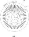
- a motor 100 comprising a rotor part 110 and a stator part 120.
- the stator 120 comprises a plurality of slots 122 arranged in a radial shape and stator windings 124 located in the plurality of slots 122.
- a winding section of the stator windings 124 is rectangular; it is to be understood that stator slots and windings may be arranged in other forms.
- the rotor 110 comprises a rotor body part 112, wherein the body part 112 comprises an opening 221 at the center, a plurality of openings 222 for cooling and the like, and a plurality of pairs of magnets embedded into the body part 112.
- Each pair of magnets may comprise a first magnet 130 and a second magnet 140; and the first magnet 130 and the second magnet 140 are arranged at an angle and spaced apart from each other by a magnetic shielding component 150.
- Such arrangement of each pair of magnets is usually referred to as a V-shaped layout or V-shaped arrangement.
- a delta-shaped permanent magnet arrangement i.e., an arrangement where each group of magnets approximately form a triangle.
- the first magnet 130 and the second magnet 140 are generally extended along the axial direction of the rotor body part 112, i.e., in a direction perpendicular to the plane of FIG. 1 .
- the first magnet 130 and the second magnet 140 generally divide the rotor body part 112 into a part 112C closer to the central axis X and a part 112F far away from the central axis X.
- the first magnet 130 comprises a first surface 131 away from the central axis X of the rotor body part and faces the periphery of the rotor, and a second surface 133 that faces the central axis X.
- the second magnet 140 comprises a third surface 141 away from the central axis X and faces the periphery of the rotor, and a fourth surface 143 that faces the central axis X.
- the meaning of the term “facing" or “away from” the central axis X is not absolute, but rather relative. In other words, as illustrated in the drawing, when any radial line extends from the central axis, point B on the first surface 131 is farther away from the central axis X than point A on the second surface 133, and point D on the third surface 141 is farther away from the central axis X than point C on the fourth surface 143.
- the first surface 131 and the third surface 141 and corresponding extension surfaces 131E and 141E thereof define a first area I, i.e., area 112F, that is far away from the central axis X, and a second area II facing the central axis X, i.e., the area 112C mentioned above.
- a plurality of pairs of magnets 130 and 140 may be arranged as illustrated in the drawing, such that there may exist a plurality of first areas I and second areas II.
- the first areas and second areas located among the plurality of pairs of magnets in the circumferential direction may not be clearly distinguished and defined.
- the second area II may be continuous, i.e., the area 112 C mentioned above.
- One pair of magnets are used as an example to illustrate the relative positions of the first area I and the second area II.
- the magnetic shielding component 150 comprises a head 153 in the first area I, a tail 155 in the second area II, a base 151 connecting the head 153 and the tail 155, and a pair of wings 157 extending to the first magnet 130 and the second magnet 140 as illustrated in the drawings.
- a first side 159a of the wing 157 is adjacent to or in contact with a first end 134 of the first magnet 130; and a second side 159b of the wing 157 is adjacent to or in contact with a second end 136 of the first magnet 130.
- Point TP closest to the central axis X of the tail 155 of the magnetic shielding component 150 coincides with a connecting line crossing point Y of an extension surface 133E of the second surface 133 and an extension surface 143E of the fourth surface 143; or the point TP is farther away from the central axis X than the crossing point Y.
- the magnetic shielding component 150 may be made of a nonmagnetic material, such as, but not limited to, the stainless steel material.
- the magnetic shielding component 150 may prevent the magnetic leakage of the first magnet 130 and the second magnet 140; and on the other hand, it can structurally connect the first area with the second area. More details are provided below.
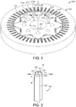
- FIG. 2 illustrates a perspective view of the motor 100 according to embodiment 1, wherein a state in which no magnets and magnetic shielding components are assembled is illustrated.
- the motor 100 may comprise a stator 120 and a rotor 110; and the rotor 110 may be a segment or a part of the whole rotor in the axial direction X.
- the rotor may consist of a plurality of segments. For example, two to six segments may be superposed in the axial direction X.
- the rotor may consist of four segments.
- the rotor may consist of one entire segment. For example, as illustrated in FIG.
- the rotor comprises a plurality of segments, and one segment 110 of the rotor is illustrated in the present embodiment.
- the rotor 110 may comprise a rotor body part 112, and the body part 122 defines a plurality of openings, such as the aforementioned central through holes 221 located at the center, the axially run-through holes 222 for cooling and other purposes, and a plurality of openings for accommodating the first magnet 130, the second magnet 140 and the magnetic shielding component 150.
- a pair of openings are used as an example to illustrate the magnets and the magnetic shielding component of the rotor.
- FIG. 3 illustrates a perspective view of the magnetic shielding component 150.
- the magnetic shielding component 150 comprises the base 151 generally extending radially, the tail 155 close to the central axis X, and the head 153 far away from the central axis X.
- the magnetic shielding component 150 is in mirror symmetry relative to a radial line E of the rotor axis X and the periphery of the rotor. In other words, the magnetic shielding component 150 is in mirror symmetry relative to its centerline.
- the rotor body part 112 comprises a first opening 213 and a second opening 214 axially running therethrough; and the first opening 213 and the second opening 214 are spaced apart by a third opening or a first transition area 215.
- the first opening 213 and the second opening 214 communicate with each other through the third opening 215.
- the first opening 213 is provided with a first end 217 adjacent to the third opening 215, and the second opening 214 is provided with a second end 218 adjacent to the third opening 215.
- the first opening 213 and the second opening 214 are respectively used for the first pair of magnets consisting of the first magnet 130 and the second magnet 140 to be embedded therein.
- the third opening 215 is configured to accommodate the magnetic shielding component 150.
- the first opening 213 and the second opening 214 or i.e., the first magnet 130 and the second magnet 140, are generally arranged in a V shape.
- An outer side surface 156 of the head 153 of the magnetic shielding component 150 along the axial direction is only in contact with the rotor body part 112. That is, the outer side surface 156 of the head 153 in the axial direction is spaced apart from the first end 217 of the first opening 213 and the second end 218 of the second opening 214, and is farther away from the central axis X of the rotor than the first end 217 and the second end 218.
- the head 153 comprises a first contact surface S1 facing the body center X; and the first contact surface S1 may be a part of the outer side surface 156.
- the first contact surface S1 is spaced apart from the first opening 213 and the second opening 214. That is to say, the head 153 of the magnetic shielding component 150 is relatively independent of the first opening 213 and the second opening 214, and the first magnet 130 and the second magnet 140 respectively embedded into the first opening 213 and the second opening 213.
- the motor rotor 112 further comprises a second pair, a third pair, a fourth pair, a fifth pair, a sixth pair, a seventh pair, and an eighth pair of magnets arranged, in the same manner as the first magnet 213 and the second magnet 214, along a circumferential direction of the body part, as well as eight pairs of similar magnets located in the eight pairs of openings.
- the motor rotor 112 comprises a second, a third, a fourth, a fifth, a sixth, a seventh, and an eighth magnetic shielding components identical to the first magnetic shielding component 150, wherein the first to eighth magnetic shielding components may be made of a magnetic shielding material, such as, but not limited to, the stainless steel material.
- the first opening 213 comprises a first inner wall 213a relatively far away from the central axis but faces the central axis, and a second inner wall 213b relatively close to but faces away from the central axis X; as described above, the first magnet 130 comprises the first surface 131 away from the central axis and a second surface 133 facing the central axis.
- the first inner wall 213a is adjacent to the first surface 131 of the first magnet 130; and the gap therebetween can be ignored, which is not described herein.
- the second opening 214 comprises a first inner wall 214a relatively far away from the central axis but faces the central axis, and a second inner wall 214b relatively close to but faces away from the central axis X;
- the first magnet 140 comprises the third surface 141 away from the central axis and the fourth surface 143 facing the central axis.
- the first inner wall 214a is adjacent to the third surface 141 of the second magnet 140; and the gap therebetween can be ignored.
- An extension surface 213E of the first inner wall 213a and an extension surface 214E of the first inner wall 214a, or, the extension surface 131E of the first surface 131 and the extension surface 141E of the third surface, define the first area I away from the central axis and a second area II adjacent to the central axis.
- the head 153 of the magnetic shielding component 150 is located in the first area I, whereas the tail 155 is located in the second area II. Similar to the example illustrated in FIG. 1 , the meaning of the term “facing" or "away from” the central axis X is not absolute, but rather relative.
- first areas I there may exist a plurality of first areas I defined by a plurality of pairs of openings or magnets, as well as second areas II communicated with each other. There is no need to distinguish the first areas from the second areas in the circumferential direction among a plurality of pairs of magnets.
- the first areas and second areas are introduced to mainly describe the relative relationships and the structure and function of the magnetic shielding component.
- the first magnet 130 and the second magnet 140 may similarly be segmented in the axial direction.
- the first magnet and the second magnet may have a size corresponding to the axial length of the rotor segment.
- the magnetic shielding component 150 is preferably not segmented, but instead having a size running through the axial direction of the entire rotor in order to provide a better magnetic shielding effect and structural strength.
- FIG. 4 An enlarged schematic diagram of area H in FIG. 1 is shown. A simple stress analysis of the magnetic shielding component 150 is also provided. Together with the illustration shown in FIGs. 1 to 4 , when the motor rotates at a high speed, the rotor 112 itself, especially the first area I and the magnets 130 and 140, will be subjected to the centrifugal force Fc. The first area being subjected to the centrifugal force Fc is illustrated in the figures.
- air gaps 216 are kept from the ends of the first magnet 130 and the second magnet 140 close to the outer edge of the rotor to the ends of the corresponding first opening 213 and the second opening 214; and a distance between the air gaps and the outer edge/periphery of the rotor is desirably to be as short as possible.
- This configuration might make the first area I, including the magnets, to move away from the central axis during a high-speed rotation.
- the motor provided in the present application can minimize the magnetic leakage on the one hand, and effectively improve the strength on the other by providing the magnetic shielding component that connects the first area I and the second area II.
- the magnetic shielding component 150 in the above embodiment comprises the base 151, the head 153, the tail 155, and the wings 157.
- the base 151 generally extends radially, and the head 153 and the tail 155 have a size larger than that of the base 151.
- a width W1 of the head 153 is greater than the size of the base 151; and the width W2 of the tail 255 is greater than the size of the base 151.
- the head 153 located in the first area I comprises a first contact surface S1
- the tail 155 located in the second area II comprises a second contact surface S2
- the first contact surface S1 and the second contact surface S2 face each other.
- the first contact surface S1 is spaced apart from the first opening 213, the second opening 214, the first magnet 130 in the first opening 213, and the second magnet 140 in the second opening 214.
- the second contact surface S2 may be a part of the outer side surface 158 of the tail 155; and the outer side surface 158 of the tail 155 and the second contact surface S2 may be spaced apart from the first opening 213, the second opening 214, the first magnet 130 in the first opening 213, and the second magnet 140 in the second opening 214.
- the first contact surface S1 of the head 153 of the magnetic shielding component 150 provides a reaction force F1 to a part of the inner wall of a cavity for accommodating the head in the first area I, so that the first area I remains in contact with the magnetic shielding component 150.
- the second contact surface S2 of the tail 155 of the magnetic shielding component 150 is constructed such that, when the rotor rotates and the first area I and the magnetic shielding component 150 are subjected to the centrifugal force, a part of the inner wall of a cavity for accommodating the tail 153 in the second area II provides a reaction force F2 to the second contact surface S2, so that the magnetic shielding component 150 remains in the second area II.
- the structure and size of the magnetic shielding component may be modified based on needs. For example, in one embodiment, the width W1 of the head in the tangential direction T (i.e., the direction perpendicular to the radial direction) is smaller than the width W2 of the tail. In one example, W1 is about 0.5 to 1 times W2.
- the extension directions of the surfaces 131 and 133 of the first magnet 130 and the surfaces 141 and 143 of the second magnet 140 may be referred to as the length directions of the magnets, and the direction perpendicular to the length direction of the magnet in the cross section may be a cross-sectional width J.
- the cross-section width J of the first magnet 130 and the second magnet 140 is greater than a cross-sectional width K of the wings 157 of the magnetic shielding component 150.
- the cross-section width J of the first magnet 130 and the second magnet 140 is at an angle relative to the cross-section width of the wings 157 of the magnetic shielding component 150.
- the cross-sectional width J of the first magnet 130 and the second magnet 140 is substantially in parallel with a direction of the cross-sectional width of the wings 157 of the magnetic shielding component 150.
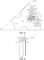
- FIG. 5 illustrates a partial view of a rotor 510 of a motor 500 in the second embodiment of the present application, and specifically shows an arrangement of a pair of magnets and a magnetic shielding component.
- FIG. 6 illustrates a perspective view of the magnetic shielding component in the embodiment.
- the motor comprises a rotor part 510 and a stator part (not shown).
- the rotor 510 comprises a rotor body part 512, and a first magnet 530, a second magnet 540, a third magnet 550, and a fourth magnet 560 embedded into the body part 512.
- Such an arrangement of the magnets is usually referred to as a double V-shaped configuration or double V-shaped arrangement.
- the third magnet 550 and the fourth magnet 560 generally form a V-shape, and are farther away from the central axis X' than the first magnet 530 and the second magnet 540 in the radial direction.
- Magnetic shielding components 570 separate the first magnet 530 from the second magnet 540 and separate the third magnet 550 from the fourth magnet 560.
- the surfaces 551 and 561 of the third magnet 550 and the fourth magnet 560 away from the central axis (or relatively speaking, facing the periphery of the rotor) and the extension surfaces define a first area I facing away from the central axis and a second area II relatively close to the central axis.
- the magnetic shielding component 570 likewise comprises a base 571, a head 573 extending into the first area, a tail 575 extending into the second area, a first pair of wings 577 adjacent to the first magnet 530 and the second magnet 540, and a second pair of wings 579 adjacent to the third magnet 550 and the fourth magnet 560.
- a size of the head 573 and a size of the tail 575 may be larger than that of the base 571; in the tangential direction T', a size of the head 573 may be smaller than that of the tail 575 in the tangential direction.
- the magnetic shielding component may also be designed in other structures based on needs.
- FIGs. 7A-7C possible structure designs for the magnetic shielding components 710, 720, and 730 in the third, the fourth, and the fifth embodiments are shown.
- the magnetic shielding component may have a base, a head, and a tail.
- the width of the head is greater than the width of the base; and the width of the tail is greater than the width of the base.
- the direction of the width is basically perpendicular to the radial direction of the rotor.
- the width direction may also be similar to the tangential direction of the rotor mentioned in the above embodiment.
- the head and/or tail of the magnetic shielding component in different examples may have different designs.
- the head and/or tail may be provided with a triangular cross section, a trapezoidal cross section, a rectangular cross section, etc.
- FIGs. 7A to 7C have the following in common: the head and the tail have opposite contact surfaces or tangential contact surfaces perpendicular to the radial direction.
- the magnetic shielding component 700 comprises a base 751, a head 753, and a tail 755.
- the head 753 and the tail 755 of the magnetic shielding component 700 are respectively located in the first area and the second area of the rotor.
- the head 753 is provided with a tangential first contact surface 711 in the first area and the tail 755 is provided with a tangential second contact surface 712 in the second area.
- the base 751 is provided with a first side 760 and a second side 762.
- the magnetic shielding component 800 comprises a base 851, a head 853, and a tail 855.
- the head 853 and the tail 855 of the magnetic shielding component 800 are respectively located in the first area and the second area of the rotor.
- the head 853 is provided with a tangential first contact surface 811 in the first area and the tail 855 is provided with a tangential second contact surface 812 in the second area.
- the base 851 is provided with a first side 860 and a second side 862.
- the magnetic shielding component 900 comprises a base 951, a head 953, and a tail 955.
- the head 953 and the tail 955 of the magnetic shielding component 900 are respectively located in the first area and the second area of the rotor.
- the head 953 is provided with a tangential first contact surface 911 in the first area and the tail 855 is provided with a tangential second contact surface 912 in the second area.
- the base 951 is provided with a first side 960 and a second side 962.
- the first contact surfaces 711, 811, and 911 of the magnetic shielding components 700, 800, and 900 face the central axis and are in contact with the first area I
- the second contact surfaces 712, 812, and 912 face away the central axis (or face the periphery of the rotor) and are in contact with the second area II.
- the magnetic shielding component when under the effect of the centrifugal force, the magnetic shielding component maintains the connection between the first area and the second area.
- the second area provides a reaction force through the second contact surface so that the magnetic shielding component remains in the second region. That is to say, when under the effect of the centrifugal force, the magnetic shielding component maintains the connection with the second area, thereby maintaining the connection between the first area and the second area.
- the magnetic shielding components illustrated in FIGs 7A, 7B, and 7C do not have wings. Please refer to the examples illustrated in FIGs.
- the design of having a contact surface in contact with the first area and the second area achieves the structural strength of the rotor magnets when combined with the outer peripheral part and the inner peripheral part.
- the first magnet and the second magnet may extend to the base of the magnetic shielding component.
- the first sides 760, 860, and 960 of the bases 751, 851, and 951 are in contact with the first magnet; and the second sides 762, 862, and 962 of the bases 751, 851, and 951 are in contact with the second magnet.
- first sides 760, 860, and 960 of the bases 751, 851, and 951 are adjacent to the first magnet; and the second sides 762, 862, and 962 of the bases 751, 851, and 951 are adjacent to the second magnet.
- the base of the magnetic shielding component may be spaced apart from the first magnet and the second magnet by means of air gaps, thus providing a magnetic shielding effect.
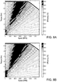
- FIG. 8A shows a relationship among torque, efficiency, and speed of a motor without a magnetic shielding component.
- FIG. 8B shows a relationship among torque, efficiency, and speed of a motor with a magnetic shielding component according to the embodiments illustrated from FIGs. 1 to 4 .
- the x-axis SPEED represents the motor speed (RPM)
- the first y-axis TORQUE on the left side of the drawing represents the torque (Nm);
- the motor efficiency is represented by different shadow areas.
- the bar on the right side of the drawing shows the motor efficiency in the corresponding shadow area.
- the high efficiency area of the motor with the magnetic shielding component in FIG. 8B (the area with efficiency greater than 84%) has been significantly improved.
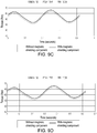
- FIGs. 9A to 9D illustrate comparative diagrams of torque fluctuation curves of the motor according to the first embodiment and the motor without the magnetic shielding component at different speeds.
- FIGs. 9A to 9D illustrate the comparisons of torque of one cycle at speed 1000 rpm, 2000 rpm, 3000 rpm, and 4000 rpm respectively. Other parameters are the same; the peak current is 250 A and the initial current phase angle is 30.
- the torque curve of the motor with the magnetic shielding component is indicated by the solid line
- the torque curve of the motor without the magnetic shielding component is indicated by the dotted line. Under the same conditions, the torque of the motor with the magnetic shielding component is higher than that of the motor without the magnetic shielding component.
- a motor rotor comprising a rotor body part, a first magnet and a second magnet embedded into the body part and are axially extended, and a magnetic shielding component located between the first magnet and the second magnet.
- the present application achieves the magnetic shielding effect on the one hand and the structural strength on the other.
- the simulation results also show that the embodiments in which the magnetic shielding component is used have great efficiency and torque performance.
Landscapes
- Engineering & Computer Science (AREA)
- Power Engineering (AREA)
- Physics & Mathematics (AREA)
- Electromagnetism (AREA)
- Permanent Field Magnets Of Synchronous Machinery (AREA)
Abstract
Description
- The present application relates to a rotor and a manufacturing method.
- Motors have wide application in vehicles and other fields. Typically, the motor includes a rotor in the center and a stator approximately in the shape of a cylinder. The rotor may have windings formed by winding wires. The design of the rotor, which may include windings on the surface or magnets embedded in the rotor, depends on the varieties of the motors. One design for a permanent magnet motor is to insert magnets into the rotor in a V shape when viewed from the end surface of the motor. How to make use of the flux generated by the magnets more efficiently is one of the research focuses in improving the motor performance.
-
US20170169945 provides a motor with a first magnet and a second magnet embedded in a rotor. The first magnet and the second magnet are spaced apart by a gap. The gap or bridge area is prone to magnetic leakage. In order to reduce magnetic leakage, nonmagnetic materials are provided to fill the bridge area. -
US8508092 provides a motor rotor, wherein a softmagnetic material 130 is formed around aspindle 110; sinteredmagnets 120 are embedded into thematerial 130; and a roughly V-shaped bridge area between themagnets 120 and the ends of the V shape are filled with anonmagnetic material 140. In addition, the motor rotor is formed and fixed by using a frame 300. - The inventor of the present application is aware that the rotor provided in the prior art aiming at reducing magnetic leakage has many designs; nevertheless, there is still room for improvement in structural strength and magnetic flux efficiency. Therefore, it is hoped to provide a rotor design that can reduce magnetic leakage and improve the structural strength of the rotor.
- According to one aspect of the present application, a motor rotor is provided. The motor rotor may comprise a rotor body part, a first magnet and a second magnet embedded into the body part and are axially extended, the first magnet and the second magnet being arranged at an angle and spaced apart by a magnetic shielding component extended axially. The first magnet comprises a first surface away from a central axis of the rotor body part and a second surface facing the central axis; the second magnet comprises a third surface away from the central axis and a fourth surface facing the central axis, wherein the first surface and the third surface and extension surfaces thereof define a first area of the body part away from the central axis and a second area of the body part close to the central axis, wherein the magnetic shielding component is provided with a first contact surface located within the first area and a second contact surface located within the second area; the first contact surface faces the central axis and is in contact with the first area, and the second contact surface faces a periphery of the rotor body part and is in contact with the second area.
- According to one embodiment of the present application, a material of the first magnetic shielding component is integrally formed by a nonmagnetic material.
- According to another embodiment of the present application, the material of the first magnetic shielding component comprises stainless steel.
- According to still another embodiment of the present application, in a cross section perpendicular to the central axis, the first magnet and the second magnet are generally arranged in a V shape; the magnetic shielding component may comprise a base, a head connected with the base and located in the first area, and a tail connected with the base and located in the second area. The head of the magnetic shielding component comprises a first contact surface, and the tail comprises a second contact surface. A first side of the base of the magnetic shielding component is adjacent to the first magnet, and a second side of the base is adjacent to the second magnet.
- According to still another embodiment of the present application, a width of the head of the magnetic shielding component is greater than a width of the base; a width of the tail is greater than the width of the base; and a direction of the width is basically perpendicular to a radial direction of the rotor; and when the rotor is subjected to a centrifugal force during rotation, the first contact surface of the head is in contact with the first area to provide a reaction force opposite to counteract the centrifugal force, so that the head of the magnetic shielding component remains in contact with the first area; and the second area is in contact with the second contact surface of the tail to provide a reaction force to counteract the centrifugal force, so that the tail of the magnetic shielding component remains in contact with the second area.
- According to still another embodiment of the present application, the magnetic shielding component is in mirror symmetry relative to a radial line.
- According to still another embodiment of the present application, a width of the tail of the magnetic shielding component is greater than the width of the head, wherein the width of the tail is roughly one to two times the width of the head.
- According to another embodiment of the present application, a point at the tail of the magnetic shielding component closest to the central axis does not extend beyond an intersection point of an extension surface of the second surface of the first magnet and the fourth surface of the second magnet.
- According to still another embodiment of the present application, the magnetic shielding component further comprises a pair of wings radially located between the head and the tail, and the pair of wings comprising a first side and a second side respectively in contact with the first magnet and the second magnet.
- According to still another embodiment of the present application, in the cross section perpendicular to the central axis, the first magnet is provided with a length extending along the first surface and a width perpendicular to the length; the second magnet is provided with a length extending along the second surface and a width perpendicular to the length; the pair of wings are provided with a length and a width perpendicular to the length; and the width of each wing is smaller than the width of the first magnet and smaller than the width of the second magnet.
- According to still another embodiment of the present application, the rotor further comprises a third magnet and a fourth magnet. The third magnet and the fourth magnet generally form a V shape and are farther away from the central axis than the first magnet and the second magnet in the radial direction, such that the first magnet, the second magnet, the third magnet, and the fourth magnet form a double V-shaped magnet structure. The magnetic shielding component comprises the base, the head connected with the base and located in the first area and the tail connected with the base and located in the second area; the base is provided with a first pair of wings extending from two sides thereof and are respectively adjacent to the first magnet and the second magnet and a second pair of wings extending from the two sides thereof and are respectively adjacent to the third magnet and the fourth magnet.
- According to another aspect of the present application, a motor rotor is provided. The motor rotor may comprise a rotor body part, and the body part comprises a first opening and a second opening axially running therethrough and a third opening, located between the first opening and the second opening, axially running therethrough. The first opening is provided with a first end adjacent to the third opening; the second opening is provided with a second end adjacent to the third opening; and in a cross section perpendicular to the central axis of the rotor, the first opening and the second opening being generally arranged in a V shape. The rotor body part may further comprise a first pair of magnets consisting of a first magnet and a second magnet respectively embedded into the first opening and the second opening, and a magnetic shielding component embedded into the third opening. The magnetic shielding component may comprise a radially extended base, a tail adjacent to the central axis and connected with the base, and a head away from the central axis and connected with the base, wherein an axial outer side surface of the head is spaced apart from the first end of the first opening and the second end of the second opening; an axial outer side surface of the tail is spaced apart from the first end of the first opening and the second end of the second opening; a first side of the base is adjacent to the first end of the first opening and a second side of the base is adjacent to the second end of the second opening.
- According to one embodiment of the present application, the first magnet comprises a first surface away from the central axis and a second surface facing the central axis; and the second magnet comprises a third surface away from the central axis and a fourth surface facing the central axis, wherein the first surface and the third surface and extension surfaces thereof define a first area away from the central axis and a second area adjacent to the central axis; the head of the magnetic shielding component is located in the first area and the tail is located in the second area.
- According to another embodiment of the present application, the first side and the second side of the base of the magnetic shielding component are respectively in contact with the first magnet and the second magnet.
- According to still another embodiment of the present application, the magnetic shielding component comprises a first wing and a second wing respectively extending from the base to the first magnet and the second magnet, and ends of the first wing and the second wing are respectively in contact with the first magnet and the second magnet.
- According to still another embodiment of the present application, the magnetic shielding component is in mirror symmetry relative to a radial line; a width of the head is greater than a width of the base; a width of the tail is greater than the width of the base; and a direction of the width is basically perpendicular to a radial direction of the rotor; the head is provided with a first contact surface facing the central axis, and the tail is provided with a second contact surface away from the central axis and opposite to the first contact surface; when the rotor is subjected to a centrifugal force during rotation, the first contact surface provides a reaction force to a part of an inner wall of a cavity for accommodating the head in the first area, so that the first area remains in contact with the magnetic shielding component; and a part of an inner wall of a cavity for accommodating the tail in the second area provides a reaction force to the second contact surface, so that the tail of the magnetic shielding component remains in the second area.
- According to still another embodiment of the present application, the width of the tail of the first magnetic shielding component is greater than the width of the head.
- According to another embodiment of the present application, the rotor further comprises a third magnet and a fourth magnet; the third magnet and the fourth magnet generally form a V shape and are farther away from the central axis than the first magnet and the second magnet in the radial direction, such that the first magnet, the second magnet, the magnet, and the fourth magnet form a double V-shaped magnet structure; the magnetic shielding component comprises a first pair of wings extended from two sides of the base and a second pair of wings extended from the two sides of the base; two ends of the first pair of wings are adjacent to the first magnet and the second magnet, and two ends of the second pair of wings are adjacent to the third magnet and the fourth magnet.
- According to still another embodiment of the present application, the motor rotor further comprises a second pair, a third pair, a fourth pair, a fifth pair, a sixth pair, a seventh pair, and an eighth pair of magnets arranged, in the same manner as the first magnet and the second magnet, along a circumferential direction of the body part, and a second, a third, a fourth, a fifth, a sixth, a seventh, and an eighth magnetic shielding components identical to the first magnetic shielding component and located in an area from the second pair of magnets to the eight pair of magnets; and the first to the eighth magnetic shielding components are made of a stainless steel material.
- According to still another embodiment of the present application, the motor rotor comprises at least two rotor segments superposed in the axial direction, wherein the magnetic shielding component is an integral component configured to run through the at least two rotor segments.
- The above and other advantages and features of the present application will become apparent by merely referring to the following detailed description of embodiments or in combination with the accompanying drawings.
- For a more complete understanding of embodiments of the present application, reference should be made to more detailed description in the accompanying drawings and the embodiments described through examples below. In the drawings:
-
FIG. 1 schematically shows an end view of a motor according to a first embodiment of the present application; -
FIG. 2 schematically shows a partial perspective view of a motor according to the first embodiment of the present application; -
FIG. 3 schematically shows a perspective view of a magnetic shielding component according to the first embodiment of the present application; -
FIG. 4 schematically shows a simple stress analysis of a rotor and a magnetic shielding component in area H according to the first embodiment of the present application; -
FIG. 5 shows a partial schematic view of a rotor and a magnetic shielding component according to a second embodiment of the present application; -
FIG. 6 schematically shows a perspective view of the magnetic shielding component ofFIG. 5 . -
FIGs. 7A to 7C schematically show perspective views of magnetic shielding components according to a third, a fourth, and a fifth embodiments; -
FIGs. 8A and 8B show comparative diagrams of the simulation results of motor speed, torque, and efficiency in the first embodiment; -
FIGs. 9A to 9D show comparative diagrams of torque fluctuation curves of the motor at different speeds in the first embodiment. - For reference numerals in the drawings, the same or similar reference numerals are used to indicate the same or similar components. In the description below, multiple operation parameters and components are described in multiple embodiments. These specific parameters and components are included herein as examples only and are not meant to be limiting.
- Specific embodiments of the present application are disclosed in this description as needed; however, it should be understood that the disclosed embodiments are only examples of the present application and may be implemented in various alternative forms. The drawings do not need to be drawn to scale; some features may be enlarged or shrunk to display details of specific components. Therefore, the specific structures and functional details disclosed herein should not be construed as limiting, but represents a basis for teaching those skilled in the art to implement the present application in many forms.
- As mentioned in the background, in permanent magnet motors, a bridge area embedded between magnets of a rotor in a V shape is prone to magnetic leakage. How to make use of the magnetic flux generated by the magnets more efficiently and reduce the magnetic leakage generated in this area is the problem that the inventor of the present application aims to address. In addition, the inventor of the present application has noticed that, although to a certain extent the magnetic leakage can be reduced by filling the nonmagnetic conductive material in the magnetic shielding component area in the prior art, the structure strength is weakened. Thus, the inventor of the present application provides a rotor in one or a plurality of embodiments that can solve at least one problem in the prior art. On the one hand, the nonmagnetic magnetic shielding component minimizes the undesirable magnetic leakage. On the other hand, through the unique design of the magnetic shielding component, the structure strength of the rotor is improved, and the normal operation of the motor can still be guaranteed when the centrifugal force is large at high speed.
- As illustrated in
FIG. 1 , the end view of themotor 100 is shown. In the embodiment illustrated inFIG. 1 , amotor 100 is illustrated, comprising arotor part 110 and astator part 120. Thestator 120 comprises a plurality ofslots 122 arranged in a radial shape andstator windings 124 located in the plurality ofslots 122. In this embodiment, a winding section of thestator windings 124 is rectangular; it is to be understood that stator slots and windings may be arranged in other forms. Therotor 110 comprises arotor body part 112, wherein thebody part 112 comprises anopening 221 at the center, a plurality ofopenings 222 for cooling and the like, and a plurality of pairs of magnets embedded into thebody part 112. Each pair of magnets may comprise afirst magnet 130 and asecond magnet 140; and thefirst magnet 130 and thesecond magnet 140 are arranged at an angle and spaced apart from each other by amagnetic shielding component 150. Such arrangement of each pair of magnets is usually referred to as a V-shaped layout or V-shaped arrangement. In accordance with the V-shaped arrangement, there further exists a delta-shaped permanent magnet arrangement, i.e., an arrangement where each group of magnets approximately form a triangle. Although the embodiment of the present application is discussed using the V-shaped arrangement, it is to be understood that advantages can be obtained by adopting the solution of the present application. - Please continue to refer to
FIG. 1 . Thefirst magnet 130 and thesecond magnet 140 are generally extended along the axial direction of therotor body part 112, i.e., in a direction perpendicular to the plane ofFIG. 1 . In the end face or the cross section illustrated inFIG. 1 , thefirst magnet 130 and thesecond magnet 140 generally divide therotor body part 112 into apart 112C closer to the central axis X and apart 112F far away from the central axis X. Specifically, thefirst magnet 130 comprises afirst surface 131 away from the central axis X of the rotor body part and faces the periphery of the rotor, and asecond surface 133 that faces the central axis X. Thesecond magnet 140 comprises athird surface 141 away from the central axis X and faces the periphery of the rotor, and afourth surface 143 that faces the central axis X. The meaning of the term "facing" or "away from" the central axis X is not absolute, but rather relative. In other words, as illustrated in the drawing, when any radial line extends from the central axis, point B on thefirst surface 131 is farther away from the central axis X than point A on thesecond surface 133, and point D on thethird surface 141 is farther away from the central axis X than point C on thefourth surface 143. Thefirst surface 131 and thethird surface 141 and corresponding extension surfaces 131E and 141E thereof define a first area I, i.e.,area 112F, that is far away from the central axis X, and a second area II facing the central axis X, i.e., thearea 112C mentioned above. Along the circumferential direction, a plurality of pairs ofmagnets area 112 C mentioned above. One pair of magnets are used as an example to illustrate the relative positions of the first area I and the second area II. - Please continue to refer to
FIG. 1 and further toFIGs. 2-4 . Themagnetic shielding component 150 comprises ahead 153 in the first area I, atail 155 in the second area II, abase 151 connecting thehead 153 and thetail 155, and a pair ofwings 157 extending to thefirst magnet 130 and thesecond magnet 140 as illustrated in the drawings. Afirst side 159a of thewing 157 is adjacent to or in contact with afirst end 134 of thefirst magnet 130; and asecond side 159b of thewing 157 is adjacent to or in contact with asecond end 136 of thefirst magnet 130. Point TP closest to the central axis X of thetail 155 of themagnetic shielding component 150 coincides with a connecting line crossing point Y of anextension surface 133E of thesecond surface 133 and anextension surface 143E of thefourth surface 143; or the point TP is farther away from the central axis X than the crossing point Y. Themagnetic shielding component 150 may be made of a nonmagnetic material, such as, but not limited to, the stainless steel material. On the one hand, themagnetic shielding component 150 may prevent the magnetic leakage of thefirst magnet 130 and thesecond magnet 140; and on the other hand, it can structurally connect the first area with the second area. More details are provided below. -
FIG. 2 illustrates a perspective view of themotor 100 according toembodiment 1, wherein a state in which no magnets and magnetic shielding components are assembled is illustrated. As illustrated inFIG. 2 , themotor 100 may comprise astator 120 and arotor 110; and therotor 110 may be a segment or a part of the whole rotor in the axial direction X. In the axial direction X, the rotor may consist of a plurality of segments. For example, two to six segments may be superposed in the axial direction X. In one embodiment, the rotor may consist of four segments. In other embodiments, the rotor may consist of one entire segment. For example, as illustrated inFIG. 2 , the rotor comprises a plurality of segments, and onesegment 110 of the rotor is illustrated in the present embodiment. Together with the illustration shown inFIG. 1 , therotor 110 may comprise arotor body part 112, and thebody part 122 defines a plurality of openings, such as the aforementioned central throughholes 221 located at the center, the axially run-throughholes 222 for cooling and other purposes, and a plurality of openings for accommodating thefirst magnet 130, thesecond magnet 140 and themagnetic shielding component 150. For the convenience of description, a pair of openings are used as an example to illustrate the magnets and the magnetic shielding component of the rotor. -
FIG. 3 illustrates a perspective view of themagnetic shielding component 150. As described above, themagnetic shielding component 150 comprises the base 151 generally extending radially, thetail 155 close to the central axis X, and thehead 153 far away from the central axis X. Themagnetic shielding component 150 is in mirror symmetry relative to a radial line E of the rotor axis X and the periphery of the rotor. In other words, themagnetic shielding component 150 is in mirror symmetry relative to its centerline. - Together with the illustration shown in
FIGs. 1 to 3 , in the described embodiment, therotor body part 112 comprises afirst opening 213 and asecond opening 214 axially running therethrough; and thefirst opening 213 and thesecond opening 214 are spaced apart by a third opening or afirst transition area 215. In other words, thefirst opening 213 and thesecond opening 214 communicate with each other through thethird opening 215. Thefirst opening 213 is provided with afirst end 217 adjacent to thethird opening 215, and thesecond opening 214 is provided with asecond end 218 adjacent to thethird opening 215. Thefirst opening 213 and thesecond opening 214 are respectively used for the first pair of magnets consisting of thefirst magnet 130 and thesecond magnet 140 to be embedded therein. Thethird opening 215 is configured to accommodate themagnetic shielding component 150. In the end face perpendicular to the central axis X of the rotor, thefirst opening 213 and thesecond opening 214, or i.e., thefirst magnet 130 and thesecond magnet 140, are generally arranged in a V shape. Anouter side surface 156 of thehead 153 of themagnetic shielding component 150 along the axial direction is only in contact with therotor body part 112. That is, theouter side surface 156 of thehead 153 in the axial direction is spaced apart from thefirst end 217 of thefirst opening 213 and thesecond end 218 of thesecond opening 214, and is farther away from the central axis X of the rotor than thefirst end 217 and thesecond end 218. Referring further toFIG. 4 , thehead 153 comprises a first contact surface S1 facing the body center X; and the first contact surface S1 may be a part of theouter side surface 156. In the illustrated embodiment, the first contact surface S1 is spaced apart from thefirst opening 213 and thesecond opening 214. That is to say, thehead 153 of themagnetic shielding component 150 is relatively independent of thefirst opening 213 and thesecond opening 214, and thefirst magnet 130 and thesecond magnet 140 respectively embedded into thefirst opening 213 and thesecond opening 213. Anouter side surface 158 of thetail 155 of themagnetic shielding component 150 is only in contact with therotor body part 112 along the axial direction, and is relatively independent of thefirst opening 213, thesecond opening 214, and thefirst magnet 130 and thesecond magnet 140 respectively embedded into thefirst opening 213 and thesecond opening 214. Similarly, in the illustrated embodiment, themotor rotor 112 further comprises a second pair, a third pair, a fourth pair, a fifth pair, a sixth pair, a seventh pair, and an eighth pair of magnets arranged, in the same manner as thefirst magnet 213 and thesecond magnet 214, along a circumferential direction of the body part, as well as eight pairs of similar magnets located in the eight pairs of openings. Similarly, themotor rotor 112 comprises a second, a third, a fourth, a fifth, a sixth, a seventh, and an eighth magnetic shielding components identical to the firstmagnetic shielding component 150, wherein the first to eighth magnetic shielding components may be made of a magnetic shielding material, such as, but not limited to, the stainless steel material. - Please continue to refer to
FIG. 2 . Thefirst opening 213 comprises a firstinner wall 213a relatively far away from the central axis but faces the central axis, and a secondinner wall 213b relatively close to but faces away from the central axis X; as described above, thefirst magnet 130 comprises thefirst surface 131 away from the central axis and asecond surface 133 facing the central axis. The firstinner wall 213a is adjacent to thefirst surface 131 of thefirst magnet 130; and the gap therebetween can be ignored, which is not described herein. Similarly, thesecond opening 214 comprises a firstinner wall 214a relatively far away from the central axis but faces the central axis, and a secondinner wall 214b relatively close to but faces away from the central axis X; thefirst magnet 140 comprises thethird surface 141 away from the central axis and thefourth surface 143 facing the central axis. The firstinner wall 214a is adjacent to thethird surface 141 of thesecond magnet 140; and the gap therebetween can be ignored. Anextension surface 213E of the firstinner wall 213a and anextension surface 214E of the firstinner wall 214a, or, theextension surface 131E of thefirst surface 131 and theextension surface 141E of the third surface, define the first area I away from the central axis and a second area II adjacent to the central axis. Thehead 153 of themagnetic shielding component 150 is located in the first area I, whereas thetail 155 is located in the second area II. Similar to the example illustrated inFIG. 1 , the meaning of the term "facing" or "away from" the central axis X is not absolute, but rather relative. - In the embodiment illustrated in
FIG. 2 , there may exist a plurality of first areas I defined by a plurality of pairs of openings or magnets, as well as second areas II communicated with each other. There is no need to distinguish the first areas from the second areas in the circumferential direction among a plurality of pairs of magnets. The first areas and second areas are introduced to mainly describe the relative relationships and the structure and function of the magnetic shielding component. In the above-mentioned embodiment in which therotor 112 consists of a plurality of rotor segments separated in the axial direction, thefirst magnet 130 and thesecond magnet 140 may similarly be segmented in the axial direction. In other words, the first magnet and the second magnet may have a size corresponding to the axial length of the rotor segment. In one embodiment, themagnetic shielding component 150 is preferably not segmented, but instead having a size running through the axial direction of the entire rotor in order to provide a better magnetic shielding effect and structural strength. - Please refer to
FIG. 4 . An enlarged schematic diagram of area H inFIG. 1 is shown. A simple stress analysis of themagnetic shielding component 150 is also provided. Together with the illustration shown inFIGs. 1 to 4 , when the motor rotates at a high speed, therotor 112 itself, especially the first area I and themagnets air gaps 216 are kept from the ends of thefirst magnet 130 and thesecond magnet 140 close to the outer edge of the rotor to the ends of the correspondingfirst opening 213 and thesecond opening 214; and a distance between the air gaps and the outer edge/periphery of the rotor is desirably to be as short as possible. This configuration might make the first area I, including the magnets, to move away from the central axis during a high-speed rotation. The motor provided in the present application can minimize the magnetic leakage on the one hand, and effectively improve the strength on the other by providing the magnetic shielding component that connects the first area I and the second area II. - Please continue to refer to
FIG. 4 in combination withFIG. 1-3 . Themagnetic shielding component 150 in the above embodiment comprises thebase 151, thehead 153, thetail 155, and thewings 157. The base 151 generally extends radially, and thehead 153 and thetail 155 have a size larger than that of thebase 151. For example, from the tangential direction T of the circumference, i.e., from the direction perpendicular to the radial direction, a width W1 of thehead 153 is greater than the size of thebase 151; and the width W2 of the tail 255 is greater than the size of thebase 151. Based on the described embodiment, one can see that thehead 153 located in the first area I comprises a first contact surface S1, whereas thetail 155 located in the second area II comprises a second contact surface S2; the first contact surface S1 and the second contact surface S2 face each other. In the described embodiment, the first contact surface S1 is spaced apart from thefirst opening 213, thesecond opening 214, thefirst magnet 130 in thefirst opening 213, and thesecond magnet 140 in thesecond opening 214. Similarly, the second contact surface S2 may be a part of theouter side surface 158 of thetail 155; and theouter side surface 158 of thetail 155 and the second contact surface S2 may be spaced apart from thefirst opening 213, thesecond opening 214, thefirst magnet 130 in thefirst opening 213, and thesecond magnet 140 in thesecond opening 214. - As illustrated in
FIG. 3 , when the rotor rotates and the first area I, thefirst magnet 130, thesecond magnet 140, and themagnetic shielding component 150 are subjected to the centrifugal force Fc, if themagnetic shielding component 150 does not exist, a gap would appear between the first magnet 1130 and thesecond magnet 140, and the first area I tends to move away from the central axis. When themagnetic shielding component 150 is provided, the first contact surface S1 of thehead 153 of themagnetic shielding component 150 provides a reaction force F1 to a part of the inner wall of a cavity for accommodating the head in the first area I, so that the first area I remains in contact with themagnetic shielding component 150. The second contact surface S2 of thetail 155 of themagnetic shielding component 150 is constructed such that, when the rotor rotates and the first area I and themagnetic shielding component 150 are subjected to the centrifugal force, a part of the inner wall of a cavity for accommodating thetail 153 in the second area II provides a reaction force F2 to the second contact surface S2, so that themagnetic shielding component 150 remains in the second area II. The structure and size of the magnetic shielding component may be modified based on needs. For example, in one embodiment, the width W1 of the head in the tangential direction T (i.e., the direction perpendicular to the radial direction) is smaller than the width W2 of the tail. In one example, W1 is about 0.5 to 1 times W2. In another embodiment, the extension directions of thesurfaces first magnet 130 and thesurfaces second magnet 140 may be referred to as the length directions of the magnets, and the direction perpendicular to the length direction of the magnet in the cross section may be a cross-sectional width J. The cross-section width J of thefirst magnet 130 and thesecond magnet 140 is greater than a cross-sectional width K of thewings 157 of themagnetic shielding component 150. In one embodiment, the cross-section width J of thefirst magnet 130 and thesecond magnet 140 is at an angle relative to the cross-section width of thewings 157 of themagnetic shielding component 150. In another embodiment, the cross-sectional width J of thefirst magnet 130 and thesecond magnet 140 is substantially in parallel with a direction of the cross-sectional width of thewings 157 of themagnetic shielding component 150. -
FIG. 5 illustrates a partial view of arotor 510 of amotor 500 in the second embodiment of the present application, and specifically shows an arrangement of a pair of magnets and a magnetic shielding component.FIG. 6 illustrates a perspective view of the magnetic shielding component in the embodiment. Similar to the embodiment illustrated inFIG. 1 , the motor comprises arotor part 510 and a stator part (not shown). Therotor 510 comprises arotor body part 512, and afirst magnet 530, asecond magnet 540, athird magnet 550, and afourth magnet 560 embedded into thebody part 512. Such an arrangement of the magnets is usually referred to as a double V-shaped configuration or double V-shaped arrangement. Specifically, thethird magnet 550 and thefourth magnet 560 generally form a V-shape, and are farther away from the central axis X' than thefirst magnet 530 and thesecond magnet 540 in the radial direction.Magnetic shielding components 570 separate thefirst magnet 530 from thesecond magnet 540 and separate thethird magnet 550 from thefourth magnet 560. Similar to the example illustrated inFIGs. 1-4 above, thesurfaces third magnet 550 and thefourth magnet 560 away from the central axis (or relatively speaking, facing the periphery of the rotor) and the extension surfaces define a first area I facing away from the central axis and a second area II relatively close to the central axis. Themagnetic shielding component 570 likewise comprises abase 571, ahead 573 extending into the first area, atail 575 extending into the second area, a first pair ofwings 577 adjacent to thefirst magnet 530 and thesecond magnet 540, and a second pair ofwings 579 adjacent to thethird magnet 550 and thefourth magnet 560. Likewise, a size of thehead 573 and a size of thetail 575 may be larger than that of thebase 571; in the tangential direction T', a size of thehead 573 may be smaller than that of thetail 575 in the tangential direction. - In the above-mentioned embodiment, different designs of rotors and magnetic shielding components are described. It is to be understood that the magnetic shielding component may also be designed in other structures based on needs. For example, referring to
FIGs. 7A-7C , possible structure designs for themagnetic shielding components 710, 720, and 730 in the third, the fourth, and the fifth embodiments are shown. In other words, the magnetic shielding component may have a base, a head, and a tail. The width of the head is greater than the width of the base; and the width of the tail is greater than the width of the base. The direction of the width is basically perpendicular to the radial direction of the rotor. The width direction may also be similar to the tangential direction of the rotor mentioned in the above embodiment. The head and/or tail of the magnetic shielding component in different examples may have different designs. For example, the head and/or tail may be provided with a triangular cross section, a trapezoidal cross section, a rectangular cross section, etc.FIGs. 7A to 7C have the following in common: the head and the tail have opposite contact surfaces or tangential contact surfaces perpendicular to the radial direction. - As illustrated in
FIG. 7A , the magnetic shielding component 700 comprises abase 751, ahead 753, and atail 755. Thehead 753 and thetail 755 of the magnetic shielding component 700 are respectively located in the first area and the second area of the rotor. Thehead 753 is provided with a tangentialfirst contact surface 711 in the first area and thetail 755 is provided with a tangentialsecond contact surface 712 in the second area. Thebase 751 is provided with afirst side 760 and asecond side 762. - As illustrated in
FIG. 7B , themagnetic shielding component 800 comprises abase 851, ahead 853, and atail 855. Thehead 853 and thetail 855 of themagnetic shielding component 800 are respectively located in the first area and the second area of the rotor. Thehead 853 is provided with a tangentialfirst contact surface 811 in the first area and thetail 855 is provided with a tangentialsecond contact surface 812 in the second area. Thebase 851 is provided with afirst side 860 and asecond side 862. - As illustrated in
FIG. 7C , themagnetic shielding component 900 comprises abase 951, ahead 953, and atail 955. Thehead 953 and thetail 955 of themagnetic shielding component 900 are respectively located in the first area and the second area of the rotor. Thehead 953 is provided with a tangentialfirst contact surface 911 in the first area and thetail 855 is provided with a tangentialsecond contact surface 912 in the second area. Thebase 951 is provided with afirst side 960 and asecond side 962. - Together with the illustration shown in
FIGs. 1 to 4 , the first contact surfaces 711, 811, and 911 of themagnetic shielding components FIGs. 1 and2 , the magnetic shielding components illustrated inFIGs 7A, 7B, and 7C do not have wings. Please refer to the examples illustrated inFIGs. 1-4 above; when the rotor rotates and is subjected to the centrifugal force, the design of having a contact surface in contact with the first area and the second area achieves the structural strength of the rotor magnets when combined with the outer peripheral part and the inner peripheral part. In such an embodiment, the first magnet and the second magnet may extend to the base of the magnetic shielding component. In some embodiments, thefirst sides bases second sides bases first sides bases second sides bases -
FIG. 8A shows a relationship among torque, efficiency, and speed of a motor without a magnetic shielding component.FIG. 8B shows a relationship among torque, efficiency, and speed of a motor with a magnetic shielding component according to the embodiments illustrated fromFIGs. 1 to 4 . The x-axis SPEED represents the motor speed (RPM), the first y-axis TORQUE on the left side of the drawing represents the torque (Nm); and the motor efficiency is represented by different shadow areas. The bar on the right side of the drawing shows the motor efficiency in the corresponding shadow area. Based on the figures, one can see that, compared with the motor efficiency of the motor without the magnetic shielding component, which is a traditional design, inFIG. 8A , the high efficiency area of the motor with the magnetic shielding component inFIG. 8B (the area with efficiency greater than 84%) has been significantly improved. The black triangular area with the darkest shadow, i.e., the area with efficiency greater than 93%, shows a significant improvement in efficiency. -
FIGs. 9A to 9D illustrate comparative diagrams of torque fluctuation curves of the motor according to the first embodiment and the motor without the magnetic shielding component at different speeds.FIGs. 9A to 9D illustrate the comparisons of torque of one cycle atspeed 1000 rpm, 2000 rpm, 3000 rpm, and 4000 rpm respectively. Other parameters are the same; the peak current is 250 A and the initial current phase angle is 30. During the period of torque fluctuation at different speeds, the torque curve of the motor with the magnetic shielding component is indicated by the solid line, and the torque curve of the motor without the magnetic shielding component is indicated by the dotted line. Under the same conditions, the torque of the motor with the magnetic shielding component is higher than that of the motor without the magnetic shielding component. - As illustrated above, in one or a plurality of embodiments, a motor rotor is provided, comprising a rotor body part, a first magnet and a second magnet embedded into the body part and are axially extended, and a magnetic shielding component located between the first magnet and the second magnet. As a result of the special design of the magnetic shielding component, the present application achieves the magnetic shielding effect on the one hand and the structural strength on the other. The simulation results also show that the embodiments in which the magnetic shielding component is used have great efficiency and torque performance. Various changes, modifications, and alterations can be made by those skilled in the art to these specific embodiments without departing from the essence and scope defined in the claims of the present application.
- The following numbered statements form part of the present disclosure:
-
Statement 1. A motor rotor, comprising:- a rotor body part,
- a first magnet and a second magnet embedded into the body part and are axially extended, the first magnet and the second magnet being arranged at an angle and spaced apart by a magnetic shielding component extended axially, the first magnet comprising a first surface away from a central axis of the rotor body part and a second surface facing the central axis, the second magnet comprising a third surface away from the central axis and a fourth surface facing the central axis, wherein the first surface and the third surface and extension surfaces thereof define a first area of the body part away from the central axis and a second area of the body part close to the central axis, wherein the magnetic shielding component is provided with a first contact surface located within the first area and a second contact surface located within the second area; the first contact surface faces the central axis and is in contact with the first area, and the second contact surface faces a periphery of the rotor body part and is in contact with the second area.
-
Statement 2. The motor rotor according tostatement 1, wherein a material of the first magnetic shielding component is integrally formed by a nonmagnetic material. -
Statement 3. The motor rotor according tostatement 2, wherein the material of the first magnetic shielding component comprises stainless steel. - Statement 4. The motor rotor according to any of the preceding statements, wherein in a cross section perpendicular to the central axis, the first magnet and the second magnet are generally arranged in a V shape; the magnetic shielding component comprises a base, a head connected with the base and located in the first area, and a tail connected with the base and located in the second area; the head comprises the first contact surface, and the tail comprises the second contact surface; a first side of the base is adjacent to the first magnet, and a second side of the base is adjacent to the second magnet.
- Statement 5. The motor rotor according to statement 4, wherein a width of the head is greater than a width of the base; a width of the tail is greater than the width of the base; and a direction of the width is basically perpendicular to a radial direction of the rotor; and when the rotor is subjected to a centrifugal force during rotation, the first contact surface of the head is in contact with the first area to provide a reaction force opposite to counteract the centrifugal force, so that the head of the magnetic shielding component remains in contact with the first area; and the second area is in contact with the second contact surface of the tail to provide a reaction force to counteract the centrifugal force, so that the tail of the magnetic shielding component remains in contact with the second area.
- Statement 6. The motor rotor according to statement 5, wherein the magnetic shielding component is in mirror symmetry relative to a radial line.
- Statement 7. The motor rotor according to statement 6, wherein a width of the tail of the magnetic shielding component is greater than the width of the head, wherein the width of the tail is roughly one to two times the width of the head.
- Statement 8. The motor rotor according to statement 6 or 7, wherein a point at the tail of the magnetic shielding component closest to the central axis does not extend beyond an intersection point of an extension surface of the second surface of the first magnet and the fourth surface of the second magnet.
- Statement 9. The motor rotor according to any of statements 6 to 8, wherein the magnetic shielding component further comprises a pair of wings radially located between the head and the tail, and the pair of wings comprising a first side and a second side respectively in contact with the first magnet and the second magnet.
-
Statement 10. The motor rotor according to statement 9, wherein in the cross section perpendicular to the central axis, the first magnet is provided with a length extending along the first surface and a width perpendicular to the length; the second magnet is provided with a length extending along the second surface and a width perpendicular to the length; the pair of wings are provided with a length and a width perpendicular to the length; and the width of each wing is smaller than the width of the first magnet and smaller than the width of the second magnet. Statement 11. The motor rotor according to any of the preceding statements, wherein the rotor further comprises a third magnet and a fourth magnet; the third magnet and the fourth magnet generally form a V shape and are farther away from the central axis than the first magnet and the second magnet in the radial direction, such that the first magnet, the second magnet, the third magnet, and the fourth magnet form a double V-shaped magnet structure; the magnetic shielding component comprises the base, the head connected with the base and located in the first area and the tail connected with the base and located in the second area; the base is provided with a first pair of wings extending from two sides thereof and are respectively adjacent to the first magnet and the second magnet and a second pair of wings extending from the two sides thereof and are respectively adjacent to the third magnet and the fourth magnet. - Statement 12. A motor rotor, comprising:
- a rotor body part, the body part comprising a first opening and a second opening axially running therethrough and a third opening, located between the first opening and the second opening, axially running therethrough; the first opening is provided with a first end adjacent to the third opening; the second opening is provided with a second end adjacent to the third opening; and in a cross section perpendicular to the central axis of the rotor, the first opening and the second opening being generally arranged in a V shape;
- a first pair of magnets consisting of a first magnet and a second magnet respectively embedded into the first opening and the second opening, and a magnetic shielding component embedded into the third opening, wherein the magnetic shielding component comprises a radially extended base, a tail adjacent to the central axis and connected with the base, and a head away from the central axis and connected with the base, wherein an axial outer side surface of the head is spaced apart from the first end of the first opening and the second end of the second opening; an axial outer side surface of the tail is spaced apart from the first end of the first opening and the second end of the second opening; a first side of the base is adjacent to the first end of the first opening and a second side of the base is adjacent to the second end of the second opening.
- Statement 13. The motor rotor according to statement 12, wherein the first magnet comprises a first surface away from the central axis and a second surface facing the central axis; and the second magnet comprises a third surface away from the central axis and a fourth surface facing the central axis, wherein the first surface and the third surface and extension surfaces thereof define a first area away from the central axis and a second area adjacent to the central axis; the head of the magnetic shielding component is located in the first area and the tail is located in the second area.
- Statement 14. The motor rotor according to statement 12 or 13, wherein the first side and the second side of the base of the magnetic shielding component are respectively in contact with the first magnet and the second magnet.
- Statement 15. The motor rotor according to any of statements 12 to 14, wherein the magnetic shielding component comprises a first wing and a second wing respectively extending from the base to the first magnet and the second magnet, and ends of the first wing and the second wing are respectively in contact with the first magnet and the second magnet.
- Statement 16. The motor rotor according to any of statements 12 to 15, wherein the magnetic shielding component is in mirror symmetry relative to a radial line; a width of the head is greater than a width of the base; a width of the tail is greater than the width of the base; and a direction of the width is basically perpendicular to a radial direction of the rotor; the head is provided with a first contact surface facing the central axis, and the tail is provided with a second contact surface away from the central axis and opposite to the first contact surface; when the rotor is subjected to a centrifugal force during rotation, the first contact surface provides a reaction force to a part of an inner wall of a cavity for accommodating the head in the first area, so that the first area remains in contact with the magnetic shielding component; and a part of an inner wall of a cavity for accommodating the tail in the second area provides a reaction force to the second contact surface, so that the tail of the magnetic shielding component remains in the second area.
- Statement 17. The motor rotor according to statement 16, wherein the width of the tail of the first magnetic shielding component is greater than the width of the head.
- Statement 18. The motor rotor according to any of statements 12 to 17, wherein the rotor further comprises a third magnet and a fourth magnet; the third magnet and the fourth magnet generally form a V shape and are farther away from the central axis than the first magnet and the second magnet in the radial direction, such that the first magnet, the second magnet, the magnet, and the fourth magnet form a double V-shaped magnet structure; the magnetic shielding component comprises a first pair of wings extended from two sides of the base and a second pair of wings extended from the two sides of the base; two ends of the first pair of wings are adjacent to the first magnet and the second magnet, and two ends of the second pair of wings are adjacent to the third magnet and the fourth magnet.
- Statement 19. The motor rotor according to any of statements 12 to 18, wherein the motor rotor further comprises a second pair, a third pair, a fourth pair, a fifth pair, a sixth pair, a seventh pair, and an eighth pair of magnets arranged, in the same manner as the first magnet and the second magnet, along a circumferential direction of the body part, and a second, a third, a fourth, a fifth, a sixth, a seventh, and an eighth magnetic shielding components identical to the first magnetic shielding component and located in an area from the second pair of magnets to the eight pair of magnets; and the first to the eighth magnetic shielding components are made of a stainless steel material.
-
Statement 20. The motor rotor according to any of statements 12 to 19, wherein the motor rotor comprises at least two rotor segments superposed in the axial direction, wherein the magnetic shielding component is an integral component configured to run through the at least two rotor segments. - The claims particularly point out specific combinations and sub-combinations that are considered novel and not obvious. These claims may involve "an" element or "a first" element or similar features. Such claims should be understood as including one or a plurality of such elements, where two or a plurality of such elements are neither required nor excluded. Other combinations and sub-combinations of features, functions, elements, and/or properties described may be claimed through amendment of the current claims or presentation of new claims in the present application or a related application. Such claims, whether broader or narrower than, equivalent to, or different from the original claims, should be regarded as included within the subject matter of the present application.
Claims (11)
- A motor rotor, comprising:a rotor body part,a first magnet and a second magnet embedded into the body part and are axially extended, the first magnet and the second magnet being arranged at an angle and spaced apart by a magnetic shielding component extended axially, the first magnet comprising a first surface away from a central axis of the rotor body part and a second surface facing the central axis, the second magnet comprising a third surface away from the central axis and a fourth surface facing the central axis, wherein the first surface and the third surface and extension surfaces thereof define a first area of the body part away from the central axis and a second area of the body part close to the central axis, wherein the magnetic shielding component is provided with a first contact surface located within the first area and a second contact surface located within the second area; the first contact surface faces the central axis and is in contact with the first area, and the second contact surface faces a periphery of the rotor body part and is in contact with the second area.
- The motor rotor according to claim 1, wherein a material of the first magnetic shielding component is integrally formed by a nonmagnetic material.
- The motor rotor according to claim 2, wherein the material of the first magnetic shielding component comprises stainless steel.
- The motor rotor according to any of the preceding claims, wherein in a cross section perpendicular to the central axis, the first magnet and the second magnet are generally arranged in a V shape; the magnetic shielding component comprises a base, a head connected with the base and located in the first area, and a tail connected with the base and located in the second area; the head comprises the first contact surface, and the tail comprises the second contact surface; a first side of the base is adjacent to the first magnet, and a second side of the base is adjacent to the second magnet.
- The motor rotor according to claim 4, wherein a width of the head is greater than a width of the base; a width of the tail is greater than the width of the base; and a direction of the width is basically perpendicular to a radial direction of the rotor; and when the rotor is subjected to a centrifugal force during rotation, the first contact surface of the head is in contact with the first area to provide a reaction force opposite to counteract the centrifugal force, so that the head of the magnetic shielding component remains in contact with the first area; and the second area is in contact with the second contact surface of the tail to provide a reaction force to counteract the centrifugal force, so that the tail of the magnetic shielding component remains in contact with the second area.
- The motor rotor according to claim 5, wherein the magnetic shielding component is in mirror symmetry relative to a radial line.
- The motor rotor according to claim 6, wherein a width of the tail of the magnetic shielding component is greater than the width of the head, wherein the width of the tail is roughly one to two times the width of the head.
- The motor rotor according to claim 6 or 7, wherein a point at the tail of the magnetic shielding component closest to the central axis does not extend beyond an intersection point of an extension surface of the second surface of the first magnet and the fourth surface of the second magnet.
- The motor rotor according to any of claims 6 to 8, wherein the magnetic shielding component further comprises a pair of wings radially located between the head and the tail, and the pair of wings comprising a first side and a second side respectively in contact with the first magnet and the second magnet.
- The motor rotor according to claim 9, wherein in the cross section perpendicular to the central axis, the first magnet is provided with a length extending along the first surface and a width perpendicular to the length; the second magnet is provided with a length extending along the second surface and a width perpendicular to the length; the pair of wings are provided with a length and a width perpendicular to the length; and the width of each wing is smaller than the width of the first magnet and smaller than the width of the second magnet.
- The motor rotor according to any of the preceding claims, wherein the rotor further comprises a third magnet and a fourth magnet; the third magnet and the fourth magnet generally form a V shape and are farther away from the central axis than the first magnet and the second magnet in the radial direction, such that the first magnet, the second magnet, the third magnet, and the fourth magnet form a double V-shaped magnet structure; the magnetic shielding component comprises the base, the head connected with the base and located in the first area and the tail connected with the base and located in the second area; the base is provided with a first pair of wings extending from two sides thereof and are respectively adjacent to the first magnet and the second magnet and a second pair of wings extending from the two sides thereof and are respectively adjacent to the third magnet and the fourth magnet.
Applications Claiming Priority (1)
| Application Number | Priority Date | Filing Date | Title |
|---|---|---|---|
| CN201910047304.6A CN111463936A (en) | 2019-01-18 | 2019-01-18 | a motor rotor |
Publications (2)
| Publication Number | Publication Date |
|---|---|
| EP3683932A1 true EP3683932A1 (en) | 2020-07-22 |
| EP3683932B1 EP3683932B1 (en) | 2022-12-28 |
Family
ID=69156282
Family Applications (1)
| Application Number | Title | Priority Date | Filing Date |
|---|---|---|---|
| EP20150874.4A Active EP3683932B1 (en) | 2019-01-18 | 2020-01-09 | Motor rotor |
Country Status (3)
| Country | Link |
|---|---|
| US (1) | US11362553B2 (en) |
| EP (1) | EP3683932B1 (en) |
| CN (2) | CN111463936A (en) |
Families Citing this family (4)
| Publication number | Priority date | Publication date | Assignee | Title |
|---|---|---|---|---|
| CN111711294B (en) * | 2020-07-24 | 2025-06-10 | 珠海格力节能环保制冷技术研究中心有限公司 | Rotor structure, motor and compressor |
| US11545860B2 (en) * | 2021-02-22 | 2023-01-03 | GM Global Technology Operations LLC | Inserts for motor rotor core |
| US12155266B2 (en) * | 2021-11-30 | 2024-11-26 | GM Global Technology Operations LLC | Bridgeless and webless rotor assembly using polymer composites |
| US12614935B2 (en) * | 2023-08-11 | 2026-04-28 | Ford Global Technologies, Llc | Electric machine rotor |
Citations (5)
| Publication number | Priority date | Publication date | Assignee | Title |
|---|---|---|---|---|
| WO2011122996A1 (en) * | 2010-03-30 | 2011-10-06 | Volvo Technology Corporation | Rotor of an electric machine with embedded permanent magnets and electric machine |
| US20130026871A1 (en) * | 2011-07-29 | 2013-01-31 | General Electric Company | Electrical machine |
| US8508092B2 (en) | 2010-11-19 | 2013-08-13 | Toyota Motor Engineering & Manufacturing North America, Inc. | Permanent magnet rotors and methods of manufacturing the same |
| US20170169945A1 (en) | 2015-12-10 | 2017-06-15 | Rolls-Royce Plc | Method of manufacturing a magnetically graded material |
| DE102017205858A1 (en) * | 2017-04-06 | 2018-04-19 | Magna powertrain gmbh & co kg | Rotor for a permanent magnet synchronous machine and method of manufacturing such a rotor |
Family Cites Families (9)
| Publication number | Priority date | Publication date | Assignee | Title |
|---|---|---|---|---|
| US7479723B2 (en) | 2007-01-30 | 2009-01-20 | Gm Global Technology Operations, Inc. | Permanent magnet machine rotor |
| WO2011132250A1 (en) | 2010-04-19 | 2011-10-27 | トヨタ自動車株式会社 | Rotor for an embedded-magnet synchronous motor |
| JP5835928B2 (en) * | 2011-04-15 | 2015-12-24 | 三菱重工業株式会社 | Electric motor and electric compressor using the same |
| JP5991545B2 (en) * | 2013-11-15 | 2016-09-14 | 株式会社デンソー | Rotating electric machine rotor and rotating electric machine equipped with the rotor |
| JP6098614B2 (en) * | 2014-11-05 | 2017-03-22 | トヨタ自動車株式会社 | Manufacturing method of rotor |
| JP6137121B2 (en) | 2014-11-07 | 2017-05-31 | トヨタ自動車株式会社 | Rotor structure and rotor manufacturing method |
| DE112016003500B4 (en) | 2016-03-16 | 2024-08-22 | Fuji Electric Co., Ltd. | THREE-PHASE ELECTRIC MACHINE WITH PERMANENT MAGNET AND MANUFACTURING METHOD THEREOF |
| US20180287439A1 (en) | 2017-03-29 | 2018-10-04 | Ford Global Technologies, Llc | Permanent magnet electric machine |
| JP6606157B2 (en) * | 2017-11-15 | 2019-11-13 | ファナック株式会社 | Rotor and rotating electric machine |
-
2019
- 2019-01-18 CN CN201910047304.6A patent/CN111463936A/en not_active Withdrawn
- 2019-01-18 CN CN202510361149.0A patent/CN120200395A/en active Pending
-
2020
- 2020-01-09 EP EP20150874.4A patent/EP3683932B1/en active Active
- 2020-01-10 US US16/739,500 patent/US11362553B2/en active Active
Patent Citations (5)
| Publication number | Priority date | Publication date | Assignee | Title |
|---|---|---|---|---|
| WO2011122996A1 (en) * | 2010-03-30 | 2011-10-06 | Volvo Technology Corporation | Rotor of an electric machine with embedded permanent magnets and electric machine |
| US8508092B2 (en) | 2010-11-19 | 2013-08-13 | Toyota Motor Engineering & Manufacturing North America, Inc. | Permanent magnet rotors and methods of manufacturing the same |
| US20130026871A1 (en) * | 2011-07-29 | 2013-01-31 | General Electric Company | Electrical machine |
| US20170169945A1 (en) | 2015-12-10 | 2017-06-15 | Rolls-Royce Plc | Method of manufacturing a magnetically graded material |
| DE102017205858A1 (en) * | 2017-04-06 | 2018-04-19 | Magna powertrain gmbh & co kg | Rotor for a permanent magnet synchronous machine and method of manufacturing such a rotor |
Also Published As
| Publication number | Publication date |
|---|---|
| US20200235642A1 (en) | 2020-07-23 |
| CN111463936A (en) | 2020-07-28 |
| EP3683932B1 (en) | 2022-12-28 |
| CN120200395A (en) | 2025-06-24 |
| US11362553B2 (en) | 2022-06-14 |
Similar Documents
| Publication | Publication Date | Title |
|---|---|---|
| EP3683932B1 (en) | Motor rotor | |
| JP7339969B2 (en) | Rotor assembly and secondary pole motor | |
| US9496758B2 (en) | Rotor for rotating electric machine | |
| US8957561B2 (en) | Rotor for rotary electric machine | |
| US9065314B2 (en) | Rotor of buried magnet-type electric motor, motor and machine tool having the rotor | |
| US20120074805A1 (en) | Rotor | |
| WO2021205713A1 (en) | Rotating electric machine | |
| WO2023240970A1 (en) | Motor rotor, motor, and electric vehicle | |
| JP6773244B2 (en) | Rotor and rotary electromechanical | |
| KR100256188B1 (en) | 2N pole claw rotor | |
| JP3517319B2 (en) | Synchronous motor rotor | |
| JP6390647B2 (en) | Permanent magnet rotating electric machine | |
| US11863019B2 (en) | Rotor lamination, rotor laminated core, rotor, electric machine, and vehicle | |
| JP7643269B2 (en) | Rotor | |
| JP2023098697A (en) | rotor and motor | |
| CA2774303C (en) | Magnet shaping in permanent magnet synchronous machines | |
| US10886802B2 (en) | Rotor for an electric machine | |
| JP3230225U (en) | Rotor of compressor motor | |
| JP2017216846A (en) | Permanent magnet rotating electric machine | |
| JP2020178434A (en) | Rotor of electric motor and electric motor | |
| JP7754046B2 (en) | Rotor for rotating electrical machine | |
| CN112039236A (en) | Axial rotor of axial gap type rotating electrical machine | |
| WO2020243882A1 (en) | Axial rotor of axial-gap-type rotary electric motor | |
| CN212486223U (en) | Rotor and motor | |
| EP4668544A1 (en) | Rotating electric machine rotor |
Legal Events
| Date | Code | Title | Description |
|---|---|---|---|
| PUAI | Public reference made under article 153(3) epc to a published international application that has entered the european phase |
Free format text: ORIGINAL CODE: 0009012 |
|
| STAA | Information on the status of an ep patent application or granted ep patent |
Free format text: STATUS: THE APPLICATION HAS BEEN PUBLISHED |
|
| AK | Designated contracting states |
Kind code of ref document: A1 Designated state(s): AL AT BE BG CH CY CZ DE DK EE ES FI FR GB GR HR HU IE IS IT LI LT LU LV MC MK MT NL NO PL PT RO RS SE SI SK SM TR |
|
| AX | Request for extension of the european patent |
Extension state: BA ME |
|
| STAA | Information on the status of an ep patent application or granted ep patent |
Free format text: STATUS: REQUEST FOR EXAMINATION WAS MADE |
|
| 17P | Request for examination filed |
Effective date: 20201113 |
|
| RBV | Designated contracting states (corrected) |
Designated state(s): AL AT BE BG CH CY CZ DE DK EE ES FI FR GB GR HR HU IE IS IT LI LT LU LV MC MK MT NL NO PL PT RO RS SE SI SK SM TR |
|
| STAA | Information on the status of an ep patent application or granted ep patent |
Free format text: STATUS: EXAMINATION IS IN PROGRESS |
|
| 17Q | First examination report despatched |
Effective date: 20210330 |
|
| REG | Reference to a national code |
Ref country code: DE Ref legal event code: R079 Ref document number: 602020007124 Country of ref document: DE Free format text: PREVIOUS MAIN CLASS: H02K0001270000 Ipc: H02K0001276000 |
|
| RIC1 | Information provided on ipc code assigned before grant |
Ipc: H02K 11/01 20160101ALI20220503BHEP Ipc: H02K 1/276 20220101AFI20220503BHEP |
|
| GRAP | Despatch of communication of intention to grant a patent |
Free format text: ORIGINAL CODE: EPIDOSNIGR1 |
|
| STAA | Information on the status of an ep patent application or granted ep patent |
Free format text: STATUS: GRANT OF PATENT IS INTENDED |
|
| INTG | Intention to grant announced |
Effective date: 20220725 |
|
| GRAS | Grant fee paid |
Free format text: ORIGINAL CODE: EPIDOSNIGR3 |
|
| GRAA | (expected) grant |
Free format text: ORIGINAL CODE: 0009210 |
|
| STAA | Information on the status of an ep patent application or granted ep patent |
Free format text: STATUS: THE PATENT HAS BEEN GRANTED |
|
| AK | Designated contracting states |
Kind code of ref document: B1 Designated state(s): AL AT BE BG CH CY CZ DE DK EE ES FI FR GB GR HR HU IE IS IT LI LT LU LV MC MK MT NL NO PL PT RO RS SE SI SK SM TR |
|
| REG | Reference to a national code |
Ref country code: GB Ref legal event code: FG4D |
|
| REG | Reference to a national code |
Ref country code: CH Ref legal event code: EP |
|
| REG | Reference to a national code |
Ref country code: DE Ref legal event code: R096 Ref document number: 602020007124 Country of ref document: DE |
|
| REG | Reference to a national code |
Ref country code: AT Ref legal event code: REF Ref document number: 1541081 Country of ref document: AT Kind code of ref document: T Effective date: 20230115 |
|
| REG | Reference to a national code |
Ref country code: IE Ref legal event code: FG4D |
|
| REG | Reference to a national code |
Ref country code: LT Ref legal event code: MG9D |
|
| PG25 | Lapsed in a contracting state [announced via postgrant information from national office to epo] |
Ref country code: SE Free format text: LAPSE BECAUSE OF FAILURE TO SUBMIT A TRANSLATION OF THE DESCRIPTION OR TO PAY THE FEE WITHIN THE PRESCRIBED TIME-LIMIT Effective date: 20221228 Ref country code: NO Free format text: LAPSE BECAUSE OF FAILURE TO SUBMIT A TRANSLATION OF THE DESCRIPTION OR TO PAY THE FEE WITHIN THE PRESCRIBED TIME-LIMIT Effective date: 20230328 Ref country code: LT Free format text: LAPSE BECAUSE OF FAILURE TO SUBMIT A TRANSLATION OF THE DESCRIPTION OR TO PAY THE FEE WITHIN THE PRESCRIBED TIME-LIMIT Effective date: 20221228 Ref country code: FI Free format text: LAPSE BECAUSE OF FAILURE TO SUBMIT A TRANSLATION OF THE DESCRIPTION OR TO PAY THE FEE WITHIN THE PRESCRIBED TIME-LIMIT Effective date: 20221228 |
|
| REG | Reference to a national code |
Ref country code: NL Ref legal event code: MP Effective date: 20221228 |
|
| REG | Reference to a national code |
Ref country code: AT Ref legal event code: MK05 Ref document number: 1541081 Country of ref document: AT Kind code of ref document: T Effective date: 20221228 |
|
| PG25 | Lapsed in a contracting state [announced via postgrant information from national office to epo] |
Ref country code: RS Free format text: LAPSE BECAUSE OF FAILURE TO SUBMIT A TRANSLATION OF THE DESCRIPTION OR TO PAY THE FEE WITHIN THE PRESCRIBED TIME-LIMIT Effective date: 20221228 Ref country code: LV Free format text: LAPSE BECAUSE OF FAILURE TO SUBMIT A TRANSLATION OF THE DESCRIPTION OR TO PAY THE FEE WITHIN THE PRESCRIBED TIME-LIMIT Effective date: 20221228 Ref country code: HR Free format text: LAPSE BECAUSE OF FAILURE TO SUBMIT A TRANSLATION OF THE DESCRIPTION OR TO PAY THE FEE WITHIN THE PRESCRIBED TIME-LIMIT Effective date: 20221228 Ref country code: GR Free format text: LAPSE BECAUSE OF FAILURE TO SUBMIT A TRANSLATION OF THE DESCRIPTION OR TO PAY THE FEE WITHIN THE PRESCRIBED TIME-LIMIT Effective date: 20230329 |
|
| PG25 | Lapsed in a contracting state [announced via postgrant information from national office to epo] |
Ref country code: NL Free format text: LAPSE BECAUSE OF FAILURE TO SUBMIT A TRANSLATION OF THE DESCRIPTION OR TO PAY THE FEE WITHIN THE PRESCRIBED TIME-LIMIT Effective date: 20221228 |
|
| P01 | Opt-out of the competence of the unified patent court (upc) registered |
Effective date: 20230620 |
|
| PG25 | Lapsed in a contracting state [announced via postgrant information from national office to epo] |
Ref country code: SM Free format text: LAPSE BECAUSE OF FAILURE TO SUBMIT A TRANSLATION OF THE DESCRIPTION OR TO PAY THE FEE WITHIN THE PRESCRIBED TIME-LIMIT Effective date: 20221228 Ref country code: RO Free format text: LAPSE BECAUSE OF FAILURE TO SUBMIT A TRANSLATION OF THE DESCRIPTION OR TO PAY THE FEE WITHIN THE PRESCRIBED TIME-LIMIT Effective date: 20221228 Ref country code: PT Free format text: LAPSE BECAUSE OF FAILURE TO SUBMIT A TRANSLATION OF THE DESCRIPTION OR TO PAY THE FEE WITHIN THE PRESCRIBED TIME-LIMIT Effective date: 20230428 Ref country code: ES Free format text: LAPSE BECAUSE OF FAILURE TO SUBMIT A TRANSLATION OF THE DESCRIPTION OR TO PAY THE FEE WITHIN THE PRESCRIBED TIME-LIMIT Effective date: 20221228 Ref country code: EE Free format text: LAPSE BECAUSE OF FAILURE TO SUBMIT A TRANSLATION OF THE DESCRIPTION OR TO PAY THE FEE WITHIN THE PRESCRIBED TIME-LIMIT Effective date: 20221228 Ref country code: CZ Free format text: LAPSE BECAUSE OF FAILURE TO SUBMIT A TRANSLATION OF THE DESCRIPTION OR TO PAY THE FEE WITHIN THE PRESCRIBED TIME-LIMIT Effective date: 20221228 Ref country code: AT Free format text: LAPSE BECAUSE OF FAILURE TO SUBMIT A TRANSLATION OF THE DESCRIPTION OR TO PAY THE FEE WITHIN THE PRESCRIBED TIME-LIMIT Effective date: 20221228 |
|
| PG25 | Lapsed in a contracting state [announced via postgrant information from national office to epo] |
Ref country code: SK Free format text: LAPSE BECAUSE OF FAILURE TO SUBMIT A TRANSLATION OF THE DESCRIPTION OR TO PAY THE FEE WITHIN THE PRESCRIBED TIME-LIMIT Effective date: 20221228 Ref country code: PL Free format text: LAPSE BECAUSE OF FAILURE TO SUBMIT A TRANSLATION OF THE DESCRIPTION OR TO PAY THE FEE WITHIN THE PRESCRIBED TIME-LIMIT Effective date: 20221228 Ref country code: IS Free format text: LAPSE BECAUSE OF FAILURE TO SUBMIT A TRANSLATION OF THE DESCRIPTION OR TO PAY THE FEE WITHIN THE PRESCRIBED TIME-LIMIT Effective date: 20230428 Ref country code: AL Free format text: LAPSE BECAUSE OF FAILURE TO SUBMIT A TRANSLATION OF THE DESCRIPTION OR TO PAY THE FEE WITHIN THE PRESCRIBED TIME-LIMIT Effective date: 20221228 |
|
| REG | Reference to a national code |
Ref country code: CH Ref legal event code: PL |
|
| PG25 | Lapsed in a contracting state [announced via postgrant information from national office to epo] |
Ref country code: MC Free format text: LAPSE BECAUSE OF FAILURE TO SUBMIT A TRANSLATION OF THE DESCRIPTION OR TO PAY THE FEE WITHIN THE PRESCRIBED TIME-LIMIT Effective date: 20221228 Ref country code: LU Free format text: LAPSE BECAUSE OF NON-PAYMENT OF DUE FEES Effective date: 20230109 |
|
| REG | Reference to a national code |
Ref country code: DE Ref legal event code: R097 Ref document number: 602020007124 Country of ref document: DE |
|
| REG | Reference to a national code |
Ref country code: BE Ref legal event code: MM Effective date: 20230131 |
|
| PG25 | Lapsed in a contracting state [announced via postgrant information from national office to epo] |
Ref country code: LI Free format text: LAPSE BECAUSE OF NON-PAYMENT OF DUE FEES Effective date: 20230131 Ref country code: DK Free format text: LAPSE BECAUSE OF FAILURE TO SUBMIT A TRANSLATION OF THE DESCRIPTION OR TO PAY THE FEE WITHIN THE PRESCRIBED TIME-LIMIT Effective date: 20221228 Ref country code: CH Free format text: LAPSE BECAUSE OF NON-PAYMENT OF DUE FEES Effective date: 20230131 |
|
| PLBE | No opposition filed within time limit |
Free format text: ORIGINAL CODE: 0009261 |
|
| STAA | Information on the status of an ep patent application or granted ep patent |
Free format text: STATUS: NO OPPOSITION FILED WITHIN TIME LIMIT |
|
| PG25 | Lapsed in a contracting state [announced via postgrant information from national office to epo] |
Ref country code: BE Free format text: LAPSE BECAUSE OF NON-PAYMENT OF DUE FEES Effective date: 20230131 |
|
| 26N | No opposition filed |
Effective date: 20230929 |
|
| PG25 | Lapsed in a contracting state [announced via postgrant information from national office to epo] |
Ref country code: SI Free format text: LAPSE BECAUSE OF FAILURE TO SUBMIT A TRANSLATION OF THE DESCRIPTION OR TO PAY THE FEE WITHIN THE PRESCRIBED TIME-LIMIT Effective date: 20221228 Ref country code: IE Free format text: LAPSE BECAUSE OF NON-PAYMENT OF DUE FEES Effective date: 20230109 |
|
| PG25 | Lapsed in a contracting state [announced via postgrant information from national office to epo] |
Ref country code: IT Free format text: LAPSE BECAUSE OF FAILURE TO SUBMIT A TRANSLATION OF THE DESCRIPTION OR TO PAY THE FEE WITHIN THE PRESCRIBED TIME-LIMIT Effective date: 20221228 |
|
| PG25 | Lapsed in a contracting state [announced via postgrant information from national office to epo] |
Ref country code: BG Free format text: LAPSE BECAUSE OF FAILURE TO SUBMIT A TRANSLATION OF THE DESCRIPTION OR TO PAY THE FEE WITHIN THE PRESCRIBED TIME-LIMIT Effective date: 20221228 |
|
| PG25 | Lapsed in a contracting state [announced via postgrant information from national office to epo] |
Ref country code: BG Free format text: LAPSE BECAUSE OF FAILURE TO SUBMIT A TRANSLATION OF THE DESCRIPTION OR TO PAY THE FEE WITHIN THE PRESCRIBED TIME-LIMIT Effective date: 20221228 |
|
| PG25 | Lapsed in a contracting state [announced via postgrant information from national office to epo] |
Ref country code: CY Free format text: LAPSE BECAUSE OF FAILURE TO SUBMIT A TRANSLATION OF THE DESCRIPTION OR TO PAY THE FEE WITHIN THE PRESCRIBED TIME-LIMIT; INVALID AB INITIO Effective date: 20200109 |
|
| PG25 | Lapsed in a contracting state [announced via postgrant information from national office to epo] |
Ref country code: HU Free format text: LAPSE BECAUSE OF FAILURE TO SUBMIT A TRANSLATION OF THE DESCRIPTION OR TO PAY THE FEE WITHIN THE PRESCRIBED TIME-LIMIT; INVALID AB INITIO Effective date: 20200109 |
|
| PG25 | Lapsed in a contracting state [announced via postgrant information from national office to epo] |
Ref country code: TR Free format text: LAPSE BECAUSE OF FAILURE TO SUBMIT A TRANSLATION OF THE DESCRIPTION OR TO PAY THE FEE WITHIN THE PRESCRIBED TIME-LIMIT Effective date: 20221228 |
|
| PGFP | Annual fee paid to national office [announced via postgrant information from national office to epo] |
Ref country code: GB Payment date: 20251211 Year of fee payment: 7 |
|
| PGFP | Annual fee paid to national office [announced via postgrant information from national office to epo] |
Ref country code: FR Payment date: 20251216 Year of fee payment: 7 |
|
| PGFP | Annual fee paid to national office [announced via postgrant information from national office to epo] |
Ref country code: DE Payment date: 20251222 Year of fee payment: 7 |