EP3683536A1 - Zielerfassung - Google Patents
Zielerfassung Download PDFInfo
- Publication number
- EP3683536A1 EP3683536A1 EP19000597.5A EP19000597A EP3683536A1 EP 3683536 A1 EP3683536 A1 EP 3683536A1 EP 19000597 A EP19000597 A EP 19000597A EP 3683536 A1 EP3683536 A1 EP 3683536A1
- Authority
- EP
- European Patent Office
- Prior art keywords
- target
- heat
- target body
- emitting
- simulation
- Prior art date
- Legal status (The legal status is an assumption and is not a legal conclusion. Google has not performed a legal analysis and makes no representation as to the accuracy of the status listed.)
- Granted
Links
Images


Classifications
-
- F—MECHANICAL ENGINEERING; LIGHTING; HEATING; WEAPONS; BLASTING
- F41—WEAPONS
- F41J—TARGETS; TARGET RANGES; BULLET CATCHERS
- F41J2/00—Reflecting targets, e.g. radar-reflector targets; Active targets transmitting electromagnetic or acoustic waves
- F41J2/02—Active targets transmitting infrared radiation
Definitions
- the invention relates to a method for firing a firearm with a target device that enables a thermal image to be captured, in particular a rifle, a target simulation to be hit being arranged at a distance from the firearm, according to the preamble of claim 1, and a device according to the preamble of Claim 8.
- riflescopes or other night vision devices for shooting in the dark, which react to infrared light, that is to say can emit heat radiation, such as that of an animal.
- the invention is based on the problem of providing a simple and inexpensive possibility of calibrating a target detection based on thermal radiation even in poor or missing visibility.
- the target simulation is provided with a heat-emitting target body of short edge length, to enable calibration of the thermal image acquisition even in the absence of visibility, for example in the dark.
- the heat radiation from the target body can be detected, for example, using a thermal imaging night vision device, which can also be designed as a telescopic sight.
- a thermal imaging night vision device which can also be designed as a telescopic sight.
- such a target body has a temperature of approximately 35 ° C. to more than 50 ° C. and can hold it for several hours. It can be designed as a disposable body and be self-adhesive on at least one side.
- the heat-emitting target body is favorably designed in the form of a plaster and can thus be applied, for example, to a known one Target card to be stuck on.
- a rather flat radiator is also known as a heating pad.
- the heat-emitting target body can advantageously be provided or filled with a substance in the manner of a hand warmer.
- the heat-emitting target body contains iron powder which reacts with atmospheric oxygen in an exothermic reaction to form iron oxide. Then tearing open an airtight packaging of the target body is enough to start the heat emission.
- Target bodies of this type are advantageously single-use products. They can be kept particularly advantageously in individually tearable vacuum packs. These form, for example, continuous strips of 5 to 20 pieces.
- the heat-emitting target body very cheaply has a regular geometric outline shape, such as a circle, a square or a hexagon, so that from a distance (typically up to 100 meters) it has an approximately punctiform appearance and symmetry.
- the heat-emitting target body should be relatively small and have maximum edge lengths of less than 40 millimeters, in particular less than 30 millimeters.
- the heat-emitting target body is cut to size before it is attached to the target card and is brought to the desired size and shape. It is also possible that target bodies in different sizes and shapes (for example, squares with edge lengths of 40 millimeters, squares with edge lengths of 30 millimeters, circles with diameters of 20 millimeters ).
- the heat-emitting target body can be glued into the center of a target card, which has edge lengths of 20 to 30 centimeters, for example, so that even slightly offset shots hit the target card in the vicinity and thus their deviation when the target card is subsequently evaluated are visible.
- the heat-emitting target body is additionally provided with a phosphorescent and / or fluorescent substance and emits light in the visible range, it may additionally or alternatively also be possible to visually recognize the target body. Optical target detection can then also take place, for example via residual light target detection.
- a target simulation with at least one heat-emitting target body for calibrating a firearm with a target device that enables a thermal image to be captured, in particular a rifle equipped in this way, is separately claimed.
- the target body can be assembled independently of, for example, target cards or other parts of the target simulation.
- the claimed target simulation can also consist of only one target body, which can be glued or nailed, for example.
- such a heat-emitting target body can be designed in the form of a plaster and can be attached or attached to the center of a target card.
- the target body is provided with a self-adhesive back.
- the target body is in particular regularly geometrically shaped, for example square or round, so that the deviations of the actual weft path from the desired one can be tracked equally in any direction.
- the heat-emitting target body is provided or filled with a substance in the manner of a hand warmer and reacts exothermically with air to enable the heat to be emitted. It is then not necessary to do anything else, such as electrical voltage or moistening. Operation is tool-free and particularly easy.
- the heat-emitting target body can be kept in an airtight packaging until use, which in particular provides an airtight compartment for each individual target body.
- the target bodies can then be removed individually and activated as required.
- a method for calibrating a thermal image detection of a firearm in particular a rifle, is indicated schematically, the rifle being fired at a target simulation 1 from a high stand 2, which is not absolutely necessary, of course, not shown.
- the method can be carried out in the event of brightness or in particular also in the case of fog, darkness or other restricted views.
- such a firearm is first shot in sight and possibly also optimized with regard to thermal imaging. If the next night is to be hunted, the thermal imaging is then calibrated in the dark using the above-mentioned method.
- the firearm is provided with a thermal imaging device, which works, for example, with the aid of a night vision target device or a thermal imaging target device. It can be possible to fine-tune in any direction, including a monitor that can visually display a thermal image.
- a shooting and the associated calibration are understood here to mean any shooting at a target simulation 1.
- This can also be movable, for example - not shown here - for example via a motor drive.
- the calibration does not have to be at the beginning of a hunt, but can also be carried out in between.
- a target simulation 1 to be struck (fixed or movable) is arranged at a distance from the firearm.
- the distance can correspond to that which corresponds to the usual hunting and shooting conditions, i.e. typically 50 meters to well over 100 meters in the horizontal direction.
- this target simulation 1 is at least provided with, or consists of, a heat-emitting target body 3, which is glued, for example, to a target card 4 in the center thereof.
- a destination card 4 is of course not mandatory.
- the target body 3 can also represent a target simulation 1 in itself.
- the target body 3 or the target card 4 holding it can in turn be attached to a tree 5, a fence or another holder.
- the type of definition is variable: for example, simply sticking or nailing is an option.
- the heat-emitting target body 3 Due to the heat-emitting target body 3, this can also be recognized from a great distance by means of infrared detection, for example via a night vision target device or a thermal image target device, even if there is no or too little light in the visible range.
- a separate night vision device and / or in particular a telescopic sight with infrared detection on the firearm can be used to detect the heat signal (infrared radiation) over the distance.
- the temperature of the target body 3 is preferably above 35 ° C. In the chemical reaction mentioned, temperatures of about 50 ° C. occur over 6 to 24 hours.
- the calibration can be used to correct the calibration of the thermal imaging, for example the fine alignment of a monitor for the thermal imaging. Then the thermal image reproduces reality exactly, so that the firearm can then be used precisely. It may be necessary to carry out the shooting with the calibration mentioned several times.
- the target body 3 can be shot itself, this is not critical.
- the heat-emitting target body 3 can be designed in the form of a plaster, the rear side, which is glued to the target card 4, for example, in particular being self-adhesive for easy handling, but need not be.
- a protective film of the adhesive surface 9 can be removed on site.
- the heat-emitting target body 3 can, for example, be provided or filled with a substance in the manner of a hand warmer.
- the heat-emitting target body 3 can contain iron powder or another material that reacts with atmospheric oxygen in an exothermic reaction to form iron oxide or another oxide.
- the heat is then emitted automatically by supplying atmospheric oxygen, i.e. by opening the packaging. In this case, it makes sense to keep the target bodies 3 in an airtight packaging until they are used.
- an individual airtight compartment can be provided for each target body 3; these can be designed as a continuous tear-off strip, for example over perforations.
- the heat-emitting target body 3 advantageously has a regular geometric outline shape, such as a circular shape, a square, hexagonal or octagonal shape.
- a regular geometric outline shape such as a circular shape, a square, hexagonal or octagonal shape.
- the edge length 7 or the diameter 8 is in particular below 40 millimeters in order to avoid too broad and spongy heat radiation. Edge lengths of approx. 30 millimeters are particularly favorable.
- a narrow, unfilled hem of a pad or the like can also be provided around the target body 3. This can have a thickness of about 3 to 8 millimeters.
- the target body 3 it may be possible to cut it. However, if it contains iron powder or the like, this can, if not bound, trickle out when cutting.
- a heat-emitting target body 3 is offered in various dimensions and outer contour shapes and can be used directly and appropriately.
- target body 3 can either be completely isolated from the start or separated from one another at a perforation and glued into the center of a target card 4 directly before use.
- Such target bodies 3 can have a thickness of, for example, a few millimeters to approximately 10 millimeters, such as in FIG Figure 3 is visible.
- the target body 3 does not have to have an exactly rectangular shape, but can show a slight pillow shape and deformability.
- the heat-emitting target body can additionally be provided with a phosphorescent and / or fluorescent substance and also emit light in the visible range. This makes it easier to check the correct firing path 6. A longer afterglow is also possible.
Landscapes
- Engineering & Computer Science (AREA)
- Physics & Mathematics (AREA)
- Electromagnetism (AREA)
- Radar, Positioning & Navigation (AREA)
- Remote Sensing (AREA)
- General Engineering & Computer Science (AREA)
- Aiming, Guidance, Guns With A Light Source, Armor, Camouflage, And Targets (AREA)
- Telescopes (AREA)
Abstract
Description
- Die Erfindung betrifft ein Verfahren zum Einschießen einer Schußwaffe mit einer Zieleinrichtung, die ein Erfassen eines Wärmebilds ermöglicht, insbesondere eines Gewehrs, wobei in einem Abstand zur Schußwaffe eine zu treffende Zielsimulation angeordnet wird, nach dem Oberbegriff des Anspruchs 1 sowie eine Vorrichtung nach dem Oberbegriff des Anspruchs 8.
- Es ist bekannt, für Schießen bei Dunkelheit Zielfernrohre oder andere Nachtsichtgeräte zu verwenden, die auf Infrarotlicht reagieren, also abgegebene Wärmestrahlung, etwa eines Tiers, erfassen können.
- Beim Schießen in der Dunkelheit ist es - ebenso wie am Tage - erforderlich, zunächst die Schußwaffe "einzuschießen", also zu prüfen, ob die gewünschte Schußbahn der angepeilten entspricht oder ob der Schuß zu weit links oder rechts und/oder zu weit oben oder unten vom angepeilten Ziel landet.
- Das Ziel ist jedoch bei Dunkelheit optisch nicht zu erkennen.
- Der Erfindung liegt das Problem zugrunde, auch bei schlechter oder fehlender Sicht eine einfache und preiswerte Möglichkeit einer Kalibrierung einer auf Wärmestrahlung basierenden Zielerfassung bereitzustellen.
- Die Erfindung löst dieses Problem durch ein Verfahren mit den Merkmalen des Anspruchs 1, das selbstverständlich nicht nur im Dunkeln, sondern auch bei zur Verfügung stehender Sicht angewendet werden kann, sowie durch eine Vorrichtung mit den Merkmalen des Anspruchs 8. Hinsichtlich weiterer Ausgestaltungen der Erfindung wird auf die abhängigen Ansprüche 2 bis 7 und 9 bis 15 verwiesen.
- Mit dem erfindungsgemäßen Verfahren wird es dadurch, daß die Zielsimulation mit einem wärmeabgebenden Zielkörper von geringer Kantenlänge versehen wird, möglich, auch bei fehlender Sicht, etwa bei Dunkelheit, eine Kalibrierung der Wärmebilderfassung zu ermöglichen. Die Wärmeabstrahlung des Zielkörpers kann etwa über ein Wärmebild-Nachtsichtgerät, das auch als Zielfernrohr ausgebildet sein kann, erfaßt werden. Mit der geringen Kantenlänge des Zielkörpers wird eine hohe Präzision für eine genaue Kalibrierung erreicht.
- Insbesondere weist so ein Zielkörper eine Temperatur von ca. 35°C bis mehr als 50°C auf und kann diese über mehrere Stunden halten. Er kann als Einwegkörper ausgebildet und zumindest auf einer Seite selbstklebend sein.
- Günstig ist der wärmeabgebende Zielkörper pflasterartig ausgebildet und kann so auf zum Beispiel eine an sich bekannte Zielkarte aufgeklebt werden. Ein solcher, eher flacher, Heizkörper wird auch als Heizpad bezeichnet.
- Um die Wärmeabgabe zu ermöglichen, kann vorteilhaft der wärmeabgebende Zielkörper mit einer Substanz nach Art eines Handwärmers versehen oder befüllt sein.
- Hierbei ist beispielsweise preiswert möglich, daß der wärmeabgebende Zielkörper Eisenpulver enthält, das mit Luftsauerstoff in einer exothermen Reaktion zu Eisenoxid reagiert. Dann reicht das Aufreißen einer luftdichten Verpackung des Zielkörpers, um die Wärmeabgabe zu starten.
- Derartige Zielkörper sind vorteilhaft Einwegprodukte. Sie können besonders vorteilhaft in einzeln abreißbaren Vakuumverpackungen gehalten sein. Diese bilden zum Beispiel zusammenhängende Streifen von 5 bis 20 Stück zusammengefaßt sein.
- Sehr günstig hat der wärmeabgebende Zielkörper eine regelmäßige geometrische Umrißgestalt, etwa einen Kreis, ein Quadrat oder ein Sechseck, so daß er aus einiger Entfernung (typisch bis über 100 Meter) eine in etwa punktförmige Anmutung und -symmetrie aufweist.
- Um dabei eine möglichst hohe Exaktheit des Kalibrierens zu erreichen, sollte der wärmeabgebende Zielkörper relativ klein sein und maximale Kantenlängen von weniger als 40 Millimetern, insbesondere weniger als 30 Millimetern, aufweisen.
- Wenn etwa das o. g. Eisenpulver oder andere exotherm reagierende Stoffe an einen Träger wie beispielsweise Aktivkohle gebunden ist oder sind, ist es möglich, daß der wärmeabgebende Zielkörper vor seiner Anbringung auf der Zielkarte zurechtgeschnitten wird und so auf die gewünschte Größe und Umrißgestalt gebracht wird. Es ist auch möglich, daß Zielkörper in verschiedener Größe und Umrißgestalt (zum Beispiel Quadrate mit Kantenlängen von 40 Millimetern, Quadrate mit Kantenlängen von 30 Millimetern, Kreise mit Durchmessern von 20 Millimetern...).
- In jedem Fall kann der wärmeabgebende Zielkörper vor Benutzung in das Zentrum einer Zielkarte, die zum Beispiel Kantenlängen von 20 bis 30 Zentimetern aufweist, geklebt werden, so daß auch leicht versetzte Schüsse umliegend auf der Zielkarte einschlagen und dadurch in ihrer Abweichung bei anschließender Auswertung der Zielkarte sichtbar sind.
- Sofern der wärmeabgebende Zielkörper zusätzlich mit einem phosphoreszierenden und/oder fluoreszierenden Stoff versehen ist und Licht im sichtbaren Bereich abgibt, kann zusätzlich oder alternativ auch eine optische Erkennbarkeit des Zielkörpers möglich sein. Dann kann auch eine optische Zielerfassung erfolgen, zum Beispiel über eine Restlichtzielerfassung.
- Eine Zielsimulation mit zumindest einem wärmeabgebenden Zielkörper zum Kalibrieren einer Schußwaffe mit einer Zieleinrichtung, die ein Erfassen eines Wärmebilds ermöglicht, insbesondere eines so ausgestatteten Gewehrs, ist gesondert beansprucht. Der Zielkörper kann unabhängig von beispielsweise Zielkarten oder anderen Teilen der Zielsimulation konfektioniert sein. Die beanspruchte Zielsimulation kann auch nur aus einem Zielkörper bestehen, der zum Beispiel geklebt oder genagelt werden kann.
- Insbesondere kann ein solcher wärmeabgebender Zielkörper pflasterartig ausgebildet sein und am Zentrum einer Zielkarte befestigt oder befestigbar sein. Zum Beispiel ist der Zielkörper hierfür mit einer selbstklebenden Rückseite versehen. Der Zielkörper ist insbesondere regelmäßig geometrisch geformt, beispielsweise quadratisch oder rund, so daß die Abweichungen der tatsächlichen von der gewünschten Schußbahn in jeder Richtung gleichwertig nachverfolgt werden können.
- Insbesondere ist der wärmeabgebende Zielkörper mit einer Substanz nach Art eines Handwärmers versehen oder befüllt und reagiert mit Luft exotherm zum Ermöglichen der Wärmeabgabe. Ein weiteres Zutun, etwa eine elektrische Spannung oder ein Anfeuchten, ist dann nicht erforderlich. Die Bedienung ist werkzeuglos und besonders einfach möglich.
- Dabei kann der wärmeabgebende Zielkörper bis zum Einsatz in einer luftdichten Verpackung gehalten sein, die insbesondere für jeden einzelnen Zielkörper ein luftdichtes Abteil vorsieht. Die Zielkörper können dann einzeln entnommen und jeweils bei Bedarf aktiviert werden.
- Weitere Vorteile und Merkmale der Erfindung ergeben sich aus in der Zeichnung dargestellten und nachfolgend beschriebenen Ausführungsbeispielen des Gegenstandes der Erfindung.
- In der Zeichnung zeigt:
- Fig. 1
- eine beispielhafte Gesamtansicht eines Szenarios zum Einschießen einer Schußwaffe mit einem Hochstand und beabstandet hierzu stehenden Bäumen, von denen zumindest einer als Halterung für die Zielsimulation dient,
- Fig. 2
- eine Einzelteilansicht einer Zielkarte mit einem aufgeklebten Zielkörper im Zentrum,
- Fig. 3
- einen runden Zielkörper in Ansicht von vorne und in schematischer Seitenansicht,
- Fig. 4
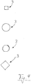
- unterschiedliche Formen von Zielkörpern in Ansicht von vorne.
- In
Figur 1 ist schematisch ein Verfahren zum Kalibrieren einer Wärmebilderfassung einer Schußwaffe, insbesondere eines Gewehrs, angedeutet, wobei das Gewehr - selbst nicht dargestellt - hier von einem Hochstand 2 was natürlich nicht zwingend ist, auf eine Zielsimulation 1 abgeschossen wird. Das Verfahren kann bei Helligkeit oder insbesondere auch bei Nebel, Dunkelheit oder anderer Sichteinschränkung durchgeführt werden. - Insbesondere wird eine derartige Schußwaffe zunächst bei Sicht eingeschossen und ggf. auch hinsichtlich einer Wärmebilderfassung optimiert. Wenn dann in der folgenden Nacht gejagt werden soll, wird die Wärmebilderfassung dann im Dunkeln mit dem genannten Verfahren kalibriert. Die Schußwaffe ist hierfür mit einer Wärmebilderfassung versehen, die beispielsweise mit Hilfe eines Nachtsichtzielgeräts oder eines Wärmebildzielgeräts arbeitet. Dabei kann eine Feinjustierung in jeder Richtung möglich sein, etwa auch eines Monitors, der ein Wärmebild optisch anzeigen kann.
- Unter einem Einschießen und der zugehörigen Kalibrierung wird hier jedwedes Schießen auf eine Zielsimulation 1 verstanden. Diese kann auch beispielsweise beweglich sein - hier nicht dargestellt -, zum Beispiel über einen motorischen Antrieb. Das Kalibrieren muß nicht am Anfang eines Jagens stehen, sondern kann auch zwischendrin immer wieder durchgeführt werden.
- Für das Verfahren wird in einem Abstand zur Schußwaffe eine zu treffende (feste oder bewegliche) Zielsimulation 1 angeordnet. Der Abstand kann dem entsprechen, der üblichen Jagd- und Schußbedingungen entspricht, also in Horizontalrichtung typisch 50 Meter bis deutlich über 100 Meter betragen.
- Diese Zielsimulation 1 ist in Funktion zumindest mit einem wärmeabgebenden Zielkörper 3 versehen - oder besteht aus diesem -, der beispielsweise auf eine Zielkarte 4 in deren Zentrum aufgeklebt ist. Die Verwendung einer Zielkarte 4 ist natürlich nicht zwingend. Der Zielkörper 3 kann auch für sich eine Zielsimulation 1 darstellen.
- Der Zielkörper 3 oder die diesen haltende Zielkarte 4 kann ihrerseits an einem Baum 5, einem Zaun oder einer anderen Halterung festgelegt sein. Die Art der Festlegung ist variabel: beispielsweise kommt einfach ein Kleben oder Nageln in Frage.
- Durch den wärmeabgebenden Zielkörper 3 ist dieser auch aus großer Entfernung über eine Infraroterfassung, beispielsweise über ein Nachtsichtzielgerät oder ein Wärmebildzielgerät, erkennbar, auch wenn kein oder zu wenig Licht im sichtbaren Bereich vorhanden ist. Dabei kann ein gesondertes Nachtsichtgerät und/oder insbesondere ein Zielfernrohr mit Infraroterfassung an der Schußwaffe verwendet werden, um das Wärmesignal (Infrarotstrahlung) über den Abstand zu erfassen. Die Temperatur des Zielkörpers 3 liegt in Funktion vorzugsweise bei über 35°C. Bei der angesprochenen chemischen Reaktion treten über 6 bis 24 Stunden Temperaturen von ca. 50°C auf.
- Es werden nach Plazierung der Zielsimulation 1 mehrere Schüsse entlang der gestrichelt eingezeichneten Schußlinie 6 auf den Wärmekörper 3 abgegeben; anschließend geht der Schütze oder eine andere Person zur Zielkarte und betrachtet, an welcher Stelle (des Zielkörpers 3 oder der umliegenden Zielkarte 4) die Schüsse eingeschlagen haben. Anhand der Abweichung läßt sich die Kalibrierung der Wärmebilderfassung, zum Beispiel die Feinausrichtung eines Monitors für das Wärmebild, korrigieren. Dann bildet das Wärmebild exakt die Realität ab, so daß dann die Schußwaffe zielgenau eingesetzt werden kann. Eventuell muß das Einschießen mit der genannten Kalibrierung mehrere Male durchgeführt werden. Die Zielkörper 3 können selbst zerschossen werden, dies ist unkritisch.
- Der wärmeabgebende Zielkörper 3 kann pflasterartig ausgebildet sein, wobei die Rückseite, die etwa auf die Zielkarte 4 geklebt wird, für ein einfaches Handling insbesondere selbstklebend ausgeführt sein kann, jedoch nicht muß. Eine Schutzfolie der Klebefläche 9 kann vor Ort abgezogen werden.
- Der wärmeabgebende Zielkörper 3 kann beispielsweise mit einer Substanz nach Art eines Handwärmers versehen oder befüllt sein. Für eine Einmalverwendung kann hierbei der wärmeabgebende Zielkörper 3 Eisenpulver oder ein anderes Material enthalten, das mit Luftsauerstoff in einer exothermen Reaktion zu Eisenoxid bzw. einem anderen Oxid reagiert. Die Wärmeabgabe setzt dann automatisch durch Zufuhr von Luftsauerstoff, also durch Öffnen der Verpackung, ein. In dem Fall ist es sinnvoll, die Zielkörper 3 bis zu ihrem Einsatz vereinzelt in einer luftdichten Verpackung zu halten. Insbesondere kann für jeden Zielkörper 3 ein einzelnes luftdichtes Abteil vorgesehen sein; diese können als zusammenhängender Abreißstreifen, etwa über Perforationen, ausgebildet sein.
- Auch andere chemische und/oder physikalische Mechanismen für die Wärmeabgabe können möglich sein. Dabei ist je nach Mechanismus wie hier eine Einmalverwendung möglich, oder es kann alternativ eine Mehrfachverwendung der Zielkörper 3 möglich sein.
- Um ein exaktes Anpeilen beim Schießen zu ermöglichen, hat günstig der wärmeabgebende Zielkörper 3 eine regelmäßige geometrische Umrißgestalt, wie etwa eine Kreisform, eine quadratische, sechs- oder achteckige Form. In
Figur 4 sind ein paar solcher Formen angedeutet. Die Kantenlänge 7 bzw. der Durchmesser 8 liegt dabei insbesondere unterhalb von 40 Millimetern, um eine zu breite und schwammige Wärmeabstrahlung zu vermeiden. Besonders günstig sind Kantenlängen von ca. 30 Millimetern. - Um den Zielkörper 3 herum kann auch noch ein schmaler, nicht befüllter Saum eines Pads oder ähnliches vorgesehen sein. Dieser kann etwa eine Dicke von 3 bis 8 Millimetern haben.
- Je nach Ausbildung des Zielkörpers 3 kann es möglich sein, diesen zurechtzuschneiden. Sofern er jedoch Eisenpulver oder ähnliches enthält, kann dieses jedoch, sofern nicht gebunden, beim Zuschneiden herausrieseln.
- Deswegen ist alternativ vorgesehen, daß ein wärmeabgebender Zielkörper 3 in verschiedenen Maßen und Außenumrißgestalten angeboten wird und direkt passend verwendet werden kann.
- Hierfür können zum Beispiel Zielkörper 3 entweder von Anfang an vollständig vereinzelt sein oder an einer Perforation voneinander abgetrennt und direkt vor Benutzung in das Zentrum einer Zielkarte 4 geklebt werden.
- Derartige Zielkörper 3 können eine Dicke von zum Beispiel wenigen Millimetern bis etwa 10 Millimeter aufweisen, wie etwa in
Figur 3 sichtbar ist. Der Zielkörper 3 muß keine exakt rechtwinklige Form aufweisen, sondern kann eine leichte Kissenform und Verformbarkeit zeigen. - Um auch eine optische Erfassung des Zielkörpers 3 zu ermöglichen, kann der wärmeabgebende Zielkörper zusätzlich mit einem phosphoreszierenden und/oder fluoreszierenden Stoff versehen sein und auch Licht im sichtbaren Bereich abgeben. Dies erleichtert die Kontrolle der korrekten Schußbahn 6. Auch ein längeres Nachleuchten ist dabei möglich.
-
- 1
- Zielsimulation,
- 2
- Hochstand,
- 3
- wärmeabgebender Zielkörper,
- 4
- Zielkarte,
- 5
- Baum,
- 6
- Schußlinie,
- 7
- Kantenlänge,
- 8
- Durchmesser,
- 9
- Klebefläche
Claims (15)
- Verfahren zum Einschießen einer Schußwaffe, insbesondere eines Gewehrs, mit einer Zieleinrichtung, die ein Erfassen eines Wärmebilds ermöglicht, wobei in einem Abstand zur Schußwaffe eine zu treffende Zielsimulation (1) angeordnet wird,
dadurch gekennzeichnet,
daß die Zielsimulation (1) mit einem wärmeabgebenden Zielkörper (3) versehen wird, der maximale Kantenlängen (7) oder einem maximalen Durchmesser (8) von weniger als 40 Millimetern aufweist. - Verfahren nach Anspruch 1,
dadurch gekennzeichnet,
daß der wärmeabgebende Zielkörper (3) pflasterartig ausgebildet ist. - Verfahren nach einem der Ansprüche 1 oder 2,
dadurch gekennzeichnet,
daß der wärmeabgebende Zielkörper (3) mit einer Substanz nach Art eines Handwärmers versehen oder befüllt ist. - Verfahren nach einem der Ansprüche 1 bis 3,
dadurch gekennzeichnet,
daß der wärmeabgebende Zielkörper (3) Eisenpulver oder ein anderes Material enthält, das mit Luftsauerstoff in einer exothermen Reaktion zu Eisenoxid bzw. einem anderen Oxid reagiert. - Verfahren nach einem der Ansprüche 1 bis 4,
dadurch gekennzeichnet,
daß der wärmeabgebende Zielkörper (3) eine regelmäßige geometrische insbesondere rechteckige oder runde, Umrißgestalt hat. - Verfahren nach einem der Ansprüche 1 bis 4,
dadurch gekennzeichnet,
daß der wärmeabgebende Zielkörper maximale Kantenlängen (7) bzw. Durchmesser (8) von weniger als 30 Millimetern aufweist. - Verfahren nach einem der Ansprüche 1 bis 6,
dadurch gekennzeichnet,
daß der wärmeabgebende Zielkörper (3) vor Benutzung in das Zentrum einer Zielkarte (4) geklebt wird. - Zielsimulation (1) zum Einschießen einer Schußwaffe, insbesondere eines Gewehrs, mit einer Zieleinrichtung, die ein Erfassen eines Wärmebilds ermöglicht,
dadurch gekennzeichnet,
daß die Zielsimulation (1) zumindest einen in Funktion wärmeabgebenden Zielkörper (3) umfaßt, der maximale Kantenlängen (7) oder einem maximalen Durchmesser (8) von weniger als 40 Millimetern aufweist. - Zielsimulation (1) nach Anspruch 8,
dadurch gekennzeichnet,
daß der wärmeabgebende Zielkörper (3) pflasterartig ausgebildet und am Zentrum einer Zielkarte (4) befestigt oder befestigbar ist. - Zielsimulation (1) nach einem der Ansprüche 8 oder 9,
dadurch gekennzeichnet,
daß der wärmeabgebende Zielkörper (3) mit einer Substanz nach Art eines Handwärmers versehen oder, befüllt ist. - Zielsimulation (1) nach einem der Ansprüche 8 bis 10,
dadurch gekennzeichnet,
daß der wärmeabgebende Zielkörper (3) maximale Kantenlängen (7) bzw. Durchmesser (8) von weniger als 30 Millimetern, aufweist. - Zielsimulation (1) nach einem der Ansprüche 8 bis 11,
dadurch gekennzeichnet,
daß der wärmeabgebende Zielkörper (3) bis zum Einsatz in einer luftdichten Verpackung gehalten ist. - Zielsimulation (1) nach Anspruch 12,
dadurch gekennzeichnet,
daß die luftdichte Verpackung eine Mehrzahl von einzeln abreißbaren Abteilungen umfaßt. - Zielsimulation (1) nach einem der Ansprüche 8 bis 13,
dadurch gekennzeichnet,
daß der wärmeabgebende Zielkörper (3) selbstklebend ist. - Zielsimulation (1) nach einem der Ansprüche 8 bis 14,
dadurch gekennzeichnet,
daß der wärmeabgebende Zielkörper (3) zusätzlich mit einem phosphoreszierenden und/oder fluoreszierenden Stoff versehen ist und Licht im sichtbaren Bereich abgibt.
Applications Claiming Priority (1)
| Application Number | Priority Date | Filing Date | Title |
|---|---|---|---|
| DE102019000225.3A DE102019000225A1 (de) | 2019-01-16 | 2019-01-16 | Zielerfassung |
Publications (3)
| Publication Number | Publication Date |
|---|---|
| EP3683536A1 true EP3683536A1 (de) | 2020-07-22 |
| EP3683536B1 EP3683536B1 (de) | 2023-06-07 |
| EP3683536C0 EP3683536C0 (de) | 2023-06-07 |
Family
ID=69104195
Family Applications (1)
| Application Number | Title | Priority Date | Filing Date |
|---|---|---|---|
| EP19000597.5A Active EP3683536B1 (de) | 2019-01-16 | 2019-12-28 | Zielerfassung |
Country Status (2)
| Country | Link |
|---|---|
| EP (1) | EP3683536B1 (de) |
| DE (1) | DE102019000225A1 (de) |
Families Citing this family (2)
| Publication number | Priority date | Publication date | Assignee | Title |
|---|---|---|---|---|
| DE102019000225A1 (de) | 2019-01-16 | 2020-07-16 | André Roekens | Zielerfassung |
| US20240377166A1 (en) * | 2023-05-11 | 2024-11-14 | Christopher M. Thompson | Thermal shooting targets and systems |
Citations (8)
| Publication number | Priority date | Publication date | Assignee | Title |
|---|---|---|---|---|
| GB2184215A (en) | 1985-10-15 | 1987-06-17 | Fulmer Res Inst Ltd | Thermal image targets |
| US6337475B1 (en) * | 2000-02-24 | 2002-01-08 | The United States Of America As Represented By The Secretary Of The Army | Thermal silhouette target and zeroing technique |
| US6767015B1 (en) * | 2003-06-05 | 2004-07-27 | The United States Of America As Represented By The Secretary Of The Navy | Thermal target |
| US20090008541A1 (en) | 2006-03-31 | 2009-01-08 | Boyer Thomas R | Thermal infrared signage method with application to infrared weapon sight calibration |
| US20110175292A1 (en) * | 2008-02-07 | 2011-07-21 | Carni Anthony R | Thermal Signature Target |
| US20120218633A1 (en) | 2011-02-24 | 2012-08-30 | Cincotti K Dominic | Targets, target training systems, and methods |
| US20170350678A1 (en) * | 2016-06-06 | 2017-12-07 | Thomas R. Boyer | Universal weapon zeroing target |
| DE102019000225A1 (de) | 2019-01-16 | 2020-07-16 | André Roekens | Zielerfassung |
Family Cites Families (1)
| Publication number | Priority date | Publication date | Assignee | Title |
|---|---|---|---|---|
| DE10150069A1 (de) * | 2001-10-10 | 2003-04-30 | Bundesrep Deutschland | Wärmebildfähige Zielscheibe |
-
2019
- 2019-01-16 DE DE102019000225.3A patent/DE102019000225A1/de not_active Withdrawn
- 2019-12-28 EP EP19000597.5A patent/EP3683536B1/de active Active
Patent Citations (8)
| Publication number | Priority date | Publication date | Assignee | Title |
|---|---|---|---|---|
| GB2184215A (en) | 1985-10-15 | 1987-06-17 | Fulmer Res Inst Ltd | Thermal image targets |
| US6337475B1 (en) * | 2000-02-24 | 2002-01-08 | The United States Of America As Represented By The Secretary Of The Army | Thermal silhouette target and zeroing technique |
| US6767015B1 (en) * | 2003-06-05 | 2004-07-27 | The United States Of America As Represented By The Secretary Of The Navy | Thermal target |
| US20090008541A1 (en) | 2006-03-31 | 2009-01-08 | Boyer Thomas R | Thermal infrared signage method with application to infrared weapon sight calibration |
| US20110175292A1 (en) * | 2008-02-07 | 2011-07-21 | Carni Anthony R | Thermal Signature Target |
| US20120218633A1 (en) | 2011-02-24 | 2012-08-30 | Cincotti K Dominic | Targets, target training systems, and methods |
| US20170350678A1 (en) * | 2016-06-06 | 2017-12-07 | Thomas R. Boyer | Universal weapon zeroing target |
| DE102019000225A1 (de) | 2019-01-16 | 2020-07-16 | André Roekens | Zielerfassung |
Non-Patent Citations (5)
| Title |
|---|
| "Fünf Screenshots aus dem Video „Homemade ATN Thor Thermal Scope Zero Target", YOUTUBE, Retrieved from the Internet <URL:https://www.youtube.com/watch?v=BDe9LbbmqQE. > |
| "Homemade ATN Thor Thermal Scope Zero Target", YOUTUBE, 7 January 2018 (2018-01-07) |
| "Homemade ATN Thor Thermal Scope Zero Target", YOUTUBE, Retrieved from the Internet <URL:https://www.youtube.com/watch?v=BDe9LbbmqQE> |
| GEARTESTER.DE: "Einschießen mit Wärmebildvorsatzgerät. Das ist zu beachten!", YOUTUBE, 24 December 2018 (2018-12-24), XP093051343, Retrieved from the Internet <URL:https://www.youtube.com/watch?v=ZJ6I0XQak3k> [retrieved on 20230602] |
| IR.TOOLS™: "Thermal Zeroing Target", YOUTUBE, 26 November 2018 (2018-11-26), XP093051348, Retrieved from the Internet <URL:https://www.youtube.com/watch?v=V-OTVvT0AIQ> [retrieved on 20230602] |
Also Published As
| Publication number | Publication date |
|---|---|
| EP3683536B1 (de) | 2023-06-07 |
| DE102019000225A1 (de) | 2020-07-16 |
| EP3683536C0 (de) | 2023-06-07 |
Similar Documents
| Publication | Publication Date | Title |
|---|---|---|
| DE4444637C2 (de) | Laser-Waffensystem | |
| DE102020128610A1 (de) | Mikropunktvisier mit einem dualemitter | |
| DE2750776C3 (de) | Azimutal richtbare Abschußvorrichtung | |
| EP3683536B1 (de) | Zielerfassung | |
| DE3210834A1 (de) | Zielhilfe fuer schrotflinten | |
| EP3068208B1 (de) | System zum erfassen von parametern der umwelt und umgebung | |
| DE102016108138A1 (de) | Kollisionszielattrappe | |
| DE3705383C2 (de) | ||
| DE112020002404T5 (de) | Proportional reagierende konduktive Energiewaffe sowie Verfahren | |
| DE102005007910A1 (de) | Feuerwaffe für langsam fliegende Geschosse | |
| DE202019000992U1 (de) | Zielerfassung bei insbesondere Dunkelheit | |
| DE3716883A1 (de) | Elektronisches mess- und pruefsystem zur analyse von waffen und deren munition | |
| EP3118561B1 (de) | Energiewirksystem und waffensystem | |
| DE102017000486B4 (de) | System und Verfahren zur ballistischen Untersuchung von Geschossen | |
| DE2522927C2 (de) | System zur taeuschung, ablenkung und vernichtung von lenkwaffen | |
| DE102020004487A1 (de) | Wirkmittel zur Bekämpfung eines Ziels | |
| DE102010060914A1 (de) | Chirurgisches Markerelement, chirurgische Referenzierungseinheit und chirurgisches Navigationssystem | |
| DE10147837A1 (de) | Wurfsystem für einen Gefechtskopf mit einer Richtvorrichtung zur Neutralisierung von Minen | |
| DE112023000301T5 (de) | Vorrichtung zur Präzisionszielerfassung bei Waffen | |
| DE1489750B2 (de) | Strahlungsdetektor zum sichtbarmachen und betrachten von un sichtbaren strahlen | |
| DE19601506C2 (de) | Verfahren und Vorrichtung zur Erzeugung einer Sichtsperre mit Hilfe eines künstlichen Nebels | |
| DE102012002687A1 (de) | Granate mit einem Markierungsstoff | |
| DE3127844C2 (de) | Verfahen zum Abwerfen von Munition von einem Kampfflugzeug aus | |
| DE102005015906B3 (de) | Handgranate | |
| DE102024205572A1 (de) | Verfahren und Vorrichtung zur Auswertung eines Zielbildes |
Legal Events
| Date | Code | Title | Description |
|---|---|---|---|
| PUAI | Public reference made under article 153(3) epc to a published international application that has entered the european phase |
Free format text: ORIGINAL CODE: 0009012 |
|
| STAA | Information on the status of an ep patent application or granted ep patent |
Free format text: STATUS: THE APPLICATION HAS BEEN PUBLISHED |
|
| AK | Designated contracting states |
Kind code of ref document: A1 Designated state(s): AL AT BE BG CH CY CZ DE DK EE ES FI FR GB GR HR HU IE IS IT LI LT LU LV MC MK MT NL NO PL PT RO RS SE SI SK SM TR |
|
| AX | Request for extension of the european patent |
Extension state: BA ME |
|
| STAA | Information on the status of an ep patent application or granted ep patent |
Free format text: STATUS: REQUEST FOR EXAMINATION WAS MADE |
|
| 17P | Request for examination filed |
Effective date: 20210119 |
|
| RBV | Designated contracting states (corrected) |
Designated state(s): AL AT BE BG CH CY CZ DE DK EE ES FI FR GB GR HR HU IE IS IT LI LT LU LV MC MK MT NL NO PL PT RO RS SE SI SK SM TR |
|
| STAA | Information on the status of an ep patent application or granted ep patent |
Free format text: STATUS: EXAMINATION IS IN PROGRESS |
|
| 17Q | First examination report despatched |
Effective date: 20220809 |
|
| GRAP | Despatch of communication of intention to grant a patent |
Free format text: ORIGINAL CODE: EPIDOSNIGR1 |
|
| STAA | Information on the status of an ep patent application or granted ep patent |
Free format text: STATUS: GRANT OF PATENT IS INTENDED |
|
| INTG | Intention to grant announced |
Effective date: 20220920 |
|
| GRAS | Grant fee paid |
Free format text: ORIGINAL CODE: EPIDOSNIGR3 |
|
| GRAA | (expected) grant |
Free format text: ORIGINAL CODE: 0009210 |
|
| STAA | Information on the status of an ep patent application or granted ep patent |
Free format text: STATUS: THE PATENT HAS BEEN GRANTED |
|
| TPAC | Observations filed by third parties |
Free format text: ORIGINAL CODE: EPIDOSNTIPA |
|
| AK | Designated contracting states |
Kind code of ref document: B1 Designated state(s): AL AT BE BG CH CY CZ DE DK EE ES FI FR GB GR HR HU IE IS IT LI LT LU LV MC MK MT NL NO PL PT RO RS SE SI SK SM TR |
|
| REG | Reference to a national code |
Ref country code: GB Ref legal event code: FG4D Free format text: NOT ENGLISH |
|
| REG | Reference to a national code |
Ref country code: CH Ref legal event code: EP Ref country code: AT Ref legal event code: REF Ref document number: 1576311 Country of ref document: AT Kind code of ref document: T Effective date: 20230615 |
|
| REG | Reference to a national code |
Ref country code: DE Ref legal event code: R096 Ref document number: 502019007837 Country of ref document: DE |
|
| U01 | Request for unitary effect filed |
Effective date: 20230705 |
|
| U07 | Unitary effect registered |
Designated state(s): AT BE BG DE DK EE FI FR IT LT LU LV MT NL PT SE SI Effective date: 20230714 |
|
| REG | Reference to a national code |
Ref country code: LT Ref legal event code: MG9D |
|
| PG25 | Lapsed in a contracting state [announced via postgrant information from national office to epo] |
Ref country code: NO Free format text: LAPSE BECAUSE OF FAILURE TO SUBMIT A TRANSLATION OF THE DESCRIPTION OR TO PAY THE FEE WITHIN THE PRESCRIBED TIME-LIMIT Effective date: 20230907 Ref country code: ES Free format text: LAPSE BECAUSE OF FAILURE TO SUBMIT A TRANSLATION OF THE DESCRIPTION OR TO PAY THE FEE WITHIN THE PRESCRIBED TIME-LIMIT Effective date: 20230607 |
|
| PG25 | Lapsed in a contracting state [announced via postgrant information from national office to epo] |
Ref country code: RS Free format text: LAPSE BECAUSE OF FAILURE TO SUBMIT A TRANSLATION OF THE DESCRIPTION OR TO PAY THE FEE WITHIN THE PRESCRIBED TIME-LIMIT Effective date: 20230607 Ref country code: HR Free format text: LAPSE BECAUSE OF FAILURE TO SUBMIT A TRANSLATION OF THE DESCRIPTION OR TO PAY THE FEE WITHIN THE PRESCRIBED TIME-LIMIT Effective date: 20230607 Ref country code: GR Free format text: LAPSE BECAUSE OF FAILURE TO SUBMIT A TRANSLATION OF THE DESCRIPTION OR TO PAY THE FEE WITHIN THE PRESCRIBED TIME-LIMIT Effective date: 20230908 |
|
| PG25 | Lapsed in a contracting state [announced via postgrant information from national office to epo] |
Ref country code: SK Free format text: LAPSE BECAUSE OF FAILURE TO SUBMIT A TRANSLATION OF THE DESCRIPTION OR TO PAY THE FEE WITHIN THE PRESCRIBED TIME-LIMIT Effective date: 20230607 |
|
| PG25 | Lapsed in a contracting state [announced via postgrant information from national office to epo] |
Ref country code: IS Free format text: LAPSE BECAUSE OF FAILURE TO SUBMIT A TRANSLATION OF THE DESCRIPTION OR TO PAY THE FEE WITHIN THE PRESCRIBED TIME-LIMIT Effective date: 20231007 |
|
| U20 | Renewal fee for the european patent with unitary effect paid |
Year of fee payment: 5 Effective date: 20231221 |
|
| PG25 | Lapsed in a contracting state [announced via postgrant information from national office to epo] |
Ref country code: SM Free format text: LAPSE BECAUSE OF FAILURE TO SUBMIT A TRANSLATION OF THE DESCRIPTION OR TO PAY THE FEE WITHIN THE PRESCRIBED TIME-LIMIT Effective date: 20230607 Ref country code: SK Free format text: LAPSE BECAUSE OF FAILURE TO SUBMIT A TRANSLATION OF THE DESCRIPTION OR TO PAY THE FEE WITHIN THE PRESCRIBED TIME-LIMIT Effective date: 20230607 Ref country code: RO Free format text: LAPSE BECAUSE OF FAILURE TO SUBMIT A TRANSLATION OF THE DESCRIPTION OR TO PAY THE FEE WITHIN THE PRESCRIBED TIME-LIMIT Effective date: 20230607 Ref country code: IS Free format text: LAPSE BECAUSE OF FAILURE TO SUBMIT A TRANSLATION OF THE DESCRIPTION OR TO PAY THE FEE WITHIN THE PRESCRIBED TIME-LIMIT Effective date: 20231007 Ref country code: CZ Free format text: LAPSE BECAUSE OF FAILURE TO SUBMIT A TRANSLATION OF THE DESCRIPTION OR TO PAY THE FEE WITHIN THE PRESCRIBED TIME-LIMIT Effective date: 20230607 |
|
| PG25 | Lapsed in a contracting state [announced via postgrant information from national office to epo] |
Ref country code: PL Free format text: LAPSE BECAUSE OF FAILURE TO SUBMIT A TRANSLATION OF THE DESCRIPTION OR TO PAY THE FEE WITHIN THE PRESCRIBED TIME-LIMIT Effective date: 20230607 |
|
| REG | Reference to a national code |
Ref country code: DE Ref legal event code: R097 Ref document number: 502019007837 Country of ref document: DE |
|
| PLBE | No opposition filed within time limit |
Free format text: ORIGINAL CODE: 0009261 |
|
| STAA | Information on the status of an ep patent application or granted ep patent |
Free format text: STATUS: NO OPPOSITION FILED WITHIN TIME LIMIT |
|
| 26N | No opposition filed |
Effective date: 20240308 |
|
| REG | Reference to a national code |
Ref country code: CH Ref legal event code: PL |
|
| PG25 | Lapsed in a contracting state [announced via postgrant information from national office to epo] |
Ref country code: MC Free format text: LAPSE BECAUSE OF FAILURE TO SUBMIT A TRANSLATION OF THE DESCRIPTION OR TO PAY THE FEE WITHIN THE PRESCRIBED TIME-LIMIT Effective date: 20230607 |
|
| GBPC | Gb: european patent ceased through non-payment of renewal fee |
Effective date: 20231228 |
|
| PG25 | Lapsed in a contracting state [announced via postgrant information from national office to epo] |
Ref country code: MC Free format text: LAPSE BECAUSE OF FAILURE TO SUBMIT A TRANSLATION OF THE DESCRIPTION OR TO PAY THE FEE WITHIN THE PRESCRIBED TIME-LIMIT Effective date: 20230607 |
|
| REG | Reference to a national code |
Ref country code: IE Ref legal event code: MM4A |
|
| PG25 | Lapsed in a contracting state [announced via postgrant information from national office to epo] |
Ref country code: IE Free format text: LAPSE BECAUSE OF NON-PAYMENT OF DUE FEES Effective date: 20231228 |
|
| PG25 | Lapsed in a contracting state [announced via postgrant information from national office to epo] |
Ref country code: GB Free format text: LAPSE BECAUSE OF NON-PAYMENT OF DUE FEES Effective date: 20231228 |
|
| PG25 | Lapsed in a contracting state [announced via postgrant information from national office to epo] |
Ref country code: CH Free format text: LAPSE BECAUSE OF NON-PAYMENT OF DUE FEES Effective date: 20231231 |
|
| PG25 | Lapsed in a contracting state [announced via postgrant information from national office to epo] |
Ref country code: IE Free format text: LAPSE BECAUSE OF NON-PAYMENT OF DUE FEES Effective date: 20231228 Ref country code: GB Free format text: LAPSE BECAUSE OF NON-PAYMENT OF DUE FEES Effective date: 20231228 Ref country code: CH Free format text: LAPSE BECAUSE OF NON-PAYMENT OF DUE FEES Effective date: 20231231 |
|
| U20 | Renewal fee for the european patent with unitary effect paid |
Year of fee payment: 6 Effective date: 20241212 |
|
| PG25 | Lapsed in a contracting state [announced via postgrant information from national office to epo] |
Ref country code: CY Free format text: LAPSE BECAUSE OF FAILURE TO SUBMIT A TRANSLATION OF THE DESCRIPTION OR TO PAY THE FEE WITHIN THE PRESCRIBED TIME-LIMIT; INVALID AB INITIO Effective date: 20191228 |
|
| PG25 | Lapsed in a contracting state [announced via postgrant information from national office to epo] |
Ref country code: HU Free format text: LAPSE BECAUSE OF FAILURE TO SUBMIT A TRANSLATION OF THE DESCRIPTION OR TO PAY THE FEE WITHIN THE PRESCRIBED TIME-LIMIT; INVALID AB INITIO Effective date: 20191228 |
|
| PG25 | Lapsed in a contracting state [announced via postgrant information from national office to epo] |
Ref country code: TR Free format text: LAPSE BECAUSE OF FAILURE TO SUBMIT A TRANSLATION OF THE DESCRIPTION OR TO PAY THE FEE WITHIN THE PRESCRIBED TIME-LIMIT Effective date: 20230607 |
|
| U20 | Renewal fee for the european patent with unitary effect paid |
Year of fee payment: 7 Effective date: 20251211 |