EP3683374A1 - Upright-crosspiece assembly - Google Patents
Upright-crosspiece assembly Download PDFInfo
- Publication number
- EP3683374A1 EP3683374A1 EP20150454.5A EP20150454A EP3683374A1 EP 3683374 A1 EP3683374 A1 EP 3683374A1 EP 20150454 A EP20150454 A EP 20150454A EP 3683374 A1 EP3683374 A1 EP 3683374A1
- Authority
- EP
- European Patent Office
- Prior art keywords
- upright
- shelf
- connection element
- crosspiece
- assembly
- Prior art date
- Legal status (The legal status is an assumption and is not a legal conclusion. Google has not performed a legal analysis and makes no representation as to the accuracy of the status listed.)
- Withdrawn
Links
Images

Classifications
-
- E—FIXED CONSTRUCTIONS
- E04—BUILDING
- E04B—GENERAL BUILDING CONSTRUCTIONS; WALLS, e.g. PARTITIONS; ROOFS; FLOORS; CEILINGS; INSULATION OR OTHER PROTECTION OF BUILDINGS
- E04B2/00—Walls, e.g. partitions, for buildings; Wall construction with regard to insulation; Connections specially adapted to walls
- E04B2/88—Curtain walls
- E04B2/96—Curtain walls comprising panels attached to the structure through mullions or transoms
- E04B2/965—Connections of mullions and transoms
Definitions
- the present patent application for industrial invention relates to an upright-crosspiece assembly, in particular for the building sector, for the realization of continuous facades and/or ventilated facades of buildings.
- Crosspieces with protruding shelves connected to uprights are generally used in building facades.
- Rain water or condensation water flows on the shelf of the crosspiece and penetrates an empty space between upright and crosspiece, creating humidity and infiltrations in the facade.
- Plugs are known to prevent water from being drained from the shelf to the upright. However, in such a case, the water is drained frontally from the crosspiece.
- FR2694953 discloses an assembly comprising an upright, a crosspiece with a shelf that projects from the crosspiece, and a connection element to connect the crosspiece to the upright.
- the connection element has threaded holes and is made of a rigid material.
- connection element has a gap wherein a lateral edge of the shelf of the crosspiece is inserted. Therefore, the connection element forms a step on the shelf of the crosspiece. In view of the above, the water that flows on the shelf of the crosspiece is stopped against the step formed by the connection element and is drained from the crosspiece without reaching the upright.
- WO2004/042159 discloses a system that comprises a mullion, a transom with a shelf that protrudes from the transom, a tight plug disposed in a lateral edge of the transom, and an insert fastened to the mullion by means of screws and fitted into the plug.
- the plug is made of a rigid material in order to be fitted into the insert.
- the plug is designed to block the water flow on the shelf in order to prevent the water from reaching the mullion. In view of the above, the water is drained frontally from the shelf of the transom.
- the purpose of the present invention is to disclose an upright-crosspiece assembly capable of draining the water from the crosspiece towards the upright, in such a way that the water is drained on the upright, preventing the water from penetrating in an empty space between crosspiece and upright and dripping from the crosspiece.
- Another purpose is to disclose an upright-crosspiece assembly that is reliable, versatile and simple to make and install.
- the assembly (100) comprises a crosspiece (1), an upright (2) and a connection element (3) disposed between the crosspiece (1) and the upright (2).
- the crosspiece (1) has a rectangular shape and comprises a back side (11) suitable for facing a wall of a building, a front side (12) suitable for facing the exterior of the building, an upper side (13) and a lower side (14).
- the crosspiece (1) has two rectilinear lateral edges (15) at right angle with the front side and the back side.
- the crosspiece (1) comprises a shelf (16) that projects from the front side (12) of the crosspiece.
- the shelf (16) has two lateral edges (161) that are aligned with the lateral edges (15) of the crosspiece (1).
- the shelf (16) of the upright (1) is suitable for supporting a cover panel (P) for covering a facade of a building.
- the cover panel (P) can be internally empty to ensure a good thermal insulation.
- the panel (P) has a lower edge (P1) and a lateral edge (P2).
- the lower edge (P1) of the panel is disposed in contact with the shelf (16).
- the upright (2) has a back side (21) suitable for facing a wall of the building, a front side (22) suitable for facing the exterior of the building, and two lateral sides (23).
- the crosspiece (1) is disposed between the lateral sides (3) of two uprights.
- the assembly (100) may comprise closing elements (not shown in the drawings) to close empty spaces between the panel (P), the crosspiece (1) and the upright (2).
- connection element (3) is disposed between the lateral edge (161) of the shelf (16) and the front side (22) of the upright (2).
- connection element (3) is a seal made of a soft elastomeric material that is tightly engaged in the crosspiece and in the upright; preventing water from infiltrating between the crosspiece and the upright.
- the connection element is made in one piece.
- connection element (3) is suitably configured to act as conveyor element in such a way that the water that is deposited on the shelf (16) is drained laterally towards the upright (2), without encountering any obstacle and reaching the front side (22) of the upright in order to be drained along the front side of the upright. In this way, the water is prevented from draining frontally from the shelf and from penetrating in an empty space between the lateral edge (166) of the shelf and the lateral side (23) of the upright.
- the crosspiece (1) comprises fixing seats (S2, S2') for fixing the connection element (3).
- the upright (2) comprises a fixing seat (S3) for fixing the connection element (3).
- connection element (3) comprises:
- the fixing seats (S2, S2') of the crosspiece comprise:
- the grooves (S2, S2') have a narrowed opening, in such a way to define undercut parts.
- the first fixing means (A2, A2') of the connection element (3) comprise a first tooth (A2) and a second tooth (A2').
- the first tooth and the second tooth (A2, A2') are respectively inserted in the first and in the second groove (S2, S2') of the crosspiece.
- each tooth (A2, A2') of the first fixing means comprises a hook (33) that protrudes laterally outwards in order to be inserted through the narrowed opening of the grooves (S2, S2') of the crosspiece and be fixed in the undercut parts of the grooves of the crosspiece, in such a way to firmly fix the connection element to the crosspiece.
- the shelf (16) comprises a guide seat (S1) composed of a notch provided on the shelf (16) of the crosspiece (1).
- connection element (3) comprises guide means (A1) that are engaged in the guide seat (S1) of the shelf.
- the notch (S1) of the guide seat of the shelf has a U-shaped section with concavity directed towards the exterior of the building.
- the guide means (A1) of the connection element comprise a central wing (34) disposed between the two teeth (A1, A2).
- the central wing (34) is inserted in the notch of the guide means (S1) of the shelf and acts as guide for the correct alignment of the connection element. It must be noted that, when the central wing (34) of the connection element is inserted in the guide seat (S1) of the shelf, the tooth (A2) in upper position is separated from the upper surface of the shelf, in order to not interfere with the water flow from the shelf (16) towards the connection element (3)
- connection element (3) comprises a central portion (31) connected to the central wing (34).
- an upper surface of the central portion (31) of the connection element is disposed at the same height as an upper surface of the shelf (16), in correspondence of the lateral edge (161) of the shelf (16), in such a way that the water on the shelf can flow freely from the shelf to the central portion (31) of the connection element, without encountering any obstacle.
- a step (35) is provided between the central wing (34) and the central portion (31) of the connection element, and is stopped against the lateral edge (161) of the shelf.
- the thickness of the step (35) is such that an upper surface of the central portion (31) of the connection element is disposed at the same level as an upper surface of the shelf (16), in correspondence of the lateral edge (161) of the shelf (16).
- the central portion (31) of the connection element (3) has an upper surface with a first section (36) that is parallel to the central wing (34) and a second section (37) that is inclined relative to the first section (36).
- first section (36) of the central portion of the connection element is coplanar to the upper surface of the shelf, and the second section (37) of the central portion of the connection element is inclined downwards to favor the water drainage towards the front side (22) of the upright (2).
- the central wing (34) of the connection element that is disposed in the notch of the guide means (S1) of the shelf permits the stabilization of the connection element (3) in position, in such a way that the first section (36) of the central portion of the connection element is perfectly coplanar to the upper surface of the shelf (16).
- the fixing seat (S3) of the upright is a longitudinal notch on the front side (22) of the upright, near the lateral side (23) of the upright.
- the second fixing means (A3) of the connection element (3) comprise at least three retention teeth (A3) that are fastened inside the longitudinal notch of the fixing seat (S3) of the upright.
- the retention teeth (A3) are aligned in such a way to have a central retention tooth and two lateral retention teeth.
- each retention tooth (A3) comprises a hooked end (B).
- the hooked end of the central retention tooth is directed in the opposite direction relative to the hooked ends of the lateral retention teeth. More precisely, the hooked end of the central retention tooth is directed towards the upright (1), whereas the hooked ends of the lateral retention teeth are directed in the opposite direction.
Abstract
Assembly (100) comprising: an upright (2), a crosspiece (1) comprising a shelf (16) that protrudes frontally from the crosspiece (1) and a connection element (3) disposed between a lateral edge (161) of the shelf and a front side (22) of the upright (2); the connection element (3) is a seal made of soft elastomeric material that is tightly engaged in the crosspiece and in the upright; and the connection element (3) is suitably configured to act as water conveyor element, in such a way that the water that is deposited on the shelf (16) is laterally drained towards the upright (2), without encountering any obstacles and reaching the front side (22) of the upright in order to be drained along the front side of the upright.
Description
- The present patent application for industrial invention relates to an upright-crosspiece assembly, in particular for the building sector, for the realization of continuous facades and/or ventilated facades of buildings.
- Crosspieces with protruding shelves connected to uprights are generally used in building facades. Rain water or condensation water flows on the shelf of the crosspiece and penetrates an empty space between upright and crosspiece, creating humidity and infiltrations in the facade. Plugs are known to prevent water from being drained from the shelf to the upright. However, in such a case, the water is drained frontally from the crosspiece.
-
FR2694953 - The connection element has a gap wherein a lateral edge of the shelf of the crosspiece is inserted. Therefore, the connection element forms a step on the shelf of the crosspiece. In view of the above, the water that flows on the shelf of the crosspiece is stopped against the step formed by the connection element and is drained from the crosspiece without reaching the upright.
- If the coupling between the shelf and the gap of the connection element is loose, water penetrates into the connection element, and humidity is created.
-
WO2004/042159 discloses a system that comprises a mullion, a transom with a shelf that protrudes from the transom, a tight plug disposed in a lateral edge of the transom, and an insert fastened to the mullion by means of screws and fitted into the plug. The plug is made of a rigid material in order to be fitted into the insert. Moreover, the plug is designed to block the water flow on the shelf in order to prevent the water from reaching the mullion. In view of the above, the water is drained frontally from the shelf of the transom. - The purpose of the present invention is to disclose an upright-crosspiece assembly capable of draining the water from the crosspiece towards the upright, in such a way that the water is drained on the upright, preventing the water from penetrating in an empty space between crosspiece and upright and dripping from the crosspiece.
- Another purpose is to disclose an upright-crosspiece assembly that is reliable, versatile and simple to make and install.
- These purposes are achieved according to the invention with the characteristics of the appended
independent claim 1. - Advantageous embodiments appear from the dependent claims.
- The assembly of the invention is defined by
claim 1. - For the sake of clarity, the description of the assembly according to the invention continues with reference to the attached drawings, which only have an illustrative, not limiting value, wherein:
-
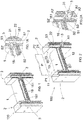
Fig.1 is an axonometric view of an assembly according to the invention; -
Fig.1 A is an enlarged view of a detail ofFig.1 ; -
Fig. 2 is an axonometric view of the assembly ofFig.1 , with an exploded view of two connection elements and one cover panel; -
Fig. 2A is an enlarged view of a detail ofFig.2 ; -
Figs. 3, 3A, 3B, 3C, 3D and 3E are a view of a connection element of the assembly ofFig.1 , seen from different angles; -
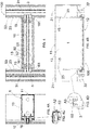
Figs. 4, 4A, 4B are respectively a front view, a side view and a plan view of the assembly ofFig.1 ; -
Fig. 4C is an enlarged view ofFig.4A ; -
Fig. 4D is an enlarged view ofFig.4B . - With reference to
Figs. 1, 2 and4B , an assembly according to the invention is disclosed, which is generally indicated with reference numeral (100). - The assembly (100) comprises a crosspiece (1), an upright (2) and a connection element (3) disposed between the crosspiece (1) and the upright (2).
- The crosspiece (1) has a rectangular shape and comprises a back side (11) suitable for facing a wall of a building, a front side (12) suitable for facing the exterior of the building, an upper side (13) and a lower side (14). The crosspiece (1) has two rectilinear lateral edges (15) at right angle with the front side and the back side.
- The crosspiece (1) comprises a shelf (16) that projects from the front side (12) of the crosspiece. The shelf (16) has two lateral edges (161) that are aligned with the lateral edges (15) of the crosspiece (1).
- The shelf (16) of the upright (1) is suitable for supporting a cover panel (P) for covering a facade of a building. The cover panel (P) can be internally empty to ensure a good thermal insulation. The panel (P) has a lower edge (P1) and a lateral edge (P2). The lower edge (P1) of the panel is disposed in contact with the shelf (16).
- The upright (2) has a back side (21) suitable for facing a wall of the building, a front side (22) suitable for facing the exterior of the building, and two lateral sides (23). In view of the above, the crosspiece (1) is disposed between the lateral sides (3) of two uprights.
- The assembly (100) may comprise closing elements (not shown in the drawings) to close empty spaces between the panel (P), the crosspiece (1) and the upright (2).
- The connection element (3) is disposed between the lateral edge (161) of the shelf (16) and the front side (22) of the upright (2).
- The connection element (3) is a seal made of a soft elastomeric material that is tightly engaged in the crosspiece and in the upright; preventing water from infiltrating between the crosspiece and the upright. The connection element is made in one piece.
- The connection element (3) is suitably configured to act as conveyor element in such a way that the water that is deposited on the shelf (16) is drained laterally towards the upright (2), without encountering any obstacle and reaching the front side (22) of the upright in order to be drained along the front side of the upright. In this way, the water is prevented from draining frontally from the shelf and from penetrating in an empty space between the lateral edge (166) of the shelf and the lateral side (23) of the upright.
- With reference to
Figs. 1A, 2A and4 , the crosspiece (1) comprises fixing seats (S2, S2') for fixing the connection element (3). The upright (2) comprises a fixing seat (S3) for fixing the connection element (3). - With reference to
Figs. 3 to 3E , the connection element (3) comprises: - first fixing means (A2, A2') that are engaged in the fixing seats (S2, S2') of the crosspiece (1), and
- second fixing means (A3) that are engaged in the fixing seat (S3) of the upright (2).
- The fixing seats (S2, S2') of the crosspiece comprise:
- a first groove (S2) disposed in the front side of the upright under the shelf, and
- a second groove (S2') disposed in the front side of the crosspiece above the shelf.
- The grooves (S2, S2') have a narrowed opening, in such a way to define undercut parts.
- With reference to
Figs. 3A, 3B and 3E , the first fixing means (A2, A2') of the connection element (3) comprise a first tooth (A2) and a second tooth (A2'). The first tooth and the second tooth (A2, A2') are respectively inserted in the first and in the second groove (S2, S2') of the crosspiece. More precisely, each tooth (A2, A2') of the first fixing means comprises a hook (33) that protrudes laterally outwards in order to be inserted through the narrowed opening of the grooves (S2, S2') of the crosspiece and be fixed in the undercut parts of the grooves of the crosspiece, in such a way to firmly fix the connection element to the crosspiece. - The shelf (16) comprises a guide seat (S1) composed of a notch provided on the shelf (16) of the crosspiece (1).
- The connection element (3) comprises guide means (A1) that are engaged in the guide seat (S1) of the shelf.
- The notch (S1) of the guide seat of the shelf has a U-shaped section with concavity directed towards the exterior of the building.
- The guide means (A1) of the connection element comprise a central wing (34) disposed between the two teeth (A1, A2).
- The central wing (34) is inserted in the notch of the guide means (S1) of the shelf and acts as guide for the correct alignment of the connection element. It must be noted that, when the central wing (34) of the connection element is inserted in the guide seat (S1) of the shelf, the tooth (A2) in upper position is separated from the upper surface of the shelf, in order to not interfere with the water flow from the shelf (16) towards the connection element (3)
- With reference to
Figs.1, 1A and4 , the connection element (3) comprises a central portion (31) connected to the central wing (34). When the connection element (3) is connected to the crosspiece, an upper surface of the central portion (31) of the connection element is disposed at the same height as an upper surface of the shelf (16), in correspondence of the lateral edge (161) of the shelf (16), in such a way that the water on the shelf can flow freely from the shelf to the central portion (31) of the connection element, without encountering any obstacle. - A step (35) is provided between the central wing (34) and the central portion (31) of the connection element, and is stopped against the lateral edge (161) of the shelf. The thickness of the step (35) is such that an upper surface of the central portion (31) of the connection element is disposed at the same level as an upper surface of the shelf (16), in correspondence of the lateral edge (161) of the shelf (16).
- The central portion (31) of the connection element (3) has an upper surface with a first section (36) that is parallel to the central wing (34) and a second section (37) that is inclined relative to the first section (36). When the connection element (3) is connected to the shelf (1), the first section (36) of the central portion of the connection element is coplanar to the upper surface of the shelf, and the second section (37) of the central portion of the connection element is inclined downwards to favor the water drainage towards the front side (22) of the upright (2).
- It must be noted that the central wing (34) of the connection element that is disposed in the notch of the guide means (S1) of the shelf permits the stabilization of the connection element (3) in position, in such a way that the first section (36) of the central portion of the connection element is perfectly coplanar to the upper surface of the shelf (16).
- The fixing seat (S3) of the upright is a longitudinal notch on the front side (22) of the upright, near the lateral side (23) of the upright.
- The second fixing means (A3) of the connection element (3) comprise at least three retention teeth (A3) that are fastened inside the longitudinal notch of the fixing seat (S3) of the upright. The retention teeth (A3) are aligned in such a way to have a central retention tooth and two lateral retention teeth.
- With reference to
Fig. 3 , each retention tooth (A3) comprises a hooked end (B). The hooked end of the central retention tooth is directed in the opposite direction relative to the hooked ends of the lateral retention teeth. More precisely, the hooked end of the central retention tooth is directed towards the upright (1), whereas the hooked ends of the lateral retention teeth are directed in the opposite direction. - Numerous variations and modifications, which are within the reach of an expert of the field, can be made to the present embodiment of the invention, falling in any case within the scope of the invention as disclosed by the appended claims.
Claims (15)
- Assembly (100) comprising:- an upright (2) with a back side (21) suitable for facing a wall of a building, and a front side (22) suitable for facing the exterior of the building,- a crosspiece (1) with a back side (11) suitable for facing a wall of a building, a front side (12) suitable for facing the exterior of the building, and lateral edges (15); said crosspiece (1) comprising a shelf (16) that protrudes from said front side (12) of the crosspiece (1); said shelf (16) having lateral edges (161) aligned with the lateral edges (15) of the crosspiece (1), and- a connection element (3) disposed between the lateral edge (161) of the shelf and the front side (22) of the upright (2),characterized in that
said connection element (3) is a seal of soft elastomeric material that is tightly engaged in the crosspiece and in the upright; and
said connection element (3) is suitably configured to act as conveyor element for the water, in such a way that the water that is deposited on the shelf (16) is drained laterally towards the upright (2), without encountering any obstacle and reaching the front side (22) of the upright in order to be drained along the front side of the upright. - The assembly (100) of claim 1, wherein said connection element (3) comprises a central portion (31) with an upper surface such that, when the connection element (3) is connected to the upright (1), the upper surface of the central portion (31) of the connection element is disposed at the same height as an upper surface of the shelf (16) in correspondence of the lateral edge (161) of the shelf, so that the water on the shelf can flow freely from the shelf to the central portion (31) of the connection element, without encountering any obstacle.
- The assembly (100) of claim 2, wherein said upper surface of the central portion (31) of the connection element (3) has a first section (36) that is disposed in horizontal coplanar position relative to the upper surface of the shelf in correspondence of the lateral edge (161) of the shelf, and a second section (37) that is inclined downwards and continues until the front side of the upright to favor the draining of water towards the front side (22) of the upright (2).
- The assembly (100) of any one of the preceding claims, wherein said connection element (3) comprises:- first fixing means (A2, A2') that are engaged in fixing seats (S2, S2') of the crosspiece (1), and- second fixing means (A3) that are engaged in a fixing seat (S3) of the upright (2).
- The assembly (100) of claim 4, wherein said fixing seats (S2, S2') of the upright comprise:- a first groove (S2) disposed in the front side of the upright under the shelf, and- a second groove (S2') disposed in the front side of the upright above the shelf,said first fixing means (A2, A2') of the connection element (3) comprise:- a first tooth (A2) that is engaged in the first groove (S2) of the crosspiece, and- a second tooth (A2') that is engaged in the second groove (S2') of the crosspiece.
- The assembly (100) of claim 5, wherein said grooves (S2, S2') of the crosspiece have a narrowed opening in such a way to define undercut parts, and each tooth (A2, A2') of the first fixing means comprises a hook (33) that protrudes laterally outwards in order to be inserted through the narrowed opening of the grooves (S2, S2') of the crosspiece and be fixed in the undercut parts of the grooves of the crosspiece.
- The assembly (100) of any one of the preceding claims, wherein said connection element (3) comprise guide means (A1) that are engaged in a guide seat (S1) obtained in the shelf (16).
- The assembly (100) of claim 7, wherein said guide seat (S1) of the shelf is a notch with U-shaped section and concavity directed towards the exterior of the building; and said guide means (A1) of the connection element comprise a central wing (34) shaped like a rectangular shape that is engaged in the notch of the guide seat (S1) of the shelf.
- The assembly (100) of claim 8, when depending on claim 5, wherein said central wing (34) of the guide means is disposed between said teeth (A2, A2') of the first fixing means.
- The assembly (100) of claim 8 or 9, wherein said central portion (31) of the connection element is connected to said central wing (34) of the guide means.
- The assembly (100) of any one of claims 8 to 10, wherein a step (35) is provided between the central wing (34) and the central portion (31) of the connection element, and is stopped against the lateral edge (161) of the shelf; the thickness of the step (35) is such that an upper surface of the central portion (31) of the connection element is disposed at the same height as the upper surface (16), in correspondence of the lateral edge (161) of the shelf (16).
- The assembly (100) of any one of the preceding claims, wherein said fixing seat (S3) of the upright comprises a longitudinal notch on the front side (22) of the upright, near the lateral side (23) of the upright; and
said second fixing means (A3) of the connection element (3) comprise retention teeth (A3) that are fixed in the longitudinal notch of the fixing seat (S3) of the upright. - The assembly (100) of claim 12, wherein each retention tooth (A3) comprises a hooked end (B).
- The assembly (100) of claim 13, wherein said second fixing means of the connection element comprise three retention teeth (A3) disposed in aligned position, in such a way to have a central retention tooth and two lateral retention teeth, wherein the hooked end of the central retention tooth is directed in the opposite direction relative to the hooked ends of the lateral retention teeth.
- The assembly (100) of any one of the preceding claims, also comprising a cover panel (O) disposed on said shelf (16) of the crosspiece.
Applications Claiming Priority (1)
| Application Number | Priority Date | Filing Date | Title |
|---|---|---|---|
| IT102019000000703A IT201900000703A1 (en) | 2019-01-16 | 2019-01-16 | GASKET AND UPRIGHT-CROSS GROUP INCLUDING THIS GASKET. |
Publications (1)
| Publication Number | Publication Date |
|---|---|
| EP3683374A1 true EP3683374A1 (en) | 2020-07-22 |
Family
ID=66218320
Family Applications (1)
| Application Number | Title | Priority Date | Filing Date |
|---|---|---|---|
| EP20150454.5A Withdrawn EP3683374A1 (en) | 2019-01-16 | 2020-01-07 | Upright-crosspiece assembly |
Country Status (2)
| Country | Link |
|---|---|
| EP (1) | EP3683374A1 (en) |
| IT (1) | IT201900000703A1 (en) |
Cited By (1)
| Publication number | Priority date | Publication date | Assignee | Title |
|---|---|---|---|---|
| DE102022130502B3 (en) | 2022-11-17 | 2024-03-28 | Hydro Extruded Solutions As | Connector assembly and post-and-beam construction |
Citations (3)
| Publication number | Priority date | Publication date | Assignee | Title |
|---|---|---|---|---|
| FR2694953A1 (en) * | 1992-08-18 | 1994-02-25 | Aluvar Sa | Connection for mounting a cross-beam on a curtain wall stiffener - is in form of saddle having single hanger with base and two thin flanges which are parallel to each other,this connection being suitable for convex, concave or flat walls |
| DE9305394U1 (en) * | 1993-04-08 | 1994-08-11 | Kawneer Aluminium Gmbh | Frame construction, especially for facade cladding |
| EP2762669A2 (en) | 2013-01-30 | 2014-08-06 | Alcoa Aluminium Deutschland, Inc. | Profile assembly with a sealing insert |
Family Cites Families (1)
| Publication number | Priority date | Publication date | Assignee | Title |
|---|---|---|---|---|
| US20060016137A1 (en) * | 2002-11-08 | 2006-01-26 | Alprogetti Srl | System for joining mullions to transoms by frontal link |
-
2019
- 2019-01-16 IT IT102019000000703A patent/IT201900000703A1/en unknown
-
2020
- 2020-01-07 EP EP20150454.5A patent/EP3683374A1/en not_active Withdrawn
Patent Citations (3)
| Publication number | Priority date | Publication date | Assignee | Title |
|---|---|---|---|---|
| FR2694953A1 (en) * | 1992-08-18 | 1994-02-25 | Aluvar Sa | Connection for mounting a cross-beam on a curtain wall stiffener - is in form of saddle having single hanger with base and two thin flanges which are parallel to each other,this connection being suitable for convex, concave or flat walls |
| DE9305394U1 (en) * | 1993-04-08 | 1994-08-11 | Kawneer Aluminium Gmbh | Frame construction, especially for facade cladding |
| EP2762669A2 (en) | 2013-01-30 | 2014-08-06 | Alcoa Aluminium Deutschland, Inc. | Profile assembly with a sealing insert |
Cited By (1)
| Publication number | Priority date | Publication date | Assignee | Title |
|---|---|---|---|---|
| DE102022130502B3 (en) | 2022-11-17 | 2024-03-28 | Hydro Extruded Solutions As | Connector assembly and post-and-beam construction |
Also Published As
| Publication number | Publication date |
|---|---|
| IT201900000703A1 (en) | 2020-07-16 |
Similar Documents
| Publication | Publication Date | Title |
|---|---|---|
| JP7055284B2 (en) | curtain wall | |
| US8439460B2 (en) | Domestic appliance for installation in a furniture frame | |
| US9874026B2 (en) | System and method for mounting wall panels secured to a wall | |
| HU224932B1 (en) | Skirting board with finishing elements | |
| CA2599966A1 (en) | Curtain wall system | |
| EP3464748B1 (en) | Curtain wall and set and construction method for such a curtain wall | |
| US4271652A (en) | Facing | |
| EP3464746A1 (en) | Curtain wall | |
| US9834941B1 (en) | Thermal break system for wall panels secured to an existing wall | |
| EP3683374A1 (en) | Upright-crosspiece assembly | |
| CA2684307C (en) | Reversible baseboard for covering a flooring border | |
| KR101717570B1 (en) | Window Frame Structure | |
| EP3447211B1 (en) | Profiled element for terraces and balconies | |
| KR100900479B1 (en) | Frame structure for prefabricated window frame with drip tray | |
| KR20160002950U (en) | Insulation wall frame | |
| US20170198476A1 (en) | Sealing element | |
| KR101953203B1 (en) | Curtain wall type double skin facade system window having utility function and construction method thereof | |
| US6807779B1 (en) | Facade and/or roof and sealing strip | |
| KR20180096500A (en) | Curtain wall structure | |
| JP2006348569A (en) | Window connecting frame for bathroom | |
| US5704410A (en) | Curtain rail and flower rack | |
| KR101948734B1 (en) | Flashing for windows and doors | |
| KR200446097Y1 (en) | Improvement structure of prefabricated window frame | |
| EP1069272A1 (en) | Divisible aluminum profile for the formation of the mobile part of an opening door/window frame | |
| EP2174569B1 (en) | Modular system for equipped walls |
Legal Events
| Date | Code | Title | Description |
|---|---|---|---|
| PUAI | Public reference made under article 153(3) epc to a published international application that has entered the european phase |
Free format text: ORIGINAL CODE: 0009012 |
|
| STAA | Information on the status of an ep patent application or granted ep patent |
Free format text: STATUS: THE APPLICATION HAS BEEN PUBLISHED |
|
| AK | Designated contracting states |
Kind code of ref document: A1 Designated state(s): AL AT BE BG CH CY CZ DE DK EE ES FI FR GB GR HR HU IE IS IT LI LT LU LV MC MK MT NL NO PL PT RO RS SE SI SK SM TR |
|
| AX | Request for extension of the european patent |
Extension state: BA ME |
|
| STAA | Information on the status of an ep patent application or granted ep patent |
Free format text: STATUS: THE APPLICATION IS DEEMED TO BE WITHDRAWN |
|
| 18D | Application deemed to be withdrawn |
Effective date: 20210123 |