EP3683096B1 - Display apparatus for vehicle and display system for vehicle - Google Patents
Display apparatus for vehicle and display system for vehicle Download PDFInfo
- Publication number
- EP3683096B1 EP3683096B1 EP18883176.2A EP18883176A EP3683096B1 EP 3683096 B1 EP3683096 B1 EP 3683096B1 EP 18883176 A EP18883176 A EP 18883176A EP 3683096 B1 EP3683096 B1 EP 3683096B1
- Authority
- EP
- European Patent Office
- Prior art keywords
- concave mirror
- display
- vehicle
- video
- display device
- Prior art date
- Legal status (The legal status is an assumption and is not a legal conclusion. Google has not performed a legal analysis and makes no representation as to the accuracy of the status listed.)
- Active
Links
Images



Classifications
-
- G—PHYSICS
- G02—OPTICS
- G02B—OPTICAL ELEMENTS, SYSTEMS OR APPARATUS
- G02B27/00—Optical systems or apparatus not provided for by any of the groups G02B1/00 - G02B26/00, G02B30/00
- G02B27/01—Head-up displays
- G02B27/0101—Head-up displays characterised by optical features
-
- B—PERFORMING OPERATIONS; TRANSPORTING
- B60—VEHICLES IN GENERAL
- B60R—VEHICLES, VEHICLE FITTINGS, OR VEHICLE PARTS, NOT OTHERWISE PROVIDED FOR
- B60R1/00—Optical viewing arrangements; Real-time viewing arrangements for drivers or passengers using optical image capturing systems, e.g. cameras or video systems specially adapted for use in or on vehicles
- B60R1/12—Mirror assemblies combined with other articles, e.g. clocks
-
- B—PERFORMING OPERATIONS; TRANSPORTING
- B60—VEHICLES IN GENERAL
- B60R—VEHICLES, VEHICLE FITTINGS, OR VEHICLE PARTS, NOT OTHERWISE PROVIDED FOR
- B60R1/00—Optical viewing arrangements; Real-time viewing arrangements for drivers or passengers using optical image capturing systems, e.g. cameras or video systems specially adapted for use in or on vehicles
- B60R1/02—Rear-view mirror arrangements
- B60R1/04—Rear-view mirror arrangements mounted inside vehicle
-
- B—PERFORMING OPERATIONS; TRANSPORTING
- B60—VEHICLES IN GENERAL
- B60R—VEHICLES, VEHICLE FITTINGS, OR VEHICLE PARTS, NOT OTHERWISE PROVIDED FOR
- B60R1/00—Optical viewing arrangements; Real-time viewing arrangements for drivers or passengers using optical image capturing systems, e.g. cameras or video systems specially adapted for use in or on vehicles
- B60R1/02—Rear-view mirror arrangements
- B60R1/08—Rear-view mirror arrangements involving special optical features, e.g. avoiding blind spots, e.g. convex mirrors; Side-by-side associations of rear-view and other mirrors
-
- B—PERFORMING OPERATIONS; TRANSPORTING
- B60—VEHICLES IN GENERAL
- B60R—VEHICLES, VEHICLE FITTINGS, OR VEHICLE PARTS, NOT OTHERWISE PROVIDED FOR
- B60R11/00—Arrangements for holding or mounting articles, not otherwise provided for
- B60R11/04—Mounting of cameras operative during drive; Arrangement of controls thereof relative to the vehicle
-
- B—PERFORMING OPERATIONS; TRANSPORTING
- B60—VEHICLES IN GENERAL
- B60R—VEHICLES, VEHICLE FITTINGS, OR VEHICLE PARTS, NOT OTHERWISE PROVIDED FOR
- B60R1/00—Optical viewing arrangements; Real-time viewing arrangements for drivers or passengers using optical image capturing systems, e.g. cameras or video systems specially adapted for use in or on vehicles
- B60R1/12—Mirror assemblies combined with other articles, e.g. clocks
- B60R2001/1215—Mirror assemblies combined with other articles, e.g. clocks with information displays
-
- B—PERFORMING OPERATIONS; TRANSPORTING
- B60—VEHICLES IN GENERAL
- B60R—VEHICLES, VEHICLE FITTINGS, OR VEHICLE PARTS, NOT OTHERWISE PROVIDED FOR
- B60R1/00—Optical viewing arrangements; Real-time viewing arrangements for drivers or passengers using optical image capturing systems, e.g. cameras or video systems specially adapted for use in or on vehicles
- B60R1/12—Mirror assemblies combined with other articles, e.g. clocks
- B60R2001/1253—Mirror assemblies combined with other articles, e.g. clocks with cameras, video cameras or video screens
-
- B—PERFORMING OPERATIONS; TRANSPORTING
- B60—VEHICLES IN GENERAL
- B60R—VEHICLES, VEHICLE FITTINGS, OR VEHICLE PARTS, NOT OTHERWISE PROVIDED FOR
- B60R2300/00—Details of viewing arrangements using cameras and displays, specially adapted for use in a vehicle
- B60R2300/20—Details of viewing arrangements using cameras and displays, specially adapted for use in a vehicle characterised by the type of display used
-
- B—PERFORMING OPERATIONS; TRANSPORTING
- B60—VEHICLES IN GENERAL
- B60R—VEHICLES, VEHICLE FITTINGS, OR VEHICLE PARTS, NOT OTHERWISE PROVIDED FOR
- B60R2300/00—Details of viewing arrangements using cameras and displays, specially adapted for use in a vehicle
- B60R2300/20—Details of viewing arrangements using cameras and displays, specially adapted for use in a vehicle characterised by the type of display used
- B60R2300/205—Details of viewing arrangements using cameras and displays, specially adapted for use in a vehicle characterised by the type of display used using a head-up display
-
- B—PERFORMING OPERATIONS; TRANSPORTING
- B60—VEHICLES IN GENERAL
- B60R—VEHICLES, VEHICLE FITTINGS, OR VEHICLE PARTS, NOT OTHERWISE PROVIDED FOR
- B60R2300/00—Details of viewing arrangements using cameras and displays, specially adapted for use in a vehicle
- B60R2300/80—Details of viewing arrangements using cameras and displays, specially adapted for use in a vehicle characterised by the intended use of the viewing arrangement
- B60R2300/802—Details of viewing arrangements using cameras and displays, specially adapted for use in a vehicle characterised by the intended use of the viewing arrangement for monitoring and displaying vehicle exterior blind spot views
- B60R2300/8026—Details of viewing arrangements using cameras and displays, specially adapted for use in a vehicle characterised by the intended use of the viewing arrangement for monitoring and displaying vehicle exterior blind spot views in addition to a rear-view mirror system
Definitions
- the present invention relates to a vehicle display device and a vehicle display system.
- a technology is known that is related to an electronic mirror which displays, in a display, video captured by a camera for capturing the rear view of the vehicle and enables the occupant of the vehicle to visually confirm the rear view of the vehicle (for example, see JP 5 286 750 B2 ).
- EP 0 450 553 A2 related to an automotive display apparatus according to the preamble of claim 1.
- the electronic mirror is disposed in an upper middle portion at a front of the vehicle interior.
- the electronic mirror is downsized in order to avoid blocking field of view on the front side.
- the present invention is made in view of the issues mentioned above, and it is an object of the present invention to provide a vehicle display device and a vehicle display system which have a compact configuration and in which the occurrence of distortion is suppressed.
- the vehicle display device comprises: a display configured to display a video; a first concave mirror having a reflecting surface formed in a concave shape configured to reflect the video displayed in the display; and a second concave mirror having a reflecting surface formed in a concave shape configured to reflect the video reflected on the first mirror, wherein a display surface of the display is positioned within a composite focal length of the first mirror and the second mirror; a distance from eye point of occupant of vehicle to a reflecting image formed by the second mirror is optically extended such that it becomes longer than a distance from the eye point of the occupant to a display surface of the display; R1 and R2 satisfy 1.1 ⁇ R2/R1 ⁇ 2 wherein R1 represents a curvature radius of the reflecting surface of the first mirror and R2 represents a curvature radius of the reflecting surface of the second mirror; and i1 and i2 satisfy 30° ⁇ i1+i2 ⁇ 70° wherein
- a vehicle display system comprising: the vehicle display device described above; a rear camera configured to capture a rear view of the vehicle; and a controller configured to acquire a video captured by the rear camera and displays the captured video in the display.
- a longitudinal direction represents a travelling direction of the vehicle in a straight line.
- a front side in the travelling direction is treated as a "front" of the longitudinal direction
- a rear side in the travelling direction is treated as a "rear” of the longitudinal direction.
- the lateral direction represents a direction that is horizontally orthogonal to the longitudinal direction.
- a left-hand side represents the "left”
- a right-hand side represents the "right”.
- a vertical direction represents a direction that is orthogonal to the longitudinal direction and the lateral direction.
- the longitudinal direction, the lateral direction, and the vertical direction are three-dimensionally orthogonal to each other.
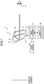
- FIG. 1 is an overall diagram illustrating an exemplary configuration of the vehicle display device according to the embodiments.
- FIG. 2 is an overall diagram illustrating the exemplary configuration of the vehicle display device according to the embodiments.
- FIG. 3 is a lateral cross-sectional view illustrating the exemplary configuration of the vehicle display device according to the embodiments.
- the vehicle display system 1 is, what is called, an electronic rearview mirror.
- the vehicle display system 1 includes a rear camera 2, a controller 3, and a vehicle display device 4.
- the driver is assumed to be the occupant of the vehicle.
- the rear camera 2 is disposed at the rear of the vehicle and takes images of the rear side of the vehicle.
- the rear camera 2 takes images of a range that includes the confirmation range for the vehicle display device 4.
- the rear camera 2 acquires images of a range including areas not displayed in the vehicle display device 4.
- the rear camera 2 has a horizontal angle of view in the range of, for example, 30° to 60° and has a vertical angle of view in the range of, for example, 5° to 20°.
- the rear camera 2 outputs video data to a video acquiring unit 31 of the controller 3.
- the controller 3 is an arithmetic processor configured using, for example, a CPU (Central Processing Unit).
- the controller 3 executes commands written in programs is stored in a memory unit (not illustrated).
- the controller 3 includes the video acquiring unit 31 and a display controller 32.
- the video acquiring unit 31 acquires video by capturing the rear view of the vehicle.
- the video data acquired by the video acquiring unit 31 represents, for example, video data in which images are continuously captured at a rate of 60 frames per second.
- the video acquiring unit 31 acquires the video data output by the rear camera 2.
- the video acquiring unit 31 clips, from the video data, a range to be displayed in the vehicle display device 4.
- the range for clipping the video data is stored in advance in the memory unit.
- the clipped range includes a range over which the driver performs visual confirmation with a conventional optical rearview mirror.
- the video acquiring unit 31 outputs the clipped video data as video signals to the display controller 32.
- the display controller 32 displays the video signals output from the video acquiring unit 31 in the vehicle display device 4.
- the vehicle display device 4 enables the driver to visually confirm the rear view of the vehicle.
- the vehicle display device 4 can be switched as a display for visually confirming a virtual image and as a display used as an optical rearview mirror.
- the vehicle display device 4 is disposed in the upper middle portion of the front side of the vehicle interior.
- the vehicle display device 4 includes a display (a display device) 5, a first concave mirror (a first mirror) 6, a second concave mirror (a second mirror) 7, a half mirror 8, and a housing 10 for housing the constituent elements.
- a distance from an eye point E of the driver to a reflected image formed by the second concave mirror 7, that is, a virtual image distance from the eye point E of the driver to the virtual image is optically extended such that it becomes longer than a distance from the eye point E of the driver to a display surface 51 of the display 5.
- the vehicle display device 4 is set to have the virtual image distance equal to or greater than approximately 800 mm.
- the virtual image distance represents one of prerequisites.
- the virtual image distance implies a condition for reducing stress on the eyes of the driver on visually confirming the virtual image.
- the virtual image distance is set to such a distance by which the visual image is easily viewable to the driver who is visually confirming several tens of meters in the front side while driving.
- the display 5 Based on the video signals output from the display controller 32, the display 5 displays the video of the rear view of the vehicle.
- Examples of the display 5 include a liquid crystal display (LCD) or an organic electro-luminescence (Organic EL) display.
- the display 5 includes the display surface 51 of the flat type.
- the display surface 51 has a landscape-oriented rectangular shape.
- the display surface 51 has a width of, for example, 180 mm in a long-side direction corresponding to the horizontal direction of a valid area, and has a width of, for example, 45 mm in the short-side direction corresponding to the vertical direction.
- the display surface 51 is disposed to be oriented upward.
- the display surface 51 is positioned to face a reflecting surface 61 of the first concave mirror 6.
- An optical axis A1 of the display 5 extends from a center of the display surface 51 in a direction orthogonal to the display surface 51.
- a central ray of the display 5 is emitted at an angle of 14° in a YZ plane in FIG. 3 , for example, and falls on the first concave mirror 6.
- the display surface 51 is disposed to be inclined with respect to the central ray falling on the first concave mirror 6.
- the display surface 51 of the display 5 is positioned within a focal length of the first concave mirror 6. Furthermore, the display surface 51 of the display 5 is positioned within a focal length of the second concave mirror 7. Moreover, the display surface 51 of the display 5 is positioned within a composite focal length of the first concave mirror 6 and the second concave mirror 7.
- the first concave mirror 6 reflects video displayed in the display 5. More specifically, the first concave mirror 6 reflects an incident light coming from the display 5 toward the second concave mirror 7.
- the first concave mirror 6 has a reflecting surface 61 formed in a concave shape for reflecting the video. Moreover, the first concave mirror 6 is bent in a concave manner toward a lower front side. Furthermore, the first concave mirror 6 is disposed above the display 5.
- the reflecting surface 61 of the first concave mirror 6 is positioned to face the display surface 51 of the display 5 and a reflecting surface 71 of the second concave mirror 7.
- the second concave mirror 7 reflects light displayed in the display 5 and reflected from the first concave mirror 6. More specifically, the second concave mirror 7 reflects the light reflected from the first concave mirror 6 toward the half mirror 8.
- the second concave mirror 7 has the reflecting surface 71 formed in a concave shape for reflecting the video. Moreover, the second concave mirror 7 is bent in a concave manner toward an upper rear side. When the vehicle display device 4 is attached to the vehicle, the second concave mirror 7 is disposed on the front side compared to the half mirror 8.
- the reflecting surface 71 of the second concave mirror 7 is positioned to face the reflecting surface 61 of the first concave mirror 6 and the half mirror 8.
- the half mirror 8 transmits the video reflected from the first concave mirror 6 and the second concave mirror 7, and reflects incident light from an opposite side of the second concave mirror 7.
- the half mirror 8 is formed to have a planar shape.
- the half mirror 8 is set to have a transmittance of 50% of the incident light. In other words, the half mirror 8 transmits 50% of the incident light and reflects the remaining 50% of the incident light.
- the half mirror 8 is positioned to face the reflecting surface 71 of the second concave mirror 7.
- the half mirror 8 is disposed on the rear side compared to the display 5, the first concave mirror 6, and the second concave mirror 7.
- the half mirror 8 is disposed opposite to the driver.
- the housing 10 is formed to have a box shape with an opening. In an internal space of the housing 10 are assembled the display 5, the first concave mirror 6, and the second concave mirror 7. The opening of the housing 10 is covered by the half mirror 8.
- the housing 10 configured in this manner is attached to the vehicle. In the embodiments, the housing 10 is positioned at a position which is looked upward by the driver.
- the vehicle display device 4 of the invention satisfies conditions (i) and (ii) and optionally one or more of conditions (iii) to (v) explained below.
- R1 represents a curvature radius of the reflecting surface 61 of the first concave mirror 6 and if R2 represents a curvature radius of the reflecting surface 71 of the second concave mirror 7, then R1 and R2 satisfy Equation 1 given below. 1 ⁇ R 2 / R 1 ⁇ 2
- the condition (i) is set to define a ratio of the curvature radius of the first concave mirror 6 to the curvature radius of the second concave mirror 7.
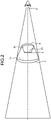
- FIG. 4 is a diagram illustrating an example of the virtual image that is visually confirmed by the driver with the vehicle display device according to the embodiments.
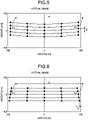
- FIG. 5 is a diagram illustrating another example of the virtual image that is visually confirmed by the driver with the vehicle display device according to the embodiments.
- FIG. 6 is a diagram illustrating still another example of the virtual image that is visually confirmed by the driver with the vehicle display device according to the embodiments.
- the explanation is given under the assumption that a rectangular video is displayed on the display surface 51 of the display 5.
- the virtual image that does not have any optical distortion is rectangular in shape in an identical manner to the video displayed on the display surface 51 of the display 5.
- the trapezoidal distortion becomes a positive value.
- the shape of the distortion is a shape in which the length of the upper base and the length of the lower base of the trapezoid satisfy (upper base) ⁇ (lower base)
- the trapezoidal distortion becomes a negative value.
- the condition (ii) is set to define a bending configuration for a light path formed due to the first concave mirror 6 and the second concave mirror 7.
- the entire vehicle display device 4, that is, the housing 10 can be downsized and deterioration in the image quality due to the inclined incidence on the first concave mirror 6 and the second concave mirror 7 can be suppressed.
- i1+i2 falls below the lower limit of the condition (ii)
- a volume of the housing 10 is increased.
- i2+i3 exceeds the upper limit of the condition (ii)
- aberration due to the first concave mirror 6 and the second concave mirror 7 is increased.
- the curvature radius R1 of the reflecting surface 61 of the first concave mirror 6 satisfies Equation 4 given below. 300 mm ⁇ R1 ⁇ 600 mm
- the curvature radius R1 of the reflecting surface 61 of the first concave mirror 6 satisfies Equation 5 given below. 360 mm ⁇ R1 ⁇ 470 mm
- the condition (iii) is set to define the curvature radius of the first concave mirror 6.
- the conditions (iii) and (iv) are satisfied, the aberration can be successfully corrected while achieving downsizing of the entire optical system.
- the curvature radius R1 falls below the lower limit of the condition (iii)
- the focal length of the entire optical system becomes smaller and the aberration increases, as well as fluctuation in the image quality due to error of the optical components is increased.
- the curvature radius R1 exceeds the upper limit of the condition (iii)
- it makes the condition (i) to fall below the lower limit and the sectorial distortion shape with the center of the circular arc being located on the upper side is increased.
- the focal length of the entire optical system increases, it becomes difficult to achieve downsizing of the housing 10.
- the condition (iv) is set to define a magnification of the video.
- the condition (iv) is satisfied, the aberration can be successfully corrected while achieving downsizing of the entire optical system.
- Yv/Yp falls below the lower limit of the condition (iv)
- a sufficiently magnified video cannot be obtained.
- a virtual image cannot be obtained.
- Yv/Yp exceeds the upper limit of the condition (iv)
- the aberration of the virtual image increases and it particularly becomes difficult to correct the distortion.
- the display surface 51 of the display 5 is disposed to be parallel to an optical axis A2 joining the eye point E of the driver and the virtual image.
- the condition (v) is set to define a installation direction of the display 5 in the housing 10. Moreover, the condition (v) represents a prerequisite for achieving downsizing of the housing 10.
- the vehicle display system 1 is installed as a substitute for a conventional optical rearview mirror, field of view on the front side may get blocked due to an increase in a size of the housing 10. Hence, it is desirable to downsize the housing 10.
- the short-side direction of the rectangular display surface 51 of the display 5 is parallel to the optical axis A2 joining the eye point E and the virtual image.
- the short-side direction is assumed to be a direction from a side of the opening of the housing 10 toward the second concave mirror 7.
- the display surface 51 of the display 5 is disposed to be oriented upward and along the direction parallel to the optical axis A2 running from the second concave mirror 7 toward the eye point E of the driver, and is disposed to be inclined with respect to the central ray that falls on the first concave mirror 6 from the display surface 51 of the display 5.
- the vehicle display device 4 configured in the manner described above, by varying the angle with respect to the vertical direction, it becomes possible to switch it as a display for visually confirming a virtual image and as a display used as an optical rearview mirror. More specifically, on visually confirming the virtual image with the vehicle display system 1, the driver can visually confirm, as the virtual image, the video in the display 5 obtained as a result of reflection from the second concave mirror 7 and transmission through the half mirror 8. Since the half mirror 8 is oriented toward the upper rear side, the reflected video from the half mirror 8 as viewed by the driver is located in the upper rear side inside the vehicle interior, and thus there is less influence on a visibility of the video displayed in the display 5. At that time, the driver can visually confirm the virtual image based on the video displayed in the display 5.
- the half mirror 8 reflects the incident light from the rear side of the vehicle. At that time, in an identical manner to an optical rearview mirror, the rear view of the vehicle is displayed therein.
- the rear camera 2 outputs the captured video data of the rear view of the vehicle obtained to the video acquiring unit 31 of the controller 3.
- the video acquiring unit 31 acquires the video data from the rear camera 2 and outputs it to the display controller 32.
- the display controller 32 outputs the video data as video signals to the display 5 of the vehicle display device 4.
- the display 5 displays, on the display surface 51, the video of the rear view of the vehicle based on the video signals.
- the display 5 in which the video is displayed emits light.
- the emitted light then falls on the first concave mirror 6.
- the incident light on the first concave mirror 6 is reflected toward the second concave mirror 7.
- the light reflected on the first concave mirror 6 falls on the second concave mirror 7.
- the incident light on the second concave mirror 7 is reflected toward the half mirror 8.
- the light reflected from the second concave mirror 7 falls on the half mirror 8.
- the incident light on the half mirror 8 passes through the half mirror 8 and reaches the driver.
- the driver visually confirms the virtual image.
- the curvature radius R1 of the reflecting surface 61 of the first concave mirror 6 is equal to 410.747 mm
- the curvature radius R2 of the reflecting surface 71 of the second concave mirror 7 is equal to 611.761 mm
- the incidence angle i1 is equal to 24.5°
- the incidence angle i2 is equal to 27.6°.
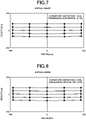
- FIG. 7 is a diagram illustrating an example of the virtual image that is visually confirmed by the driver according to the first embodiment.
- the curvature distortion is equal to 0.65% and the trapezoidal distortion is equal to -0.16%.
- the curvature radius R1 of the reflecting surface 61 of the first concave mirror 6 is equal to 420.000 mm
- the curvature radius R2 of the reflecting surface 71 of the second concave mirror 7 is equal to 600.000 mm
- the incidence angle i1 is equal to 24.5°
- the incidence angle i2 is equal to 27.6°.
- FIG. 8 is a diagram illustrating an example of the virtual image that is visually confirmed by the driver according to the second embodiment.
- the curvature distortion is equal to 0.79% and the trapezoidal distortion is equal to 0.01%.
- the curvature radius R1 of the reflecting surface 61 of the first concave mirror 6 is equal to 450.000 mm
- the curvature radius R2 of the reflecting surface 71 of the second concave mirror 7 is equal to 568.130 mm
- the incidence angle i1 is equal to 24.5°
- the incidence angle i2 is equal to 27.6°.
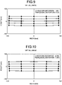
- FIG. 9 is a diagram illustrating an example of the virtual image that is visually confirmed by the driver according to the third embodiment.
- the curvature distortion is equal to 1.18% and the trapezoidal distortion is equal to 0.52%.
- the curvature radius R1 of the reflecting surface 61 of the first concave mirror 6 is equal to 370.000 mm
- the curvature radius R2 of the reflecting surface 71 of the second concave mirror 7 is equal to 679.810 mm
- the incidence angle i1 is equal to 24.5°
- the incidence angle i2 is equal to 27.6°.
- FIG. 10 is a diagram illustrating an example of the virtual image that is visually confirmed by the driver according to the fourth embodiment.
- the curvature distortion is equal to -0.04% and the trapezoidal distortion is equal to -1.06%.
- the curvature radius R1 of the reflecting surface 61 of the first concave mirror 6 is equal to 310.000 mm
- the curvature radius R2 of the reflecting surface 71 of the second concave mirror 7 is equal to 840.889 mm
- the incidence angle i1 is equal to 24.5°
- the incidence angle i2 is equal to 27.6°.
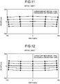
- FIG. 11 is a diagram illustrating an example of the virtual image that is visually confirmed by the driver according to the first comparative example.
- the curvature distortion is equal to -1.30% and the trapezoidal distortion is equal to -2.98%.
- the first comparative example there is an increase in the curvature distortion and the trapezoidal distortion as compared to the fourth embodiment.
- the curvature radius R1 of the reflecting surface 61 of the first concave mirror 6 is equal to 518.597 mm
- the curvature radius R2 of the reflecting surface 71 of the second concave mirror 7 is equal to 518.597 mm
- the incidence angle i1 is equal to 24.5°
- the incidence angle i2 is equal to 27.6°.
- FIG. 12 is a diagram illustrating an example of the virtual image that is visually confirmed by the driver according to the second comparative example.
- the curvature distortion is equal to 1.86% and the trapezoidal distortion is equal to 1.44%.
- the second comparative example there is an increase in the curvature distortion and the trapezoidal distortion as compared to the first to fourth embodiments.
- the light path in the housing 10 is secured in the vertical direction.
- the optical axis A2 that joins the eye point E of the driver and the virtual image in a depth direction of the housing 10 can be shortened in length, thereby enabling achieving downsizing of the housing 10.
- FIG. 13 is an overall diagram of an exemplary configuration of the conventional vehicle display device.
- FIG. 14 is a diagram illustrating an example of the virtual image that is visually confirmed by the driver with the conventional vehicle display device.
- the vehicle display device 100 includes a display 101, a half mirror 102, and the concave mirror 103.
- the light emitted in the display 101 reflects on the half mirror 102 and falls on the concave mirror 103.
- the incident light on the concave mirror 103 is reflected toward the half mirror 102.
- the incident light on the half mirror 102 passes through the half mirror 102 and reaches the driver.
- the distortion of the virtual image is suppressed.
- the length in the depth direction of the housing 110 increases, thereby resulting in an increase in the size of the housing 110.
- the entire vehicle display device 4, that is, the housing 10 can be downsized, and it becomes possible to suppress the deterioration in the image quality due to the inclined incidence of light on the first concave mirror 6 and the second concave mirror 7.
- the entire vehicle display device 4 that is, the housing 10 can be downsized, and it becomes possible to suppress the deterioration in the image quality due to the inclined incidence of light on the first concave mirror 6 and the second concave mirror 7.
- i1+i2 satisfies the lower limit of the condition (ii)
- i1+i2 satisfies the upper limit of the condition (ii)
- the aberration can be successfully corrected while achieving downsizing of the entire optical system.
- the curvature radius R1 satisfies the lower limit of the condition (iii)
- the curvature radius R1 satisfies the upper limit of the condition (iii)
- the display surface 51 of the display 5 is disposed to be inclined with respect to the central ray that falls on the first concave mirror 6 from the display surface 51.
- the display surface 51 reflects some of the incident light in a different direction from the direction of incidence, the reflected light does not reach the driver as an optical feedback. As a result, it becomes possible to suppress a deterioration in the visibility of the displayed images due to the optical feedback.
- the display surface 51 of the display 5 is disposed to be orthogonal to the central ray that falls on the first concave mirror 6 from the display surface 51, the ray of the sun falling on the vehicle display device 4 from behind fall on the display surface 51 and get partially reflected. Then, the reflected light travels the light path of incidence in the opposite direction, gets reflected on the second concave mirror 7 and on the first concave mirror 6 in this order, passes through the half mirror 8, and reaches the driver as the optical feedback. That may result in the deterioration in the visibility of the displayed images.
- constituent elements described above include constituent elements that may easily occur to one skilled in the art and include equivalent constituent elements. Moreover, the constituent elements described above can be appropriately combined.
- the half mirror 8 can be substituted with a glass plate that includes a polarizer having identical functions to the half mirror 8.
- the display 5, the half mirror 8, the first concave mirror 6, the second concave mirror 7, and the housing 10 can be installed to be embedded as an optical unit in a front ceiling or a dashboard of the vehicle.
Landscapes
- Engineering & Computer Science (AREA)
- Mechanical Engineering (AREA)
- Multimedia (AREA)
- Physics & Mathematics (AREA)
- General Physics & Mathematics (AREA)
- Optics & Photonics (AREA)
- Fittings On The Vehicle Exterior For Carrying Loads, And Devices For Holding Or Mounting Articles (AREA)
- Instrument Panels (AREA)
- Optical Elements Other Than Lenses (AREA)
- Closed-Circuit Television Systems (AREA)
Description
- The present invention relates to a vehicle display device and a vehicle display system.
- As a substitute for a conventional optical rearview mirror that reflects a rear view of a vehicle and enables an occupant of the vehicle to visually confirm the rear view of the vehicle, a technology is known that is related to an electronic mirror which displays, in a display, video captured by a camera for capturing the rear view of the vehicle and enables the occupant of the vehicle to visually confirm the rear view of the vehicle (for example, see
JP 5 286 750 B2 - Further, reference is made to
EP 0 450 553 A2 - In an identical manner to a conventional optical rearview mirror, the electronic mirror is disposed in an upper middle portion at a front of the vehicle interior. Hence, it is desirable that the electronic mirror is downsized in order to avoid blocking field of view on the front side. Moreover, in order to enhance visibility, it is desirable to suppress occurrence of distortion.
- The present invention is made in view of the issues mentioned above, and it is an object of the present invention to provide a vehicle display device and a vehicle display system which have a compact configuration and in which the occurrence of distortion is suppressed.
- According to the invention, there is provided a vehicle display device as set forth in the appended claims. The vehicle display device comprises: a display configured to display a video; a first concave mirror having a reflecting surface formed in a concave shape configured to reflect the video displayed in the display; and a second concave mirror having a reflecting surface formed in a concave shape configured to reflect the video reflected on the first mirror, wherein a display surface of the display is positioned within a composite focal length of the first mirror and the second mirror; a distance from eye point of occupant of vehicle to a reflecting image formed by the second mirror is optically extended such that it becomes longer than a distance from the eye point of the occupant to a display surface of the display; R1 and R2 satisfy 1.1<R2/R1<2 wherein R1 represents a curvature radius of the reflecting surface of the first mirror and R2 represents a curvature radius of the reflecting surface of the second mirror; and i1 and i2 satisfy 30°≤i1+i2≤70° wherein i1 represents an incidence angle of central ray from the display onto the first mirror and i2 represents an incidence angle of central ray from the first mirror onto the second mirror.
- According to one aspect, there is provided a vehicle display system comprising: the vehicle display device described above; a rear camera configured to capture a rear view of the vehicle; and a controller configured to acquire a video captured by the rear camera and displays the captured video in the display.
- According to the present invention, it becomes possible to suppress the occurrence of distortion even with a compact configuration.
-
-
FIG. 1 is an overall diagram illustrating an exemplary configuration of a vehicle display device according to embodiments. -
FIG. 2 is an overall diagram illustrating the exemplary configuration of the vehicle display device according to the embodiments. -
FIG. 3 is a lateral cross-sectional view illustrating the exemplary configuration of the vehicle display device according to the embodiments. -
FIG. 4 is a diagram illustrating an example of a virtual image that is visually confirmed by a driver with the vehicle display device according to the embodiments. -
FIG. 5 is a diagram illustrating another example of the virtual image that is visually confirmed by the driver with the vehicle display device according to the embodiments. -
FIG. 6 is a diagram illustrating still another example of the virtual image that is visually confirmed by the driver with the vehicle display device according to the embodiments. -
FIG. 7 is a diagram illustrating an example of the virtual image that is visually confirmed by the driver according to a first embodiment. -
FIG. 8 is a diagram illustrating an example of the virtual image that is visually confirmed by the driver according to a second embodiment. -
FIG. 9 is a diagram illustrating an example of the virtual image that is visually confirmed by the driver according to a third embodiment. -
FIG. 10 is a diagram illustrating an example of the virtual image that is visually confirmed by the driver according to a fourth embodiment. -
FIG. 11 is a diagram illustrating an example of the virtual image that is visually confirmed by the driver according to a first comparative example. -
FIG. 12 is a diagram illustrating an example of the virtual image that is visually confirmed by the driver according to a second comparative example. -
FIG. 13 is an overall diagram of an exemplary configuration of a conventional vehicle display device. -
FIG. 14 is a diagram illustrating an example of a virtual image that is visually confirmed by the driver with the conventional vehicle display device. - Exemplary embodiments of a vehicle display system 1 according to the present invention are described below in detail with reference to the accompanying drawings. However, the present invention is not limited by the embodiments described below.
- In the following explanation, a longitudinal direction represents a travelling direction of the vehicle in a straight line. A front side in the travelling direction is treated as a "front" of the longitudinal direction, and a rear side in the travelling direction is treated as a "rear" of the longitudinal direction. The lateral direction represents a direction that is horizontally orthogonal to the longitudinal direction. With reference to the direction toward the "front" of the longitudinal direction, a left-hand side represents the "left" and a right-hand side represents the "right". A vertical direction represents a direction that is orthogonal to the longitudinal direction and the lateral direction. Thus, the longitudinal direction, the lateral direction, and the vertical direction are three-dimensionally orthogonal to each other.
- The vehicle display system 1 is installed in a vehicle and displays a rear view of the vehicle.
FIG. 1 is an overall diagram illustrating an exemplary configuration of the vehicle display device according to the embodiments.FIG. 2 is an overall diagram illustrating the exemplary configuration of the vehicle display device according to the embodiments.FIG. 3 is a lateral cross-sectional view illustrating the exemplary configuration of the vehicle display device according to the embodiments. - As illustrated in
FIGS. 1 to 3 , the vehicle display system 1 is, what is called, an electronic rearview mirror. The vehicle display system 1 includes a rear camera 2, a controller 3, and avehicle display device 4. In the embodiments, the driver is assumed to be the occupant of the vehicle. - The rear camera 2 is disposed at the rear of the vehicle and takes images of the rear side of the vehicle. The rear camera 2 takes images of a range that includes the confirmation range for the
vehicle display device 4. Moreover, the rear camera 2 acquires images of a range including areas not displayed in thevehicle display device 4. The rear camera 2 has a horizontal angle of view in the range of, for example, 30° to 60° and has a vertical angle of view in the range of, for example, 5° to 20°. The rear camera 2 outputs video data to avideo acquiring unit 31 of the controller 3. - The controller 3 is an arithmetic processor configured using, for example, a CPU (Central Processing Unit). The controller 3 executes commands written in programs is stored in a memory unit (not illustrated). The controller 3 includes the
video acquiring unit 31 and adisplay controller 32. - The
video acquiring unit 31 acquires video by capturing the rear view of the vehicle. The video data acquired by thevideo acquiring unit 31 represents, for example, video data in which images are continuously captured at a rate of 60 frames per second. In the embodiments, thevideo acquiring unit 31 acquires the video data output by the rear camera 2. Then, thevideo acquiring unit 31 clips, from the video data, a range to be displayed in thevehicle display device 4. The range for clipping the video data is stored in advance in the memory unit. The clipped range includes a range over which the driver performs visual confirmation with a conventional optical rearview mirror. Subsequently, thevideo acquiring unit 31 outputs the clipped video data as video signals to thedisplay controller 32. - The
display controller 32 displays the video signals output from thevideo acquiring unit 31 in thevehicle display device 4. - The
vehicle display device 4 enables the driver to visually confirm the rear view of the vehicle. In the embodiments, thevehicle display device 4 can be switched as a display for visually confirming a virtual image and as a display used as an optical rearview mirror. In the embodiments, thevehicle display device 4 is disposed in the upper middle portion of the front side of the vehicle interior. Thevehicle display device 4 includes a display (a display device) 5, a first concave mirror (a first mirror) 6, a second concave mirror (a second mirror) 7, ahalf mirror 8, and ahousing 10 for housing the constituent elements. In thevehicle display device 4, a distance from an eye point E of the driver to a reflected image formed by the secondconcave mirror 7, that is, a virtual image distance from the eye point E of the driver to the virtual image is optically extended such that it becomes longer than a distance from the eye point E of the driver to adisplay surface 51 of thedisplay 5. In the embodiments, thevehicle display device 4 is set to have the virtual image distance equal to or greater than approximately 800 mm. - Herein, the virtual image distance represents one of prerequisites. The virtual image distance implies a condition for reducing stress on the eyes of the driver on visually confirming the virtual image. The virtual image distance is set to such a distance by which the visual image is easily viewable to the driver who is visually confirming several tens of meters in the front side while driving.
- Based on the video signals output from the
display controller 32, thedisplay 5 displays the video of the rear view of the vehicle. Examples of thedisplay 5 include a liquid crystal display (LCD) or an organic electro-luminescence (Organic EL) display. Thedisplay 5 includes thedisplay surface 51 of the flat type. - The
display surface 51 has a landscape-oriented rectangular shape. In the embodiments, thedisplay surface 51 has a width of, for example, 180 mm in a long-side direction corresponding to the horizontal direction of a valid area, and has a width of, for example, 45 mm in the short-side direction corresponding to the vertical direction. When thevehicle display device 4 is attached to the vehicle, thedisplay surface 51 is disposed to be oriented upward. Moreover, thedisplay surface 51 is positioned to face a reflectingsurface 61 of the firstconcave mirror 6. - An optical axis A1 of the
display 5 extends from a center of thedisplay surface 51 in a direction orthogonal to thedisplay surface 51. In the embodiments, when a video is being displayed, a central ray of thedisplay 5 is emitted at an angle of 14° in a YZ plane inFIG. 3 , for example, and falls on the firstconcave mirror 6. In other words, in the embodiments, thedisplay surface 51 is disposed to be inclined with respect to the central ray falling on the firstconcave mirror 6. - Moreover, the
display surface 51 of thedisplay 5 is positioned within a focal length of the firstconcave mirror 6. Furthermore, thedisplay surface 51 of thedisplay 5 is positioned within a focal length of the secondconcave mirror 7. Moreover, thedisplay surface 51 of thedisplay 5 is positioned within a composite focal length of the firstconcave mirror 6 and the secondconcave mirror 7. - The first
concave mirror 6 reflects video displayed in thedisplay 5. More specifically, the firstconcave mirror 6 reflects an incident light coming from thedisplay 5 toward the secondconcave mirror 7. The firstconcave mirror 6 has a reflectingsurface 61 formed in a concave shape for reflecting the video. Moreover, the firstconcave mirror 6 is bent in a concave manner toward a lower front side. Furthermore, the firstconcave mirror 6 is disposed above thedisplay 5. The reflectingsurface 61 of the firstconcave mirror 6 is positioned to face thedisplay surface 51 of thedisplay 5 and a reflectingsurface 71 of the secondconcave mirror 7. - The second
concave mirror 7 reflects light displayed in thedisplay 5 and reflected from the firstconcave mirror 6. More specifically, the secondconcave mirror 7 reflects the light reflected from the firstconcave mirror 6 toward thehalf mirror 8. The secondconcave mirror 7 has the reflectingsurface 71 formed in a concave shape for reflecting the video. Moreover, the secondconcave mirror 7 is bent in a concave manner toward an upper rear side. When thevehicle display device 4 is attached to the vehicle, the secondconcave mirror 7 is disposed on the front side compared to thehalf mirror 8. The reflectingsurface 71 of the secondconcave mirror 7 is positioned to face the reflectingsurface 61 of the firstconcave mirror 6 and thehalf mirror 8. - The
half mirror 8 transmits the video reflected from the firstconcave mirror 6 and the secondconcave mirror 7, and reflects incident light from an opposite side of the secondconcave mirror 7. Thehalf mirror 8 is formed to have a planar shape. Moreover, thehalf mirror 8 is set to have a transmittance of 50% of the incident light. In other words, thehalf mirror 8 transmits 50% of the incident light and reflects the remaining 50% of the incident light. Thehalf mirror 8 is positioned to face the reflectingsurface 71 of the secondconcave mirror 7. When thevehicle display device 4 is attached to the vehicle, thehalf mirror 8 is disposed on the rear side compared to thedisplay 5, the firstconcave mirror 6, and the secondconcave mirror 7. Moreover, when thevehicle display device 4 is attached to the vehicle, thehalf mirror 8 is disposed opposite to the driver. - The
housing 10 is formed to have a box shape with an opening. In an internal space of thehousing 10 are assembled thedisplay 5, the firstconcave mirror 6, and the secondconcave mirror 7. The opening of thehousing 10 is covered by thehalf mirror 8. Thehousing 10 configured in this manner is attached to the vehicle. In the embodiments, thehousing 10 is positioned at a position which is looked upward by the driver. - The
vehicle display device 4 of the invention satisfies conditions (i) and (ii) and optionally one or more of conditions (iii) to (v) explained below. - If R1 represents a curvature radius of the reflecting
surface 61 of the firstconcave mirror 6 and if R2 represents a curvature radius of the reflectingsurface 71 of the secondconcave mirror 7, then R1 and R2 satisfy Equation 1 given below.
- The condition (i) is set to define a ratio of the curvature radius of the first
concave mirror 6 to the curvature radius of the secondconcave mirror 7. When the condition (i) gets satisfied, it becomes possible to successfully correct optical distortion in the virtual image that is visually confirmed by the driver. - The following explanation with reference to
FIGS. 4 to 6 is given about the virtual image that is visually confirmed by the driver.FIG. 4 is a diagram illustrating an example of the virtual image that is visually confirmed by the driver with the vehicle display device according to the embodiments.FIG. 5 is a diagram illustrating another example of the virtual image that is visually confirmed by the driver with the vehicle display device according to the embodiments.FIG. 6 is a diagram illustrating still another example of the virtual image that is visually confirmed by the driver with the vehicle display device according to the embodiments. Herein, the explanation is given under the assumption that a rectangular video is displayed on thedisplay surface 51 of thedisplay 5. - As illustrated in
FIG. 4 , the virtual image that does not have any optical distortion is rectangular in shape in an identical manner to the video displayed on thedisplay surface 51 of thedisplay 5. - As illustrated in
FIG. 5 , when R2/R1 falls below the lower limit of the condition (i), there occurs an increase in the curvature distortion. That results in a sectorial distortion shape with a center of the circular arc being located on the upper side, and it becomes difficult to correct the optical distortion. The curvature distortion is calculated using (B/A)×100[%]. As illustrated inFIG. 5 , when the shape of the distortion is a shape in which the center of the circular arc is located on the upper side, the curvature distortion becomes a positive value. On the other hand, when the shape of the distortion is a shape in which the center of the circular arc is located on the lower side, the curvature distortion becomes a negative value. - As illustrated in
FIG. 6 , when R2/R1 exceeds the upper limit of the condition (i), there occurs an increase in the trapezoidal distortion. In that case, the length of bases of the trapezoid satisfies a condition (lower base)<(upper base). In order to correct the trapezoidal distortion, an installation direction of thedisplay 5 needs to be adjusted by deviating from a condition (v) that represents one of the prerequisites, thereby making it difficult to achieve downsizing of thevehicle display device 4. The trapezoidal distortion is calculated using (C/A)×100[%]. As illustrated inFIG. 6 , when the shape of the distortion is a shape in which the length of the upper base and the length of the lower base of the trapezoid satisfy (lower base)<(upper base), the trapezoidal distortion becomes a positive value. On the other hand, when the shape of the distortion is a shape in which the length of the upper base and the length of the lower base of the trapezoid satisfy (upper base)<(lower base), the trapezoidal distortion becomes a negative value. - If i1 represents an incidence angle of the central ray from the
display 5 to the firstconcave mirror 6 and if i2 represents an incidence angle of the central ray from the firstconcave mirror 6 to the secondconcave mirror 7, the incidence angles i1 and i2 satisfy Equation 2 given below.
- Moreover, it is desirable that the incidence angles i1 and i2 satisfy Equation 3 given below.

- The condition (ii) is set to define a bending configuration for a light path formed due to the first
concave mirror 6 and the secondconcave mirror 7. As a result of satisfying the condition (ii), the entirevehicle display device 4, that is, thehousing 10 can be downsized and deterioration in the image quality due to the inclined incidence on the firstconcave mirror 6 and the secondconcave mirror 7 can be suppressed. When i1+i2 falls below the lower limit of the condition (ii), it becomes difficult to achieve downsizing of thevehicle display device 4. Moreover, due to a mirror arrangement for securing pencil of rays from the firstconcave mirror 6 and the secondconcave mirror 7, a volume of thehousing 10 is increased. On the other hand, when i2+i3 exceeds the upper limit of the condition (ii), aberration due to the firstconcave mirror 6 and the secondconcave mirror 7 is increased. - The curvature radius R1 of the reflecting
surface 61 of the firstconcave mirror 6 satisfiesEquation 4 given below.
- Moreover, it is desirable that the curvature radius R1 of the reflecting
surface 61 of the firstconcave mirror 6 satisfiesEquation 5 given below.
- The condition (iii) is set to define the curvature radius of the first
concave mirror 6. When the conditions (iii) and (iv) are satisfied, the aberration can be successfully corrected while achieving downsizing of the entire optical system. If the curvature radius R1 falls below the lower limit of the condition (iii), then the focal length of the entire optical system becomes smaller and the aberration increases, as well as fluctuation in the image quality due to error of the optical components is increased. On the other hand, if the curvature radius R1 exceeds the upper limit of the condition (iii), it makes the condition (i) to fall below the lower limit and the sectorial distortion shape with the center of the circular arc being located on the upper side is increased. Moreover, since the focal length of the entire optical system increases, it becomes difficult to achieve downsizing of thehousing 10. - If Yv represents a magnitude in a vertical direction of the virtual image that is visually confirmed by the driver and if Yp represents a magnitude in a height direction of the video, corresponding to the vertical direction of the virtual image, that is displayed on the
display surface 51 of thedisplay 5, then the magnitudes Yv and Yp satisfyEquation 6 given below.
- Moreover, it is desirable that the magnitudes Yv and Yp satisfy
Equation 7 given below.
- The condition (iv) is set to define a magnification of the video. When the condition (iv) is satisfied, the aberration can be successfully corrected while achieving downsizing of the entire optical system. When Yv/Yp falls below the lower limit of the condition (iv), a sufficiently magnified video cannot be obtained. In other words, a virtual image cannot be obtained. When Yv/Yp exceeds the upper limit of the condition (iv), the aberration of the virtual image increases and it particularly becomes difficult to correct the distortion.
- The
display surface 51 of thedisplay 5 is disposed to be parallel to an optical axis A2 joining the eye point E of the driver and the virtual image. - The condition (v) is set to define a installation direction of the
display 5 in thehousing 10. Moreover, the condition (v) represents a prerequisite for achieving downsizing of thehousing 10. When the vehicle display system 1 is installed as a substitute for a conventional optical rearview mirror, field of view on the front side may get blocked due to an increase in a size of thehousing 10. Hence, it is desirable to downsize thehousing 10. - The condition (v), that is, the
display surface 51 of thedisplay 5 is so disposed that a direction of extension of the short side of therectangular display surface 51 is parallel to the optical axis A2 joining the eye point E of the driver and the virtual image. Thus, the short-side direction of therectangular display surface 51 of thedisplay 5 is parallel to the optical axis A2 joining the eye point E and the virtual image. Herein, the short-side direction is assumed to be a direction from a side of the opening of thehousing 10 toward the secondconcave mirror 7. Thus, thedisplay surface 51 of thedisplay 5 is disposed to be oriented upward and along the direction parallel to the optical axis A2 running from the secondconcave mirror 7 toward the eye point E of the driver, and is disposed to be inclined with respect to the central ray that falls on the firstconcave mirror 6 from thedisplay surface 51 of thedisplay 5. - In the
vehicle display device 4 configured in the manner described above, by varying the angle with respect to the vertical direction, it becomes possible to switch it as a display for visually confirming a virtual image and as a display used as an optical rearview mirror. More specifically, on visually confirming the virtual image with the vehicle display system 1, the driver can visually confirm, as the virtual image, the video in thedisplay 5 obtained as a result of reflection from the secondconcave mirror 7 and transmission through thehalf mirror 8. Since thehalf mirror 8 is oriented toward the upper rear side, the reflected video from thehalf mirror 8 as viewed by the driver is located in the upper rear side inside the vehicle interior, and thus there is less influence on a visibility of the video displayed in thedisplay 5. At that time, the driver can visually confirm the virtual image based on the video displayed in thedisplay 5. On using the vehicle display system 1 as an optical rearview mirror, by varying an angle of thehousing 10 of thevehicle display device 4 compared to that on visually confirming the virtual image, thehalf mirror 8 reflects the incident light from the rear side of the vehicle. At that time, in an identical manner to an optical rearview mirror, the rear view of the vehicle is displayed therein. - Given below is the explanation of a display method and operations for displaying a virtual image in the vehicle display system 1. Firstly, the rear camera 2 outputs the captured video data of the rear view of the vehicle obtained to the
video acquiring unit 31 of the controller 3. Thus, thevideo acquiring unit 31 acquires the video data from the rear camera 2 and outputs it to thedisplay controller 32. Then, thedisplay controller 32 outputs the video data as video signals to thedisplay 5 of thevehicle display device 4. - Subsequently, the
display 5 displays, on thedisplay surface 51, the video of the rear view of the vehicle based on the video signals. Thedisplay 5 in which the video is displayed emits light. The emitted light then falls on the firstconcave mirror 6. Subsequently, the incident light on the firstconcave mirror 6 is reflected toward the secondconcave mirror 7. Then, the light reflected on the firstconcave mirror 6 falls on the secondconcave mirror 7. Subsequently, the incident light on the secondconcave mirror 7 is reflected toward thehalf mirror 8. Then, the light reflected from the secondconcave mirror 7 falls on thehalf mirror 8. Subsequently, the incident light on thehalf mirror 8 passes through thehalf mirror 8 and reaches the driver. Thus, the driver visually confirms the virtual image. - As illustrated in Table 1, the curvature radius R1 of the reflecting
surface 61 of the firstconcave mirror 6 is equal to 410.747 mm, the curvature radius R2 of the reflectingsurface 71 of the secondconcave mirror 7 is equal to 611.761 mm, the incidence angle i1 is equal to 24.5°, and the incidence angle i2 is equal to 27.6°.Table 1 Curvature radius of each face R [mm] Coordinates of central ray in each face Incidence angle [deg] of central ray in each face X [mm] Y [mm] Z [mm] Display device ∞ 0 -32.397 -455.5000 - First concave mirror 410.747 0 38.430 -473.291 24.5 Second concave mirror 611.761 0 0 -500.000 27.6 Eye Point ∞ 0 0 0 0 Virtual image ∞ 0 0 -836.028 0 - As illustrated in Table 2, if i1+i2 is equal to 52.1, if R2/R1 is equal to 1.49, and if Yv/Yp is equal to 3.71, then the distance from the virtual image to the eye point E becomes equal to 836.028 mm.
Table 2 i1+i2 52.1 R2/R1 1.49 Yv/Yp 3.71 R1 410.747 Virtual image to EyePoint 836.028 - The following explanation with reference to
FIG. 7 is given about the distortion according to a first embodiment.FIG. 7 is a diagram illustrating an example of the virtual image that is visually confirmed by the driver according to the first embodiment. In this case, the curvature distortion is equal to 0.65% and the trapezoidal distortion is equal to -0.16%. - As illustrated in Table 3, the curvature radius R1 of the reflecting
surface 61 of the firstconcave mirror 6 is equal to 420.000 mm, the curvature radius R2 of the reflectingsurface 71 of the secondconcave mirror 7 is equal to 600.000 mm, the incidence angle i1 is equal to 24.5°, and the incidence angle i2 is equal to 27.6°.Table 3 Curvature radius of each face R [mm] Coordinates of central ray in each face Incidence angle [deg] of central ray in each face X [mm] Y [mm] Z [mm] Display device ∞ 0 -32.397 -455.500 - First concave mirror 420.000 0 38.430 -473.291 24.5 Second concave mirror 600.000 0 0 -500.00 27.6 Eye Point ∞ 0 0 0 0 Virtual image ∞ 0 0 -828.606 0 - As illustrated in Table 4, if i1+i2 is equal to 52.1, if R2/R1 is equal to 1.43, and if Yv/Yp is equal to 3.71, then the distance from the virtual image to the eye point E is equal to 828.606 mm.
Table 4 i1+i2 52.1 R2/R1 1.43 Yv/Yp 3.71 R1 420 Virtual image to EyePoint 828.606 - The following explanation with reference to
FIG. 8 is given about the distortion according to a second embodiment.FIG. 8 is a diagram illustrating an example of the virtual image that is visually confirmed by the driver according to the second embodiment. In this case, the curvature distortion is equal to 0.79% and the trapezoidal distortion is equal to 0.01%. - As illustrated in Table 5, the curvature radius R1 of the reflecting
surface 61 of the firstconcave mirror 6 is equal to 450.000 mm, the curvature radius R2 of the reflectingsurface 71 of the secondconcave mirror 7 is equal to 568.130 mm, the incidence angle i1 is equal to 24.5°, and the incidence angle i2 is equal to 27.6°.Table 5 Curvature radius of each face R [mm] Coordinates of central ray in each face Incidence angle [deg] of central ray in each face X [mm] Y [mm] Z [mm] Display device ∞ 0 -32.397 -455.500 - First concave mirror 450.000 0 38.430 -473.291 24.5 Second concave mirror 568.130 0 0 -500.00 27.6 Eye Point ∞ 0 0 0 0 Virtual image ∞ 0 0 -840.755 0 - As illustrated in Table 6, if i1+i2 is equal to 52.1, if R2/R1 is equal to 1.26, and if Yv/Yp is equal to 3.71, then the distance from the virtual image to the eye point E is equal to 840.755 mm.
Table 6 i1+i2 52.1 R2/R1 1.26 Yv/Yp 3.71 R1 450 Virtual image to EyePoint 840.755 - The following explanation with reference to
FIG. 9 is given about the distortion according to a third embodiment.FIG. 9 is a diagram illustrating an example of the virtual image that is visually confirmed by the driver according to the third embodiment. In this case, the curvature distortion is equal to 1.18% and the trapezoidal distortion is equal to 0.52%. - As illustrated in Table 7, the curvature radius R1 of the reflecting
surface 61 of the firstconcave mirror 6 is equal to 370.000 mm, the curvature radius R2 of the reflectingsurface 71 of the secondconcave mirror 7 is equal to 679.810 mm, the incidence angle i1 is equal to 24.5°, and the incidence angle i2 is equal to 27.6°.Table 7 Curvature radius of each face R [mm] Coordinates of central ray in each face Incidence angle [deg] of central ray in each face X [mm] Y [mm] Z [mm] Display device ∞ 0 -32.397 -455.500 - First concave mirror 370.000 0 38.430 -473.291 24.5 Second concave mirror 679.810 0 0 -500.00 27.6 Eye Point ∞ 0 0 0 0 Virtual image ∞ 0 0 -830.598 0 - As illustrated in Table 8, if i1+i2 is equal to 52.1, if R2/R1 is equal to 1.84, and if Yv/Yp is equal to 3.72, then the distance from the virtual image to the eye point E is equal to 830.598 mm.
Table 8 i1+i2 52.1 R2/R1 1.84 Yv/Yp 3.72 R1 370 Virtual image to EyePoint 830.598 - The following explanation with reference to
FIG. 10 is given about the distortion according to a fourth embodiment.FIG. 10 is a diagram illustrating an example of the virtual image that is visually confirmed by the driver according to the fourth embodiment. In this case, the curvature distortion is equal to -0.04% and the trapezoidal distortion is equal to -1.06%. - As illustrated in Table 9, the curvature radius R1 of the reflecting
surface 61 of the firstconcave mirror 6 is equal to 310.000 mm, the curvature radius R2 of the reflectingsurface 71 of the secondconcave mirror 7 is equal to 840.889 mm, the incidence angle i1 is equal to 24.5°, and the incidence angle i2 is equal to 27.6°.Table 9 Curvature radius of each face R [mm] Coordinates of central ray in each face Incidence angle [deg] of central ray in each face X [mm] Y [mm] Z [mm] Display device ∞ 0 -32.397 -455.500 - First concave mirror 310.000 0 38.430 -473.291 24.5 Second concave mirror 840.889 0 0 -500.00 27.6 Eye Point ∞ 0 0 0 0 Virtual image ∞ 0 0 -829.999 0 - As illustrated in Table 10, if i1+i2 is equal to 52.1, if R2/R1 is equal to 2.71, and if Yv/Yp is equal to 3.71, then the distance from the virtual image to the eye point E is equal to 829.999 mm.
Table 10 i1+i2 52.1 R2/R1 2.71 Yv/Yp 3.71 R1 310.000 Virtual image to EyePoint 829.999 - The following explanation with reference to
FIG. 11 is given about the distortion according to a first comparative example.FIG. 11 is a diagram illustrating an example of the virtual image that is visually confirmed by the driver according to the first comparative example. In this case, the curvature distortion is equal to -1.30% and the trapezoidal distortion is equal to -2.98%. Thus, in the first comparative example, there is an increase in the curvature distortion and the trapezoidal distortion as compared to the fourth embodiment. - As illustrated in Table 11, the curvature radius R1 of the reflecting
surface 61 of the firstconcave mirror 6 is equal to 518.597 mm, the curvature radius R2 of the reflectingsurface 71 of the secondconcave mirror 7 is equal to 518.597 mm, the incidence angle i1 is equal to 24.5°, and the incidence angle i2 is equal to 27.6°.Table 11 Curvature radius of each face R [mm] Coordinates of central ray in each face Incidence angle [deg] of central ray in each face X [mm] Y [mm] Z [mm] Display device ∞ 0 -32.397 -455.500 - First concave mirror 518.597 0 38.430 -473.291 24.5 Second concave mirror 518.597 0 0 -500.00 27.6 Eye Point ∞ 0 0 0 0 Virtual image ∞ 0 0 -847.298 0 - As illustrated in Table 11, if i1+i2 is equal to 52.1, if R2/R1 is equal to 1.00, and if Yv/Yp is equal to 3.71, then the distance from the virtual image to the eye point E is equal to 847.298 mm.
Table 12 i1+i2 52.1 R2/R1 1.00 Yv/Yp 3.71 R1 518.597 Virtual image to EyePoint 847.298 - The following explanation with reference to
FIG. 12 is given about the distortion according to a second comparative example.FIG. 12 is a diagram illustrating an example of the virtual image that is visually confirmed by the driver according to the second comparative example. In this case, the curvature distortion is equal to 1.86% and the trapezoidal distortion is equal to 1.44%. Thus, in the second comparative example, there is an increase in the curvature distortion and the trapezoidal distortion as compared to the first to fourth embodiments. - As described above, in the embodiments, as a result of arranging two concave mirrors, namely, the first
concave mirror 6 and the secondconcave mirror 7, the light path in thehousing 10 is secured in the vertical direction. As a result, in the embodiments, the optical axis A2 that joins the eye point E of the driver and the virtual image in a depth direction of thehousing 10 can be shortened in length, thereby enabling achieving downsizing of thehousing 10. - In contrast, explained below with reference to
FIGS. 13 and14 is avehicle display device 100 that includes a singleconcave mirror 103.FIG. 13 is an overall diagram of an exemplary configuration of the conventional vehicle display device.FIG. 14 is a diagram illustrating an example of the virtual image that is visually confirmed by the driver with the conventional vehicle display device. Thevehicle display device 100 includes adisplay 101, ahalf mirror 102, and theconcave mirror 103. The light emitted in thedisplay 101 reflects on thehalf mirror 102 and falls on theconcave mirror 103. Then, the incident light on theconcave mirror 103 is reflected toward thehalf mirror 102. Subsequently, the incident light on thehalf mirror 102 passes through thehalf mirror 102 and reaches the driver. As illustrated inFIG. 14 , in thevehicle display device 100, the distortion of the virtual image is suppressed. However, as illustrated inFIG. 13 , since the light path in ahousing 110 cannot be secured in the vertical direction, the length in the depth direction of thehousing 110 increases, thereby resulting in an increase in the size of thehousing 110. - In the embodiments, as a result of using two concave mirrors, namely, the first
concave mirror 6 and the secondconcave mirror 7, it becomes possible to share and reduce the influence of aberration occurring by reflection in the optical system. Thus, according to the embodiments, it becomes possible to reduce the distortion. - Moreover, in the embodiments, as a result of satisfying the conditions (i) to (v), it becomes possible to achieve downsizing of the
housing 10 and to suppress the occurrence of distortion. - In the embodiments, as a result of satisfying the condition (i), it becomes possible to successfully correct the optical distortion in the virtual image that is visually confirmed by the driver. In the embodiments, when R2/R1 satisfies the lower limit of the condition (i) and R1 and R2 satisfy R1≤R2, the curvature distortion can be suppressed. Moreover, in the embodiments, since R2/R1 satisfies the upper limit of the condition (i), the trapezoidal distortion can be suppressed.
- In the embodiments, as a result of satisfying the condition (ii), the entire
vehicle display device 4, that is, thehousing 10 can be downsized, and it becomes possible to suppress the deterioration in the image quality due to the inclined incidence of light on the firstconcave mirror 6 and the secondconcave mirror 7. In the embodiments, since i1+i2 satisfies the lower limit of the condition (ii), it becomes possible to downsize thevehicle display device 4. Moreover, in the embodiments, since i1+i2 satisfies the upper limit of the condition (ii), it becomes possible to suppress the aberration due to the firstconcave mirror 6 and the secondconcave mirror 7. - In the embodiments, as a result of satisfying the conditions (iii) and (iv), the aberration can be successfully corrected while achieving downsizing of the entire optical system. In the embodiments, since the curvature radius R1 satisfies the lower limit of the condition (iii), it becomes possible to suppress the aberration and to reduce the fluctuation in the image quality due to the error of the optical components. In the embodiments, since the curvature radius R1 satisfies the upper limit of the condition (iii), it becomes possible to suppress the sectorial distortion.
- In the embodiments, the
display surface 51 of thedisplay 5 is disposed to be inclined with respect to the central ray that falls on the firstconcave mirror 6 from thedisplay surface 51. According to the embodiments, when the sunlight falls on thevehicle display device 4 from behind, ray of the sun reflected from the firstconcave mirror 6 and the secondconcave mirror 7 fall on thedisplay surface 51. However, thedisplay surface 51 reflects some of the incident light in a different direction from the direction of incidence, the reflected light does not reach the driver as an optical feedback. As a result, it becomes possible to suppress a deterioration in the visibility of the displayed images due to the optical feedback. - In contrast, if the
display surface 51 of thedisplay 5 is disposed to be orthogonal to the central ray that falls on the firstconcave mirror 6 from thedisplay surface 51, the ray of the sun falling on thevehicle display device 4 from behind fall on thedisplay surface 51 and get partially reflected. Then, the reflected light travels the light path of incidence in the opposite direction, gets reflected on the secondconcave mirror 7 and on the firstconcave mirror 6 in this order, passes through thehalf mirror 8, and reaches the driver as the optical feedback. That may result in the deterioration in the visibility of the displayed images. - The constituent elements described above include constituent elements that may easily occur to one skilled in the art and include equivalent constituent elements. Moreover, the constituent elements described above can be appropriately combined.
- Meanwhile, the
half mirror 8 can be substituted with a glass plate that includes a polarizer having identical functions to thehalf mirror 8. - Moreover, the
display 5, thehalf mirror 8, the firstconcave mirror 6, the secondconcave mirror 7, and thehousing 10 can be installed to be embedded as an optical unit in a front ceiling or a dashboard of the vehicle.
Claims (5)
- A vehicle display device(4) comprising:a display (5) configured to display a video;a first concave mirror (6) having a reflecting surface (61) formed in a concave shape configured to reflect the video displayed in the display (5); anda second concave mirror (7) having a reflecting surface (71) formed in a concave shape configured to reflect the video reflected on the first concave mirror (6), whereina display surface (51) of the display (5) is positioned within a composite focal length of the first concave mirror (6) and the second concave mirror (7); anda distance from eye point of occupant of vehicle to a reflecting image formed by the second concave mirror (7) is optically extended such that it becomes longer than a distance from the eye point of the occupant to a display surface (51) of the display (5); characterized in thatR1 and R2 satisfy 1.1<R2/R1<2 wherein R1 represents a curvature radius of the reflecting surface (61) of the first concave mirror (6) and R2 represents a curvature radius of the reflecting surface (71) of the second concave mirror (7);i1 and i2 satisfy 30°≤i1+i2≤70° wherein i1 represents an incidence angle of central ray from the display (5) onto the first concave mirror (6) and i2 represents an incidence angle of central ray from the first concave mirror (5) onto the second concave mirror (7).
- The vehicle display device (4) according to claim 1, wherein the curvature radius R1 of the reflecting surface (61) of the first concave mirror (6) satisfies 300 mm≤R1≤600 mm.
- The vehicle display device (4) according to claim 1 or 2, wherein, Yv and Yp satisfy 1<Yv/Yp<10 wherein Yv represents a magnitude in a vertical direction of the video that is visually confirmed by the occupant and Yp represents a magnitude in a height direction of the video, corresponding to the vertical direction of the virtual image, that is displayed on the display surface (51).
- The vehicle display device (4) according to any one of claims 1 to 3, wherein the display surface (51) is disposed to be oriented upward and along a direction parallel to optical axis from the second concave mirror (7) toward the eye point of the occupant, and is disposed to be inclined with respect to a central ray that falls on the first concave mirror (6) from the display surface (51).
- A vehicle display system comprising:the vehicle display device (4) according to any one of claims 1 to 4;a rear camera (2) configured to capture a rear view of the vehicle; anda controller (3) configured to acquire a video captured by the rear camera (2) and to display the captured video in the display (5).
Applications Claiming Priority (2)
| Application Number | Priority Date | Filing Date | Title |
|---|---|---|---|
| JP2017229416A JP6874659B2 (en) | 2017-11-29 | 2017-11-29 | Vehicle display device and vehicle display system |
| PCT/JP2018/037069 WO2019106951A1 (en) | 2017-11-29 | 2018-10-03 | Display apparatus for vehicle and display system for vehicle |
Publications (3)
| Publication Number | Publication Date |
|---|---|
| EP3683096A1 EP3683096A1 (en) | 2020-07-22 |
| EP3683096A4 EP3683096A4 (en) | 2020-12-09 |
| EP3683096B1 true EP3683096B1 (en) | 2022-05-04 |
Family
ID=66664821
Family Applications (1)
| Application Number | Title | Priority Date | Filing Date |
|---|---|---|---|
| EP18883176.2A Active EP3683096B1 (en) | 2017-11-29 | 2018-10-03 | Display apparatus for vehicle and display system for vehicle |
Country Status (5)
| Country | Link |
|---|---|
| US (1) | US11110865B2 (en) |
| EP (1) | EP3683096B1 (en) |
| JP (1) | JP6874659B2 (en) |
| CN (1) | CN110234541B (en) |
| WO (1) | WO2019106951A1 (en) |
Families Citing this family (8)
| Publication number | Priority date | Publication date | Assignee | Title |
|---|---|---|---|---|
| JP6956359B2 (en) * | 2019-10-08 | 2021-11-02 | パナソニックIpマネジメント株式会社 | Display system and electronic mirror system equipped with it |
| DE102020128073B4 (en) * | 2019-10-30 | 2024-03-21 | Panasonic Intellectual Property Management Co., Ltd. | Display system |
| JP7002021B2 (en) * | 2020-05-12 | 2022-01-20 | パナソニックIpマネジメント株式会社 | Display device |
| JP2021182704A (en) * | 2020-05-19 | 2021-11-25 | トヨタ自動車株式会社 | Image display device |
| JP7491075B2 (en) * | 2020-06-17 | 2024-05-28 | 株式会社Jvcケンウッド | Vehicle display device |
| CN113978367B (en) * | 2021-11-16 | 2023-06-02 | 武汉华星光电技术有限公司 | Vehicle-mounted display device, vehicle-mounted display system and vehicle |
| JP7336779B1 (en) * | 2022-03-25 | 2023-09-01 | パナソニックIpマネジメント株式会社 | display system |
| JP2024140490A (en) * | 2023-03-28 | 2024-10-10 | いすゞ自動車株式会社 | Driving Support Devices |
Family Cites Families (23)
| Publication number | Priority date | Publication date | Assignee | Title |
|---|---|---|---|---|
| JPH03125623U (en) * | 1990-04-03 | 1991-12-18 | ||
| JP3204339B2 (en) * | 1992-11-04 | 2001-09-04 | 矢崎総業株式会社 | Display device for vehicles |
| JPH1152485A (en) * | 1997-08-02 | 1999-02-26 | Victor Co Of Japan Ltd | Display device for picture |
| SE516881C2 (en) * | 1999-05-31 | 2002-03-19 | Saabtech Electronics Ab | Method and apparatus for superimposing an image onto a direct external image to be presented to an observer |
| JP2001183179A (en) * | 1999-12-27 | 2001-07-06 | Nippon Seiki Co Ltd | Display device |
| US7965336B2 (en) * | 2002-11-14 | 2011-06-21 | Donnelly Corporation | Imaging system for vehicle |
| JP2007069771A (en) * | 2005-09-07 | 2007-03-22 | Denso Corp | Head-up display device for vehicle |
| WO2008050842A1 (en) * | 2006-10-27 | 2008-05-02 | Calsonic Kansei Corporation | Display device for vehicle |
| JP5286750B2 (en) * | 2007-11-16 | 2013-09-11 | 日産自動車株式会社 | Vehicle display device |
| JP2009122582A (en) * | 2007-11-19 | 2009-06-04 | Fujinon Corp | Projection optical system and head-up display apparatus |
| CN102466882A (en) * | 2010-11-18 | 2012-05-23 | 华创车电技术中心股份有限公司 | Vehicle display module with head-up and instrument display function |
| JP5903819B2 (en) * | 2011-03-22 | 2016-04-13 | 日本精機株式会社 | Field sequential image display device |
| JP5741251B2 (en) * | 2011-06-28 | 2015-07-01 | 日本精機株式会社 | Virtual image display device |
| CN102910127A (en) * | 2012-11-20 | 2013-02-06 | 刘仁国 | Method for horizontally displaying global positioning system (GPS) radar road condition data information |
| JP6237123B2 (en) * | 2012-12-21 | 2017-11-29 | 株式会社リコー | Two-dimensional image display device, optical scanning device for two-dimensional image display device, scanned surface element, and moving body |
| JP5682692B2 (en) * | 2012-12-21 | 2015-03-11 | 株式会社リコー | Image display device |
| JP2015069081A (en) * | 2013-09-30 | 2015-04-13 | 日本精機株式会社 | Projection type display device |
| FR3030064B1 (en) * | 2014-12-10 | 2018-03-30 | Valeo Comfort And Driving Assistance | HIGH HEAD DISPLAY FOR MOTOR VEHICLE |
| JP2017021079A (en) * | 2015-07-07 | 2017-01-26 | 株式会社リコー | Microlens array and image display device |
| JP6578547B2 (en) | 2015-07-23 | 2019-09-25 | 株式会社ホンダロック | Rear view device |
| KR101759945B1 (en) * | 2015-08-05 | 2017-07-20 | 엘지전자 주식회사 | Display Device |
| DE102016101997A1 (en) * | 2016-02-04 | 2017-08-10 | SMR Patents S.à.r.l. | Lighting device and rearview device for vehicles |
| JP6870447B2 (en) * | 2016-05-20 | 2021-05-12 | 株式会社リコー | HUD device, vehicle device, information display method. |
-
2017
- 2017-11-29 JP JP2017229416A patent/JP6874659B2/en active Active
-
2018
- 2018-10-03 EP EP18883176.2A patent/EP3683096B1/en active Active
- 2018-10-03 WO PCT/JP2018/037069 patent/WO2019106951A1/en not_active Ceased
- 2018-10-03 CN CN201880006098.8A patent/CN110234541B/en active Active
-
2020
- 2020-04-03 US US16/839,093 patent/US11110865B2/en active Active
Also Published As
| Publication number | Publication date |
|---|---|
| EP3683096A4 (en) | 2020-12-09 |
| WO2019106951A1 (en) | 2019-06-06 |
| US20200231093A1 (en) | 2020-07-23 |
| CN110234541B (en) | 2022-07-26 |
| EP3683096A1 (en) | 2020-07-22 |
| CN110234541A (en) | 2019-09-13 |
| US11110865B2 (en) | 2021-09-07 |
| JP6874659B2 (en) | 2021-05-19 |
| JP2019098832A (en) | 2019-06-24 |
Similar Documents
| Publication | Publication Date | Title |
|---|---|---|
| EP3683096A1 (en) | Display apparatus for vehicle and display system for vehicle | |
| CN106997096B (en) | Head-up display device | |
| US11448877B2 (en) | Projection optical system and head-up display | |
| US11175500B2 (en) | Display device and display method of the same | |
| CN107238927B (en) | Projection display equipment for vehicles | |
| EP3096178A1 (en) | Display apparatus | |
| US20180081174A1 (en) | Projection optical system and head-up display apparatus using the same | |
| EP2944986B1 (en) | Image display apparatus and image display system | |
| EP3276396A1 (en) | Head-up display and moving body equipped with head-up display | |
| US10814723B2 (en) | Projection optical system, and head-up display device | |
| US20190299858A1 (en) | Display system, electronic mirror system, moving vehicle, and display method | |
| US10025097B2 (en) | Head-up display and moving body equipped with head-up display | |
| JP2018132684A (en) | Head-up display device | |
| JPWO2016038767A1 (en) | Head-up display and moving body | |
| US20230367120A1 (en) | Vehicle display apparatus | |
| CN113296273B (en) | Optical system | |
| JP7043649B2 (en) | Image display device | |
| US20180370362A1 (en) | Vehicle display device | |
| WO2018186149A1 (en) | Head-up display system, and mobile object provided with head-up display system | |
| CN207216150U (en) | HUD and means of transport | |
| JP2008203550A (en) | Head-mounted display device | |
| JP2021035808A (en) | Electronic mirror device | |
| US11433817B2 (en) | Display apparatus | |
| JP2021035807A (en) | Electronic mirror device |
Legal Events
| Date | Code | Title | Description |
|---|---|---|---|
| STAA | Information on the status of an ep patent application or granted ep patent |
Free format text: STATUS: THE INTERNATIONAL PUBLICATION HAS BEEN MADE |
|
| PUAI | Public reference made under article 153(3) epc to a published international application that has entered the european phase |
Free format text: ORIGINAL CODE: 0009012 |
|
| STAA | Information on the status of an ep patent application or granted ep patent |
Free format text: STATUS: REQUEST FOR EXAMINATION WAS MADE |
|
| 17P | Request for examination filed |
Effective date: 20200414 |
|
| AK | Designated contracting states |
Kind code of ref document: A1 Designated state(s): AL AT BE BG CH CY CZ DE DK EE ES FI FR GB GR HR HU IE IS IT LI LT LU LV MC MK MT NL NO PL PT RO RS SE SI SK SM TR |
|
| AX | Request for extension of the european patent |
Extension state: BA ME |
|
| A4 | Supplementary search report drawn up and despatched |
Effective date: 20200825 |
|
| RIC1 | Information provided on ipc code assigned before grant |
Ipc: B60R 1/04 20060101ALI20200819BHEP Ipc: G02B 27/01 20060101AFI20200819BHEP Ipc: B60R 11/02 20060101ALI20200819BHEP Ipc: B60R 1/00 20060101ALI20200819BHEP |
|
| RA4 | Supplementary search report drawn up and despatched (corrected) |
Effective date: 20200825 |
|
| REG | Reference to a national code |
Ref country code: DE Ref legal event code: R079 Ref document number: 602018035189 Country of ref document: DE Free format text: PREVIOUS MAIN CLASS: B60R0011020000 Ipc: G02B0027010000 |
|
| RIC1 | Information provided on ipc code assigned before grant |
Ipc: B60R 1/00 20060101ALI20210111BHEP Ipc: B60R 1/04 20060101ALI20210111BHEP Ipc: B60R 11/02 20060101ALI20210111BHEP Ipc: G02B 27/01 20060101AFI20210111BHEP |
|
| DAV | Request for validation of the european patent (deleted) | ||
| DAX | Request for extension of the european patent (deleted) | ||
| RIN1 | Information on inventor provided before grant (corrected) |
Inventor name: KOBAYASHI, MANABU Inventor name: WADA, YUKI |
|
| GRAP | Despatch of communication of intention to grant a patent |
Free format text: ORIGINAL CODE: EPIDOSNIGR1 |
|
| STAA | Information on the status of an ep patent application or granted ep patent |
Free format text: STATUS: GRANT OF PATENT IS INTENDED |
|
| GRAJ | Information related to disapproval of communication of intention to grant by the applicant or resumption of examination proceedings by the epo deleted |
Free format text: ORIGINAL CODE: EPIDOSDIGR1 |
|
| GRAP | Despatch of communication of intention to grant a patent |
Free format text: ORIGINAL CODE: EPIDOSNIGR1 |
|
| INTG | Intention to grant announced |
Effective date: 20211119 |
|
| INTG | Intention to grant announced |
Effective date: 20211129 |
|
| GRAS | Grant fee paid |
Free format text: ORIGINAL CODE: EPIDOSNIGR3 |
|
| GRAA | (expected) grant |
Free format text: ORIGINAL CODE: 0009210 |
|
| STAA | Information on the status of an ep patent application or granted ep patent |
Free format text: STATUS: THE PATENT HAS BEEN GRANTED |
|
| AK | Designated contracting states |
Kind code of ref document: B1 Designated state(s): AL AT BE BG CH CY CZ DE DK EE ES FI FR GB GR HR HU IE IS IT LI LT LU LV MC MK MT NL NO PL PT RO RS SE SI SK SM TR |
|
| REG | Reference to a national code |
Ref country code: GB Ref legal event code: FG4D |
|
| REG | Reference to a national code |
Ref country code: CH Ref legal event code: EP |
|
| REG | Reference to a national code |
Ref country code: AT Ref legal event code: REF Ref document number: 1489680 Country of ref document: AT Kind code of ref document: T Effective date: 20220515 |
|
| REG | Reference to a national code |
Ref country code: DE Ref legal event code: R096 Ref document number: 602018035189 Country of ref document: DE |
|
| REG | Reference to a national code |
Ref country code: IE Ref legal event code: FG4D |
|
| REG | Reference to a national code |
Ref country code: LT Ref legal event code: MG9D |
|
| REG | Reference to a national code |
Ref country code: NL Ref legal event code: MP Effective date: 20220504 |
|
| REG | Reference to a national code |
Ref country code: AT Ref legal event code: MK05 Ref document number: 1489680 Country of ref document: AT Kind code of ref document: T Effective date: 20220504 |
|
| PG25 | Lapsed in a contracting state [announced via postgrant information from national office to epo] |
Ref country code: SE Free format text: LAPSE BECAUSE OF FAILURE TO SUBMIT A TRANSLATION OF THE DESCRIPTION OR TO PAY THE FEE WITHIN THE PRESCRIBED TIME-LIMIT Effective date: 20220504 Ref country code: PT Free format text: LAPSE BECAUSE OF FAILURE TO SUBMIT A TRANSLATION OF THE DESCRIPTION OR TO PAY THE FEE WITHIN THE PRESCRIBED TIME-LIMIT Effective date: 20220905 Ref country code: NO Free format text: LAPSE BECAUSE OF FAILURE TO SUBMIT A TRANSLATION OF THE DESCRIPTION OR TO PAY THE FEE WITHIN THE PRESCRIBED TIME-LIMIT Effective date: 20220804 Ref country code: NL Free format text: LAPSE BECAUSE OF FAILURE TO SUBMIT A TRANSLATION OF THE DESCRIPTION OR TO PAY THE FEE WITHIN THE PRESCRIBED TIME-LIMIT Effective date: 20220504 Ref country code: LT Free format text: LAPSE BECAUSE OF FAILURE TO SUBMIT A TRANSLATION OF THE DESCRIPTION OR TO PAY THE FEE WITHIN THE PRESCRIBED TIME-LIMIT Effective date: 20220504 Ref country code: HR Free format text: LAPSE BECAUSE OF FAILURE TO SUBMIT A TRANSLATION OF THE DESCRIPTION OR TO PAY THE FEE WITHIN THE PRESCRIBED TIME-LIMIT Effective date: 20220504 Ref country code: GR Free format text: LAPSE BECAUSE OF FAILURE TO SUBMIT A TRANSLATION OF THE DESCRIPTION OR TO PAY THE FEE WITHIN THE PRESCRIBED TIME-LIMIT Effective date: 20220805 Ref country code: FI Free format text: LAPSE BECAUSE OF FAILURE TO SUBMIT A TRANSLATION OF THE DESCRIPTION OR TO PAY THE FEE WITHIN THE PRESCRIBED TIME-LIMIT Effective date: 20220504 Ref country code: ES Free format text: LAPSE BECAUSE OF FAILURE TO SUBMIT A TRANSLATION OF THE DESCRIPTION OR TO PAY THE FEE WITHIN THE PRESCRIBED TIME-LIMIT Effective date: 20220504 Ref country code: BG Free format text: LAPSE BECAUSE OF FAILURE TO SUBMIT A TRANSLATION OF THE DESCRIPTION OR TO PAY THE FEE WITHIN THE PRESCRIBED TIME-LIMIT Effective date: 20220804 Ref country code: AT Free format text: LAPSE BECAUSE OF FAILURE TO SUBMIT A TRANSLATION OF THE DESCRIPTION OR TO PAY THE FEE WITHIN THE PRESCRIBED TIME-LIMIT Effective date: 20220504 |
|
| PG25 | Lapsed in a contracting state [announced via postgrant information from national office to epo] |
Ref country code: RS Free format text: LAPSE BECAUSE OF FAILURE TO SUBMIT A TRANSLATION OF THE DESCRIPTION OR TO PAY THE FEE WITHIN THE PRESCRIBED TIME-LIMIT Effective date: 20220504 Ref country code: PL Free format text: LAPSE BECAUSE OF FAILURE TO SUBMIT A TRANSLATION OF THE DESCRIPTION OR TO PAY THE FEE WITHIN THE PRESCRIBED TIME-LIMIT Effective date: 20220504 Ref country code: LV Free format text: LAPSE BECAUSE OF FAILURE TO SUBMIT A TRANSLATION OF THE DESCRIPTION OR TO PAY THE FEE WITHIN THE PRESCRIBED TIME-LIMIT Effective date: 20220504 Ref country code: IS Free format text: LAPSE BECAUSE OF FAILURE TO SUBMIT A TRANSLATION OF THE DESCRIPTION OR TO PAY THE FEE WITHIN THE PRESCRIBED TIME-LIMIT Effective date: 20220904 |
|
| PG25 | Lapsed in a contracting state [announced via postgrant information from national office to epo] |
Ref country code: SM Free format text: LAPSE BECAUSE OF FAILURE TO SUBMIT A TRANSLATION OF THE DESCRIPTION OR TO PAY THE FEE WITHIN THE PRESCRIBED TIME-LIMIT Effective date: 20220504 Ref country code: SK Free format text: LAPSE BECAUSE OF FAILURE TO SUBMIT A TRANSLATION OF THE DESCRIPTION OR TO PAY THE FEE WITHIN THE PRESCRIBED TIME-LIMIT Effective date: 20220504 Ref country code: RO Free format text: LAPSE BECAUSE OF FAILURE TO SUBMIT A TRANSLATION OF THE DESCRIPTION OR TO PAY THE FEE WITHIN THE PRESCRIBED TIME-LIMIT Effective date: 20220504 Ref country code: EE Free format text: LAPSE BECAUSE OF FAILURE TO SUBMIT A TRANSLATION OF THE DESCRIPTION OR TO PAY THE FEE WITHIN THE PRESCRIBED TIME-LIMIT Effective date: 20220504 Ref country code: DK Free format text: LAPSE BECAUSE OF FAILURE TO SUBMIT A TRANSLATION OF THE DESCRIPTION OR TO PAY THE FEE WITHIN THE PRESCRIBED TIME-LIMIT Effective date: 20220504 Ref country code: CZ Free format text: LAPSE BECAUSE OF FAILURE TO SUBMIT A TRANSLATION OF THE DESCRIPTION OR TO PAY THE FEE WITHIN THE PRESCRIBED TIME-LIMIT Effective date: 20220504 |
|
| REG | Reference to a national code |
Ref country code: DE Ref legal event code: R097 Ref document number: 602018035189 Country of ref document: DE |
|
| PLBE | No opposition filed within time limit |
Free format text: ORIGINAL CODE: 0009261 |
|
| STAA | Information on the status of an ep patent application or granted ep patent |
Free format text: STATUS: NO OPPOSITION FILED WITHIN TIME LIMIT |
|
| PG25 | Lapsed in a contracting state [announced via postgrant information from national office to epo] |
Ref country code: AL Free format text: LAPSE BECAUSE OF FAILURE TO SUBMIT A TRANSLATION OF THE DESCRIPTION OR TO PAY THE FEE WITHIN THE PRESCRIBED TIME-LIMIT Effective date: 20220504 |
|
| 26N | No opposition filed |
Effective date: 20230207 |
|
| PG25 | Lapsed in a contracting state [announced via postgrant information from national office to epo] |
Ref country code: SI Free format text: LAPSE BECAUSE OF FAILURE TO SUBMIT A TRANSLATION OF THE DESCRIPTION OR TO PAY THE FEE WITHIN THE PRESCRIBED TIME-LIMIT Effective date: 20220504 Ref country code: MC Free format text: LAPSE BECAUSE OF FAILURE TO SUBMIT A TRANSLATION OF THE DESCRIPTION OR TO PAY THE FEE WITHIN THE PRESCRIBED TIME-LIMIT Effective date: 20220504 |
|
| REG | Reference to a national code |
Ref country code: CH Ref legal event code: PL |
|
| REG | Reference to a national code |
Ref country code: BE Ref legal event code: MM Effective date: 20221031 |
|
| PG25 | Lapsed in a contracting state [announced via postgrant information from national office to epo] |
Ref country code: LU Free format text: LAPSE BECAUSE OF NON-PAYMENT OF DUE FEES Effective date: 20221003 |
|
| PG25 | Lapsed in a contracting state [announced via postgrant information from national office to epo] |
Ref country code: LI Free format text: LAPSE BECAUSE OF NON-PAYMENT OF DUE FEES Effective date: 20221031 Ref country code: FR Free format text: LAPSE BECAUSE OF NON-PAYMENT OF DUE FEES Effective date: 20221031 Ref country code: CH Free format text: LAPSE BECAUSE OF NON-PAYMENT OF DUE FEES Effective date: 20221031 |
|
| PG25 | Lapsed in a contracting state [announced via postgrant information from national office to epo] |
Ref country code: BE Free format text: LAPSE BECAUSE OF NON-PAYMENT OF DUE FEES Effective date: 20221031 |
|
| PG25 | Lapsed in a contracting state [announced via postgrant information from national office to epo] |
Ref country code: IE Free format text: LAPSE BECAUSE OF NON-PAYMENT OF DUE FEES Effective date: 20221003 |
|
| PG25 | Lapsed in a contracting state [announced via postgrant information from national office to epo] |
Ref country code: IT Free format text: LAPSE BECAUSE OF FAILURE TO SUBMIT A TRANSLATION OF THE DESCRIPTION OR TO PAY THE FEE WITHIN THE PRESCRIBED TIME-LIMIT Effective date: 20220504 |
|
| PG25 | Lapsed in a contracting state [announced via postgrant information from national office to epo] |
Ref country code: HU Free format text: LAPSE BECAUSE OF FAILURE TO SUBMIT A TRANSLATION OF THE DESCRIPTION OR TO PAY THE FEE WITHIN THE PRESCRIBED TIME-LIMIT; INVALID AB INITIO Effective date: 20181003 |
|
| PG25 | Lapsed in a contracting state [announced via postgrant information from national office to epo] |
Ref country code: CY Free format text: LAPSE BECAUSE OF FAILURE TO SUBMIT A TRANSLATION OF THE DESCRIPTION OR TO PAY THE FEE WITHIN THE PRESCRIBED TIME-LIMIT Effective date: 20220504 |
|
| PG25 | Lapsed in a contracting state [announced via postgrant information from national office to epo] |
Ref country code: MK Free format text: LAPSE BECAUSE OF FAILURE TO SUBMIT A TRANSLATION OF THE DESCRIPTION OR TO PAY THE FEE WITHIN THE PRESCRIBED TIME-LIMIT Effective date: 20220504 |
|
| PG25 | Lapsed in a contracting state [announced via postgrant information from national office to epo] |
Ref country code: MT Free format text: LAPSE BECAUSE OF FAILURE TO SUBMIT A TRANSLATION OF THE DESCRIPTION OR TO PAY THE FEE WITHIN THE PRESCRIBED TIME-LIMIT Effective date: 20220504 |
|
| PG25 | Lapsed in a contracting state [announced via postgrant information from national office to epo] |
Ref country code: BG Free format text: LAPSE BECAUSE OF FAILURE TO SUBMIT A TRANSLATION OF THE DESCRIPTION OR TO PAY THE FEE WITHIN THE PRESCRIBED TIME-LIMIT Effective date: 20220504 |
|
| PG25 | Lapsed in a contracting state [announced via postgrant information from national office to epo] |
Ref country code: BG Free format text: LAPSE BECAUSE OF FAILURE TO SUBMIT A TRANSLATION OF THE DESCRIPTION OR TO PAY THE FEE WITHIN THE PRESCRIBED TIME-LIMIT Effective date: 20220504 |
|
| PGFP | Annual fee paid to national office [announced via postgrant information from national office to epo] |
Ref country code: GB Payment date: 20250828 Year of fee payment: 8 |
|
| PG25 | Lapsed in a contracting state [announced via postgrant information from national office to epo] |
Ref country code: TR Free format text: LAPSE BECAUSE OF FAILURE TO SUBMIT A TRANSLATION OF THE DESCRIPTION OR TO PAY THE FEE WITHIN THE PRESCRIBED TIME-LIMIT Effective date: 20220504 |
|
| PGFP | Annual fee paid to national office [announced via postgrant information from national office to epo] |
Ref country code: DE Payment date: 20250902 Year of fee payment: 8 |