EP3682861B1 - Operating table - Google Patents
Operating table Download PDFInfo
- Publication number
- EP3682861B1 EP3682861B1 EP19152616.9A EP19152616A EP3682861B1 EP 3682861 B1 EP3682861 B1 EP 3682861B1 EP 19152616 A EP19152616 A EP 19152616A EP 3682861 B1 EP3682861 B1 EP 3682861B1
- Authority
- EP
- European Patent Office
- Prior art keywords
- micro suction
- foil
- pad
- upper face
- table panel
- Prior art date
- Legal status (The legal status is an assumption and is not a legal conclusion. Google has not performed a legal analysis and makes no representation as to the accuracy of the status listed.)
- Active
Links
Images


Classifications
-
- A—HUMAN NECESSITIES
- A61—MEDICAL OR VETERINARY SCIENCE; HYGIENE
- A61G—TRANSPORT, PERSONAL CONVEYANCES, OR ACCOMMODATION SPECIALLY ADAPTED FOR PATIENTS OR DISABLED PERSONS; OPERATING TABLES OR CHAIRS; CHAIRS FOR DENTISTRY; FUNERAL DEVICES
- A61G13/00—Operating tables; Auxiliary appliances therefor
- A61G13/10—Parts, details or accessories
- A61G13/12—Rests specially adapted therefor; Arrangements of patient-supporting surfaces
- A61G13/126—Rests specially adapted therefor; Arrangements of patient-supporting surfaces with specific supporting surface
-
- A—HUMAN NECESSITIES
- A61—MEDICAL OR VETERINARY SCIENCE; HYGIENE
- A61G—TRANSPORT, PERSONAL CONVEYANCES, OR ACCOMMODATION SPECIALLY ADAPTED FOR PATIENTS OR DISABLED PERSONS; OPERATING TABLES OR CHAIRS; CHAIRS FOR DENTISTRY; FUNERAL DEVICES
- A61G13/00—Operating tables; Auxiliary appliances therefor
- A61G13/10—Parts, details or accessories
- A61G13/12—Rests specially adapted therefor; Arrangements of patient-supporting surfaces
-
- A—HUMAN NECESSITIES
- A61—MEDICAL OR VETERINARY SCIENCE; HYGIENE
- A61G—TRANSPORT, PERSONAL CONVEYANCES, OR ACCOMMODATION SPECIALLY ADAPTED FOR PATIENTS OR DISABLED PERSONS; OPERATING TABLES OR CHAIRS; CHAIRS FOR DENTISTRY; FUNERAL DEVICES
- A61G13/00—Operating tables; Auxiliary appliances therefor
- A61G13/10—Parts, details or accessories
- A61G13/101—Clamping means for connecting accessories to the operating table
Definitions
- the invention relates to an operating table, in particular, to an operating table having detachable pads on a table panel.
- hook and loop fasteners i.e., so-called Velcro ® fasteners
- Velcro ® fasteners have been widely used for fixing detachable pads on a table panel of an operating table since such a fixing is quite reliable and, furthermore, it can be unfixed.
- hook and loop fasteners include the disadvantage that they are difficult to clean and, therefore, a hygiene issue exists since germs and bacteria can be included in these fasteners.
- Other solutions to replace the hook and loop fasteners are mushroom shaped fixation knobs or sticky tapes.
- the mushroom shaped fixation knobs there is a risk of pressure ulcer and the sticky tapes collect dirt and, therefore, there is also a hygiene issue.
- so-called anti-slip pads have been used, however, these pads do not actually fix the pads of the surgical table but only slightly increase the friction between the pads and the table panel.
- Document CN 20618210 U discloses an EVA fixed body type non-slip mat for clinical semi recumbent treatment.
- the non-slip mat comprises a plurality of suction cups.
- the object underlying the invention is to provide an operating table having a fixing device to fix a pad on a table panel of the operating table which eliminates the above-mentioned disadvantages and which forms a reliable fixing which is easy to handle and does not create hygiene issues.
- an operating table comprises a table panel, a pad covering at least a portion of an upper face of the table panel, and a micro suction foil configured to be sandwiched between the upper face of the table panel and the pad to attach the pad to the upper face of the table panel.
- the micro suction foil has micro suction surfaces functioning as a huge quantity of suction cups which do not have a sticky characteristic.
- the micro suction foil is easy to clean and to disinfect and, when provided with an area which is large enough, it provides a sufficient holding force between the table panel and the pad. Therefore, the above-mentioned disadvantages are eliminated and a reliable fastening device is provided.
- the micro suction foil has both sides provided with the micro suction surface, and the upper face of the table panel contacting the micro suction foil has a surface structure configured to reduce a holding force between the upper face of the table panel and the micro suction foil such that the holding force between the pad and the micro suction foil is larger than between the upper face of the table panel and the micro suction foil.
- the micro suction foil can be attached to and removed from the table panel and the pad and, therefore, intensive cleaning and disinfecting of the pad and of the table panel is possible, wherein, afterwards, the micro suction foil can be used again.
- the holding forces are adjusted such that, when removing the pad from the table panel, the micro suction foil rests on the pad so that the pad can also be used for another table panel without any fixing means.
- the micro suction foil has both sides provided with a micro suction surface, and a face of the pad contacting the micro suction foil has a surface structure configured to reduce a holding force between the face of the pad and the micro suction foil such that the holding force between the pad and the micro suction foil is smaller than between the upper face of the table panel and the micro suction foil.
- the micro suction foil can be attached to and removed from the table panel and the pad and, therefore, intensive cleaning and disinfecting of the pad and of the table panel is possible, wherein, afterwards, the micro suction foil can be used again.
- the holding forces are adjusted such that the micro suction foil rests on the table panel so that another pad without any fixing means can also be used with the operating table.
- the micro suction foil comprises a side provided with a sticky surface and another side provided with a micro suction surface, and the micro suction foil is attached to the pad by means of the sticky surface.
- the micro suction foil is fixedly assigned to the pad so that the pad is always provided with the fixing means and a pad can be attached independently from a presence of a fixing means on the table panel.
- the micro suction foil comprises of a sticky surface on one side and a micro suction surface on the other.
- the micro suction foil is attached to the upper face of the table panel by means of the sticky surface.
- the micro suction foil is fixedly assigned to the table panel so that the table panel is always provided with the fixing means and a pad can be attached independently from a presence of a fixing means on the pad.
- the micro suction foil is configured to cover an entire upper face of the table panel and the face of the pad facing each other which is larger than the other one.
- an attachment area is as large as possible so that a holding force is large. Nevertheless, the pad can easily be removed when bending the pad so that the fixing is unfixed in a rolling line contact.
- the micro suction foil is configured to cover a portion of the upper face of the table panel or of a face of the pad facing the other one of the face of the pad and the upper face of the table panel.
- the micro suction foil is configured as a micro suction tape, and the micro suction tape is attached to the pad or to the upper face of the table panel in an edge region thereof.
- the micro suction foil is configured as a micro suction tape, and the micro suction tape is attached to the pad or to the upper face of the table panel in an central region thereof.
- the pad Due to the fixing in the central area of the pad or of the table panel, except from saving the amount of the micro suction foil, the pad can easily be deformed when loaded by a patient so that a flexibility of the pad is enhanced.
- a further micro suction foil configured to be sandwiched between the micro suction foil and the upper face of the table panel or the pad is provided to attach the pad to the upper face of the table panel.
- the further micro suction foil at least partially overlaps the micro suction foil.
- the holding force is increased.
- the operating table further comprises a liquid barrier configured to prevent ingress of a liquid between the micro suction foil and an upper face of the table panel contacting the micro suction foil or a face of the pad contacting the micro suction foil.
- a characteristic of the micro suction foil is that it loses holding force when being wet also in a case when the pad is already attached to the table panel due to a capillary effect. Therefore providing the liquid barrier prevents the loss of the holding force.
- the liquid barrier is formed as a labyrinth seal.
- a labyrinth seal e.g., in the form of a downwardly projecting edge of the pad adjacent to an edge of the table panel, is an easy measure for providing a liquid tightness.
- the liquid barrier is formed as a sealing lip.
- a sealing lip e.g., in the form of a downwardly projecting edge of the pad contacting the upper face of the table panel, is an easy measure for providing a liquid tightness.
- the liquid barrier is formed as slits through the table panel in predetermined distances from edges of the table panel, the predetermined distances being defined such that the slits are located between the edges of the table panel and the micro suction foil attached to the table panel.
- liquid intruded between the table panel and the pad can be drained so that it does not reach the micro suction foil in order to prevent loss of the holding force.
- Fig. 1 shows an operating table 1 according to an embodiment of the invention.
- the operating table 1 comprises several sections 2, 3, 4, 5.
- Each of the sections 2, 3, 4, 5 respectively comprises a table panel 6, 7, 8, 9 and a pad 10, 11, 12, 13.
- the pads 10, 11, 12, 13 are illustrated by dashed lines.
- Each pad 10, 11, 12, 13 covers an upper face of the table panels 6, 7, 8, 9.
- the operating table is provided with one single table panel and one of the pads covers at least a portion of the upper face thereof.
- the operating table 1 further comprises micro suction foils 14 in the form of micro suction tapes.
- the micro suction foils 14 are formed, at least on one side, by, e.g. microscopic craters in its surface functioning like micro suction cups. Therefore, they stick to smooth surfaces without any bonding agent.
- the micro suction foils 14 attach the pads 10, 11, 12, 13 to the upper faces of the table panels 6, 7, 8, 9. In Fig. 1 , each of the pads 10, 11, 12, 13 is attached to the respective table panel 6, 7, 8, 9 by four micro suction tapes, however, in alternative embodiments, another suitable quantity of micro suction tapes or micro suction foils is provided.
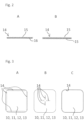
- Fig. 2A shows a principle side view of the micro suction foil 14 having one side provided with a micro suction surface 15 and another side provided with a sticky surface 16.
- the sticky surface 16 is formed by applying a bonding agent on one side of the micro suction foil 14.
- the micro suction foils 14 are respectively attached to the pads 10, 11, 12, 13 by means of the sticky surfaces 16.
- the micro suction foils 14 are attached to the upper faces of the table panels 6, 7, 8, 9 by means of the sticky surfaces 16.
- Fig. 2B shows a principle side view of the micro suction foil 14 having both sides provided with the micro suction surface 15.
- an alternative embodiment of the operating table 1 is provided with the micro suction foils 14 having both sides provided with the micro suction surface 15.
- the upper faces of the table panels 6, 7, 8, 9 contacting the micro suction foils 14 have surface structures reducing a holding force between the upper faces of the table panels 6, 7, 8, 9 and the micro suction foils 14. Therefore, the holding force between the pads 10, 11, 12, 13 and the micro suction foils 14 is larger than between the upper faces of the table panels 6, 7, 8, 9 and the micro suction foils 14.
- the micro suction foil 14 has both sides provided with the micro suction surface 15, and the faces of the pads 10, 11, 12, 13 contacting the micro suction foils 1 have surface structures reducing a holding force between the faces of the pads 10, 11, 12, 13 and the micro suction foils 14 such that the holding forces between the pads 10, 11, 12, 13 and the micro suction foil 14 are smaller than between the upper faces of the table panels 6, 7, 8, 9 and the micro suction foils 14.
- Fig. 3A shows a principle plan view of one of the pads 10, 11, 12, 13 provided with the micro suction foils 14 in the form of the micro suction tapes attached to the pads 10, 11, 12, 13 in edge regions thereof.
- the micro suction foils 14 are attached to the table panels 6, 7, 8, 9 at corresponding locations of the edge regions. Therefore, the micro suction foils 14 are configured to cover a portion of the upper faces of the table panels 6, 7, 8, 9 or of the faces of the pads 10, 11, 12, 13 facing the other one of the faces of the pad 10, 11, 12, 13 and the upper faces of the table panels 6, 7, 8, 9.
- Fig. 3B shows a principle plan view of one of the pads 10, 11, 12, 13 provided with the micro suction foils 14 in the form of the micro suction tapes attached to the pads 10, 11, 12, 13 in a central region thereof.
- the micro suction foils 14 are attached to the table panels 6, 7, 8, 9 at corresponding locations of the central region. Therefore, also in this case, the micro suction foils 14 are configured to cover a portion of the upper faces of the table panels 6, 7, 8, 9 or of the faces of the pads 10, 11, 12, 13 facing the other ones of the faces of the pads 10, 11, 12, 13 and the upper faces of the table panels 6, 7, 8, 9.
- Fig. 3C shows a principle plan view of one of the pads 10, 11, 12, 13, an entire face thereof is covered with the micro suction foil 14. Even though the edge of the micro suction foil 14 illustrated by a dashed line is illustrated spaced from an outer edge of the pad 10, 11, 12, 13, actually, the micro suction foil 14 at least almost covers the entire face of the pad 10, 11, 12, 13. Alternatively, the micro suction foils 14 are attached to the table panels 6, 7, 8, 9 in a corresponding size. Therefore, the micro suction foil 14 is configured to cover an entire upper face of the table panels 6, 7, 8, 9 or of a face of the pads 10, 11, 12, 13 facing the other one of the face of the pads 10, 11, 12, 13 and the upper face of the table panels 6, 7, 8, 9.
- Fig. 4A shows a principle side view of a portion of the operating table 1 having a labyrinth seal 17 as a liquid barrier to prevent ingress of a liquid between the micro suction foil 14 and an upper face of the table panels 6, 7, 8, 9 contacting the micro suction foil 14 or a face of the pads 10, 11, 12, 13 contacting the micro suction foil 14.
- the labyrinth seal 17 functions by elongation of a flowpath through a gap to be sealed.
- Fig. 4B shows a principle side view of a portion of the operating table 1 having a sealing lip 18 on the pad 10, 11, 12, 13 as the liquid barrier to prevent ingress of a liquid between the micro suction foil 14 and an upper face of the table panels 6, 7, 8, 9 contacting the micro suction foil 14 or a face of the pads 10, 11, 12, 13 contacting the micro suction foil 14.
- the sealing lip is provided on the upper face of the table panels 6, 7, 8, 9.
- Fig. 4C shows a principle side view of a portion of the operating table having a slit 21 as the liquid barrier.
- the liquid barrier is formed as slits 21 through the table panel 6, 7, 8, 9 in predetermined distances from edges 20 of the table panel 6, 7, 8, 9.
- the predetermined distances are defined such that the slits 21 are located between the edges 20 of the table panel 6, 7, 8, 9 and the micro suction foil 14 attached to the table panel 6, 7, 8, 9.
- liquid barriers as, e.g. caulking strips, are provided for preventing ingress of a liquid between the micro suction foil 14 and an upper face of the table panels 6, 7, 8, 9 contacting the micro suction foil 14 or a face of the pads 10, 11, 12, 13 contacting the micro suction foil 14.
- Fig. 4A, 4B and 4C show a further micro suction foil 19 configured to be sandwiched between the micro suction foil 14 and the upper face of the table panel 6, 7, 8, 9 to attach the pad 10, 11, 12, 13 to the upper face of the table panel 6, 7, 8, 9.
- the further micro suction foil 19 at least partially overlaps the micro suction foil 14.
- the further micro suction foil 19 is sandwiched between the micro suction foil 14 and the pad 10, 11, 12, 13.
Landscapes
- Health & Medical Sciences (AREA)
- Engineering & Computer Science (AREA)
- Biomedical Technology (AREA)
- Life Sciences & Earth Sciences (AREA)
- Animal Behavior & Ethology (AREA)
- General Health & Medical Sciences (AREA)
- Public Health (AREA)
- Veterinary Medicine (AREA)
- Accommodation For Nursing Or Treatment Tables (AREA)
- Handling Of Sheets (AREA)
Description
- The invention relates to an operating table, in particular, to an operating table having detachable pads on a table panel.
- Hitherto, hook and loop fasteners, i.e., so-called Velcro® fasteners, have been widely used for fixing detachable pads on a table panel of an operating table since such a fixing is quite reliable and, furthermore, it can be unfixed.
- However, these hook and loop fasteners include the disadvantage that they are difficult to clean and, therefore, a hygiene issue exists since germs and bacteria can be included in these fasteners. Other solutions to replace the hook and loop fasteners are mushroom shaped fixation knobs or sticky tapes. However, in case of the mushroom shaped fixation knobs, there is a risk of pressure ulcer and the sticky tapes collect dirt and, therefore, there is also a hygiene issue. As another solution, so-called anti-slip pads have been used, however, these pads do not actually fix the pads of the surgical table but only slightly increase the friction between the pads and the table panel.
- Document
CN 20618210 U discloses an EVA fixed body type non-slip mat for clinical semi recumbent treatment. On one side, the non-slip mat comprises a plurality of suction cups. - In document
US 2008/0113150 A1 , a suction tape comprising a large number of miniature vacuum suction cups on one side or both sides is disclosed. - Therefore, the object underlying the invention is to provide an operating table having a fixing device to fix a pad on a table panel of the operating table which eliminates the above-mentioned disadvantages and which forms a reliable fixing which is easy to handle and does not create hygiene issues.
- The object is achieved by an operating table according to
claim 1. Advantageous further developments are subject-matters of the dependent claims. - According to an aspect of the invention, an operating table comprises a table panel, a pad covering at least a portion of an upper face of the table panel, and a micro suction foil configured to be sandwiched between the upper face of the table panel and the pad to attach the pad to the upper face of the table panel.
- The micro suction foil has micro suction surfaces functioning as a huge quantity of suction cups which do not have a sticky characteristic. The micro suction foil is easy to clean and to disinfect and, when provided with an area which is large enough, it provides a sufficient holding force between the table panel and the pad. Therefore, the above-mentioned disadvantages are eliminated and a reliable fastening device is provided.
- In an advantageous implementation of the operating table, the micro suction foil has both sides provided with the micro suction surface, and the upper face of the table panel contacting the micro suction foil has a surface structure configured to reduce a holding force between the upper face of the table panel and the micro suction foil such that the holding force between the pad and the micro suction foil is larger than between the upper face of the table panel and the micro suction foil.
- By these characteristics, the micro suction foil can be attached to and removed from the table panel and the pad and, therefore, intensive cleaning and disinfecting of the pad and of the table panel is possible, wherein, afterwards, the micro suction foil can be used again. In order to define the assignment of the micro suction foil to the pad, the holding forces are adjusted such that, when removing the pad from the table panel, the micro suction foil rests on the pad so that the pad can also be used for another table panel without any fixing means.
- In another advantageous implementation of the operating table, the micro suction foil has both sides provided with a micro suction surface, and a face of the pad contacting the micro suction foil has a surface structure configured to reduce a holding force between the face of the pad and the micro suction foil such that the holding force between the pad and the micro suction foil is smaller than between the upper face of the table panel and the micro suction foil.
- By these characteristics, the micro suction foil can be attached to and removed from the table panel and the pad and, therefore, intensive cleaning and disinfecting of the pad and of the table panel is possible, wherein, afterwards, the micro suction foil can be used again. In order to define the assignment of the micro suction foil to the table panel, the holding forces are adjusted such that the micro suction foil rests on the table panel so that another pad without any fixing means can also be used with the operating table.
- In a further advantageous implementation of the operating table, the micro suction foil comprises a side provided with a sticky surface and another side provided with a micro suction surface, and the micro suction foil is attached to the pad by means of the sticky surface.
- Due to this fixing by the sticky surface, the micro suction foil is fixedly assigned to the pad so that the pad is always provided with the fixing means and a pad can be attached independently from a presence of a fixing means on the table panel.
- In another advantageous implementation of the operating table, the micro suction foil comprises of a sticky surface on one side and a micro suction surface on the other. The micro suction foil is attached to the upper face of the table panel by means of the sticky surface.
- Due to this fixing by the sticky surface, the micro suction foil is fixedly assigned to the table panel so that the table panel is always provided with the fixing means and a pad can be attached independently from a presence of a fixing means on the pad.
- In a further advantageous implementation of the operating table, the micro suction foil is configured to cover an entire upper face of the table panel and the face of the pad facing each other which is larger than the other one.
- When covering the larger one of the entire face, an attachment area is as large as possible so that a holding force is large. Nevertheless, the pad can easily be removed when bending the pad so that the fixing is unfixed in a rolling line contact.
- In a further advantageous implementation of the operating table, the micro suction foil is configured to cover a portion of the upper face of the table panel or of a face of the pad facing the other one of the face of the pad and the upper face of the table panel.
- By this configuration, the amount of the micro suction foil can be saved so that the minimum required holding force is ensured and costs and mounting efforts are reduced.
- In a further advantageous implementation of the operating table, the micro suction foil is configured as a micro suction tape, and the micro suction tape is attached to the pad or to the upper face of the table panel in an edge region thereof.
- By the attachment in an edge region of the pad or the table panel, except from saving the amount of the micro suction foil, a safe fixing and orientation of the pad with respect to the table panel is ensured.
- In a further advantageous implementation of the operating table, the micro suction foil is configured as a micro suction tape, and the micro suction tape is attached to the pad or to the upper face of the table panel in an central region thereof.
- Due to the fixing in the central area of the pad or of the table panel, except from saving the amount of the micro suction foil, the pad can easily be deformed when loaded by a patient so that a flexibility of the pad is enhanced.
- In a further advantageous implementation of the operating table, a further micro suction foil configured to be sandwiched between the micro suction foil and the upper face of the table panel or the pad is provided to attach the pad to the upper face of the table panel. The further micro suction foil at least partially overlaps the micro suction foil.
- By the provision of the further micro suction foil at least partially overlapping the micro suction foil, the holding force is increased.
- In a further advantageous implementation of the operating table, the operating table further comprises a liquid barrier configured to prevent ingress of a liquid between the micro suction foil and an upper face of the table panel contacting the micro suction foil or a face of the pad contacting the micro suction foil.
- A characteristic of the micro suction foil is that it loses holding force when being wet also in a case when the pad is already attached to the table panel due to a capillary effect. Therefore providing the liquid barrier prevents the loss of the holding force.
- In a further advantageous implementation of the operating table, the liquid barrier is formed as a labyrinth seal.
- A labyrinth seal, e.g., in the form of a downwardly projecting edge of the pad adjacent to an edge of the table panel, is an easy measure for providing a liquid tightness.
- In a further advantageous implementation of the operating table, the liquid barrier is formed as a sealing lip.
- A sealing lip, e.g., in the form of a downwardly projecting edge of the pad contacting the upper face of the table panel, is an easy measure for providing a liquid tightness.
- In a further advantageous implementation of the operating table, the liquid barrier is formed as slits through the table panel in predetermined distances from edges of the table panel, the predetermined distances being defined such that the slits are located between the edges of the table panel and the micro suction foil attached to the table panel.
- By the slits, liquid intruded between the table panel and the pad can be drained so that it does not reach the micro suction foil in order to prevent loss of the holding force.
- Below, the invention is elucidated by means of embodiments referring to the attached drawings.
- In particular,
- Fig. 1
- shows an operating table according to an embodiment of the invention;
- Fig. 2A
- shows a principle side view of an embodiment of a micro suction foil having one side provided with a sticky surface and another side provided with a micro suction surface;
- Fig. 2B
- shows a principle side view of another embodiment of the micro suction foil having both sides provided with a micro suction surface;
- Fig. 3A
- shows a principle plan view of a pad of the operating table provided with micro suction foils in edge regions thereof;
- Fig. 3B
- shows a principle plan view of the pad of the operating table provided with micro suction foils in a central region thereof;
- Fig. 3C
- shows a principle plan view of the pad of the operating table, an entire face thereof is covered with a micro suction foil;
- Fig. 4A
- shows a principle side view of a portion of the operating table having a labyrinth seal as a liquid barrier;
- Fig. 4B
- shows a principle side view of a portion of the operating table having a sealing lip as the liquid barrier, and
- Fig. 4C
- shows a principle side view of a portion of the operating table having a slit as the liquid barrier.
-
Fig. 1 shows an operating table 1 according to an embodiment of the invention. The operating table 1 comprisesseveral sections sections table panel pad pads pad table panels - The operating table 1 further comprises micro suction foils 14 in the form of micro suction tapes. The micro suction foils 14 are formed, at least on one side, by, e.g. microscopic craters in its surface functioning like micro suction cups. Therefore, they stick to smooth surfaces without any bonding agent. The micro suction foils 14 attach the
pads table panels Fig. 1 , each of thepads respective table panel -
Fig. 2A shows a principle side view of themicro suction foil 14 having one side provided with amicro suction surface 15 and another side provided with asticky surface 16. Thesticky surface 16 is formed by applying a bonding agent on one side of themicro suction foil 14. Back toFig. 1 , the micro suction foils 14 are respectively attached to thepads table panels -
Fig. 2B shows a principle side view of themicro suction foil 14 having both sides provided with themicro suction surface 15. Back toFig. 1 , an alternative embodiment of the operating table 1 is provided with the micro suction foils 14 having both sides provided with themicro suction surface 15. The upper faces of thetable panels table panels pads table panels - In a further alternative embodiment of the operating table 1, the
micro suction foil 14 has both sides provided with themicro suction surface 15, and the faces of thepads pads pads micro suction foil 14 are smaller than between the upper faces of thetable panels -
Fig. 3A shows a principle plan view of one of thepads pads table panels table panels pads pad table panels -
Fig. 3B shows a principle plan view of one of thepads pads table panels table panels pads pads table panels -
Fig. 3C shows a principle plan view of one of thepads micro suction foil 14. Even though the edge of themicro suction foil 14 illustrated by a dashed line is illustrated spaced from an outer edge of thepad micro suction foil 14 at least almost covers the entire face of thepad table panels micro suction foil 14 is configured to cover an entire upper face of thetable panels pads pads table panels -
Fig. 4A shows a principle side view of a portion of the operating table 1 having alabyrinth seal 17 as a liquid barrier to prevent ingress of a liquid between themicro suction foil 14 and an upper face of thetable panels micro suction foil 14 or a face of thepads micro suction foil 14. Thelabyrinth seal 17 functions by elongation of a flowpath through a gap to be sealed. -
Fig. 4B shows a principle side view of a portion of the operating table 1 having a sealinglip 18 on thepad micro suction foil 14 and an upper face of thetable panels micro suction foil 14 or a face of thepads micro suction foil 14. Alternatively, the sealing lip is provided on the upper face of thetable panels -
Fig. 4C shows a principle side view of a portion of the operating table having aslit 21 as the liquid barrier. - The liquid barrier is formed as
slits 21 through thetable panel edges 20 of thetable panel slits 21 are located between theedges 20 of thetable panel micro suction foil 14 attached to thetable panel - In further alternative embodiments, other liquid barriers, as, e.g. caulking strips, are provided for preventing ingress of a liquid between the
micro suction foil 14 and an upper face of thetable panels micro suction foil 14 or a face of thepads micro suction foil 14. - Moreover,
Fig. 4A, 4B and 4C show a furthermicro suction foil 19 configured to be sandwiched between themicro suction foil 14 and the upper face of thetable panel pad table panel micro suction foil 19 at least partially overlaps themicro suction foil 14. In an alternative embodiment, the furthermicro suction foil 19 is sandwiched between themicro suction foil 14 and thepad - While the invention has been illustrated and described in detail in the drawings and the foregoing description, such illustration and description are to be considered illustrative or exemplary and not restrictive. The invention is not limited to the disclosed embodiments. From reading the present disclosure, other modifications will be apparent to a person skilled in the art. Such modifications may involve other features, which are already known in the art and may be used instead of or in addition to features already described herein. In the claims, the word "comprising" does not exclude other elements or steps, and the indefinite article "a" or "an" does not exclude a plurality.
Claims (12)
- An operating table (1) comprising:a table panel (6, 7, 8, 9),a pad (10, 11, 12, 13) covering at least a portion of an upper face of the table panel (6, 7, 8, 9), anda first micro suction foil (14) configured to be sandwiched between the upper face of the table panel (6, 7, 8, 9) and the pad (10, 11, 12, 13) to attach the pad (10, 11, 12, 13) to the upper face of the table panel (6, 7, 8, 9),characterized in thatthe operating table (1) comprises a further micro suction foil (19) configured to be sandwiched between the first micro suction foil (14) and the upper face of the table panel (6, 7, 8, 9) or the pad (10, 11, 12, 13) to attach the pad (10, 11, 12, 13) to the upper face of the table panel (6, 7, 8, 9), the further micro suction foil (19) at least partially overlapping the first micro suction foil (14).
- The operating table (1) of claim 1, wherein
the first micro suction foil (14) has both sides provided with a micro suction surface (15), and the upper face of the table panel (6, 7, 8, 9) contacting the first micro suction foil (14) has a surface structure configured to reduce a holding force between the upper face of the table panel (6, 7, 8, 9) and the first micro suction foil (14) such that the holding force between the pad (10, 11, 12, 13) and the first micro suction foil (14) is larger than between the upper face of the table panel (6, 7, 8, 9) and the first micro suction foil (14). - The operating table (1) of claim 1, wherein
the first micro suction foil (14) has both sides provided with a micro suction surface (15), and a face of the pad (10, 11, 12, 13) contacting the first micro suction foil (14) has a surface structure configured to reduce a holding force between the face of the pad (10, 11, 12, 13) and the first micro suction foil (14) such that the holding force between the pad (10, 11, 12, 13) and the first micro suction foil (14) is smaller than between the upper face of the table panel (6, 7, 8, 9) and the first micro suction foil (14). - The operating table (1) of claim 1, whereinthe first micro suction foil (14) comprises a side provided with a sticky surface (16) and another side provided with a micro suction surface (15), andthe first micro suction foil (14) is attached to the pad (10, 11, 12, 13) by means of the sticky surface (16).
- The operating table (1) of claim 1, whereinthe first micro suction foil (14) comprises one side provided with a sticky surface (16) and another side provided with a micro suction surface (15), andthe first micro suction foil (14) is attached to the upper face of the table panel (6, 7, 8, 9) by means of the sticky surface (16).
- The operating table (1) of anyone of claim 1 to 4, wherein
the first micro suction foil (14) is configured to cover a portion of the upper face of the table panel (6, 7, 8, 9) or of a face of the pad (10, 11, 12, 13) facing the other one of the face of the pad (10, 11, 12, 13) and the upper face of the table panel (6, 7, 8, 9). - The operating table (1) of claim 6, wherein
the first micro suction foil (14) is configured as a micro suction tape, and the micro suction tape is attached to the pad (10, 11, 12, 13) or to the upper face of the table panel (6, 7, 8, 9) in an edge region thereof. - The operating table (1) of claim 6, wherein
the first micro suction foil (14) is configured as a micro suction tape, and the micro suction tape is attached to the pad (10, 11, 12, 13) or to the upper face of the table panel (6, 7, 8, 9) in a central region thereof. - The operating table (1) of any preceding claim, wherein
the operating table (1) further comprises a liquid barrier configured to prevent ingress of a liquid between the first micro suction foil (14) and an upper face of the table panel (6, 7, 8, 9) contacting the first micro suction foil (14) or a face of the pad (10, 11, 12, 13) contacting the first micro suction foil (14). - The operating table (1) of claim 9, wherein the liquid barrier is formed as a labyrinth seal (17).
- The operating table (1) of claim 9, wherein the liquid barrier is formed as a sealing lip (18).
- The operating table (1) of claim 9, wherein the liquid barrier is formed as slits (21) through the table panel (6, 7, 8, 9) in predetermined distances from edges (20) of the table panel (6, 7, 8, 9), the predetermined distances being defined such that the slits (21) are located between the edges (20) and the first micro suction foil (14) attached to the table panel (6, 7, 8, 9).
Priority Applications (3)
| Application Number | Priority Date | Filing Date | Title |
|---|---|---|---|
| EP19152616.9A EP3682861B1 (en) | 2019-01-18 | 2019-01-18 | Operating table |
| CN201922149258.9U CN212308333U (en) | 2019-01-18 | 2019-12-04 | Operating table |
| US16/745,677 US20200230010A1 (en) | 2019-01-18 | 2020-01-17 | Operating table |
Applications Claiming Priority (1)
| Application Number | Priority Date | Filing Date | Title |
|---|---|---|---|
| EP19152616.9A EP3682861B1 (en) | 2019-01-18 | 2019-01-18 | Operating table |
Publications (2)
| Publication Number | Publication Date |
|---|---|
| EP3682861A1 EP3682861A1 (en) | 2020-07-22 |
| EP3682861B1 true EP3682861B1 (en) | 2023-08-30 |
Family
ID=65199306
Family Applications (1)
| Application Number | Title | Priority Date | Filing Date |
|---|---|---|---|
| EP19152616.9A Active EP3682861B1 (en) | 2019-01-18 | 2019-01-18 | Operating table |
Country Status (3)
| Country | Link |
|---|---|
| US (1) | US20200230010A1 (en) |
| EP (1) | EP3682861B1 (en) |
| CN (1) | CN212308333U (en) |
Families Citing this family (1)
| Publication number | Priority date | Publication date | Assignee | Title |
|---|---|---|---|---|
| CN113197747A (en) * | 2021-04-06 | 2021-08-03 | 李修龙 | Spinal surgery bracket device for neurosurgery |
Family Cites Families (2)
| Publication number | Priority date | Publication date | Assignee | Title |
|---|---|---|---|---|
| US20080113150A1 (en) * | 2006-11-13 | 2008-05-15 | Calvin Chunliang Lee | Suction tape |
| CN206198210U (en) * | 2016-06-24 | 2017-05-31 | 洪爱治 | EVA fixation postures formula slipmat |
-
2019
- 2019-01-18 EP EP19152616.9A patent/EP3682861B1/en active Active
- 2019-12-04 CN CN201922149258.9U patent/CN212308333U/en active Active
-
2020
- 2020-01-17 US US16/745,677 patent/US20200230010A1/en not_active Abandoned
Also Published As
| Publication number | Publication date |
|---|---|
| EP3682861A1 (en) | 2020-07-22 |
| CN212308333U (en) | 2021-01-08 |
| US20200230010A1 (en) | 2020-07-23 |
Similar Documents
| Publication | Publication Date | Title |
|---|---|---|
| US4644592A (en) | Disposable floor mat | |
| EP0447217B1 (en) | Surgical drape having 360 degree fluid control | |
| US20090312685A1 (en) | Adhesive Wafer | |
| WO2020028050A1 (en) | Tri-layered wound dressing and method therefor | |
| CA1124154A (en) | Ostomy appliance | |
| US6874505B1 (en) | Surgical drape system with pouch | |
| CZ20033048A3 (en) | Self-adhesive band with improved adhesive properties for sealing gaps in building construction | |
| US6824853B1 (en) | Pliable pad for collecting and absorbing liquids | |
| EP3682861A1 (en) | Operating table | |
| WO2005053754A2 (en) | Covering for an aseptic treatment site | |
| EP1008330A3 (en) | Adhesive bandage | |
| US4386932A (en) | Absorbent article | |
| KR20050113208A (en) | Device for the analgesic immobilisation of broken ribs | |
| US20050043648A1 (en) | Epicutaneous test plaster | |
| CN214858141U (en) | Cold plaster | |
| CA2473710C (en) | Cofferdam covering means and strip-shaped fastening means for the same | |
| JPH0541527U (en) | Sanitary napkin | |
| JP4079562B2 (en) | Sheet glass holding member | |
| SE524357C2 (en) | dressing support | |
| RU210469U1 (en) | Device for fixing a removable dirt-protective floor covering | |
| CN223682319U (en) | Wire protection ground mat | |
| JP3046954U (en) | Gibbs guard | |
| RU2312197C2 (en) | Device for threshold connection to floor | |
| KR860000129Y1 (en) | Device for massage tape with sulface bump | |
| CN112998937A (en) | Cold plaster |
Legal Events
| Date | Code | Title | Description |
|---|---|---|---|
| PUAI | Public reference made under article 153(3) epc to a published international application that has entered the european phase |
Free format text: ORIGINAL CODE: 0009012 |
|
| STAA | Information on the status of an ep patent application or granted ep patent |
Free format text: STATUS: THE APPLICATION HAS BEEN PUBLISHED |
|
| AK | Designated contracting states |
Kind code of ref document: A1 Designated state(s): AL AT BE BG CH CY CZ DE DK EE ES FI FR GB GR HR HU IE IS IT LI LT LU LV MC MK MT NL NO PL PT RO RS SE SI SK SM TR |
|
| AX | Request for extension of the european patent |
Extension state: BA ME |
|
| STAA | Information on the status of an ep patent application or granted ep patent |
Free format text: STATUS: REQUEST FOR EXAMINATION WAS MADE |
|
| 17P | Request for examination filed |
Effective date: 20210119 |
|
| RBV | Designated contracting states (corrected) |
Designated state(s): AL AT BE BG CH CY CZ DE DK EE ES FI FR GB GR HR HU IE IS IT LI LT LU LV MC MK MT NL NO PL PT RO RS SE SI SK SM TR |
|
| GRAP | Despatch of communication of intention to grant a patent |
Free format text: ORIGINAL CODE: EPIDOSNIGR1 |
|
| STAA | Information on the status of an ep patent application or granted ep patent |
Free format text: STATUS: GRANT OF PATENT IS INTENDED |
|
| RIC1 | Information provided on ipc code assigned before grant |
Ipc: A61G 13/12 20060101AFI20221116BHEP |
|
| INTG | Intention to grant announced |
Effective date: 20221202 |
|
| GRAJ | Information related to disapproval of communication of intention to grant by the applicant or resumption of examination proceedings by the epo deleted |
Free format text: ORIGINAL CODE: EPIDOSDIGR1 |
|
| STAA | Information on the status of an ep patent application or granted ep patent |
Free format text: STATUS: REQUEST FOR EXAMINATION WAS MADE |
|
| GRAP | Despatch of communication of intention to grant a patent |
Free format text: ORIGINAL CODE: EPIDOSNIGR1 |
|
| STAA | Information on the status of an ep patent application or granted ep patent |
Free format text: STATUS: GRANT OF PATENT IS INTENDED |
|
| INTC | Intention to grant announced (deleted) | ||
| RAP3 | Party data changed (applicant data changed or rights of an application transferred) |
Owner name: BAXTER MEDICAL SYSTEMS GMBH + CO. KG |
|
| INTG | Intention to grant announced |
Effective date: 20230405 |
|
| GRAS | Grant fee paid |
Free format text: ORIGINAL CODE: EPIDOSNIGR3 |
|
| GRAA | (expected) grant |
Free format text: ORIGINAL CODE: 0009210 |
|
| STAA | Information on the status of an ep patent application or granted ep patent |
Free format text: STATUS: THE PATENT HAS BEEN GRANTED |
|
| AK | Designated contracting states |
Kind code of ref document: B1 Designated state(s): AL AT BE BG CH CY CZ DE DK EE ES FI FR GB GR HR HU IE IS IT LI LT LU LV MC MK MT NL NO PL PT RO RS SE SI SK SM TR |
|
| REG | Reference to a national code |
Ref country code: GB Ref legal event code: FG4D |
|
| REG | Reference to a national code |
Ref country code: CH Ref legal event code: EP |
|
| REG | Reference to a national code |
Ref country code: DE Ref legal event code: R096 Ref document number: 602019035915 Country of ref document: DE |
|
| REG | Reference to a national code |
Ref country code: IE Ref legal event code: FG4D |
|
| REG | Reference to a national code |
Ref country code: LT Ref legal event code: MG9D |
|
| REG | Reference to a national code |
Ref country code: NL Ref legal event code: MP Effective date: 20230830 |
|
| REG | Reference to a national code |
Ref country code: AT Ref legal event code: MK05 Ref document number: 1604481 Country of ref document: AT Kind code of ref document: T Effective date: 20230830 |
|
| PG25 | Lapsed in a contracting state [announced via postgrant information from national office to epo] |
Ref country code: GR Free format text: LAPSE BECAUSE OF FAILURE TO SUBMIT A TRANSLATION OF THE DESCRIPTION OR TO PAY THE FEE WITHIN THE PRESCRIBED TIME-LIMIT Effective date: 20231201 |
|
| PG25 | Lapsed in a contracting state [announced via postgrant information from national office to epo] |
Ref country code: IS Free format text: LAPSE BECAUSE OF FAILURE TO SUBMIT A TRANSLATION OF THE DESCRIPTION OR TO PAY THE FEE WITHIN THE PRESCRIBED TIME-LIMIT Effective date: 20231230 |
|
| PG25 | Lapsed in a contracting state [announced via postgrant information from national office to epo] |
Ref country code: SE Free format text: LAPSE BECAUSE OF FAILURE TO SUBMIT A TRANSLATION OF THE DESCRIPTION OR TO PAY THE FEE WITHIN THE PRESCRIBED TIME-LIMIT Effective date: 20230830 Ref country code: RS Free format text: LAPSE BECAUSE OF FAILURE TO SUBMIT A TRANSLATION OF THE DESCRIPTION OR TO PAY THE FEE WITHIN THE PRESCRIBED TIME-LIMIT Effective date: 20230830 Ref country code: NO Free format text: LAPSE BECAUSE OF FAILURE TO SUBMIT A TRANSLATION OF THE DESCRIPTION OR TO PAY THE FEE WITHIN THE PRESCRIBED TIME-LIMIT Effective date: 20231130 Ref country code: LV Free format text: LAPSE BECAUSE OF FAILURE TO SUBMIT A TRANSLATION OF THE DESCRIPTION OR TO PAY THE FEE WITHIN THE PRESCRIBED TIME-LIMIT Effective date: 20230830 Ref country code: LT Free format text: LAPSE BECAUSE OF FAILURE TO SUBMIT A TRANSLATION OF THE DESCRIPTION OR TO PAY THE FEE WITHIN THE PRESCRIBED TIME-LIMIT Effective date: 20230830 Ref country code: IS Free format text: LAPSE BECAUSE OF FAILURE TO SUBMIT A TRANSLATION OF THE DESCRIPTION OR TO PAY THE FEE WITHIN THE PRESCRIBED TIME-LIMIT Effective date: 20231230 Ref country code: HR Free format text: LAPSE BECAUSE OF FAILURE TO SUBMIT A TRANSLATION OF THE DESCRIPTION OR TO PAY THE FEE WITHIN THE PRESCRIBED TIME-LIMIT Effective date: 20230830 Ref country code: GR Free format text: LAPSE BECAUSE OF FAILURE TO SUBMIT A TRANSLATION OF THE DESCRIPTION OR TO PAY THE FEE WITHIN THE PRESCRIBED TIME-LIMIT Effective date: 20231201 Ref country code: FI Free format text: LAPSE BECAUSE OF FAILURE TO SUBMIT A TRANSLATION OF THE DESCRIPTION OR TO PAY THE FEE WITHIN THE PRESCRIBED TIME-LIMIT Effective date: 20230830 Ref country code: AT Free format text: LAPSE BECAUSE OF FAILURE TO SUBMIT A TRANSLATION OF THE DESCRIPTION OR TO PAY THE FEE WITHIN THE PRESCRIBED TIME-LIMIT Effective date: 20230830 |
|
| PG25 | Lapsed in a contracting state [announced via postgrant information from national office to epo] |
Ref country code: PL Free format text: LAPSE BECAUSE OF FAILURE TO SUBMIT A TRANSLATION OF THE DESCRIPTION OR TO PAY THE FEE WITHIN THE PRESCRIBED TIME-LIMIT Effective date: 20230830 Ref country code: NL Free format text: LAPSE BECAUSE OF FAILURE TO SUBMIT A TRANSLATION OF THE DESCRIPTION OR TO PAY THE FEE WITHIN THE PRESCRIBED TIME-LIMIT Effective date: 20230830 |
|
| PG25 | Lapsed in a contracting state [announced via postgrant information from national office to epo] |
Ref country code: ES Free format text: LAPSE BECAUSE OF FAILURE TO SUBMIT A TRANSLATION OF THE DESCRIPTION OR TO PAY THE FEE WITHIN THE PRESCRIBED TIME-LIMIT Effective date: 20230830 |
|
| PG25 | Lapsed in a contracting state [announced via postgrant information from national office to epo] |
Ref country code: SM Free format text: LAPSE BECAUSE OF FAILURE TO SUBMIT A TRANSLATION OF THE DESCRIPTION OR TO PAY THE FEE WITHIN THE PRESCRIBED TIME-LIMIT Effective date: 20230830 Ref country code: RO Free format text: LAPSE BECAUSE OF FAILURE TO SUBMIT A TRANSLATION OF THE DESCRIPTION OR TO PAY THE FEE WITHIN THE PRESCRIBED TIME-LIMIT Effective date: 20230830 Ref country code: ES Free format text: LAPSE BECAUSE OF FAILURE TO SUBMIT A TRANSLATION OF THE DESCRIPTION OR TO PAY THE FEE WITHIN THE PRESCRIBED TIME-LIMIT Effective date: 20230830 Ref country code: EE Free format text: LAPSE BECAUSE OF FAILURE TO SUBMIT A TRANSLATION OF THE DESCRIPTION OR TO PAY THE FEE WITHIN THE PRESCRIBED TIME-LIMIT Effective date: 20230830 Ref country code: DK Free format text: LAPSE BECAUSE OF FAILURE TO SUBMIT A TRANSLATION OF THE DESCRIPTION OR TO PAY THE FEE WITHIN THE PRESCRIBED TIME-LIMIT Effective date: 20230830 Ref country code: CZ Free format text: LAPSE BECAUSE OF FAILURE TO SUBMIT A TRANSLATION OF THE DESCRIPTION OR TO PAY THE FEE WITHIN THE PRESCRIBED TIME-LIMIT Effective date: 20230830 Ref country code: SK Free format text: LAPSE BECAUSE OF FAILURE TO SUBMIT A TRANSLATION OF THE DESCRIPTION OR TO PAY THE FEE WITHIN THE PRESCRIBED TIME-LIMIT Effective date: 20230830 Ref country code: PT Free format text: LAPSE BECAUSE OF FAILURE TO SUBMIT A TRANSLATION OF THE DESCRIPTION OR TO PAY THE FEE WITHIN THE PRESCRIBED TIME-LIMIT Effective date: 20240102 |
|
| PG25 | Lapsed in a contracting state [announced via postgrant information from national office to epo] |
Ref country code: IT Free format text: LAPSE BECAUSE OF FAILURE TO SUBMIT A TRANSLATION OF THE DESCRIPTION OR TO PAY THE FEE WITHIN THE PRESCRIBED TIME-LIMIT Effective date: 20230830 |
|
| REG | Reference to a national code |
Ref country code: DE Ref legal event code: R097 Ref document number: 602019035915 Country of ref document: DE |
|
| PLBE | No opposition filed within time limit |
Free format text: ORIGINAL CODE: 0009261 |
|
| STAA | Information on the status of an ep patent application or granted ep patent |
Free format text: STATUS: NO OPPOSITION FILED WITHIN TIME LIMIT |
|
| PG25 | Lapsed in a contracting state [announced via postgrant information from national office to epo] |
Ref country code: SI Free format text: LAPSE BECAUSE OF FAILURE TO SUBMIT A TRANSLATION OF THE DESCRIPTION OR TO PAY THE FEE WITHIN THE PRESCRIBED TIME-LIMIT Effective date: 20230830 |
|
| 26N | No opposition filed |
Effective date: 20240603 |
|
| PG25 | Lapsed in a contracting state [announced via postgrant information from national office to epo] |
Ref country code: MC Free format text: LAPSE BECAUSE OF FAILURE TO SUBMIT A TRANSLATION OF THE DESCRIPTION OR TO PAY THE FEE WITHIN THE PRESCRIBED TIME-LIMIT Effective date: 20230830 |
|
| PG25 | Lapsed in a contracting state [announced via postgrant information from national office to epo] |
Ref country code: MC Free format text: LAPSE BECAUSE OF FAILURE TO SUBMIT A TRANSLATION OF THE DESCRIPTION OR TO PAY THE FEE WITHIN THE PRESCRIBED TIME-LIMIT Effective date: 20230830 |
|
| REG | Reference to a national code |
Ref country code: CH Ref legal event code: PL |
|
| PG25 | Lapsed in a contracting state [announced via postgrant information from national office to epo] |
Ref country code: LU Free format text: LAPSE BECAUSE OF NON-PAYMENT OF DUE FEES Effective date: 20240118 |
|
| PG25 | Lapsed in a contracting state [announced via postgrant information from national office to epo] |
Ref country code: LU Free format text: LAPSE BECAUSE OF NON-PAYMENT OF DUE FEES Effective date: 20240118 |
|
| PG25 | Lapsed in a contracting state [announced via postgrant information from national office to epo] |
Ref country code: BE Free format text: LAPSE BECAUSE OF NON-PAYMENT OF DUE FEES Effective date: 20240131 |
|
| PG25 | Lapsed in a contracting state [announced via postgrant information from national office to epo] |
Ref country code: CH Free format text: LAPSE BECAUSE OF NON-PAYMENT OF DUE FEES Effective date: 20240131 |
|
| PG25 | Lapsed in a contracting state [announced via postgrant information from national office to epo] |
Ref country code: CH Free format text: LAPSE BECAUSE OF NON-PAYMENT OF DUE FEES Effective date: 20240131 Ref country code: BE Free format text: LAPSE BECAUSE OF NON-PAYMENT OF DUE FEES Effective date: 20240131 |
|
| REG | Reference to a national code |
Ref country code: BE Ref legal event code: MM Effective date: 20240131 |
|
| PG25 | Lapsed in a contracting state [announced via postgrant information from national office to epo] |
Ref country code: BG Free format text: LAPSE BECAUSE OF FAILURE TO SUBMIT A TRANSLATION OF THE DESCRIPTION OR TO PAY THE FEE WITHIN THE PRESCRIBED TIME-LIMIT Effective date: 20230830 |
|
| PG25 | Lapsed in a contracting state [announced via postgrant information from national office to epo] |
Ref country code: BG Free format text: LAPSE BECAUSE OF FAILURE TO SUBMIT A TRANSLATION OF THE DESCRIPTION OR TO PAY THE FEE WITHIN THE PRESCRIBED TIME-LIMIT Effective date: 20230830 |
|
| PG25 | Lapsed in a contracting state [announced via postgrant information from national office to epo] |
Ref country code: IE Free format text: LAPSE BECAUSE OF NON-PAYMENT OF DUE FEES Effective date: 20240118 |
|
| PG25 | Lapsed in a contracting state [announced via postgrant information from national office to epo] |
Ref country code: IE Free format text: LAPSE BECAUSE OF NON-PAYMENT OF DUE FEES Effective date: 20240118 |
|
| PG25 | Lapsed in a contracting state [announced via postgrant information from national office to epo] |
Ref country code: CY Free format text: LAPSE BECAUSE OF FAILURE TO SUBMIT A TRANSLATION OF THE DESCRIPTION OR TO PAY THE FEE WITHIN THE PRESCRIBED TIME-LIMIT; INVALID AB INITIO Effective date: 20190118 |
|
| PG25 | Lapsed in a contracting state [announced via postgrant information from national office to epo] |
Ref country code: HU Free format text: LAPSE BECAUSE OF FAILURE TO SUBMIT A TRANSLATION OF THE DESCRIPTION OR TO PAY THE FEE WITHIN THE PRESCRIBED TIME-LIMIT; INVALID AB INITIO Effective date: 20190118 |
|
| PG25 | Lapsed in a contracting state [announced via postgrant information from national office to epo] |
Ref country code: TR Free format text: LAPSE BECAUSE OF FAILURE TO SUBMIT A TRANSLATION OF THE DESCRIPTION OR TO PAY THE FEE WITHIN THE PRESCRIBED TIME-LIMIT Effective date: 20230830 |
|
| PGFP | Annual fee paid to national office [announced via postgrant information from national office to epo] |
Ref country code: GB Payment date: 20251217 Year of fee payment: 8 |
|
| PGFP | Annual fee paid to national office [announced via postgrant information from national office to epo] |
Ref country code: FR Payment date: 20251217 Year of fee payment: 8 |
|
| PGFP | Annual fee paid to national office [announced via postgrant information from national office to epo] |
Ref country code: DE Payment date: 20251217 Year of fee payment: 8 |