EP0447217B1 - Surgical drape having 360 degree fluid control - Google Patents
Surgical drape having 360 degree fluid control Download PDFInfo
- Publication number
- EP0447217B1 EP0447217B1 EP91302132A EP91302132A EP0447217B1 EP 0447217 B1 EP0447217 B1 EP 0447217B1 EP 91302132 A EP91302132 A EP 91302132A EP 91302132 A EP91302132 A EP 91302132A EP 0447217 B1 EP0447217 B1 EP 0447217B1
- Authority
- EP
- European Patent Office
- Prior art keywords
- sheet
- perimetric edge
- patient
- section
- top sheet
- Prior art date
- Legal status (The legal status is an assumption and is not a legal conclusion. Google has not performed a legal analysis and makes no representation as to the accuracy of the status listed.)
- Expired - Lifetime
Links
Images


Classifications
-
- A—HUMAN NECESSITIES
- A61—MEDICAL OR VETERINARY SCIENCE; HYGIENE
- A61M—DEVICES FOR INTRODUCING MEDIA INTO, OR ONTO, THE BODY; DEVICES FOR TRANSDUCING BODY MEDIA OR FOR TAKING MEDIA FROM THE BODY; DEVICES FOR PRODUCING OR ENDING SLEEP OR STUPOR
- A61M27/00—Drainage appliance for wounds or the like, i.e. wound drains, implanted drains
-
- A—HUMAN NECESSITIES
- A61—MEDICAL OR VETERINARY SCIENCE; HYGIENE
- A61B—DIAGNOSIS; SURGERY; IDENTIFICATION
- A61B46/00—Surgical drapes
- A61B46/30—Surgical drapes for surgery through the lower body openings, e.g. urology, gynaecology
-
- A—HUMAN NECESSITIES
- A61—MEDICAL OR VETERINARY SCIENCE; HYGIENE
- A61B—DIAGNOSIS; SURGERY; IDENTIFICATION
- A61B46/00—Surgical drapes
-
- A—HUMAN NECESSITIES
- A61—MEDICAL OR VETERINARY SCIENCE; HYGIENE
- A61B—DIAGNOSIS; SURGERY; IDENTIFICATION
- A61B46/00—Surgical drapes
- A61B46/20—Surgical drapes specially adapted for patients
- A61B2046/205—Adhesive drapes
Definitions
- the present invention relates to devices for collecting fluid from a patient and more particularly to surgical drapes having means for collecting and controlling the fluids which accumulate during surgical procedures, such as Caesarian section deliveries.
- Surgical drapes comprising a sheet of flexible material having a fenestration and a spaced apart region for collecting the fluids and materials emanating from the patient during the surgical procedure are well known.
- U.S. Patent 4,462,396--Wichman discloses a drape having a flexible pocket secured to top surface of a drape. A fitting attached to the pocket permits a tube to be utilized to drain the pocket of the fluids collected.
- U.S. Patent 4,559,937 - Vinson and U.S. Patent 4,598,458 - McAllester disclose surgical drapes having fluid collection bags spaced at a location whereby the fluid will flow by gravity and be collected and stored.
- a surgical drape for cystoscopic procedures having a fenestration and a folded pocket located in the path of the fluid runoff is disclosed in U.S. Patent 4,414,968 - Amin.
- a method of collecting postpartum fluid is disclosed in U.S. Patent 4,105,019 - Haswell. The method disclosed utilizes a sheet-like receptacle having two pockets one for collecting amniotic fluid and one for collecting blood.
- a fluid collection apron for use during transurethral resection is disclosed in U.S. Patent 4,007,741 - Waldrop, et al.
- the apron is attached to the urological operating table and to the surgeon's neck.
- the apron collects fluid and drains it through a tube into a remote collection receptacle.
- US-A-4890628 discloses a surgical drape with means for channeling and collecting fluids. Also disclosed is the use of malleable strips which are intended to hold the channeling and collecting means in the appropriate configuration.
- the apparatus disclosed by the present invention provides one or more elongated bendable means extending longitudinally substantially along the inner perimetric edge of a thin pliable sheet of liquid impervious material.
- the device comprises a first sheet of liquid impervious material having an opening.
- the first sheet is attached to a bottom sheet of liquid impervious material having a fenestration for access to the patient.
- the bendable means retain the inner perimetric edge of an opening in the top sheet in a defined shape, improving fluid collection and access.
- the bendable means are preferably formed of a metallic section embedded in a cover, such as a wire covered by a pliable plastic material.
- the bendable means are encased by providing an intermediate sheet of liquid impervious material and placing the bendable means between the first and intermediate sheets.
- the intermediate sheet may be in registration with the first sheet and secured in a liquid tight relationship at least along the inner and outer perimetric edges.
- the intermediate sheet may be comprised of an annular section of material, secured in a liquid tight relationship to the first sheet along the inner perimetric edge.
- the sheets are secured by heat sealing.
- the fenestration section is secured to the bottom sheet in a liquid tight relationship, preferably by heat sealing.
- a portion of said bottom sheet is coated with adhesive on said patient facing side and most preferably, the fenestration section is coated with adhesive.
- Certain embodiments also comprise drainage ports for transmitting fluids which are affixed to the bottom side.
- the present invention also provides a surgical drape for overlying a patient comprising a sheet of drape material having at least one opening for access to the patient and having a device for collecting fluids as described above attached thereto.
- Drapes disclosed also comprise a pad of absorbent material overlying said drape material and means for retaining a drainage tube. Methods of manufacturing a fluid collecting device are also disclosed.
- FIG. 1 is an isometric view of a fluid control apparatus made in accordance with the present invention.
- FIG. 2 is a cross-section of the fluid control apparatus of FIG. 1, taken along line 2-2.
- FIG. 2A is an enlarged view of a portion of the fluid control apparatus shown in FIG. 2.
- FIG. 3 is a top plan view of the apparatus shown in FIG. 1.
- FIG. 4 is a bottom plan view of the apparatus shown in FIG. 1.
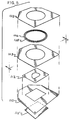
- FIG. 5 is an exploded isometric view of the fluid control apparatus shown in FIG. 1.
- FIG. 6 is a side view of the exploded fluid control apparatus construction depicted in FIG. 5.
- FIG. 7 is an isometric view of the fluid control apparatus portion of FIG. 1, shown installed on a portion of a surgical drape.
- FIG. 8 is a partially broken away exploded isometric view, similar to FIG. 5, of an alternative construction of a portion of the present invention.
- FIG. 9 is a top plan view, similar to FIG. 3, of an alternative design of the present invention.
- the fluid control apparatus is comprised of a top sheet 102, which is preferably thin pliable sheet of fluid impervious material, which is most preferably substantially transparent.
- the top sheet 102 has an opening, thus creating both an outer perimetric edge and an interior perimetric edge 104, the latter defining the opening.
- Affixed to the top sheet 102 near the interior perimetric edge is at least one elongated, flexible, bendable support element 106 adjacent to and substantially completely surrounding the interior perimetric edge.
- the thin bendable element 106 is preferably comprised of a plastic encased wire, similar to the construction of a twist tie typically used as a closure device for various types of bags.
- a second thin bendable element 108 is also provided.
- the bendable elements 106,108 are preferably placed in contact with one of the surfaces of the top sheet 102 and are held in place by a number of techniques, for example, they may be affixed using adhesives, or by heat sealing the bendable elements 106,108 to the top sheet or to the top sheet 102 and an intermediate sheet 103 of similar material.
- the bendable elements 106,108 are constructed from a wire having a sufficiently heavy gauge to maintain the edge of the opening in the top sheet in place and in a configuration which promotes fluid collection. By manipulating the bendable elements, it is possible to form the edge of the top sheet into an upwardly depending lip and the bendable means will retain it in such a position, preventing fluid from flowing over this edge on to the top sheet 102.
- the bendable elements 106, 108 of the present invention create a relatively more rigid and shape retentive section along the inner perimetric edge 104 of this section of the fluid collection device.
- Numerous materials and constructions can be substituted to achieve a similar effect.
- certain shape retentive foam materials could be formed in thin strips or narrow annular sections and disposed in the manner of the bendable elements 106, 108 shown. It is preferred, however, that a plastic encased wire as described be used.
- the fluid control apparatus of the present invention also comprises a bottom sheet 110, which preferably is also comprised of a thin pliable sheet of material.
- the bottom sheet 110 also has a fenestration section 112 which is placed into contact with the patient.
- the fenestration section has an interior perimetric edge 114 which defines the fenestration through which the surgeon may access the patient during a procedure.
- the side of the fenestration section which contacts the patient is coated with an adhesive material.
- either the fenestration section or the entire patient facing bottom sheet may be coated with an anti-microbial coating.
- This coating may be in addition to an adhesive or may be used alone, for example, only the fenestration section might be coated with adhesive, while the fenestration section 112 and the rest of the bottom sheet, i.e. the entire bottom sheet 110 may be coated with an anti-microbial product.
- One such coating is Micro-SideTM which is comprised of polyhexamethylenebiguanide (PHMB).
- PHMB polyhexamethylenebiguanide
- one or more drainage ports 120 are provided in the bottom sheet 110 in order to facilitate the removal of the collected fluid from the fluid collection device 110 illustrated.
- the fenestration section 112 may be integral with the bottom sheet 110.
- the present invention keeps the fluid contained within the top and bottom sheets, which are sealed together in a liquid tight relationship to form a container, i.e. a pouch.
- a container i.e. a pouch.
- the bendable elements do not substantially inhibit the characteristics of the surrounding thin pliable sheets 102, 110 and further provide a structure which adds very little bulk when the device is folded and packaged.
- the top sheet 102 also preferably comprises an intermediate sheet of thin pliable material 103.
- the top sheet 102 and intermediate sheet 103 are thermally bonded in the region of the interior perimetric edge to retain the bendable elements 106, 108 in place and also at the outer edge of the device thereby creating a liquid tight seal between the top sheet 102, the intermediate sheet 103 and the bottom sheet 110.
- the construction of the region near the interior edge 104 of the top sheet is shown in the enlarged view of Fig. 2A.
- the bendable means 106, 108 are spaced apart from each other and the edge 104 of the opening, and are sealed between the top sheet 102 and intermediate sheet 103. In certain embodiments, it may be preferable to use a single bendable means or to replace the encased wire depicted with other shapes or materials.
- the design of the bendable means will depend largely upon the material characteristics and thickness of the top sheet 102 and intermediate sheet 103, as well as the overall size of the fluid collection device 100 and the opening.
- the bottom sheet 110 preferably surrounds an adhesive fenestration section 112.
- the bottom sheet 110 and fenestration section 112 are preferably heat sealed or otherwise affixed to provide a liquid tight seal at their juncture.
- the bottom sheet 110 is comprised of a substantially opaque portion, while the fenestration section 112 and the adhesive disposed thereon are substantially transparent.
- a protective covering, such as release paper 115 overlies the adhesive on the fenestration section 112 and is removed prior to use, as shown by the arrow in FIG 2.
- FIG. 3 A top plan view of a preferred embodiment of the fluid collection device 100 of the present invention is depicted in FIG. 3.
- the device 100 shown is particularly adapted for use in a procedure such as a Caesarean section delivery, during which a relatively large quantity of fluids and other materials are released and must be channeled away from the incision and collected. Accordingly, the present invention provides the capability to collect fluids around the entire perimeter of the incision--that is, 360 degree collection.
- the device 100 is most preferably in the substantially square or rectangular, having two comers removed at about a 45 degree angle, resulting in the shape shown. Numerous other overall shapes will be useful, however, depending upon the application for a particular surgical procedure.
- the fenestration section 112 will be placed into substantially fluid tight contact with the portion of the patient surrounding the incision site. Fluids will flow from all directions on to the top surface of the fluid impervious sheet which comprises the fenestration section 112 and the bottom sheet 110.
- the drainage ports 120 are located to take best advantage of gravity when the fluid collection apparatus is placed on the patient. In the case of the preferred embodiment shown, the drainage ports 120 are located in the corners of one side of the device, where the fluids and materials will collect and be drained. Although visible in this view because the top sheet 102 is preferably transparent, the drainage ports 120 are disposed on the bottom sheet 110. Also, in the preferred embodiment shown, the fenestration section 112 is slightly offset from the opening in the top sheet. This design is preferred since the incision made for a Caesarean section is typically offset from the central medial plane of the patient, therefore the fenestration is disposed at an offset position while the collection device itself remains substantially atop the patient.
- FIG. 4 a bottom plan view of a preferred embodiment of a fluid collection device 100 made in accordance with the present invention is shown. As set forth above, the drainage ports 120 which are located on the bottom sheet 110 are seen in this view.
- the fenestration section 112, upon which adhesive is preferably applied is also shown. Since the fenestration section 112 is preferably transparent, the intermediate sheet 103 and the top sheet 102, as well as the bendable elements 106,108 are all visible in Figure 4.
- bendable means 106,108 are disposed between the top sheet 102 and intermediate sheet 103, which are then preferably bonded together by heat sealing or applying adhesives in at least the region of the bendable means 106,108, thereby embedding them in place.
- the bottom section is formed by affixing the fenestration section 112 to one side of the bottom sheet 110, again preferably by heat sealing or applying an adhesive.
- the side of the fenestration section 112 placed into contact with the bottom sheet 110 is the side which preferably has adhesive disposed thereon. Accordingly, release paper 115 is placed over the adhesive and removed prior to use.
- the drainage ports 120 are also installed on the bottom sheet 110.
- the upper and lower sections are then joined and a liquid impervious seal is formed about the outer perimetric edges of the top sheet 102, the intermediate sheet 103 and the bottom sheet 110, resulting in a complete fluid collection device, substantially as depicted in FIG. 1.
- FIG. 6 A side view of the construction described in FIG. 5, taken along line 6-6, is shown in FIG. 6.
- the first sheet 102, intermediate sheet 103 and bendable means 106,108 are disposed atop one another and form an upper section of the device.
- the bottom sheet 110, fenestration section 112 and cover paper 115 form a lower section.
- the upper section and lower section are preferably then joined and sealed around their outer perimetric edges to form a complete fluid collection device 100.
- fluid collection device 100 may be used alone as a fluid control product, it is also a preferred embodiment of the present invention to incorporate the fluid collection device 100 into a drape or other structure which covers the patient. As shown in isometric view in FIG. 7, an obstetric drape 200 for use during procedures such as a Caesarean sections is provided by the present invention.
- a fluid collection device 100 is disposed upon and attached to the surface of a drape 210. As well known to those of ordinary skill, numerous materials can be utilized as surgical drapes including woven and nonwoven fabrics and polymeric materials. In a preferred embodiment an instrument pad 220 is also disposed upon the top surface of the drape 210.
- the instrument pad provides a reinforced section and preferably absorbent surface upon which instruments or other objects may rest during the procedure.
- the instrument pad 220 is also provided with one or more means for retaining a drainage tube 222.
- a tube will connect the drainage ports 120 with a remote collection receptacle (not shown).
- the retaining means 222 are provided to keep the tube in proper position and away from the area of the incision.
- the fluid collection device 100 is preferably affixed to the drape 220 substantially along the along the dashed line 230 shown in FIG. 7.
- the drape material retains the same degree of conformability to the patient, except in a small area near the fenestration section 112.
- such a construction is advantageous, particularly as the fluid collection device becomes filled with fluid, since it may move relative to the drape material 210 and, thus will not substantially shift or otherwise affect the position of the drape.
- the drainage port protrudes from the bottom sheet 110 and is preferably located over the instrument pad 220 when in use.
- the top section may be formed as shown in FIG. 8.
- the bendable means 106,108 may be contained between the top sheet 102 and an annular layer 105, which replaces the intermediate sheet 103 described above.
- the top section will therefore comprise two layers only in the region surrounding the interior perimetric edge where the bendable means 106,108 are disposed. The desirability of this type of construction is again determined by the thickness and other characteristics of the materials used, and the particular application for the drape being designed.
- FIG. 9 and alternate design of the fluid collection device 100 of the present invention is shown in a top plan view, similar to that of FIG. 3.
- the interior perimetric edge 104 of the top sheet 102 and intermediate sheet 103 (or annular section 105), as well as the bendable means 106,108 are substantially octagonally shaped.
- this design might be preferred because the sides of the opening in the top section are substantially parallel to five of the sides of the outer perimetric edge of the device. Therefore, improved draping characteristics and improved stability and uniformity in the performance of the bendable means to keep the opening properly positioned above the bottom sheet 110 and fenestration section 112 are obtained.
Description
- The present invention relates to devices for collecting fluid from a patient and more particularly to surgical drapes having means for collecting and controlling the fluids which accumulate during surgical procedures, such as Caesarian section deliveries.
- During most surgical procedures blood and other body fluids are released. Additionally, most procedures require some irrigation, resulting in additional fluid in the area of the incision. Many times it is impractical to collect and control this fluid using suction, and therefore the fluid is permitted to seep into the area surrounding the incision or location where the procedure produces a fluid flow. Surgical drapes comprising a sheet of flexible material having a fenestration and a spaced apart region for collecting the fluids and materials emanating from the patient during the surgical procedure are well known. For example, U.S. Patent 4,462,396--Wichman discloses a drape having a flexible pocket secured to top surface of a drape. A fitting attached to the pocket permits a tube to be utilized to drain the pocket of the fluids collected. Similarly, U.S. Patent 4,559,937 - Vinson and U.S. Patent 4,598,458 - McAllester disclose surgical drapes having fluid collection bags spaced at a location whereby the fluid will flow by gravity and be collected and stored.
- Although fluid collection and control is important in most surgical procedures, many gynaecological and obstetric procedures pose particularly difficult problems. In the past, others have attempted to provide fluid collection means particularly adapted to collecting these such fluid flows. A surgical drape for cystoscopic procedures having a fenestration and a folded pocket located in the path of the fluid runoff is disclosed in U.S. Patent 4,414,968 - Amin. Although using apparatus separate from the surgical drape itself, a method of collecting postpartum fluid is disclosed in U.S. Patent 4,105,019 - Haswell. The method disclosed utilizes a sheet-like receptacle having two pockets one for collecting amniotic fluid and one for collecting blood. A fluid collection apron for use during transurethral resection is disclosed in U.S. Patent 4,007,741 - Waldrop, et al. The apron is attached to the urological operating table and to the surgeon's neck. The apron collects fluid and drains it through a tube into a remote collection receptacle.
- US-A-4890628 discloses a surgical drape with means for channeling and collecting fluids. Also disclosed is the use of malleable strips which are intended to hold the channeling and collecting means in the appropriate configuration.
- In addition to the specific examples discussed above, it is also well known within the art to design surgical drapes and the like to be particularly adapted to operations performed on certain body portions, and indeed, adapted to specific procedures. For example, in the case of the ear, specific drainage devices for collecting fluid and channeling the fluid to a remote receptacle have been disclosed in U.S. Patent 4,036,235--Hathaway and U.S. Patent 4,201,212--Bradley. Both designs rely upon the patient being in an upright position, providing a fenestration disposed above a fluid collection pouch, thereby providing a gravity flow generally the patient into the collection pouch.
- One disadvantage to the methods and apparatus disclosed immediately above is that the fluid collection pouch is spaced or disposed on the patient in a manner which relies on patient orientation to provide a gravity flow in a particular direction. Thus, if the patient were to shift or if the surgeon required the patient to be reoriented, it would also be necessary to re-orient the drape and fluid collection apparatus to some extent. A solution to this problem is provided by U.S. patent 3,650,267--Anderson, which discloses a surgical drape having a fluid collection means surrounding the area adjacent to the fenestration. The apparatus disclosed consists of a very thin flexible bag having a fenestration formed in its bottom and preferably having a rim of elastic or other material sewn to the upper portion which forms an open end. In certain embodiments a tubular drain is integrated into the fluid collector. One problem with such a device, however, is that the edges of the bag tend to become matted down during the procedure, resulting in fluid spillage.
- It therefore would be desireable to provide a fluid collection device which could be readily integrated into a variety of drapes and adapted to a variety of procedures. Such a drape would preferably collect fluids and other materials from the entire periphery of an incision wound or fluid source and would not rely substantially upon the exact orientation of the patient.
- Accordingly, it has now been found that a device for collecting fluids from a patient which overcomes the problems associated with previous designs, while improving the efficiency of fluid collection and providing an enhanced surgical site can be constructed. The apparatus disclosed by the present invention provides one or more elongated bendable means extending longitudinally substantially along the inner perimetric edge of a thin pliable sheet of liquid impervious material. The device comprises a first sheet of liquid impervious material having an opening. The first sheet is attached to a bottom sheet of liquid impervious material having a fenestration for access to the patient. The bendable means retain the inner perimetric edge of an opening in the top sheet in a defined shape, improving fluid collection and access. The bendable means are preferably formed of a metallic section embedded in a cover, such as a wire covered by a pliable plastic material.
- Preferably, the bendable means are encased by providing an intermediate sheet of liquid impervious material and placing the bendable means between the first and intermediate sheets. The intermediate sheet may be in registration with the first sheet and secured in a liquid tight relationship at least along the inner and outer perimetric edges. Alternatively, the intermediate sheet may be comprised of an annular section of material, secured in a liquid tight relationship to the first sheet along the inner perimetric edge. Preferably, the sheets are secured by heat sealing. In certain embodiments the fenestration section is secured to the bottom sheet in a liquid tight relationship, preferably by heat sealing.
- In a preferred embodiment, a portion of said bottom sheet is coated with adhesive on said patient facing side and most preferably, the fenestration section is coated with adhesive. Certain embodiments also comprise drainage ports for transmitting fluids which are affixed to the bottom side.
- The present invention also provides a surgical drape for overlying a patient comprising a sheet of drape material having at least one opening for access to the patient and having a device for collecting fluids as described above attached thereto. Drapes disclosed also comprise a pad of absorbent material overlying said drape material and means for retaining a drainage tube. Methods of manufacturing a fluid collecting device are also disclosed.
- FIG. 1 is an isometric view of a fluid control apparatus made in accordance with the present invention.
- FIG. 2 is a cross-section of the fluid control apparatus of FIG. 1, taken along line 2-2.
- FIG. 2A is an enlarged view of a portion of the fluid control apparatus shown in FIG. 2.
- FIG. 3 is a top plan view of the apparatus shown in FIG. 1.
- FIG. 4 is a bottom plan view of the apparatus shown in FIG. 1.
- FIG. 5 is an exploded isometric view of the fluid control apparatus shown in FIG. 1.
- FIG. 6 is a side view of the exploded fluid control apparatus construction depicted in FIG. 5.
- FIG. 7 is an isometric view of the fluid control apparatus portion of FIG. 1, shown installed on a portion of a surgical drape.
- FIG. 8 is a partially broken away exploded isometric view, similar to FIG. 5, of an alternative construction of a portion of the present invention.
- FIG. 9 is a top plan view, similar to FIG. 3, of an alternative design of the present invention.
- Referring to FIG. 1 an isometric view of
fluid control apparatus 100 made in accordance with the present invention is shown. The fluid control apparatus is comprised of atop sheet 102, which is preferably thin pliable sheet of fluid impervious material, which is most preferably substantially transparent. Thetop sheet 102 has an opening, thus creating both an outer perimetric edge and an interiorperimetric edge 104, the latter defining the opening. Affixed to thetop sheet 102 near the interior perimetric edge is at least one elongated, flexible,bendable support element 106 adjacent to and substantially completely surrounding the interior perimetric edge. The thinbendable element 106 is preferably comprised of a plastic encased wire, similar to the construction of a twist tie typically used as a closure device for various types of bags. As shown in FIG. 1, in a preferred embodiment, a second thinbendable element 108 is also provided. - The bendable elements 106,108 are preferably placed in contact with one of the surfaces of the
top sheet 102 and are held in place by a number of techniques, for example, they may be affixed using adhesives, or by heat sealing the bendable elements 106,108 to the top sheet or to thetop sheet 102 and anintermediate sheet 103 of similar material. The bendable elements 106,108 are constructed from a wire having a sufficiently heavy gauge to maintain the edge of the opening in the top sheet in place and in a configuration which promotes fluid collection. By manipulating the bendable elements, it is possible to form the edge of the top sheet into an upwardly depending lip and the bendable means will retain it in such a position, preventing fluid from flowing over this edge on to thetop sheet 102. - The
bendable elements perimetric edge 104 of this section of the fluid collection device. Numerous materials and constructions can be substituted to achieve a similar effect. For example, certain shape retentive foam materials could be formed in thin strips or narrow annular sections and disposed in the manner of thebendable elements - As will be explained in further detail below, the fluid control apparatus of the present invention also comprises a
bottom sheet 110, which preferably is also comprised of a thin pliable sheet of material. Thebottom sheet 110 also has afenestration section 112 which is placed into contact with the patient. The fenestration section has an interiorperimetric edge 114 which defines the fenestration through which the surgeon may access the patient during a procedure. Preferably, the side of the fenestration section which contacts the patient is coated with an adhesive material. In certain embodiments, either the fenestration section or the entire patient facing bottom sheet may be coated with an anti-microbial coating. This coating may be in addition to an adhesive or may be used alone, for example, only the fenestration section might be coated with adhesive, while thefenestration section 112 and the rest of the bottom sheet, i.e. theentire bottom sheet 110 may be coated with an anti-microbial product. One such coating is Micro-Side™ which is comprised of polyhexamethylenebiguanide (PHMB). Also, one ormore drainage ports 120 are provided in thebottom sheet 110 in order to facilitate the removal of the collected fluid from thefluid collection device 110 illustrated. In certain embodiments, thefenestration section 112 may be integral with thebottom sheet 110. - The present invention keeps the fluid contained within the top and bottom sheets, which are sealed together in a liquid tight relationship to form a container, i.e. a pouch. However, unlike a more rigid structure, the bendable elements do not substantially inhibit the characteristics of the surrounding thin
pliable sheets - Further details of the construction of the fluid collection device depicted in Fig. 1 are seen in the cross-sectional view of Fig. 2. As shown, the
top sheet 102 also preferably comprises an intermediate sheet of thinpliable material 103. In a preferred embodiment, thetop sheet 102 andintermediate sheet 103 are thermally bonded in the region of the interior perimetric edge to retain thebendable elements top sheet 102, theintermediate sheet 103 and thebottom sheet 110. The construction of the region near theinterior edge 104 of the top sheet is shown in the enlarged view of Fig. 2A. The bendable means 106, 108 are spaced apart from each other and theedge 104 of the opening, and are sealed between thetop sheet 102 andintermediate sheet 103. In certain embodiments, it may be preferable to use a single bendable means or to replace the encased wire depicted with other shapes or materials. The design of the bendable means will depend largely upon the material characteristics and thickness of thetop sheet 102 andintermediate sheet 103, as well as the overall size of thefluid collection device 100 and the opening. - Referring again to FIG. 2, the construction of the lower section of the fluid collection device of the present invention is shown. The
bottom sheet 110 preferably surrounds anadhesive fenestration section 112. Thebottom sheet 110 andfenestration section 112 are preferably heat sealed or otherwise affixed to provide a liquid tight seal at their juncture. In a preferred embodiment, thebottom sheet 110 is comprised of a substantially opaque portion, while thefenestration section 112 and the adhesive disposed thereon are substantially transparent. A protective covering, such asrelease paper 115 overlies the adhesive on thefenestration section 112 and is removed prior to use, as shown by the arrow in FIG 2. - A top plan view of a preferred embodiment of the
fluid collection device 100 of the present invention is depicted in FIG. 3. Thedevice 100 shown is particularly adapted for use in a procedure such as a Caesarean section delivery, during which a relatively large quantity of fluids and other materials are released and must be channeled away from the incision and collected. Accordingly, the present invention provides the capability to collect fluids around the entire perimeter of the incision--that is, 360 degree collection. Thedevice 100 is most preferably in the substantially square or rectangular, having two comers removed at about a 45 degree angle, resulting in the shape shown. Numerous other overall shapes will be useful, however, depending upon the application for a particular surgical procedure. In use, thefenestration section 112 will be placed into substantially fluid tight contact with the portion of the patient surrounding the incision site. Fluids will flow from all directions on to the top surface of the fluid impervious sheet which comprises thefenestration section 112 and thebottom sheet 110. Most preferably, thedrainage ports 120 are located to take best advantage of gravity when the fluid collection apparatus is placed on the patient. In the case of the preferred embodiment shown, thedrainage ports 120 are located in the corners of one side of the device, where the fluids and materials will collect and be drained. Although visible in this view because thetop sheet 102 is preferably transparent, thedrainage ports 120 are disposed on thebottom sheet 110. Also, in the preferred embodiment shown, thefenestration section 112 is slightly offset from the opening in the top sheet. This design is preferred since the incision made for a Caesarean section is typically offset from the central medial plane of the patient, therefore the fenestration is disposed at an offset position while the collection device itself remains substantially atop the patient. - Referring to FIG. 4, a bottom plan view of a preferred embodiment of a
fluid collection device 100 made in accordance with the present invention is shown. As set forth above, thedrainage ports 120 which are located on thebottom sheet 110 are seen in this view. Thefenestration section 112, upon which adhesive is preferably applied is also shown. Since thefenestration section 112 is preferably transparent, theintermediate sheet 103 and thetop sheet 102, as well as the bendable elements 106,108 are all visible in Figure 4. - The placement of the components which form the preferred embodiment of the fluid collection device made in accordance with the present invention are shown in the exploded isometric view of FIG. 5. Preferably, bendable means 106,108 are disposed between the
top sheet 102 andintermediate sheet 103, which are then preferably bonded together by heat sealing or applying adhesives in at least the region of the bendable means 106,108, thereby embedding them in place. The bottom section is formed by affixing thefenestration section 112 to one side of thebottom sheet 110, again preferably by heat sealing or applying an adhesive. The side of thefenestration section 112 placed into contact with thebottom sheet 110 is the side which preferably has adhesive disposed thereon. Accordingly,release paper 115 is placed over the adhesive and removed prior to use. Thedrainage ports 120 are also installed on thebottom sheet 110. The upper and lower sections are then joined and a liquid impervious seal is formed about the outer perimetric edges of thetop sheet 102, theintermediate sheet 103 and thebottom sheet 110, resulting in a complete fluid collection device, substantially as depicted in FIG. 1. - A side view of the construction described in FIG. 5, taken along line 6-6, is shown in FIG. 6. As shown by the single connecting lines, the
first sheet 102,intermediate sheet 103 and bendable means 106,108 are disposed atop one another and form an upper section of the device. Thebottom sheet 110,fenestration section 112 andcover paper 115 form a lower section. As indicated by the double connecting lines, the upper section and lower section are preferably then joined and sealed around their outer perimetric edges to form a completefluid collection device 100. - Although the
fluid collection device 100 described above with reference to FIGS. 1-6 may be used alone as a fluid control product, it is also a preferred embodiment of the present invention to incorporate thefluid collection device 100 into a drape or other structure which covers the patient. As shown in isometric view in FIG. 7, anobstetric drape 200 for use during procedures such as a Caesarean sections is provided by the present invention. Afluid collection device 100 is disposed upon and attached to the surface of adrape 210. As well known to those of ordinary skill, numerous materials can be utilized as surgical drapes including woven and nonwoven fabrics and polymeric materials. In a preferred embodiment aninstrument pad 220 is also disposed upon the top surface of thedrape 210. The instrument pad provides a reinforced section and preferably absorbent surface upon which instruments or other objects may rest during the procedure. Theinstrument pad 220 is also provided with one or more means for retaining adrainage tube 222. Preferably, while in use, a tube will connect thedrainage ports 120 with a remote collection receptacle (not shown). The retaining means 222 are provided to keep the tube in proper position and away from the area of the incision. - The
fluid collection device 100 is preferably affixed to thedrape 220 substantially along the along the dashedline 230 shown in FIG. 7. By affixing thefluid collection device 100 to thedrape surface 210 in this manner, the characteristics of the drape material are not affected by the fluid collection device. In other words, the drape material retains the same degree of conformability to the patient, except in a small area near thefenestration section 112. As easily envisioned by those of ordinary skill, such a construction is advantageous, particularly as the fluid collection device becomes filled with fluid, since it may move relative to thedrape material 210 and, thus will not substantially shift or otherwise affect the position of the drape. As seen by the upturned corner illustrated in FIG. 7, The drainage port protrudes from thebottom sheet 110 and is preferably located over theinstrument pad 220 when in use. - As an alternative to the construction disclosed above with reference to FIGs. 1-6, the top section may be formed as shown in FIG. 8. As shown in a partial exploded isometric view, similar to FIG. 5, the bendable means 106,108 may be contained between the
top sheet 102 and anannular layer 105, which replaces theintermediate sheet 103 described above. In this embodiment, the top section will therefore comprise two layers only in the region surrounding the interior perimetric edge where the bendable means 106,108 are disposed. The desirability of this type of construction is again determined by the thickness and other characteristics of the materials used, and the particular application for the drape being designed. - Referring to FIG. 9 and alternate design of the
fluid collection device 100 of the present invention is shown in a top plan view, similar to that of FIG. 3. In this embodiment, the interiorperimetric edge 104 of thetop sheet 102 and intermediate sheet 103 (or annular section 105), as well as the bendable means 106,108 are substantially octagonally shaped. In certain applications, this design might be preferred because the sides of the opening in the top section are substantially parallel to five of the sides of the outer perimetric edge of the device. Therefore, improved draping characteristics and improved stability and uniformity in the performance of the bendable means to keep the opening properly positioned above thebottom sheet 110 andfenestration section 112 are obtained. - Numerous variations to the invention disclosed above will present themselves to those of ordinary skill. Accordingly, reference should be made to the appended claims in order to determine the scope of the present invention.
Claims (10)
- A device for collecting fluids from a patient comprising:a top sheet (102) of liquid impervious material having an outer perimetric edge and an opening defined by an inner perimetric edge (104), said outer perimetric edge completely surrounding said inner perimetric edge;a bottom sheet (110) of liquid impervious material comprising a fenestration for access to the patient, said bottom sheet being secured to said top sheet (102) in a liquid tight relationship outwardly of the inner perimetric edge (104) of said top sheet; andone or more elongated bendable means (106, 108) extending longitudinally substantially along said inner perimetric edge (104), whereby said bendable means retain said inner perimetric edge in a defined shape.
- The device of claim 1, further comprising an intermediate sheet (103) of liquid impervious material and wherein said bendable means (106, 108) are disposed between said top sheet (102) and said intermediate sheet (103).
- The device of claim 2, wherein said intermediate sheet (103) is substantially in registration with said top sheet (102) and said top and intermediate sheets are secured to each other in a liquid tight relationship at least along said inner perimetric edge (104) and said outer perimetric edge.
- The device of any preceding claim, wherein at least a portion of said bottom sheet (110) is coated with adhesive on the side opposite to said top sheet (102).
- The device of claim 4, further comprising an anti-microbial coating applied on the side opposite to said top sheet (102).
- The device of any preceding claim, further comprising at least one drainage port means for transmitting fluid affixed to said bottom sheet (110).
- A surgical drape for overlying a patient comprising:a sheet of drape material (210) having at least one opening therein for access to the patient; anda device according to any preceding claim, attached to said drape material and overlying said opening.
- The surgical drape of claim 7, further comprising means for retaining a drainage tube.
- A disposable surgical drape according to claim 7.
- A method of manufacturing a fluid collecting device comprising the steps of:providing a top (102) and an intermediate (103) sheet of thin pliable liquid impervious material and at least one elongated bendable means (106, 108), said top sheet having an outer perimetric edge and an opening defined by an inner perimetric edge (104), said outer perimetric edge surrounding said inner perimetric edge;forming an upper section by securing said bendable means between said first and intermediate sheets substantially along said inner perimetric edge (104) to create a liquid tight seal;providing a bottom sheet (110) and a fenestration section (112) comprised of thin pliable liquid impervious material;forming a lower section by securing said bottom sheet and said fenestration section to create a liquid tight seal;securing said upper section and said lower section together to form a liquid tight seal.
Applications Claiming Priority (2)
| Application Number | Priority Date | Filing Date | Title |
|---|---|---|---|
| US07/493,567 US5161544A (en) | 1990-03-14 | 1990-03-14 | Surgical drape having 360 degree fluid control |
| US493567 | 1990-03-14 |
Publications (2)
| Publication Number | Publication Date |
|---|---|
| EP0447217A1 EP0447217A1 (en) | 1991-09-18 |
| EP0447217B1 true EP0447217B1 (en) | 1997-05-14 |
Family
ID=23960771
Family Applications (1)
| Application Number | Title | Priority Date | Filing Date |
|---|---|---|---|
| EP91302132A Expired - Lifetime EP0447217B1 (en) | 1990-03-14 | 1991-03-13 | Surgical drape having 360 degree fluid control |
Country Status (13)
| Country | Link |
|---|---|
| US (1) | US5161544A (en) |
| EP (1) | EP0447217B1 (en) |
| JP (1) | JP3222152B2 (en) |
| KR (1) | KR0167561B1 (en) |
| AU (1) | AU636461B2 (en) |
| BR (1) | BR9101002A (en) |
| CA (1) | CA2038064C (en) |
| DE (1) | DE69126054T2 (en) |
| ES (1) | ES2103776T3 (en) |
| HK (1) | HK122097A (en) |
| MY (1) | MY105456A (en) |
| NZ (1) | NZ237284A (en) |
| ZA (1) | ZA911852B (en) |
Cited By (1)
| Publication number | Priority date | Publication date | Assignee | Title |
|---|---|---|---|---|
| KR200484738Y1 (en) * | 2017-08-25 | 2017-11-15 | 김계훈 | Face cover for dental clinic |
Families Citing this family (42)
| Publication number | Priority date | Publication date | Assignee | Title |
|---|---|---|---|---|
| CA2070590C (en) * | 1991-12-16 | 2002-10-01 | Kimberly-Clark Worldwide, Inc. | Surgical fluid evacuation system |
| US5640975A (en) * | 1993-02-16 | 1997-06-24 | Diao; Edward | Surgical drape for use in upper extremity operations |
| US5345946A (en) * | 1993-04-23 | 1994-09-13 | Johnson & Johnson Medical, Inc. | Multi-element surgical drape with sealable surgical run-off pouches |
| US6213124B1 (en) * | 1993-04-23 | 2001-04-10 | Johnson & Johnson Medical, Inc. | Surgical drape with a sealable pouch |
| US5713372A (en) * | 1993-09-27 | 1998-02-03 | Tecnol Medical Products, Inc. | Fluid control pad with pouches |
| SE9303324L (en) * | 1993-10-11 | 1995-04-12 | Moelnlycke Ab | A surgical drape |
| US5494050A (en) * | 1994-06-01 | 1996-02-27 | Baxter International Inc. | Arthroscopy pouch |
| US5464024A (en) * | 1994-07-05 | 1995-11-07 | Standard Textile Co., Inc. | Reusable surgical drape with fluid-retaining trough |
| US5797402A (en) * | 1994-07-06 | 1998-08-25 | West; Raymond O. | Disposable drape for medical examination |
| US5568817A (en) * | 1995-05-31 | 1996-10-29 | Harty; Robert D. | Compact device for controlling runoff of fluid |
| US6070586A (en) * | 1996-06-05 | 2000-06-06 | Lingeman Medical Products, Inc. | Fluid control drape with conforming lip |
| US5778889A (en) * | 1996-08-30 | 1998-07-14 | Kimberly-Clark Worldwide, Inc. | Craniotomy drape |
| US6032670A (en) * | 1997-05-21 | 2000-03-07 | Miller; Mark T. | Surgical drape for shoulder procedures |
| US6290685B1 (en) | 1998-06-18 | 2001-09-18 | 3M Innovative Properties Company | Microchanneled active fluid transport devices |
| US6420622B1 (en) * | 1997-08-01 | 2002-07-16 | 3M Innovative Properties Company | Medical article having fluid control film |
| US5778891A (en) * | 1997-08-25 | 1998-07-14 | Missy D. Margolis | Surgical drape |
| US5947122A (en) * | 1998-01-16 | 1999-09-07 | Mentor Corporation | Fluid collection drape |
| US6824853B1 (en) * | 2000-10-18 | 2004-11-30 | Alpha Scientific Corporation | Pliable pad for collecting and absorbing liquids |
| US20020146955A1 (en) * | 2000-10-18 | 2002-10-10 | Levine Daniel S. | Pliable pad for collecting and absorbing liquids |
| GB0216413D0 (en) * | 2002-07-15 | 2002-08-21 | Nestle Sa | Tabletted chewing gum sweet |
| US7625362B2 (en) | 2003-09-16 | 2009-12-01 | Boehringer Technologies, L.P. | Apparatus and method for suction-assisted wound healing |
| US7815616B2 (en) | 2002-09-16 | 2010-10-19 | Boehringer Technologies, L.P. | Device for treating a wound |
| US6755196B2 (en) * | 2002-09-27 | 2004-06-29 | Emilio Musso | Irrigation drape |
| WO2004045479A1 (en) * | 2002-11-18 | 2004-06-03 | Uni-Charm Corporation | Absorbable article |
| ATE405170T1 (en) * | 2003-05-06 | 2008-09-15 | Gumlink As | METHOD FOR PRODUCING CHEWING GUM GRANULES AND COMPRESSED CHEWING GUM PRODUCTS, AND A CHEWING GUM GRANULATING SYSTEM |
| DK1474995T3 (en) | 2003-05-06 | 2013-02-18 | Gumlink As | Process for the preparation of chewing gum granules, a rubber composition extruder and granulation system and a chewing gum product |
| US7942866B2 (en) | 2003-08-28 | 2011-05-17 | Boehringer Technologies, L.P. | Device for treating a wound |
| US7275544B2 (en) * | 2003-12-01 | 2007-10-02 | Michael Gil | Covering for an aseptic treatment site |
| US7290547B2 (en) * | 2003-12-01 | 2007-11-06 | Joseph Hare | Covering for an aseptic treatment site |
| DK200401195A (en) * | 2004-08-06 | 2004-08-06 | Gumlink As | Layered chewing gum tablet has layer comprising gum base in compressed gum granules having specified average diameter |
| US7594512B2 (en) | 2005-10-07 | 2009-09-29 | Allegiance Corporation | Fenestrated extremity surgical drape |
| US8079365B2 (en) * | 2007-05-15 | 2011-12-20 | Allegiance Corporation | Surgical drape with position assisting fenestration |
| JP2009118934A (en) * | 2007-11-13 | 2009-06-04 | Nippon Medical Products Co Ltd | Cover cloth used in operation at obstetrical-gynecological |
| US20100022990A1 (en) * | 2008-07-25 | 2010-01-28 | Boehringer Technologies, L.P. | Pump system for negative pressure wound therapy and improvements thereon |
| JP5414054B2 (en) * | 2010-02-08 | 2014-02-12 | 株式会社リブドゥコーポレーション | drape |
| US8641694B2 (en) | 2010-06-29 | 2014-02-04 | Microtek Medical, Inc. | Fluid containment pouch |
| US8833707B2 (en) | 2010-07-15 | 2014-09-16 | Allen Medical Systems, Inc. | Disposable urology drainage bag |
| US10111724B2 (en) * | 2015-01-13 | 2018-10-30 | David Schwartz | Surgical drape for use in cesarean sections |
| AU2016342178B2 (en) * | 2015-10-20 | 2021-07-08 | Allegiance Corporation | Surgical drape with attachable fluid control pouch and geometric alignment feature |
| WO2017196566A1 (en) * | 2016-05-12 | 2017-11-16 | 3M Innovative Properties Company | Surgical drape with transparent sheet |
| USD810949S1 (en) * | 2016-07-11 | 2018-02-20 | Beaver-Visitec International (Us), Inc. | Surgical drape |
| WO2021001694A1 (en) * | 2019-07-03 | 2021-01-07 | Clínica Médica Trina Ltda | Constructive arrangement applied to surgical field for cesarean delivery |
Family Cites Families (20)
| Publication number | Priority date | Publication date | Assignee | Title |
|---|---|---|---|---|
| US3650267A (en) * | 1970-02-12 | 1972-03-21 | Johnson & Johnson | Surgical drape |
| US3667458A (en) * | 1970-03-02 | 1972-06-06 | Kimberly Clark Co | Surgical drape sheet |
| GB1386800A (en) * | 1971-10-27 | 1975-03-12 | Johnson & Johnson | Self-adhesive disposable surgical drape |
| US3923052A (en) * | 1972-06-06 | 1975-12-02 | Kendall & Co | Conformable surgical drape |
| US4007741A (en) * | 1975-04-11 | 1977-02-15 | Waldrop Rayburn C | Transurethral resection apron system |
| US4036235A (en) * | 1975-06-04 | 1977-07-19 | Lucille Hathaway | Drainage device for ear irrigation |
| US4076017A (en) * | 1976-02-11 | 1978-02-28 | Haswell John N | Postpartum fluid loss receptacle |
| GB1578282A (en) * | 1977-03-24 | 1980-11-05 | Bradley M | Surgical apparatus |
| US4378794A (en) * | 1981-01-07 | 1983-04-05 | The Kendall Company | Surgical drape |
| US4414968A (en) * | 1981-05-29 | 1983-11-15 | Amin Shailesh R | Surgical drape |
| US4462396A (en) * | 1983-01-27 | 1984-07-31 | The Kendall Company | Surgical drape |
| US4598458A (en) * | 1983-04-27 | 1986-07-08 | The Kendall Company | Surgical drape with fluid collection bag |
| US4559937A (en) * | 1983-04-27 | 1985-12-24 | The Kendall Company | Fluid collection bag with a screen for a surgical drape |
| US4570628A (en) * | 1984-02-13 | 1986-02-18 | Neal Richard M | Surgical drape |
| US4616642A (en) * | 1984-09-04 | 1986-10-14 | Kimberly-Clark Corporation | Surgical drape for caesarean section |
| US4596245A (en) * | 1985-01-11 | 1986-06-24 | Surgikos, Inc. | Endourological drape |
| US4730609A (en) * | 1985-02-27 | 1988-03-15 | Mcconnell Bernard E | Surgical drape with limb securing structure and method for securing a surgical site |
| US4890628A (en) * | 1987-12-03 | 1990-01-02 | Kimberly-Clark Corporation | Surgical drape with means for channeling and collecting fluids |
| US4869271A (en) * | 1988-12-16 | 1989-09-26 | Kimberly-Clark Corporation | Bi-lateral surgical drape |
| FR2650501A1 (en) * | 1989-08-02 | 1991-02-08 | Philippe Briau | Operating drape for shoulder surgery |
-
1990
- 1990-03-14 US US07/493,567 patent/US5161544A/en not_active Expired - Lifetime
-
1991
- 1991-03-01 NZ NZ237284A patent/NZ237284A/en unknown
- 1991-03-12 CA CA002038064A patent/CA2038064C/en not_active Expired - Lifetime
- 1991-03-12 MY MYPI91000405A patent/MY105456A/en unknown
- 1991-03-12 KR KR1019910003897A patent/KR0167561B1/en not_active IP Right Cessation
- 1991-03-13 ZA ZA911852A patent/ZA911852B/en unknown
- 1991-03-13 JP JP07210491A patent/JP3222152B2/en not_active Expired - Lifetime
- 1991-03-13 EP EP91302132A patent/EP0447217B1/en not_active Expired - Lifetime
- 1991-03-13 BR BR919101002A patent/BR9101002A/en not_active IP Right Cessation
- 1991-03-13 DE DE69126054T patent/DE69126054T2/en not_active Expired - Lifetime
- 1991-03-13 ES ES91302132T patent/ES2103776T3/en not_active Expired - Lifetime
- 1991-03-14 AU AU72900/91A patent/AU636461B2/en not_active Ceased
-
1997
- 1997-06-26 HK HK122097A patent/HK122097A/en not_active IP Right Cessation
Cited By (1)
| Publication number | Priority date | Publication date | Assignee | Title |
|---|---|---|---|---|
| KR200484738Y1 (en) * | 2017-08-25 | 2017-11-15 | 김계훈 | Face cover for dental clinic |
Also Published As
| Publication number | Publication date |
|---|---|
| AU636461B2 (en) | 1993-04-29 |
| DE69126054T2 (en) | 1997-09-18 |
| KR910016352A (en) | 1991-11-05 |
| ZA911852B (en) | 1992-11-25 |
| CA2038064A1 (en) | 1991-09-15 |
| EP0447217A1 (en) | 1991-09-18 |
| CA2038064C (en) | 2001-10-09 |
| ES2103776T3 (en) | 1997-10-01 |
| NZ237284A (en) | 1993-08-26 |
| JP3222152B2 (en) | 2001-10-22 |
| KR0167561B1 (en) | 1999-01-15 |
| JPH04220249A (en) | 1992-08-11 |
| DE69126054D1 (en) | 1997-06-19 |
| AU7290091A (en) | 1991-09-26 |
| MY105456A (en) | 1994-10-31 |
| HK122097A (en) | 1997-09-12 |
| BR9101002A (en) | 1991-11-05 |
| US5161544A (en) | 1992-11-10 |
Similar Documents
| Publication | Publication Date | Title |
|---|---|---|
| EP0447217B1 (en) | Surgical drape having 360 degree fluid control | |
| USRE34512E (en) | Opthalmic drape with fluid collection pouch | |
| US4890628A (en) | Surgical drape with means for channeling and collecting fluids | |
| US6213124B1 (en) | Surgical drape with a sealable pouch | |
| US5107859A (en) | Fluid collection bags with foam support inserts | |
| US4598458A (en) | Surgical drape with fluid collection bag | |
| US4873997A (en) | Surgical drape | |
| US4559937A (en) | Fluid collection bag with a screen for a surgical drape | |
| US4489720A (en) | Cesarean section surgical drape | |
| US4974604A (en) | Surgical drape with fluid collection system | |
| US5345946A (en) | Multi-element surgical drape with sealable surgical run-off pouches | |
| CA1125132A (en) | Surgical drape | |
| CA2119156C (en) | Surgical isolation apparatus | |
| CA1253047A (en) | Endourological drape | |
| EP0043839A1 (en) | Surgical drape system. | |
| US3650267A (en) | Surgical drape | |
| US6032670A (en) | Surgical drape for shoulder procedures | |
| US6725864B2 (en) | Surgical shoulder drape with pouch | |
| US5209243A (en) | Cesarian section collecting incise drape | |
| US6824853B1 (en) | Pliable pad for collecting and absorbing liquids | |
| EP0166124A2 (en) | Ophthalmology drape | |
| US6874505B1 (en) | Surgical drape system with pouch | |
| US6923186B2 (en) | Body split surgical drape for shoulder with pouch | |
| US5647376A (en) | Surgical drape with elasticized cuff having fenestration and slit | |
| US4466430A (en) | Surgical drape with instrument support |
Legal Events
| Date | Code | Title | Description |
|---|---|---|---|
| PUAI | Public reference made under article 153(3) epc to a published international application that has entered the european phase |
Free format text: ORIGINAL CODE: 0009012 |
|
| AK | Designated contracting states |
Kind code of ref document: A1 Designated state(s): BE CH DE ES FR GB IT LI LU NL SE |
|
| 17P | Request for examination filed |
Effective date: 19920225 |
|
| 17Q | First examination report despatched |
Effective date: 19940119 |
|
| GRAG | Despatch of communication of intention to grant |
Free format text: ORIGINAL CODE: EPIDOS AGRA |
|
| GRAH | Despatch of communication of intention to grant a patent |
Free format text: ORIGINAL CODE: EPIDOS IGRA |
|
| GRAH | Despatch of communication of intention to grant a patent |
Free format text: ORIGINAL CODE: EPIDOS IGRA |
|
| GRAA | (expected) grant |
Free format text: ORIGINAL CODE: 0009210 |
|
| ITF | It: translation for a ep patent filed |
Owner name: 0508;03RMFSOCIETA' ITALIANA BREVETTI S.P |
|
| AK | Designated contracting states |
Kind code of ref document: B1 Designated state(s): BE CH DE ES FR GB IT LI LU NL SE |
|
| REG | Reference to a national code |
Ref country code: CH Ref legal event code: EP Ref country code: CH Ref legal event code: NV Representative=s name: E. BLUM & CO. PATENTANWAELTE |
|
| REF | Corresponds to: |
Ref document number: 69126054 Country of ref document: DE Date of ref document: 19970619 |
|
| ET | Fr: translation filed | ||
| REG | Reference to a national code |
Ref country code: ES Ref legal event code: FG2A Ref document number: 2103776 Country of ref document: ES Kind code of ref document: T3 |
|
| PLBQ | Unpublished change to opponent data |
Free format text: ORIGINAL CODE: EPIDOS OPPO |
|
| PLBI | Opposition filed |
Free format text: ORIGINAL CODE: 0009260 |
|
| PLBF | Reply of patent proprietor to notice(s) of opposition |
Free format text: ORIGINAL CODE: EPIDOS OBSO |
|
| 26 | Opposition filed |
Opponent name: PAUL HARTMANN AKTIENGESELLSCHAFT Effective date: 19980204 |
|
| NLR1 | Nl: opposition has been filed with the epo |
Opponent name: PAUL HARTMANN AKTIENGESELLSCHAFT |
|
| PLBF | Reply of patent proprietor to notice(s) of opposition |
Free format text: ORIGINAL CODE: EPIDOS OBSO |
|
| PLBL | Opposition procedure terminated |
Free format text: ORIGINAL CODE: EPIDOS OPPC |
|
| PLBQ | Unpublished change to opponent data |
Free format text: ORIGINAL CODE: EPIDOS OPPO |
|
| PLAB | Opposition data, opponent's data or that of the opponent's representative modified |
Free format text: ORIGINAL CODE: 0009299OPPO |
|
| D26 | Opposition filed (deleted) | ||
| PLBM | Termination of opposition procedure: date of legal effect published |
Free format text: ORIGINAL CODE: 0009276 |
|
| STAA | Information on the status of an ep patent application or granted ep patent |
Free format text: STATUS: OPPOSITION PROCEDURE CLOSED |
|
| 27C | Opposition proceedings terminated |
Effective date: 19990326 |
|
| REG | Reference to a national code |
Ref country code: GB Ref legal event code: IF02 |
|
| REG | Reference to a national code |
Ref country code: CH Ref legal event code: PFA Free format text: JOHNSON & JOHNSON MEDICAL, INC. TRANSFER- ETHICON, INC. Ref country code: CH Ref legal event code: PUE Owner name: ETHICON, INC. TRANSFER- MOELNLYCKE HEALTH CARE AB |
|
| PGFP | Annual fee paid to national office [announced via postgrant information from national office to epo] |
Ref country code: CH Payment date: 20030312 Year of fee payment: 13 |
|
| PGFP | Annual fee paid to national office [announced via postgrant information from national office to epo] |
Ref country code: NL Payment date: 20030314 Year of fee payment: 13 |
|
| PGFP | Annual fee paid to national office [announced via postgrant information from national office to epo] |
Ref country code: LU Payment date: 20030317 Year of fee payment: 13 |
|
| BECA | Be: change of holder's address |
Owner name: *MOELNLYCKE HEALTH CARE A.B.PO BOX 13080, SE - 402 Effective date: 20031127 |
|
| BECH | Be: change of holder |
Owner name: *MOELNLYCKE HEALTH CARE A.B. Effective date: 20031127 |
|
| REG | Reference to a national code |
Ref country code: GB Ref legal event code: 732E |
|
| PG25 | Lapsed in a contracting state [announced via postgrant information from national office to epo] |
Ref country code: LU Free format text: LAPSE BECAUSE OF NON-PAYMENT OF DUE FEES Effective date: 20040313 |
|
| PG25 | Lapsed in a contracting state [announced via postgrant information from national office to epo] |
Ref country code: LI Free format text: LAPSE BECAUSE OF NON-PAYMENT OF DUE FEES Effective date: 20040331 Ref country code: CH Free format text: LAPSE BECAUSE OF NON-PAYMENT OF DUE FEES Effective date: 20040331 |
|
| PG25 | Lapsed in a contracting state [announced via postgrant information from national office to epo] |
Ref country code: NL Free format text: LAPSE BECAUSE OF NON-PAYMENT OF DUE FEES Effective date: 20041001 |
|
| REG | Reference to a national code |
Ref country code: CH Ref legal event code: PL |
|
| NLV4 | Nl: lapsed or anulled due to non-payment of the annual fee |
Effective date: 20041001 |
|
| PGFP | Annual fee paid to national office [announced via postgrant information from national office to epo] |
Ref country code: ES Payment date: 20100322 Year of fee payment: 20 |
|
| PGFP | Annual fee paid to national office [announced via postgrant information from national office to epo] |
Ref country code: GB Payment date: 20100324 Year of fee payment: 20 |
|
| PGFP | Annual fee paid to national office [announced via postgrant information from national office to epo] |
Ref country code: FR Payment date: 20100416 Year of fee payment: 20 |
|
| PGFP | Annual fee paid to national office [announced via postgrant information from national office to epo] |
Ref country code: DE Payment date: 20100329 Year of fee payment: 20 Ref country code: IT Payment date: 20100330 Year of fee payment: 20 Ref country code: BE Payment date: 20100322 Year of fee payment: 20 |
|
| PGFP | Annual fee paid to national office [announced via postgrant information from national office to epo] |
Ref country code: SE Payment date: 20100105 Year of fee payment: 20 |
|
| REG | Reference to a national code |
Ref country code: DE Ref legal event code: R071 Ref document number: 69126054 Country of ref document: DE |
|
| BE20 | Be: patent expired |
Owner name: *MOELNLYCKE HEALTH CARE A.B. Effective date: 20110313 |
|
| REG | Reference to a national code |
Ref country code: GB Ref legal event code: PE20 Expiry date: 20110312 |
|
| REG | Reference to a national code |
Ref country code: SE Ref legal event code: EUG |
|
| PG25 | Lapsed in a contracting state [announced via postgrant information from national office to epo] |
Ref country code: GB Free format text: LAPSE BECAUSE OF EXPIRATION OF PROTECTION Effective date: 20110312 |
|
| PG25 | Lapsed in a contracting state [announced via postgrant information from national office to epo] |
Ref country code: DE Free format text: LAPSE BECAUSE OF EXPIRATION OF PROTECTION Effective date: 20110313 |
|
| REG | Reference to a national code |
Ref country code: ES Ref legal event code: FD2A Effective date: 20140826 |
|
| PG25 | Lapsed in a contracting state [announced via postgrant information from national office to epo] |
Ref country code: ES Free format text: LAPSE BECAUSE OF EXPIRATION OF PROTECTION Effective date: 20110314 |