EP3682829B1 - Frostverhinderungs-pad für kryolipolyseverfahren - Google Patents
Frostverhinderungs-pad für kryolipolyseverfahren Download PDFInfo
- Publication number
- EP3682829B1 EP3682829B1 EP18855370.5A EP18855370A EP3682829B1 EP 3682829 B1 EP3682829 B1 EP 3682829B1 EP 18855370 A EP18855370 A EP 18855370A EP 3682829 B1 EP3682829 B1 EP 3682829B1
- Authority
- EP
- European Patent Office
- Prior art keywords
- waterproof member
- sewn
- waterproof
- prevention pad
- frostbite prevention
- Prior art date
- Legal status (The legal status is an assumption and is not a legal conclusion. Google has not performed a legal analysis and makes no representation as to the accuracy of the status listed.)
- Active
Links
Images


Classifications
-
- A—HUMAN NECESSITIES
- A61—MEDICAL OR VETERINARY SCIENCE; HYGIENE
- A61B—DIAGNOSIS; SURGERY; IDENTIFICATION
- A61B90/00—Instruments, implements or accessories specially adapted for surgery or diagnosis and not covered by any of the groups A61B1/00 - A61B50/00, e.g. for luxation treatment or for protecting wound edges
- A61B90/04—Protection of tissue around surgical sites against effects of non-mechanical surgery, e.g. laser surgery
-
- A—HUMAN NECESSITIES
- A61—MEDICAL OR VETERINARY SCIENCE; HYGIENE
- A61B—DIAGNOSIS; SURGERY; IDENTIFICATION
- A61B18/00—Surgical instruments, devices or methods for transferring non-mechanical forms of energy to or from the body
-
- A—HUMAN NECESSITIES
- A61—MEDICAL OR VETERINARY SCIENCE; HYGIENE
- A61F—FILTERS IMPLANTABLE INTO BLOOD VESSELS; PROSTHESES; DEVICES PROVIDING PATENCY TO, OR PREVENTING COLLAPSING OF, TUBULAR STRUCTURES OF THE BODY, e.g. STENTS; ORTHOPAEDIC, NURSING OR CONTRACEPTIVE DEVICES; FOMENTATION; TREATMENT OR PROTECTION OF EYES OR EARS; BANDAGES, DRESSINGS OR ABSORBENT PADS; FIRST-AID KITS
- A61F7/00—Heating or cooling appliances for medical or therapeutic treatment of the human body
- A61F7/02—Compresses or poultices for effecting heating or cooling
-
- A—HUMAN NECESSITIES
- A61—MEDICAL OR VETERINARY SCIENCE; HYGIENE
- A61B—DIAGNOSIS; SURGERY; IDENTIFICATION
- A61B18/00—Surgical instruments, devices or methods for transferring non-mechanical forms of energy to or from the body
- A61B18/02—Surgical instruments, devices or methods for transferring non-mechanical forms of energy to or from the body by cooling, e.g. cryogenic techniques
-
- A—HUMAN NECESSITIES
- A61—MEDICAL OR VETERINARY SCIENCE; HYGIENE
- A61B—DIAGNOSIS; SURGERY; IDENTIFICATION
- A61B90/00—Instruments, implements or accessories specially adapted for surgery or diagnosis and not covered by any of the groups A61B1/00 - A61B50/00, e.g. for luxation treatment or for protecting wound edges
- A61B90/90—Identification means for patients or instruments, e.g. tags
-
- A—HUMAN NECESSITIES
- A61—MEDICAL OR VETERINARY SCIENCE; HYGIENE
- A61F—FILTERS IMPLANTABLE INTO BLOOD VESSELS; PROSTHESES; DEVICES PROVIDING PATENCY TO, OR PREVENTING COLLAPSING OF, TUBULAR STRUCTURES OF THE BODY, e.g. STENTS; ORTHOPAEDIC, NURSING OR CONTRACEPTIVE DEVICES; FOMENTATION; TREATMENT OR PROTECTION OF EYES OR EARS; BANDAGES, DRESSINGS OR ABSORBENT PADS; FIRST-AID KITS
- A61F7/00—Heating or cooling appliances for medical or therapeutic treatment of the human body
-
- A—HUMAN NECESSITIES
- A61—MEDICAL OR VETERINARY SCIENCE; HYGIENE
- A61B—DIAGNOSIS; SURGERY; IDENTIFICATION
- A61B18/00—Surgical instruments, devices or methods for transferring non-mechanical forms of energy to or from the body
- A61B2018/00315—Surgical instruments, devices or methods for transferring non-mechanical forms of energy to or from the body for treatment of particular body parts
- A61B2018/00452—Skin
- A61B2018/00458—Deeper parts of the skin, e.g. treatment of vascular disorders or port wine stains
- A61B2018/00464—Subcutaneous fat, e.g. liposuction, lipolysis
-
- A—HUMAN NECESSITIES
- A61—MEDICAL OR VETERINARY SCIENCE; HYGIENE
- A61B—DIAGNOSIS; SURGERY; IDENTIFICATION
- A61B90/00—Instruments, implements or accessories specially adapted for surgery or diagnosis and not covered by any of the groups A61B1/00 - A61B50/00, e.g. for luxation treatment or for protecting wound edges
- A61B90/04—Protection of tissue around surgical sites against effects of non-mechanical surgery, e.g. laser surgery
- A61B2090/0463—Protection of tissue around surgical sites against effects of non-mechanical surgery, e.g. laser surgery against cooling or freezing
-
- A—HUMAN NECESSITIES
- A61—MEDICAL OR VETERINARY SCIENCE; HYGIENE
- A61B—DIAGNOSIS; SURGERY; IDENTIFICATION
- A61B90/00—Instruments, implements or accessories specially adapted for surgery or diagnosis and not covered by any of the groups A61B1/00 - A61B50/00, e.g. for luxation treatment or for protecting wound edges
- A61B90/90—Identification means for patients or instruments, e.g. tags
- A61B90/94—Identification means for patients or instruments, e.g. tags coded with symbols, e.g. text
-
- A—HUMAN NECESSITIES
- A61—MEDICAL OR VETERINARY SCIENCE; HYGIENE
- A61F—FILTERS IMPLANTABLE INTO BLOOD VESSELS; PROSTHESES; DEVICES PROVIDING PATENCY TO, OR PREVENTING COLLAPSING OF, TUBULAR STRUCTURES OF THE BODY, e.g. STENTS; ORTHOPAEDIC, NURSING OR CONTRACEPTIVE DEVICES; FOMENTATION; TREATMENT OR PROTECTION OF EYES OR EARS; BANDAGES, DRESSINGS OR ABSORBENT PADS; FIRST-AID KITS
- A61F7/00—Heating or cooling appliances for medical or therapeutic treatment of the human body
- A61F7/02—Compresses or poultices for effecting heating or cooling
- A61F2007/0282—Compresses or poultices for effecting heating or cooling for particular medical treatments or effects
- A61F2007/0288—Compresses or poultices for effecting heating or cooling for particular medical treatments or effects during operations
-
- A—HUMAN NECESSITIES
- A61—MEDICAL OR VETERINARY SCIENCE; HYGIENE
- A61F—FILTERS IMPLANTABLE INTO BLOOD VESSELS; PROSTHESES; DEVICES PROVIDING PATENCY TO, OR PREVENTING COLLAPSING OF, TUBULAR STRUCTURES OF THE BODY, e.g. STENTS; ORTHOPAEDIC, NURSING OR CONTRACEPTIVE DEVICES; FOMENTATION; TREATMENT OR PROTECTION OF EYES OR EARS; BANDAGES, DRESSINGS OR ABSORBENT PADS; FIRST-AID KITS
- A61F7/00—Heating or cooling appliances for medical or therapeutic treatment of the human body
- A61F7/02—Compresses or poultices for effecting heating or cooling
- A61F2007/0282—Compresses or poultices for effecting heating or cooling for particular medical treatments or effects
- A61F2007/029—Fat cell removal or destruction by non-ablative heat treatment
Definitions
- the present invention relates to a frostbite prevention pad for a cryolipolysis procedure.
- a cryolipolysis procedure is one of the procedures for decomposing fat by a method other than exercise as the market associated with the diet increases.
- the cryolipolysis procedure at a site where subcutaneous fat is to be reduced, the fat is sucked by a high air pressure, and then the fat below the epidermis is cooled and decomposed for about 1 hour by using a cooling plate having a temperature lowered to below zero degrees Celsius.
- the procedure is performed in a state in which a frostbite prevention pad containing a liquid-phase anti-freezing agent is attached to the surgical site.
- a structure of a frostbite prevention pad disclosed in Korean Utility Model Application Laid-Open No. 20-2016-0001063 has a technical configuration including a first pad 210 onto which an anti-freezing gel is applied, and a film 230 joined to the first pad 210 in order to fix the anti-freezing gel applied onto the first pad 210, as illustrated in FIG. 1 .
- a bonding agent is applied only onto a surface of the first pad 210, made of a non-woven fabric material, with which the film 230 comes into contact with, and as a result, there is a problem in that the first pad 210 is separated from the surface attached to the film 230 to another portion while the negative pressure is initially generated.
- the bonding agent needs to be applied onto the first pad 210 first before overlapping the first pad 210 and the film 230, and as a result, there is a problem in that the film 200 made of a thin vinyl material sways and changes in shape during the process of overlapping the first pad 210 and the film 230, and the film 200 is attached to the bonding agent at an undesired position, which makes the bonding process complicated and increases a product defect rate.
- KR 101 693 763 B1 relates to a frostbite prevention pad for cryolipolysis procedures, which allows a user to easily attach the frostbite prevention pad onto skin when operating cryolipolysis procedures, by integrating a cryoprotective agent-applied base member and a waterproof member disposed on an upper portion of the base member.
- a technical object of the present invention is to provide a frostbite prevention pad for a cryolipolysis procedure, in which a waterproof member may be prevented from being torn or the waterproof member and a base member may be prevented from being separated from each other during a process of generating negative pressure, and the waterproof member may be easily coupled to the base member without defects.
- a frostbite prevention pad for a cryolipolysis procedure is a frostbite prevention pad configured to be used for a cryolipolysis procedure using a cryolipolysis device, and the frostbite prevention pad includes a base member made of a fiber material; one or more waterproof members made of a resin material and placed to overlap the base member; and one or more sewn parts formed by sewing the base member and the waterproof member to couple the base member and the waterproof member in a state in which the base member and the waterproof member overlap each other.
- the one or more sewn parts may include edge sewn parts formed by sewing edges of the waterproof member.
- the edge sewn parts may include corner sewn lines formed by sewing four corners of the waterproof member.
- the corner sewn line may have an inclined line shape, both ends of which are disposed at both sides based on the corner of the waterproof member.
- the corner sewn line may have a Korean consonant " " shape, both ends of which are disposed at both sides based on the corner of the waterproof member.
- the corner sewn line may have an arc shape, both ends of which are disposed at both sides based on the corner of the waterproof member.
- the edge sewn parts may include long side sewn lines formed at two relatively long sides of the waterproof member and elongated in a longitudinal direction by a sewing process.
- the one or more sewn parts may further include a center sewn part formed by sewing a central portion of the waterproof member.
- the center sewn part may have a sewn line having a cross shape at the central portion of the waterproof member.
- the center sewn part may have a quadrangular sewn line at the central portion of the waterproof member.
- the center sewn part may have a circular sewn line at the central portion of the waterproof member.
- Each of the base member and the waterproof member may be stretchable in both a horizontal direction and a vertical direction.
- the base member may have a greater elongation ratio than the waterproof member.
- the base member may be impregnated with an anti-freezing agent.
- a genuine product identification code may be formed on an outer surface of the waterproof member.
- the genuine product identification code may be formed at a portion of the waterproof member where a hand piece of the cryolipolysis device is positioned, and the genuine product identification code may be detected by a detection unit provided on the hand piece.
- the one or more waterproof members may include: a first waterproof member placed to overlap the base member and made of a resin material; and a second waterproof member placed to overlap the first waterproof member and made of a resin material, and the one or more sewn parts may be formed by sewing the base member, the first waterproof member, and the second waterproof member to combine the base member, the first waterproof member, and the second waterproof member in a state in which the base member, the first waterproof member, and the second waterproof member overlap one another.
- a first vent hole may be formed in the first waterproof member, and a second vent hole may be formed in the second waterproof member so as not to overlap the first vent hole.
- Position setting parts may be formed on the first and second waterproof members so that the first vent hole and the second vent hole do not overlap each other.
- the position setting parts may include a first position identification line formed on the first waterproof member and disposed at one side based on a centerline of the first waterproof member; and a second position identification line formed on the second waterproof member and disposed at the other side based on the centerline of the first waterproof member, and the first and second vent holes may be prevented from overlapping each other when the first and second waterproof members overlap each other so that the first position identification line and the second position identification line are connected to each other.
- the first and second position identification lines may be connected to each other and may define a portion where a hand piece of the cryolipolysis device is positioned.
- the frostbite prevention pad for a cryolipolysis procedure may have the following effects.
- the exemplary embodiment of the present invention provides the technical configuration including a base member, one or more waterproof members, and one or more sewn parts, in which the one or more sewn parts are formed by sewing the base member and the waterproof member to couple the base member and the waterproof member in the state in which the base member and the waterproof member overlap each other.
- the long sewn line may be formed by the sewing process, such that unlike the related art, it is possible to prevent the waterproof member from being torn even though a load caused by negative pressure is concentrated on the portion of the waterproof member, where the sewn line is placed, during a process in which the negative pressure is generated in the hand piece of the cryolipolysis device.
- a hand-piece contact surface of the waterproof member and a skin contact surface of the base member are connected to each other by the sewing process.
- the exemplary embodiment of the present invention provides the technical configuration in which the sewing process is performed in the state in which the base member and the waterproof member overlap each other, and thus the position of the waterproof member does not deviate from the base member during the sewing process.
- the waterproof member and the base member may be easily and accurately coupled, and thus it is possible to prevent a product defect that may be caused when the waterproof member and the base member are coupled at an undesired position.
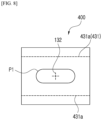
- FIG. 2 is a perspective view schematically illustrating a frostbite prevention pad for a cryolipolysis procedure according to a first exemplary embodiment of the present invention
- FIG. 3 is a view illustrating the frostbite prevention pad for a cryolipolysis procedure illustrated in FIG. 2 when viewed from above.
- FIG. 4 is a view schematically illustrating a state in which the frostbite prevention pad for a cryolipolysis procedure illustrated in FIG. 2 is stretched
- FIG. 5 is a view schematically illustrating a state in which a genuine product identification code is printed on the frostbite prevention pad for a cryolipolysis procedure illustrated in FIG. 2 .
- a frostbite prevention pad 100 for a cryolipolysis procedure is a frostbite prevention pad used for a cryolipolysis procedure using a cryolipolysis device (not illustrated) and includes a base member 110, a waterproof member 120, and one or more sewn parts 130, as illustrated in FIGS. 2 to 5 .
- a cryolipolysis device not illustrated
- FIGS. 2 to 5 the respective constituent elements will be described in detail with reference to FIGS. 2 to 5 .
- the base member 110 is a constituent element configured to come into direct contact with the skin at the treatment area, and the base member 110 may be made of a fiber material in the form of a non-woven fabric.
- an anti-freezing agent in a gel or liquid phase may be easily absorbed into the fiber material of the base member 110.
- the anti-freezing agent absorbed into the base member 110 remains on the skin during the cryolipolysis procedure, thereby preventing the surface of the skin from freezing at a temperature below zero degrees Celsius.
- a cooling plate e.g., a cooling unit of a thermoelectric module
- the base member 110 may prevent the frostbite of the skin and the subcutaneous fat may be cooled while the cold of the cooling plate is transferred to the subcutaneous fat.
- the base member 110 may be made of a material that may be stretched in both a horizontal direction and a vertical direction. Therefore, the base member 110 may be smoothly stretched in all directions while the skin is sucked into the hand piece by negative pressure generated in the hand piece, such that it is possible to prevent the base member 110 from being torn.
- the base member 110 may be made of any one of a fiber assembly and a polymer compound sheet so that the base member 110 may be absorbent and stretched in both the horizontal direction and the vertical direction.
- the fiber assembly may be made of any one or more of natural fibers, chemical fibers, woven fabrics, knitted fabrics, mesh, short fibers, long fibers, and non-woven fabrics.
- the base member 110 may have a greater elongation than the waterproof member 120.
- the waterproof member 120 is a constituent element that prevents the anti-freezing agent absorbed into the base member 110 from being drawn into the cryolipolysis device (not illustrated) through the hand piece (not illustrated).
- the waterproof member 120 may be made of a resin material in the form of a waterproof fabric and may have no vent hole. As illustrated in FIG. 2 , the waterproof member 120 may overlap the base member 110.
- the waterproof member 120 may be made of a material that may be stretched in both the horizontal direction and the vertical direction. Therefore, the waterproof member 120, together with the base member 110, may also be smoothly stretched in all directions while the skin is sucked into the hand piece by the negative pressure generated in the hand piece, such that it is possible to prevent the waterproof member 120 from being torn. If the waterproof member 120 is torn, the anti-freezing agent is drawn into the cryolipolysis device by the hand piece through the torn portion, which may cause a breakdown of the device.
- the base member 110 may be made of any one or more of polyurethane, polyethylene (PE), polypropylene (PP), polyester, polyether ester, polyolefin, polyether, polyethylene terephthalate (PET), polybutylene terephthalate (PBT), polytrimethylene terephthalate (PTT), silicone resin, ethylene-vinyl acetate copolymer (EVA), and polymer synthetic resin so that the base member 110 may be waterproof and stretched in both the horizontal direction and the vertical direction.
- PE polyethylene
- PP polypropylene
- polyester polyester
- polyether ester polyolefin
- polyether polyethylene terephthalate
- PBT polybutylene terephthalate
- PTT polytrimethylene terephthalate
- silicone resin ethylene-vinyl acetate copolymer
- EVA ethylene-vinyl acetate copolymer
- the one or more sewn parts 130 are constituent elements that couple the base member 110 and the waterproof member 120 in the state in which the base member 110 and the waterproof member 120 overlap each other.
- the one or more sewn parts 130 may be formed by sewing the base member 110 and the waterproof member 120 by using a sewing machine or the like.
- a hand-piece contact surface (an outer surface of the waterproof member with which the hand piece comes into contact) of the waterproof member 120 is connected to a skin contact surface (a surface of the base member with which the skin comes into contact) of the base member 110 by the sewing process.
- the present invention provides the technical configuration in which the sewing process is performed in the state in which the base member 110 and the waterproof member 120 overlap each other, and thus the position of the waterproof member 120 does not deviate from the base member 110 during the sewing process. Therefore, unlike the related art, the waterproof member 120 and the base member 110 may be easily and accurately coupled, and thus it is possible to prevent a product defect that may be caused when the waterproof member 120 and the base member 110 are coupled at an undesired position.
- the one or more sewn parts 130 may include edge sewn parts 131 and a center sewn part 132.
- the edge sewn parts 131 may be formed by sewing edges of the waterproof member 120
- the center sewn part 132 may be formed by sewing a central portion of the waterproof member 120.
- the center sewn part 132 serves to fix the position of the central portion of the waterproof member 120 to the base member 110 and also to hold the waterproof member 120 and the base member 110 together so that the waterproof member 120 and the base member 110 are simultaneously sucked into the hand piece when the negative pressure is generated in the hand piece.
- the edge sewn parts 131 may be corner sewn lines 131a by sewing four corners of the waterproof member 120.
- the corner sewn line 131a may have an inclined line shape, both ends of which are disposed at both sides based on the corner of the waterproof member 120. That is, the corner sewn line 131a may define a triangular shape together with outer periphery lines of the corner portion of the waterproof member 120. Therefore, since the sewn line is implemented in the form of the inclined straight line, the corner sewn line 131a may be easily and quickly formed.
- the center sewn part 132 may have a sewn line having a cross shape and formed at the central portion of the waterproof member 120. Therefore, the sewn line is implemented in the form of cross straight lines, the center sewn line may be easily and quickly formed.
- a genuine product identification code 140 may be formed on an outer surface of the waterproof member 120.
- a bar code, a QR code, a serial number, or the like may be used as the genuine product identification code 140.
- the genuine product identification code 140 may be formed within a boundary line of a portion P1 of the waterproof member 120 where the hand piece is positioned. Therefore, in a case in which a detection unit (not illustrated) such as a scanner is mounted on the hand piece and the cryolipolysis device is provided with a controller (not illustrated), the controller determines whether the frostbite prevention pad is the genuine product based on the genuine product identification code 140 detected by the detection unit, and the controller may allow the cryolipolysis device to operate only when the frostbite prevention pad is the genuine product.
- a detection unit such as a scanner
- the cryolipolysis device may allow the cryolipolysis device to operate only when the frostbite prevention pad is the genuine product.
- frostbite prevention pad 200 for a cryolipolysis procedure according to a second exemplary embodiment of the present invention will be described with reference to FIG. 6 .
- FIG. 6 is a view schematically illustrating the frostbite prevention pad for a cryolipolysis procedure according to the second exemplary embodiment of the present invention.
- the frostbite prevention pad 200 for a cryolipolysis procedure according to the second exemplary embodiment of the present invention is identical to the above-mentioned frostbite prevention pad according to the first exemplary embodiment of the present invention except for shapes of corner sewn lines 231, the description will be made below by focusing on the shape of the corner sewn line 231.
- the corner sewn line 231 may have a Korean consonant " " shape, both ends of which are disposed at both sides based on the corner of the waterproof member 120. That is, the corner sewn line 231 may define a quadrangular shape together with outer periphery lines of the corner portion of the waterproof member 120. Therefore, when the corner sewn line 231 is unfolded, the corner sewn line 231 has a longer length than the corner sewn line 131a having the inclined line shape according to the first exemplary embodiment of the present invention, such that it is possible to further improve coupling force.
- frostbite prevention pad 300 for a cryolipolysis procedure according to a third exemplary embodiment of the present invention will be described with reference to FIG. 7 .
- FIG. 7 is a view schematically illustrating the frostbite prevention pad for a cryolipolysis procedure according to the third exemplary embodiment of the present invention.
- the frostbite prevention pad 300 for a cryolipolysis procedure according to the third exemplary embodiment of the present invention is identical to the above-mentioned frostbite prevention pad according to the first exemplary embodiment of the present invention except for shapes of corner sewn lines 331, the description will be made below by focusing on the shape of the corner sewn line 331.
- the corner sewn line 331 may have an arc shape, both ends of which are disposed at both sides based on the corner of the waterproof member 120. That is, the corner sewn line 331 may define a quadrant shape together with outer periphery lines of the corner portion of the waterproof member 120. Therefore, when the corner sewn line 331 is unfolded, the corner sewn line 331 has a longer length than the corner sewn line 131a having the inclined line shape according to the first exemplary embodiment of the present invention, such that it is possible to further improve coupling force. Unlike the above-mentioned corner sewn line 231 having the " " shape according to the second exemplary embodiment of the present invention, there is no portion (notch portion) sharply bent at approximately 90 degrees. Therefore, it is possible to effectively support a load to be applied to the corner sewn line 331.
- frostbite prevention pad 400 for a cryolipolysis procedure according to a fourth exemplary embodiment of the present invention will be described with reference to FIG. 8 .
- FIG. 8 is a view schematically illustrating the frostbite prevention pad for a cryolipolysis procedure according to the fourth exemplary embodiment of the present invention.
- the frostbite prevention pad 400 for a cryolipolysis procedure according to the fourth exemplary embodiment of the present invention is identical to the above-mentioned frostbite prevention pad according to the first exemplary embodiment of the present invention except for positions and shapes of edge sewn parts 431, the description will be made below by focusing on the position and the shape of the edge sewn part 431.
- the edge sewn parts 431 may be long side sewn lines 431a formed at two relatively long sides of the waterproof member 120 and elongated in a longitudinal direction by a sewing process. Therefore, in comparison with the above-mentioned four corner sewn lines 131a according to the first exemplary embodiment of the present invention, the number of sewn lines is reduced to two, such that the long side sewn lines 431a may be easily and quickly formed.
- the long side sewn line 431a has a much longer length than the corner sewn line 131a having the above-mentioned inclined line shape according to the first exemplary embodiment of the present invention, such that it is possible to further improve coupling force.
- frostbite prevention pad 500 for a cryolipolysis procedure according to a fifth exemplary embodiment of the present invention will be described with reference to FIG. 9 .
- FIG. 9 is a view schematically illustrating the frostbite prevention pad for a cryolipolysis procedure according to the fifth exemplary embodiment of the present invention.
- the frostbite prevention pad 500 for a cryolipolysis procedure according to the fifth exemplary embodiment of the present invention is identical to the above-mentioned frostbite prevention pad according to the first exemplary embodiment of the present invention except for shapes of center sewn parts 532, the description will be made below by focusing on the shape of the center sewn part 532.
- the center sewn part 532 may have a quadrangular sewn line formed at the central portion of the waterproof member 120. Therefore, when the sewn line 532 is unfolded, the sewn line 532 has a longer overall length than the above-mentioned sewn line 132 having the cross shape according to the first exemplary embodiment of the present invention, such that it is possible to further improve coupling force.
- frostbite prevention pad 600 for a cryolipolysis procedure according to a sixth exemplary embodiment of the present invention will be described with reference to FIG. 10 .
- FIG. 10 is a view schematically illustrating the frostbite prevention pad for a cryolipolysis procedure according to the sixth exemplary embodiment of the present invention.
- the center sewn part 632 may have a circular sewn line formed at the central portion of the waterproof member 120. Therefore, when the sewn line 632 is unfolded, the sewn line 632 has a longer overall length than the above-mentioned sewn line 132 having the cross shape according to the first exemplary embodiment of the present invention, such that it is possible to further improve coupling force. Unlike the above-mentioned quadrangular sewn line 532 according to the fifth exemplary embodiment of the present invention, there is no portion (notch portion) sharply bent at approximately 90 degrees. Therefore, it is possible to effectively support a load to be applied to the sewn line.
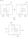
- frostbite prevention pad 700 for a cryolipolysis procedure according to a seventh exemplary embodiment of the present invention will be described with reference to FIGS. 11 and 12 .
- FIG. 11 is a perspective view schematically illustrating the frostbite prevention pad for a cryolipolysis procedure according to the seventh exemplary embodiment of the present invention
- FIG. 12 is a view schematically illustrating a process in which first and second waterproof pads of the frostbite prevention pad for a cryolipolysis procedure illustrated in FIG. 11 overlap each other.
- the frostbite prevention pad 700 for a cryolipolysis procedure according to the seventh exemplary embodiment of the present invention is identical to the above-mentioned frostbite prevention pad according to the first exemplary embodiment of the present invention except that one or more waterproof members 720 include first and second waterproof members 721 and 722, the description will be made below by focusing on this configuration.
- the one or more waterproof members 720 may include the first and second waterproof members 721 and 722.
- the first waterproof member 721 may be placed to overlap the base member 110 and made of a waterproof and stretchable resin material
- the second waterproof member 722 may be placed to overlap the first waterproof member 721 and made of a waterproof and stretchable resin material identical to the material of the first waterproof member 721.
- the first and second waterproof members 721 and 722 may be made of a material identical to the material of the above-mentioned waterproof member 120 according to the first exemplary embodiment of the present invention.
- the one or more sewn parts 130 may be formed by sewing the base member 110, the first waterproof member 721, and the second waterproof member 722 to combine the base member 110, the first waterproof member 721, and the second waterproof member 722 in a state in which the base member 110, the first waterproof member 721, and the second waterproof member 722 overlap one another.
- first vent holes 721a may be formed in the first waterproof member 721, and second vent holes 722a may be formed in the second waterproof member 722.
- first and second vent holes 721a and 722a may serve as passageways through which the negative pressure generated in the hand piece (not illustrated) is transmitted to the skin.
- first and second vent holes 721a and 722a may be disposed so as not to overlap one another so that the anti-freezing agent absorbed into the base member 110 is not drawn into the hand piece (not illustrated) through the first and second vent holes 721a and 722a.
- position setting parts 750 may be formed on the first and second waterproof members 721 and 722 so that the first vent hole 721a and the second vent hole 722a do not overlap each other.
- the position setting parts 750 may include a first position identification line 751 formed on the first waterproof member 721 and disposed at one side based on a centerline of the first waterproof member 721, and a second position identification line 752 formed on the second waterproof member 722 and disposed at the other side based on the centerline of the first waterproof member 721. Therefore, the first and second vent holes 721a and 722a may be prevented from overlapping one another when the first and second waterproof members 721 and 722 overlap each other to connect the first position identification line 751 and the second position identification line 752.
- first and second position identification lines 751 and 752 when the first and second position identification lines 751 and 752 are connected to each other, the first and second position identification lines 751 and 752 may also define a portion P2 where the hand piece (not illustrated) of the cryolipolysis device is positioned.
- the present invention relates to a pad for preventing frostbite during a cryolipolysis procedure and is applicable to a cryolipolysis device.
Landscapes
- Health & Medical Sciences (AREA)
- Surgery (AREA)
- Life Sciences & Earth Sciences (AREA)
- Nuclear Medicine, Radiotherapy & Molecular Imaging (AREA)
- Animal Behavior & Ethology (AREA)
- Veterinary Medicine (AREA)
- Public Health (AREA)
- Engineering & Computer Science (AREA)
- Biomedical Technology (AREA)
- Heart & Thoracic Surgery (AREA)
- General Health & Medical Sciences (AREA)
- Molecular Biology (AREA)
- Medical Informatics (AREA)
- Pathology (AREA)
- Oral & Maxillofacial Surgery (AREA)
- Otolaryngology (AREA)
- Vascular Medicine (AREA)
- Physics & Mathematics (AREA)
- Thermal Sciences (AREA)
- Thermotherapy And Cooling Therapy Devices (AREA)
- Professional, Industrial, Or Sporting Protective Garments (AREA)
- Surgical Instruments (AREA)
- Sewing Machines And Sewing (AREA)
Claims (15)
- Erfrierungsschutzpolster (100) für eine Krylipolysebehandlung, das für eine Krylipolysebehandlung unter Verwendung einer Kryolipolysevorrichtung verwendet wird, wobei das Erfrierungsschutzpolster (100) Folgendes umfasst:ein Basiselement (110) bestehend aus einem Fasermaterial;ein oder mehrere wasserdichte Elemente (120), die aus einem Harzmaterial bestehen und so platziert sind, dass sie das Basiselement (110) überlappen;
dadurch gekennzeichnet, dassein oder mehrere genähte Teile (130), die durch Nähen des Basiselements und des wasserdichten Elements (120) ausgebildet sind, um das Basiselement (110) und das wasserdichte Element (120) in einem Zustand zu koppeln, in dem das Basiselement (110) und das wasserdichte Element (120) einander überlappen,wobei, während ein Unterdruck durch die Kryolipolysevorrichtung erzeugt wird, um zu verhindern, dass das wasserdichte Element (120) reißt, oder um zu verhindern, dass das wasserdichte Element (120) und das Basiselement (110) voneinander getrennt werden, das eine oder die mehreren genähten Teile (130) an den Kanten genähte Teile (131), die durch Nähen von Kanten des wasserdichten Elements (120) ausgebildet sind, und ein mittleres genähtes Teil (132) umfassen, das durch Nähen eines zentralen Bereichs des wasserdichten Elements (120) ausgebildet ist. - Erfrierungsschutzpolster (100) gemäß Anspruch 1, wobei die an den Kanten genähten Teile (131) an den Ecken genähte Linien (131a) umfassen, die durch Nähen von vier Ecken des wasserdichten Elements (120) ausgebildet sind.
- Erfrierungsschutzpolster (100) gemäß Anspruch 2, wobei die an den Ecken genähte Linie (131a) eine schräge Linienform aufweist und beide Enden der an den Ecken genähten Linie (131a) an beiden Seiten basierend auf der Ecke des wasserdichten Elements (120) angeordnet sind.
- Erfrierungsschutzpolster (100) gemäß Anspruch 2, wobei die an den Ecken genähte Linie (131a) eine Form des koreanischen Konsonanten "" aufweist und beide Enden der an den Ecken genähten Linie (131a) an beiden Seiten basierend auf der Ecke des wasserdichten Elements (120) angeordnet sind und/oder wobei die an den Ecken genähte Linie (131a) eine Bogenform aufweist und beide Enden der an den Ecken genähten Linie (131a) an beiden Seiten basierend auf der Ecke des wasserdichten Elements (120) angeordnet sind.

- Erfrierungsschutzpolster (100) gemäß Anspruch 1, wobei die an der Kante genähten Teile (131) lange an den Seiten genähte Linien (431a) umfassen, die an zwei relativ langen Seiten des wasserdichten Elements (120) ausgebildet sind und durch einen Nähvorgang in einer Längsrichtung verlängert sind.
- Erfrierungsschutzpolster (100) gemäß Anspruch 1, wobei der mittlere genähte Teil (132) eine genähte Linie (131a) mit einer Kreuzform an dem zentralen Bereich des wasserdichten Elements (120) aufweist und/oder wobei der mittlere genähte Teil (132) eine viereckige genähte Linie (532) an dem zentralen Bereich des wasserdichten Elements (120) aufweist und/oder wobei der mittlere genähte Teil (132) eine kreisförmige genähte Linie an dem zentralen Bereich des wasserdichten Elements (120) aufweist.
- Erfrierungsschutzpolster (100) gemäß Anspruch 1, wobei jedes des Basiselements (110) und des wasserdichten Elements (120) sowohl in einer horizontalen Richtung als auch in einer vertikalen Richtung dehnbar ist, und wobei insbesondere das Basiselement (110) ein größeres Dehnungsverhältnis als das wasserdichte Element (120) aufweist.
- Erfrierungsschutzpolster (100) gemäß Anspruch 1, wobei das Basiselement (110) mit einem Gefrierschutzmittel imprägniert ist.
- Erfrierungsschutzpolster (100) gemäß Anspruch 1, wobei ein Originalprodukt-Identifikationscode (140) auf einer äußeren Oberfläche des wasserdichten Elements (120) ausgebildet ist.
- Erfrierungsschutzpolster (100) gemäß Anspruch 9, wobei der Originalprodukt-Identifikationscode (140) an einem Bereich des wasserdichten Elements (120) ausgebildet ist, an dem ein Handstück der Kryolipolysevorrichtung positioniert ist, und der Originalprodukt-Identifikationscode (140) von einer Erfassungseinheit erfasst wird, die an dem Handstück vorgesehen ist.
- Erfrierungsschutzpolster (100) gemäß Anspruch 1, wobei das eine oder die mehreren wasserdichten Elemente (120) Folgendes umfassen:ein erstes wasserdichtes Element (120), das so platziert ist, dass es das Basiselement (110) überlappt und aus einem Harzmaterial besteht; undein zweites wasserdichtes Element (120), das so platziert ist, dass es das erste wasserdichte Element (120) überlappt und aus einem Harzmaterial besteht, unddie ein oder mehreren genähten Teile (130) durch Nähen des Basiselements (110), des ersten wasserdichten Elements (120) und des zweiten wasserdichten Elements (120) ausgebildet sind, um das Basiselement (110), das erste wasserdichte Element (120) und das zweite wasserdichte Element (120) in einem Zustand zu kombinieren, in dem das Basiselement (110), das erste wasserdichte Element (120) und das zweite wasserdichte Element (120) einander überlappen.
- Erfrierungsschutzpolster (100) gemäß Anspruch 11, wobei ein erstes Entlüftungsloch in dem ersten wasserdichten Element (120) ausgebildet ist und ein zweites Entlüftungsloch in dem zweiten wasserdichten Element (120) so ausgebildet ist, dass es das erste Entlüftungsloch nicht überlappt.
- Erfrierungsschutzpolster (100) gemäß Anspruch 12, wobei Positionseinstellteile an den ersten und zweiten wasserdichten Elementen (120) so ausgebildet sind, dass das erste Entlüftungsloch und das zweite Entlüftungsloch einander nicht überlappen.
- Erfrierungsschutzpolster (100) gemäß Anspruch 13, wobei die Positionseinstellteile Folgendes umfassen:eine erste Positionsidentifikationslinie, die auf dem ersten wasserdichten Element (120) ausgebildet ist und an einer Seite basierend auf einer Mittellinie des ersten wasserdichten Elements (120) angeordnet ist; undeine zweite Positionsidentifikationslinie, die auf dem zweiten wasserdichten Element (120) ausgebildet und auf der anderen Seite basierend auf der Mittellinie des ersten wasserdichten Elements (120) angeordnet ist, unddie ersten und zweiten Entlüftungslöcher daran gehindert werden, sich gegenseitig zu überlappen, wenn die ersten und zweiten wasserdichten Elemente (120) sich gegenseitig überlappen, so dass die erste Positionsidentifikationslinie und die zweite Positionsidentifikationslinie miteinander verbunden sind.
- Erfrierungsschutzpolster (100) gemäß Anspruch 14, wobei die erste und die zweite Positionsidentifikationslinie miteinander verbunden sind und einen Bereich definieren, in dem ein Handstück der Kryolipolysevorrichtung positioniert ist.
Applications Claiming Priority (2)
| Application Number | Priority Date | Filing Date | Title |
|---|---|---|---|
| KR1020170116512A KR102040913B1 (ko) | 2017-09-12 | 2017-09-12 | 냉각 지방 분해 시술용 동상 방지 패드 |
| PCT/KR2018/010548 WO2019054706A1 (ko) | 2017-09-12 | 2018-09-10 | 냉각 지방 분해 시술용 동상 방지 패드 |
Publications (4)
| Publication Number | Publication Date |
|---|---|
| EP3682829A1 EP3682829A1 (de) | 2020-07-22 |
| EP3682829A4 EP3682829A4 (de) | 2021-06-09 |
| EP3682829B1 true EP3682829B1 (de) | 2025-04-02 |
| EP3682829C0 EP3682829C0 (de) | 2025-04-02 |
Family
ID=65722962
Family Applications (1)
| Application Number | Title | Priority Date | Filing Date |
|---|---|---|---|
| EP18855370.5A Active EP3682829B1 (de) | 2017-09-12 | 2018-09-10 | Frostverhinderungs-pad für kryolipolyseverfahren |
Country Status (8)
| Country | Link |
|---|---|
| US (1) | US11759353B2 (de) |
| EP (1) | EP3682829B1 (de) |
| JP (1) | JP6984005B2 (de) |
| KR (1) | KR102040913B1 (de) |
| CN (1) | CN111065347B (de) |
| AU (1) | AU2018332432B2 (de) |
| RU (1) | RU2744206C1 (de) |
| WO (1) | WO2019054706A1 (de) |
Families Citing this family (1)
| Publication number | Priority date | Publication date | Assignee | Title |
|---|---|---|---|---|
| EP3906901A1 (de) * | 2020-05-04 | 2021-11-10 | High Technology Products, SL | Pads, und systeme zur behandlung einer person |
Family Cites Families (20)
| Publication number | Priority date | Publication date | Assignee | Title |
|---|---|---|---|---|
| JPH07216727A (ja) * | 1994-01-27 | 1995-08-15 | Teijin Ltd | 防水布帛 |
| JP4086401B2 (ja) * | 1999-02-10 | 2008-05-14 | 株式会社クラレ | 防水性手袋およびその製造方法 |
| US6786880B2 (en) * | 1999-08-06 | 2004-09-07 | Lisa Wall | Therapeutic pad |
| US6638605B1 (en) * | 1999-11-16 | 2003-10-28 | Allegiance Corporation | Intermittently bonded nonwoven disposable surgical laminates |
| JP4134052B2 (ja) * | 2005-01-19 | 2008-08-13 | 株式会社 ハリーズ | 生理用タンポンの製造方法及び製造装置 |
| US20060224136A1 (en) * | 2005-03-31 | 2006-10-05 | Martinez Christina M G | Cloth menstrual pad with hemp core |
| KR100694187B1 (ko) * | 2005-08-10 | 2007-03-14 | 이종석 | 흡습성 패드 |
| JP4394160B1 (ja) * | 2009-04-15 | 2010-01-06 | 石崎資材株式会社 | 吸水パッド |
| CN204863452U (zh) * | 2013-05-09 | 2015-12-16 | 海罗尼克株式会社 | 脂肪分解装置 |
| KR101487850B1 (ko) * | 2013-08-08 | 2015-02-02 | (주)클래시스 | 냉각을 이용한 비만치료 장치 |
| CN103405311A (zh) * | 2013-08-26 | 2013-11-27 | 张家港市翔达纺织有限公司 | 灭菌透气纸尿片 |
| RU2576830C2 (ru) | 2013-09-10 | 2016-03-10 | Общество с ограниченной ответственностью "Ликели" | Биологически активные производные аллоферона-1 |
| KR101563287B1 (ko) * | 2013-10-23 | 2015-10-27 | 주식회사 하이로닉 | 지방 분해 장치 |
| WO2015117032A1 (en) | 2014-01-31 | 2015-08-06 | Zeltiq Aesthestic, Inc. | Treatment systems for treating glands by cooling |
| KR200481035Y1 (ko) | 2014-09-23 | 2016-08-04 | 박병권 | 동상 방지용 패드 구조 |
| KR20160080294A (ko) * | 2014-12-26 | 2016-07-08 | 주식회사 하이로닉 | 시술 보조제가 적용된 패치, 이를 포함하는 시술 시스템 및 시술 방법 |
| KR101641162B1 (ko) * | 2015-04-23 | 2016-07-20 | 제이씨스퀘어주식회사 | Nfc 기반 정품 인증 등록 시스템 및 방법 |
| CN104758123A (zh) * | 2015-04-28 | 2015-07-08 | 彭艳燕 | 智能卫生巾、护垫 |
| KR101693763B1 (ko) * | 2016-04-12 | 2017-01-06 | 정성재 | 냉각 지방 분해 시술용 동상 방지 패드 및 이의 제조 방법 |
| CN106042538B (zh) * | 2016-07-22 | 2019-03-26 | 东丽酒伊织染(南通)有限公司 | 一种蓄热防水透湿户外羽绒防寒服面料及其制备方法 |
-
2017
- 2017-09-12 KR KR1020170116512A patent/KR102040913B1/ko active Active
-
2018
- 2018-09-10 JP JP2020514165A patent/JP6984005B2/ja active Active
- 2018-09-10 CN CN201880058744.5A patent/CN111065347B/zh active Active
- 2018-09-10 US US16/645,256 patent/US11759353B2/en active Active
- 2018-09-10 AU AU2018332432A patent/AU2018332432B2/en not_active Ceased
- 2018-09-10 RU RU2020112477A patent/RU2744206C1/ru active
- 2018-09-10 WO PCT/KR2018/010548 patent/WO2019054706A1/ko not_active Ceased
- 2018-09-10 EP EP18855370.5A patent/EP3682829B1/de active Active
Also Published As
| Publication number | Publication date |
|---|---|
| CN111065347A (zh) | 2020-04-24 |
| BR112020004850A2 (pt) | 2020-09-15 |
| AU2018332432A1 (en) | 2020-03-26 |
| EP3682829A1 (de) | 2020-07-22 |
| KR20190029214A (ko) | 2019-03-20 |
| AU2018332432B2 (en) | 2021-11-04 |
| JP6984005B2 (ja) | 2021-12-17 |
| EP3682829C0 (de) | 2025-04-02 |
| JP2020533092A (ja) | 2020-11-19 |
| WO2019054706A1 (ko) | 2019-03-21 |
| US11759353B2 (en) | 2023-09-19 |
| KR102040913B1 (ko) | 2019-11-05 |
| EP3682829A4 (de) | 2021-06-09 |
| CN111065347B (zh) | 2023-04-21 |
| US20200214881A1 (en) | 2020-07-09 |
| RU2744206C1 (ru) | 2021-03-03 |
Similar Documents
| Publication | Publication Date | Title |
|---|---|---|
| CN102438681B (zh) | 具有集成敷料的稳定装置 | |
| KR102489988B1 (ko) | 의료 용품 고정 시스템 | |
| EP2879634B1 (de) | Integrierte heftpflasterverpackung | |
| US9327098B2 (en) | Fixation device | |
| EP2545954B1 (de) | Katheterfixierungsvorrichtung | |
| US20100121282A1 (en) | Reinforced closure anchor | |
| US20130110048A1 (en) | Patient site protective cover | |
| CN105286935B (zh) | 一种伤口缝合拉扣 | |
| JP2020512894A (ja) | 窓付きカテーテル固定装置 | |
| EP3682829B1 (de) | Frostverhinderungs-pad für kryolipolyseverfahren | |
| US20200360216A1 (en) | Article of manufacture, patient pad system and method for a surgical procedure | |
| JP5918777B2 (ja) | カテーテル固定用貼付材 | |
| KR20160003075U (ko) | 카테터 고정용 접착밴드 | |
| KR101446763B1 (ko) | 팔고정장치 | |
| CN222708391U (zh) | 一种袖装式介入手术无菌手术大单 | |
| US10758671B2 (en) | Securement device assembly and securement and dressing device assembly and method of applying said device assemblies | |
| JP2010063547A (ja) | 鍼治療用指先感染防止シート | |
| BR112020004850B1 (pt) | Almofada para prevenção de ulceração por congelamento no procedimento de criolipólise | |
| US20170281289A1 (en) | Femoral drape | |
| US10575914B1 (en) | Surgical drape | |
| WO2016147014A1 (en) | Clothing protector | |
| JP2004321781A (ja) | 保護フィルム付防水シーツ | |
| JP3101774U (ja) | 中敷体付手袋及びその中敷体 | |
| US20200139100A1 (en) | Medical port locator | |
| CN210813371U (zh) | 一种导尿管体外固定装置 |
Legal Events
| Date | Code | Title | Description |
|---|---|---|---|
| STAA | Information on the status of an ep patent application or granted ep patent |
Free format text: STATUS: THE INTERNATIONAL PUBLICATION HAS BEEN MADE |
|
| PUAI | Public reference made under article 153(3) epc to a published international application that has entered the european phase |
Free format text: ORIGINAL CODE: 0009012 |
|
| STAA | Information on the status of an ep patent application or granted ep patent |
Free format text: STATUS: REQUEST FOR EXAMINATION WAS MADE |
|
| 17P | Request for examination filed |
Effective date: 20200312 |
|
| AK | Designated contracting states |
Kind code of ref document: A1 Designated state(s): AL AT BE BG CH CY CZ DE DK EE ES FI FR GB GR HR HU IE IS IT LI LT LU LV MC MK MT NL NO PL PT RO RS SE SI SK SM TR |
|
| AX | Request for extension of the european patent |
Extension state: BA ME |
|
| DAV | Request for validation of the european patent (deleted) | ||
| DAX | Request for extension of the european patent (deleted) | ||
| A4 | Supplementary search report drawn up and despatched |
Effective date: 20210511 |
|
| RIC1 | Information provided on ipc code assigned before grant |
Ipc: A61B 18/02 20060101AFI20210504BHEP Ipc: A61F 7/00 20060101ALI20210504BHEP Ipc: A61B 90/90 20160101ALI20210504BHEP Ipc: A61F 7/02 20060101ALI20210504BHEP Ipc: A61B 18/00 20060101ALI20210504BHEP Ipc: A61B 90/94 20160101ALI20210504BHEP Ipc: A61B 90/00 20160101ALI20210504BHEP |
|
| GRAP | Despatch of communication of intention to grant a patent |
Free format text: ORIGINAL CODE: EPIDOSNIGR1 |
|
| STAA | Information on the status of an ep patent application or granted ep patent |
Free format text: STATUS: GRANT OF PATENT IS INTENDED |
|
| INTG | Intention to grant announced |
Effective date: 20241030 |
|
| GRAS | Grant fee paid |
Free format text: ORIGINAL CODE: EPIDOSNIGR3 |
|
| GRAA | (expected) grant |
Free format text: ORIGINAL CODE: 0009210 |
|
| STAA | Information on the status of an ep patent application or granted ep patent |
Free format text: STATUS: THE PATENT HAS BEEN GRANTED |
|
| AK | Designated contracting states |
Kind code of ref document: B1 Designated state(s): AL AT BE BG CH CY CZ DE DK EE ES FI FR GB GR HR HU IE IS IT LI LT LU LV MC MK MT NL NO PL PT RO RS SE SI SK SM TR |
|
| REG | Reference to a national code |
Ref country code: GB Ref legal event code: FG4D |
|
| REG | Reference to a national code |
Ref country code: CH Ref legal event code: EP |
|
| REG | Reference to a national code |
Ref country code: IE Ref legal event code: FG4D |
|
| REG | Reference to a national code |
Ref country code: DE Ref legal event code: R096 Ref document number: 602018080796 Country of ref document: DE |
|
| U01 | Request for unitary effect filed |
Effective date: 20250403 |
|
| U07 | Unitary effect registered |
Designated state(s): AT BE BG DE DK EE FI FR IT LT LU LV MT NL PT RO SE SI Effective date: 20250409 |
|
| U20 | Renewal fee for the european patent with unitary effect paid |
Year of fee payment: 8 Effective date: 20250902 |
|
| PG25 | Lapsed in a contracting state [announced via postgrant information from national office to epo] |
Ref country code: ES Free format text: LAPSE BECAUSE OF FAILURE TO SUBMIT A TRANSLATION OF THE DESCRIPTION OR TO PAY THE FEE WITHIN THE PRESCRIBED TIME-LIMIT Effective date: 20250402 |
|
| PG25 | Lapsed in a contracting state [announced via postgrant information from national office to epo] |
Ref country code: GR Free format text: LAPSE BECAUSE OF FAILURE TO SUBMIT A TRANSLATION OF THE DESCRIPTION OR TO PAY THE FEE WITHIN THE PRESCRIBED TIME-LIMIT Effective date: 20250703 Ref country code: NO Free format text: LAPSE BECAUSE OF FAILURE TO SUBMIT A TRANSLATION OF THE DESCRIPTION OR TO PAY THE FEE WITHIN THE PRESCRIBED TIME-LIMIT Effective date: 20250702 |
|
| PG25 | Lapsed in a contracting state [announced via postgrant information from national office to epo] |
Ref country code: PL Free format text: LAPSE BECAUSE OF FAILURE TO SUBMIT A TRANSLATION OF THE DESCRIPTION OR TO PAY THE FEE WITHIN THE PRESCRIBED TIME-LIMIT Effective date: 20250402 |
|
| PG25 | Lapsed in a contracting state [announced via postgrant information from national office to epo] |
Ref country code: HR Free format text: LAPSE BECAUSE OF FAILURE TO SUBMIT A TRANSLATION OF THE DESCRIPTION OR TO PAY THE FEE WITHIN THE PRESCRIBED TIME-LIMIT Effective date: 20250402 |
|
| PG25 | Lapsed in a contracting state [announced via postgrant information from national office to epo] |
Ref country code: RS Free format text: LAPSE BECAUSE OF FAILURE TO SUBMIT A TRANSLATION OF THE DESCRIPTION OR TO PAY THE FEE WITHIN THE PRESCRIBED TIME-LIMIT Effective date: 20250702 |
|
| PG25 | Lapsed in a contracting state [announced via postgrant information from national office to epo] |
Ref country code: IS Free format text: LAPSE BECAUSE OF FAILURE TO SUBMIT A TRANSLATION OF THE DESCRIPTION OR TO PAY THE FEE WITHIN THE PRESCRIBED TIME-LIMIT Effective date: 20250802 |
|
| PG25 | Lapsed in a contracting state [announced via postgrant information from national office to epo] |
Ref country code: SM Free format text: LAPSE BECAUSE OF FAILURE TO SUBMIT A TRANSLATION OF THE DESCRIPTION OR TO PAY THE FEE WITHIN THE PRESCRIBED TIME-LIMIT Effective date: 20250402 |
|
| PG25 | Lapsed in a contracting state [announced via postgrant information from national office to epo] |
Ref country code: CZ Free format text: LAPSE BECAUSE OF FAILURE TO SUBMIT A TRANSLATION OF THE DESCRIPTION OR TO PAY THE FEE WITHIN THE PRESCRIBED TIME-LIMIT Effective date: 20250402 |
|
| PG25 | Lapsed in a contracting state [announced via postgrant information from national office to epo] |
Ref country code: SK Free format text: LAPSE BECAUSE OF FAILURE TO SUBMIT A TRANSLATION OF THE DESCRIPTION OR TO PAY THE FEE WITHIN THE PRESCRIBED TIME-LIMIT Effective date: 20250402 |
|
| PLBE | No opposition filed within time limit |
Free format text: ORIGINAL CODE: 0009261 |
|
| STAA | Information on the status of an ep patent application or granted ep patent |
Free format text: STATUS: NO OPPOSITION FILED WITHIN TIME LIMIT |
|
| REG | Reference to a national code |
Ref country code: CH Ref legal event code: L10 Free format text: ST27 STATUS EVENT CODE: U-0-0-L10-L00 (AS PROVIDED BY THE NATIONAL OFFICE) Effective date: 20260211 |