EP3682099B1 - Internal combustion engine and method for controlling such an internal combustion engine - Google Patents
Internal combustion engine and method for controlling such an internal combustion engine Download PDFInfo
- Publication number
- EP3682099B1 EP3682099B1 EP18852910.1A EP18852910A EP3682099B1 EP 3682099 B1 EP3682099 B1 EP 3682099B1 EP 18852910 A EP18852910 A EP 18852910A EP 3682099 B1 EP3682099 B1 EP 3682099B1
- Authority
- EP
- European Patent Office
- Prior art keywords
- cad
- exhaust
- intake port
- range
- port
- Prior art date
- Legal status (The legal status is an assumption and is not a legal conclusion. Google has not performed a legal analysis and makes no representation as to the accuracy of the status listed.)
- Active
Links
Images
Classifications
-
- F—MECHANICAL ENGINEERING; LIGHTING; HEATING; WEAPONS; BLASTING
- F02—COMBUSTION ENGINES; HOT-GAS OR COMBUSTION-PRODUCT ENGINE PLANTS
- F02D—CONTROLLING COMBUSTION ENGINES
- F02D41/00—Electrical control of supply of combustible mixture or its constituents
- F02D41/02—Circuit arrangements for generating control signals
- F02D41/021—Introducing corrections for particular conditions exterior to the engine
- F02D41/0235—Introducing corrections for particular conditions exterior to the engine in relation with the state of the exhaust gas treating apparatus
- F02D41/024—Introducing corrections for particular conditions exterior to the engine in relation with the state of the exhaust gas treating apparatus to increase temperature of the exhaust gas treating apparatus
-
- F—MECHANICAL ENGINEERING; LIGHTING; HEATING; WEAPONS; BLASTING
- F02—COMBUSTION ENGINES; HOT-GAS OR COMBUSTION-PRODUCT ENGINE PLANTS
- F02D—CONTROLLING COMBUSTION ENGINES
- F02D13/00—Controlling the engine output power by varying inlet or exhaust valve operating characteristics, e.g. timing
- F02D13/02—Controlling the engine output power by varying inlet or exhaust valve operating characteristics, e.g. timing during engine operation
- F02D13/0261—Controlling the valve overlap
-
- F—MECHANICAL ENGINEERING; LIGHTING; HEATING; WEAPONS; BLASTING
- F02—COMBUSTION ENGINES; HOT-GAS OR COMBUSTION-PRODUCT ENGINE PLANTS
- F02B—INTERNAL-COMBUSTION PISTON ENGINES; COMBUSTION ENGINES IN GENERAL
- F02B37/00—Engines characterised by provision of pumps driven at least for part of the time by exhaust
- F02B37/12—Control of the pumps
- F02B37/18—Control of the pumps by bypassing exhaust from the inlet to the outlet of turbine or to the atmosphere
-
- F—MECHANICAL ENGINEERING; LIGHTING; HEATING; WEAPONS; BLASTING
- F02—COMBUSTION ENGINES; HOT-GAS OR COMBUSTION-PRODUCT ENGINE PLANTS
- F02B—INTERNAL-COMBUSTION PISTON ENGINES; COMBUSTION ENGINES IN GENERAL
- F02B75/00—Other engines
- F02B75/02—Engines characterised by their cycles, e.g. six-stroke
-
- F—MECHANICAL ENGINEERING; LIGHTING; HEATING; WEAPONS; BLASTING
- F02—COMBUSTION ENGINES; HOT-GAS OR COMBUSTION-PRODUCT ENGINE PLANTS
- F02D—CONTROLLING COMBUSTION ENGINES
- F02D13/00—Controlling the engine output power by varying inlet or exhaust valve operating characteristics, e.g. timing
- F02D13/02—Controlling the engine output power by varying inlet or exhaust valve operating characteristics, e.g. timing during engine operation
-
- F—MECHANICAL ENGINEERING; LIGHTING; HEATING; WEAPONS; BLASTING
- F02—COMBUSTION ENGINES; HOT-GAS OR COMBUSTION-PRODUCT ENGINE PLANTS
- F02D—CONTROLLING COMBUSTION ENGINES
- F02D13/00—Controlling the engine output power by varying inlet or exhaust valve operating characteristics, e.g. timing
- F02D13/02—Controlling the engine output power by varying inlet or exhaust valve operating characteristics, e.g. timing during engine operation
- F02D13/0203—Variable control of intake and exhaust valves
- F02D13/0215—Variable control of intake and exhaust valves changing the valve timing only
-
- F—MECHANICAL ENGINEERING; LIGHTING; HEATING; WEAPONS; BLASTING
- F02—COMBUSTION ENGINES; HOT-GAS OR COMBUSTION-PRODUCT ENGINE PLANTS
- F02D—CONTROLLING COMBUSTION ENGINES
- F02D13/00—Controlling the engine output power by varying inlet or exhaust valve operating characteristics, e.g. timing
- F02D13/02—Controlling the engine output power by varying inlet or exhaust valve operating characteristics, e.g. timing during engine operation
- F02D13/0203—Variable control of intake and exhaust valves
- F02D13/0215—Variable control of intake and exhaust valves changing the valve timing only
- F02D13/0219—Variable control of intake and exhaust valves changing the valve timing only by shifting the phase, i.e. the opening periods of the valves are constant
-
- F—MECHANICAL ENGINEERING; LIGHTING; HEATING; WEAPONS; BLASTING
- F02—COMBUSTION ENGINES; HOT-GAS OR COMBUSTION-PRODUCT ENGINE PLANTS
- F02D—CONTROLLING COMBUSTION ENGINES
- F02D41/00—Electrical control of supply of combustible mixture or its constituents
- F02D41/0002—Controlling intake air
-
- F—MECHANICAL ENGINEERING; LIGHTING; HEATING; WEAPONS; BLASTING
- F02—COMBUSTION ENGINES; HOT-GAS OR COMBUSTION-PRODUCT ENGINE PLANTS
- F02D—CONTROLLING COMBUSTION ENGINES
- F02D41/00—Electrical control of supply of combustible mixture or its constituents
- F02D41/0025—Controlling engines characterised by use of non-liquid fuels, pluralities of fuels, or non-fuel substances added to the combustible mixtures
- F02D41/003—Adding fuel vapours, e.g. drawn from engine fuel reservoir
- F02D41/0032—Controlling the purging of the canister as a function of the engine operating conditions
- F02D41/0035—Controlling the purging of the canister as a function of the engine operating conditions to achieve a special effect, e.g. to warm up the catalyst
-
- F—MECHANICAL ENGINEERING; LIGHTING; HEATING; WEAPONS; BLASTING
- F02—COMBUSTION ENGINES; HOT-GAS OR COMBUSTION-PRODUCT ENGINE PLANTS
- F02D—CONTROLLING COMBUSTION ENGINES
- F02D41/00—Electrical control of supply of combustible mixture or its constituents
- F02D41/02—Circuit arrangements for generating control signals
- F02D41/04—Introducing corrections for particular operating conditions
- F02D41/06—Introducing corrections for particular operating conditions for engine starting or warming up
- F02D41/062—Introducing corrections for particular operating conditions for engine starting or warming up for starting
- F02D41/064—Introducing corrections for particular operating conditions for engine starting or warming up for starting at cold start
-
- F—MECHANICAL ENGINEERING; LIGHTING; HEATING; WEAPONS; BLASTING
- F02—COMBUSTION ENGINES; HOT-GAS OR COMBUSTION-PRODUCT ENGINE PLANTS
- F02D—CONTROLLING COMBUSTION ENGINES
- F02D41/00—Electrical control of supply of combustible mixture or its constituents
- F02D41/30—Controlling fuel injection
- F02D41/32—Controlling fuel injection of the low pressure type
- F02D41/34—Controlling fuel injection of the low pressure type with means for controlling injection timing or duration
- F02D41/345—Controlling injection timing
-
- F—MECHANICAL ENGINEERING; LIGHTING; HEATING; WEAPONS; BLASTING
- F02—COMBUSTION ENGINES; HOT-GAS OR COMBUSTION-PRODUCT ENGINE PLANTS
- F02M—SUPPLYING COMBUSTION ENGINES IN GENERAL WITH COMBUSTIBLE MIXTURES OR CONSTITUENTS THEREOF
- F02M35/00—Combustion-air cleaners, air intakes, intake silencers, or induction systems specially adapted for, or arranged on, internal-combustion engines
- F02M35/10—Air intakes; Induction systems
- F02M35/10209—Fluid connections to the air intake system; their arrangement of pipes, valves or the like
- F02M35/10222—Exhaust gas recirculation [EGR]; Positive crankcase ventilation [PCV]; Additional air admission, lubricant or fuel vapour admission
-
- F—MECHANICAL ENGINEERING; LIGHTING; HEATING; WEAPONS; BLASTING
- F02—COMBUSTION ENGINES; HOT-GAS OR COMBUSTION-PRODUCT ENGINE PLANTS
- F02M—SUPPLYING COMBUSTION ENGINES IN GENERAL WITH COMBUSTIBLE MIXTURES OR CONSTITUENTS THEREOF
- F02M61/00—Fuel-injectors not provided for in groups F02M39/00 - F02M57/00 or F02M67/00
- F02M61/14—Arrangements of injectors with respect to engines; Mounting of injectors
- F02M61/145—Arrangements of injectors with respect to engines; Mounting of injectors the injection nozzle opening into the air intake conduit
-
- F—MECHANICAL ENGINEERING; LIGHTING; HEATING; WEAPONS; BLASTING
- F01—MACHINES OR ENGINES IN GENERAL; ENGINE PLANTS IN GENERAL; STEAM ENGINES
- F01L—CYCLICALLY OPERATING VALVES FOR MACHINES OR ENGINES
- F01L9/00—Valve-gear or valve arrangements actuated non-mechanically
-
- F—MECHANICAL ENGINEERING; LIGHTING; HEATING; WEAPONS; BLASTING
- F01—MACHINES OR ENGINES IN GENERAL; ENGINE PLANTS IN GENERAL; STEAM ENGINES
- F01L—CYCLICALLY OPERATING VALVES FOR MACHINES OR ENGINES
- F01L9/00—Valve-gear or valve arrangements actuated non-mechanically
- F01L9/10—Valve-gear or valve arrangements actuated non-mechanically by fluid means, e.g. hydraulic
-
- F—MECHANICAL ENGINEERING; LIGHTING; HEATING; WEAPONS; BLASTING
- F01—MACHINES OR ENGINES IN GENERAL; ENGINE PLANTS IN GENERAL; STEAM ENGINES
- F01L—CYCLICALLY OPERATING VALVES FOR MACHINES OR ENGINES
- F01L9/00—Valve-gear or valve arrangements actuated non-mechanically
- F01L9/10—Valve-gear or valve arrangements actuated non-mechanically by fluid means, e.g. hydraulic
- F01L9/16—Pneumatic means
-
- F—MECHANICAL ENGINEERING; LIGHTING; HEATING; WEAPONS; BLASTING
- F02—COMBUSTION ENGINES; HOT-GAS OR COMBUSTION-PRODUCT ENGINE PLANTS
- F02B—INTERNAL-COMBUSTION PISTON ENGINES; COMBUSTION ENGINES IN GENERAL
- F02B75/00—Other engines
- F02B75/02—Engines characterised by their cycles, e.g. six-stroke
- F02B2075/022—Engines characterised by their cycles, e.g. six-stroke having less than six strokes per cycle
- F02B2075/027—Engines characterised by their cycles, e.g. six-stroke having less than six strokes per cycle four
-
- F—MECHANICAL ENGINEERING; LIGHTING; HEATING; WEAPONS; BLASTING
- F02—COMBUSTION ENGINES; HOT-GAS OR COMBUSTION-PRODUCT ENGINE PLANTS
- F02D—CONTROLLING COMBUSTION ENGINES
- F02D13/00—Controlling the engine output power by varying inlet or exhaust valve operating characteristics, e.g. timing
- F02D13/02—Controlling the engine output power by varying inlet or exhaust valve operating characteristics, e.g. timing during engine operation
- F02D13/0273—Multiple actuations of a valve within an engine cycle
-
- F—MECHANICAL ENGINEERING; LIGHTING; HEATING; WEAPONS; BLASTING
- F02—COMBUSTION ENGINES; HOT-GAS OR COMBUSTION-PRODUCT ENGINE PLANTS
- F02D—CONTROLLING COMBUSTION ENGINES
- F02D13/00—Controlling the engine output power by varying inlet or exhaust valve operating characteristics, e.g. timing
- F02D13/02—Controlling the engine output power by varying inlet or exhaust valve operating characteristics, e.g. timing during engine operation
- F02D2013/0292—Controlling the engine output power by varying inlet or exhaust valve operating characteristics, e.g. timing during engine operation in the start-up phase, e.g. for warming-up cold engine or catalyst
-
- F—MECHANICAL ENGINEERING; LIGHTING; HEATING; WEAPONS; BLASTING
- F02—COMBUSTION ENGINES; HOT-GAS OR COMBUSTION-PRODUCT ENGINE PLANTS
- F02D—CONTROLLING COMBUSTION ENGINES
- F02D41/00—Electrical control of supply of combustible mixture or its constituents
- F02D41/0002—Controlling intake air
- F02D2041/001—Controlling intake air for engines with variable valve actuation
-
- F—MECHANICAL ENGINEERING; LIGHTING; HEATING; WEAPONS; BLASTING
- F02—COMBUSTION ENGINES; HOT-GAS OR COMBUSTION-PRODUCT ENGINE PLANTS
- F02D—CONTROLLING COMBUSTION ENGINES
- F02D41/00—Electrical control of supply of combustible mixture or its constituents
- F02D41/0025—Controlling engines characterised by use of non-liquid fuels, pluralities of fuels, or non-fuel substances added to the combustible mixtures
- F02D41/0047—Controlling exhaust gas recirculation [EGR]
- F02D41/006—Controlling exhaust gas recirculation [EGR] using internal EGR
-
- F—MECHANICAL ENGINEERING; LIGHTING; HEATING; WEAPONS; BLASTING
- F02—COMBUSTION ENGINES; HOT-GAS OR COMBUSTION-PRODUCT ENGINE PLANTS
- F02D—CONTROLLING COMBUSTION ENGINES
- F02D41/00—Electrical control of supply of combustible mixture or its constituents
- F02D41/02—Circuit arrangements for generating control signals
- F02D41/021—Introducing corrections for particular conditions exterior to the engine
- F02D41/0235—Introducing corrections for particular conditions exterior to the engine in relation with the state of the exhaust gas treating apparatus
- F02D41/024—Introducing corrections for particular conditions exterior to the engine in relation with the state of the exhaust gas treating apparatus to increase temperature of the exhaust gas treating apparatus
- F02D41/0245—Introducing corrections for particular conditions exterior to the engine in relation with the state of the exhaust gas treating apparatus to increase temperature of the exhaust gas treating apparatus by increasing temperature of the exhaust gas leaving the engine
-
- F—MECHANICAL ENGINEERING; LIGHTING; HEATING; WEAPONS; BLASTING
- F02—COMBUSTION ENGINES; HOT-GAS OR COMBUSTION-PRODUCT ENGINE PLANTS
- F02D—CONTROLLING COMBUSTION ENGINES
- F02D41/00—Electrical control of supply of combustible mixture or its constituents
- F02D41/02—Circuit arrangements for generating control signals
- F02D41/021—Introducing corrections for particular conditions exterior to the engine
- F02D41/0235—Introducing corrections for particular conditions exterior to the engine in relation with the state of the exhaust gas treating apparatus
- F02D41/024—Introducing corrections for particular conditions exterior to the engine in relation with the state of the exhaust gas treating apparatus to increase temperature of the exhaust gas treating apparatus
- F02D41/0255—Introducing corrections for particular conditions exterior to the engine in relation with the state of the exhaust gas treating apparatus to increase temperature of the exhaust gas treating apparatus to accelerate the warming-up of the exhaust gas treating apparatus at engine start
-
- F—MECHANICAL ENGINEERING; LIGHTING; HEATING; WEAPONS; BLASTING
- F02—COMBUSTION ENGINES; HOT-GAS OR COMBUSTION-PRODUCT ENGINE PLANTS
- F02M—SUPPLYING COMBUSTION ENGINES IN GENERAL WITH COMBUSTIBLE MIXTURES OR CONSTITUENTS THEREOF
- F02M26/00—Engine-pertinent apparatus for adding exhaust gases to combustion-air, main fuel or fuel-air mixture, e.g. by exhaust gas recirculation [EGR] systems
- F02M26/01—Internal exhaust gas recirculation, i.e. wherein the residual exhaust gases are trapped in the cylinder or pushed back from the intake or the exhaust manifold into the combustion chamber without the use of additional passages
-
- Y—GENERAL TAGGING OF NEW TECHNOLOGICAL DEVELOPMENTS; GENERAL TAGGING OF CROSS-SECTIONAL TECHNOLOGIES SPANNING OVER SEVERAL SECTIONS OF THE IPC; TECHNICAL SUBJECTS COVERED BY FORMER USPC CROSS-REFERENCE ART COLLECTIONS [XRACs] AND DIGESTS
- Y02—TECHNOLOGIES OR APPLICATIONS FOR MITIGATION OR ADAPTATION AGAINST CLIMATE CHANGE
- Y02T—CLIMATE CHANGE MITIGATION TECHNOLOGIES RELATED TO TRANSPORTATION
- Y02T10/00—Road transport of goods or passengers
- Y02T10/10—Internal combustion engine [ICE] based vehicles
- Y02T10/12—Improving ICE efficiencies
-
- Y—GENERAL TAGGING OF NEW TECHNOLOGICAL DEVELOPMENTS; GENERAL TAGGING OF CROSS-SECTIONAL TECHNOLOGIES SPANNING OVER SEVERAL SECTIONS OF THE IPC; TECHNICAL SUBJECTS COVERED BY FORMER USPC CROSS-REFERENCE ART COLLECTIONS [XRACs] AND DIGESTS
- Y02—TECHNOLOGIES OR APPLICATIONS FOR MITIGATION OR ADAPTATION AGAINST CLIMATE CHANGE
- Y02T—CLIMATE CHANGE MITIGATION TECHNOLOGIES RELATED TO TRANSPORTATION
- Y02T10/00—Road transport of goods or passengers
- Y02T10/10—Internal combustion engine [ICE] based vehicles
- Y02T10/40—Engine management systems
Definitions
- the present invention relates generally to the field of internal combustion engines suitable for powering a vehicle, such as a car or a truck, a boat, etc., or a machine such as an electric power generator or the like. Further, the present invention relates specifically to an internal combustion engine suitable for a performance car, i.e. a car that is designed and constructed specifically for speed.
- the internal combustion engine is not restricted to be powered by any specific type of fuel, i.e. both liquid fuel and gaseous fuel are conceivable.
- the inventive internal combustion engine comprises a set of combustion chambers, each combustion chamber being provided with a controllable intake valve configured for opening and closing an intake port, a controllable exhaust valve configured for opening and closing an exhaust port, a piston displaceable back and forth in said combustion chamber between a top dead center (TDC) and a bottom dead center (BDC), and a fuel injector.
- the internal combustion engine further comprises an intake manifold connected to the intake port of each combustion chamber of said set of combustion chambers.
- the invention also relates to a method of operating such an internal combustion engine.
- a mixture of air and fuel is provided into a combustion chamber, i.e. cylinder, during an intake stroke.
- the air-fuel mixture is compressed during a compression stroke, and in connection with the end of the compression stroke the air-fuel mixture is ignited, either by a spark plug or spontaneously due to the compression.
- the heat and energy released by the burning of the air-fuel mixture causes a further rise in pressure in the combustion chamber which is used to do work against a movable wall of the combustion chamber, i.e. the piston, which work is converted into rotational movement of a crank shaft attached to the piston via a piston rod, during a power stroke.
- the exhaust gas formed from the burning of the air-fuel mixture is then evacuated from the combustion chamber, during an exhaust stroke, and thereafter a new cycle begins.
- the cycles of the different combustion chambers of the internal combustion engine are offset in relation to each other.
- a normal time for igniting a catalytic converter is about 5 minutes, and most of the total pollution from the internal combustion engine is emitted during the warm-up period.
- One known way to reduce the warm-up period is to use electric heating coils in the catalytic converter or use a smaller catalytic converter arranged upstream the main catalytic converter.
- the present invention aims at obviating the disadvantages and failings of previously known internal combustion engines and at providing an improved internal combustion engine.
- a primary object of the present invention is to provide an improved internal combustion engine of the initially defined type generating less toxic emission during cold starts.
- It is another object of the present invention is to provide an improved internal combustion engine having a decreased warm-up period of the catalytic converter.
- It is yet another object of the invention is to provide an improved internal combustion engine having a more stable ignition from cycle to cycle.
- the present invention is a strategy for controlling the operation of an internal combustion engine during a catalytic converter warm-up mode in order to minimize fuel consumption and minimize emissions, during the warm-up period of the catalytic converter.
- an internal combustion engine of the initially defined type the internal combustion engine being configured to be operated in a catalytic converter warm-up mode, wherein each combustion chamber is configured to be driven in four-stroke operation comprising a 720 crank angle degrees cycle, wherein the internal combustion engine is configured to perform the following activities: open the intake port, the intake port starting to open in the range 90 to 180 CAD, and close the intake port, the intake port becomes fully closed in the range 180 to 270 CAD, open the exhaust port during the power stroke, the exhaust port starting to open in the range 405 to 495 CAD, open the intake port during the exhaust stroke, the intake port starting to open in the range 610 to 690 CAD, and close the exhaust port during the exhaust stroke, the exhaust port becomees fully closed in the range 630 to 710 CAD, wherein the exhaust gas is forced into the intake manifold by means of the piston, mix fuel and exhaust gas in the intake manifold, and close the intake port, the intake port becomes fully closed in the range 700
- the present invention is based on the insight that by minimizing the mechanical efficiency of the internal combustion engine and maximizing the thermal efficiency of the internal combustion engine, i.e. by having less combustion energy to be converted into kinetic energy and the exhaust gas is expelled from the combustion chamber at a higher temperature, and having internal exhaust gas recirculation, the raw emissions during cold start are reduced and the warm-up period of the catalytic converter is reduced.
- the step of starting to open the intake port during the intake stroke takes place in the range 120 to 180 CAD, even more preferred within the range 150 to 180 CAD.
- the longer the intake port is closed during the intake stroke the greater under pressure in the combustion chamber before the intake port is opened, and thereby the engine needs to generate more work and thereby more and warmer exhausted gases are generated.
- the intake port starts to open in the range 665 to 690 CAD and the exhaust port becomes fully closed in the range 675 to 710 CAD.
- the method comprises the activity of injecting fuel into the intake manifold, fuel injection taking place in the range that start when the intake port becomes fully closed during the compression stroke, and that stop when the intake port becomes fully closed in connection with the end of the cycle.
- the fuel injection takes place in the range that start when the exhaust port becomes fully closed during the exhaust stroke, and that stop when the intake port becomes fully closed in connection with the end of the cycle.
- At least two combustion chambers of the set of combustion chambers are activated and at least one combustion chamber of the set of combustion chambers is deactivated when the internal combustion engine is operated in said catalytic converter warm-up mode. Thereby, more exhaust gas having higher temperature is generated in comparison of having all combustion chambers activated.
- the present invention relates generally to the field of internal combustion engines suitable for powering a vehicle or a machine.
- the inventive internal combustion engine generally designated 1 comprises a set of combustion chambers.
- the set/plurality of combustion chambers comprises at least two separate combustion chambers 2, also known as cylinders.
- the internal combustion engine 1 may comprise more combustion chambers, such as 3, 4, 6, 8, 10, 12 or 16.
- Each combustion chamber 2 is preferably cylindrical.
- the internal combustion engine 1 is a four-stroke engine, i.e. configured to be driven in four-stroke operation comprising a 720 crank angle degrees (CAD) cycle.
- the four strokes are "intake” during which air/gas and fuel are delivered into the combustion chamber 2, “compression” during which the air-fuel mixture in the combustion chamber 2 is compressed, “power/combustion” during which the air-fuel mixture is ignited and combusted, and “exhaust” during which the exhaust gas formed by the combustion of the air-fuel mixture is evacuated, also known as scavenged, from the combustion chamber 2.
- the internal combustion engine 1 is constituted by a spark-ignition engine, i.e.
- the internal combustion engine 1 is preferably configured to be driven by petrol/gasoline, but may alternatively be configured to be driven by diesel, gas, ethanol, etc. and/or a mixture of said fuels.
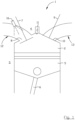
- figure 1 disclosing a schematic side view of a first embodiment of the inventive internal combustion engine 1
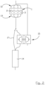
- figure 2 disclosing a schematic illustration of an internal combustion engine and an exhaust discharge arrangement.
- the internal combustion engine 1 comprises an engine block 3 provided with said set of combustion chambers or cylinders 2.
- Each combustion chamber 2 is defined radially by a stationary cylinder wall, and is defined axially by a stationary cylinder head 4 and a displaceable piston 5, respectively.
- the cylinder head 4 may be releasably connected to the engine block 3 or may be integral with the engine block 3.
- the piston 5 is configured displaceable back and forth in the axial direction within the combustion chamber 2 between a top dead center (TDC) and a bottom dead center (BDC), and is connected to a revolving crankshaft via a piston rod 6, wherein the linear movement of the piston 5 is converted into rotational movement of the crankshaft.
- TDC top dead center
- BDC bottom dead center
- the volume of the combustion chamber 2 changes cyclically as the piston 5 moves up and down in the cylinder.
- Each combustion chamber 2 is provided with at least one controllable intake valve 7 configured for opening and closing an intake port 8, at least one controllable exhaust valve 9 configured for opening and closing an exhaust port 10.
- each combustion chamber 2 comprises two intake ports and two exhaust ports, each port having a controllable valve that preferably are independently controlled. It shall be pointed out that two intake valves and/or the two exhaust valves, respectively, may be operated jointly. Thus, herein the invention is illustrated using one intake valve 7 and one exhaust valve 9, and it shall be realized that in applications having two intake valves and/or exhaust valves these valves can be kept closed or operated jointly with the disclosed valves.
- the combustion chamber 2 is provided with a spark plug 11. It shall be realized that the intake port 8, the exhaust port 10 and the spark plug 11 are arranged in the cylinder head 4.
- the intake valve 7 and the exhaust valve 9 are preferably of poppet valve type each having a valve stem and a valve disk attached to the lower end of the valve stem. In the closed position the valve disk abuts the material surrounding the corresponding port to prevent passage of fluid through the port, whereas in the open position the valve disc is displaced vertically down into the combustion chamber 2 in order to uncover the port and allow fluid to pass through the port and around the edge of the valve disk.
- the maximum displacement of the valves is preferably in the range 5-10 millimeters.
- Each of the intake valve 7 and the exhaust valve 9 is preferably operated by means of a corresponding valve actuator.
- a valve actuator allows the corresponding valve to be freely operated without the operation of the valve being slaved to the operation of the internal combustion engine 1, in particular the angular position of the crankshaft of the internal combustion engine, via a camshaft.
- a controllable valve operated by means of an actuator is for example described in the patent literature documents US2015184558 , SE1350849 and SE537203 .
- a controllable valve can be opened and closed at any time and the degree of lift of the valve is not fixed.
- the inventive internal combustion engine 1 comprises no camshaft, and is thus camshaft-free.
- the inventive internal combustion engine 1 is preferably also throttle-free.
- the actuator uses both pneumatic and hydraulic for its operation.
- the internal combustion engine 1 comprises an intake manifold 12 for providing air/gas to the combustion chamber 2 from an air intake, and an exhaust manifold 13 for evacuating exhaust gas from the combustion chamber 2 to an exhaust outlet via an exhaust discharge arrangement.
- an intake manifold 12 for providing air/gas to the combustion chamber 2 from an air intake
- an exhaust manifold 13 for evacuating exhaust gas from the combustion chamber 2 to an exhaust outlet via an exhaust discharge arrangement.
- at least one muffler (not shown) and/or at least one catalytic converter 14 are arranged adjacent the exhaust outlet, for decreasing the noise of operating of the internal combustion engine and/or for treating the exhaust gas, before the exhaust gas is eventually led off to the atmosphere.
- the exhaust discharge arrangement may comprise a pressure booster 15, constituted by a turbocharger, i.e. a pressure booster driven by exhaust gas.
- Air/gas for combustion is supplied to the combustion chamber 2 from the intake manifold 12 via the intake port 8 of each combustion chamber 2 of said set of combustion chambers.
- Each combustion chamber 2 is provided with an individual intake pipe/runner that is part of the intake manifold 12.
- the exhaust manifold 13 is connected to the exhaust port 10 of each combustion chamber 2 of said set of combustion chambers.
- Each combustion chamber 2 is provided with an individual exhaust pipe/runner that is part of the exhaust manifold 13.
- the internal combustion engine 1 further comprises an electronic control unit (ECU), wherein the ECU is configured to at least control the opening and closing of the intake valve 7 and the exhaust valve 9, using the corresponding actuators.
- the internal combustion engine 1 also comprises a sensor for monitoring the rotation of the crankshaft, wherein said sensor is operatively connected to said ECU.
- a fuel injector 16 is provided in the intake runner/pipe (intake manifold 12) for injecting fuel into the intake manifold 12 towards the intake port 8.
- the inventive internal combustion engine is provided with direct injection of the fuel into the combustion chambers 2.
- a four-stroke internal combustion engine conventionally proceeds through four strokes in one cycle, namely (1) Intake 0 to 180 CAD - this stroke beginning with the piston 5 at its highest position, i.e. top dead center closest to the cylinder head 4, and comprising displacement of the piston 5 downwards while a mixture of gas and fuel is introduced into the combustion chamber 2, (2) Compression 180 to 360 CAD - this stroke beginning with the piston 5 at its lowest position, i.e.
- the inventive internal combustion engine 1 is configured to be operated in at least a catalytic converter warm-up mode, i.e. a cold start mode. According to the inventive method the internal combustion engine 1 is operated in the catalytic converter warm-up mode.
- the output torque [Nm] of the internal combustion engine 1 is dependent on engine speed [rpm], and the output torque of the internal combustion engine is in this context equivalent with driver/operator requested output torque via an accelerator pedal.
- the driver/operator usually requests low or moderate output torque via the accelerator pedal.
- the ECU is configured to adjust the filling rate of the combustion chambers 2 in view of the engine speed and the requested output torque, i.e. the amount of air/gas going into a combustion chamber 2 in relation to the volume of the combustion chamber.
- the ECU is also configured for varying the amount of fuel injected into each combustion chamber to provide a suitable relationship, or lambda value, between oxygen and fuel.
- the internal combustion engine 1 is configured to shift from catalytic converter warm-up mode to normal mode (i.e. Low/Part Load mode, High Load mode, Sport mode, economy mode, etc.) when the catalytic converter 14 has reached its working temperature, i.e. when the catalytic converter 14 is ignited.
- normal mode i.e. Low/Part Load mode, High Load mode, Sport mode, economy mode, etc.
- Different sensors upstream and downstream the catalytic converter 14 are used in a conventional way to determine when the catalytic converter 14 is treated as ignited.
- the inventive internal combustion engine 1 is configured to perform the inventive method comprising several essential activities/steps. It shall be pointed out that the mutual order of the activities listed in the claims is not entirely delimiting for the invention.
- the essential activities/steps of the invention are constituted by:
- the operation of the internal combustion engine also comprises suitable/conventional activities/steps, i.e. compression stroke and beginning of power stroke.
- the exhaust port 10 becomes fully closed and the intake port 8 starts to open before the piston 5 reaches top dead center during the exhaust stroke.
- the substantial mixing of the fuel and gas takes place in the intake manifold 12.
- the fuel is evaporated and the exhaust gas is cooled down.
- substantially all fuel is injected when the exhaust port 10 is closed, the intake port 8 is open and exhaust gas is pressed into the intake manifold 12 by means of the piston 5.
- the fuel injection takes place within 60 CAD, preferably within 40 CAD. Best mixing of the exhaust gas and fuel is achieved if the fuel is injected directly into the flow of exhaust gas that is pressed into the intake manifold 12.
- the fuel is added/injected into the intake manifold 12 by means of the fuel injector 16, and the fuel injection preferably takes place in the range that start when the intake port 8 becomes fully closed during the compression stroke, and that stop when the intake port 8 becomes fully closed in connection with the end of the cycle.
- the fuel can be added/injected after the intake valve 7 has become closed after the intake stroke of the present cycle, either when the intake valve 7 is still closed and/or when the intake port 8 is opened during the exhaust stroke.
- the fuel is injected into the combustion chamber 2 by means of the fuel injector 16 when the intake valve 7 is open, the exhaust valve 9 is closed and all the exhaust gas is forced/pressed into the intake manifold 12.
- the fuel injection takes place in the range that start when the exhaust port 10 becomes fully closed during the exhaust stroke, and that stop when the intake port 8 becomes fully closed in connection with the end of the cycle.
- the fuel injection starts in the range 610 to 670 CAD.
- the fuel injection takes place in the range that start at 270 and that stop when the intake port 8 starts to open during the exhaust stroke, i.e. all fuel is injected when the intake valve 7 is closed such that all fuel is ready to mix with (be added to) the exhaust gas when the intake valve 7 is opened and the exhaust gas is pressed into the intake manifold 12 by means of the piston 5.
- the exhaust port 10 shall start to open as soon as possible after ignition/combustion of the gas-fuel-mixture in order to evacuate as warm exhaust gases as possible via the exhaust manifold 13 to the catalytic converter 14. However, enough chemical energy of the fuel has to be converted to kinetic energy to be able to turn the crankshaft of the internal combustion engine 1, before the exhaust port 10 starts to open during the power stroke.
- the internal combustion engine 1 has a predetermined cold start rpm, usually in the range 1000-1500 rpm and for instance 1100 rpm.
- the exhaust port 10 is preferably default to open at a predetermined CAD, for instance 450 CAD.
- the ECU determine the actual rpm and if there is a difference between the actual rpm and the predetermined cold start rpm, the moment the exhaust port 10 starts to open is revised.
- the actual rpm is too low the exhaust port 10 is kept closed a longer period, and when the actual rpm is too high the exhaust port 10 is kept closed a shorter period.
- the moment the exhaust port 10 starts to open is preferably altered in steps of 5 CAD. Preferably, this procedure takes place during the entire cold start period.
- the exhaust port 10 starts to open in the range 450 to 495 CAD, most preferably in the range 450 to 490 CAD.
- the moment the exhaust port 10 becomes fully closed and the moment the intake port 8 starts to open takes place within 40 CAD, preferably within 20 CAD.
- the valve overlap period shall be as short as possible, but long enough for the exhaust gas to be continuously evacuated from the combustion chamber also during the shift from open exhaust valve 9 to open intake valve 7.
- the exhaust port 10 becomes fully closed in the range 630 to 690 CAD, and preferably the intake port 8 starts to open in the range 610 to 670 CAD.
- the intake valve 7 starts to open before the exhaust valve 9 is fully closed.
- the intake port 8 starts to open in the range 665 to 670 CAD. It is most preferred that the exhaust port 10 becomes fully closed in the range 675 to 690. In order to prevent knocking at the same time as enough internal EGR is achieved during warm-up.
- the volume of the individual intake runner should be big enough to ensure that the exhaust gas pressed into the intake manifold 12 by means of the piston 5 does not slip over into an intake runner of a neighboring combustion chamber 2.
- the mixing of the fuel and exhaust gas takes place in the individual intake runner and is sucked into the same combustion chamber during the intake stroke of the following cycle.
- the intake valve 7 can be open or fully open when the piston 5 reaches top dead center, especially gasoline engines, and in some applications the intake valve 7 has to be closed when the piston 5 reaches top dead center in order not to become damaged by the piston 5, especially diesel engines.
- the intake valve 7 may be kept open past 720 CAD, at most until 720+20 CAD and preferably at most until 720+10 CAD.
- the intake valve 7 has to be fully closed at 710 CAD, and it shall be pointed out that this may also be applied to the first type application.
- the intake port 8 is kept closed until at least 90 CAD, preferably until at least 120 CAD and most preferably until at least 150 CAD, in order to create under pressure in the combustion chamber 2, in order for the other combustion chambers to create more work and thereby more and warmer exhaust gas are generated.
- the intake port 8 becomes fully closed in the range 180 to 240 CAD, most preferably in the range 180 to 220 CAD. The earlier the intake port 8 is closed during the compression stroke the higher over pressure is generated, i.e. the engine needs to perform more work.
- combustion chambers of the set of combustion chambers of the internal combustion engine 1 are active during the catalytic converter warm-up mode.
- the activated combustion chambers 2 need to perform more work and thereby produces more and warmer exhaust gas.
- at least two combustion chambers 2 of the set of combustion chambers are activated and at least one combustion chamber 2 of the set of combustion chambers is deactivated when the internal combustion engine 1 is operated in said catalytic converter warm-up mode.
- a combustion chamber is deactivated it is provided with any fuel.
- the intake port and the exhaust port of the deactivated combustion chamber are closed the entire cycle.
- the intake port of the deactivated combustion chamber may be operated to be closed during the intake stroke to create under pressure, open shortly in connection with 180 CAD, closed during the compression stroke to create over pressure, open shortly in connection with 360 CAD, closed during the power stroke to create under pressure, open shortly in connection with 540 CAD, closed during the exhaust stroke to create over pressure, open shortly in connection with 720 CAD.
- the activated combustion chambers has to perform more work and thereby produces more and warmer exhaust gas.
- the internal combustion engine 1 comprises a pressure booster 15 constituted by a turbocharger, and it is preferred that the exhaust gas evacuated from the combustion chamber 2 via the exhaust port 10 bypass the pressure booster 15, via a bypass 17.
- the ECU or similar computer readable medium having stored thereon a computer program product comprises instructions to cause the inventive internal combustion engine 1 to execute the steps of the inventive method.
- controlling the opening is also to be understood as controlling the closing.
- Controlling the opening is further to be understood as controlling any of the valve lift, the duration of opening, and when in the operation/cycle of the internal combustion engine the valve is opened.
Landscapes
- Engineering & Computer Science (AREA)
- Chemical & Material Sciences (AREA)
- Combustion & Propulsion (AREA)
- Mechanical Engineering (AREA)
- General Engineering & Computer Science (AREA)
- Chemical Kinetics & Catalysis (AREA)
- Output Control And Ontrol Of Special Type Engine (AREA)
- Exhaust Gas After Treatment (AREA)
Description
- The present invention relates generally to the field of internal combustion engines suitable for powering a vehicle, such as a car or a truck, a boat, etc., or a machine such as an electric power generator or the like. Further, the present invention relates specifically to an internal combustion engine suitable for a performance car, i.e. a car that is designed and constructed specifically for speed. The internal combustion engine is not restricted to be powered by any specific type of fuel, i.e. both liquid fuel and gaseous fuel are conceivable.
- The inventive internal combustion engine comprises a set of combustion chambers, each combustion chamber being provided with a controllable intake valve configured for opening and closing an intake port, a controllable exhaust valve configured for opening and closing an exhaust port, a piston displaceable back and forth in said combustion chamber between a top dead center (TDC) and a bottom dead center (BDC), and a fuel injector. The internal combustion engine further comprises an intake manifold connected to the intake port of each combustion chamber of said set of combustion chambers.
- The invention also relates to a method of operating such an internal combustion engine.
- In internal combustion engines operated in four-stroke cycles, a mixture of air and fuel is provided into a combustion chamber, i.e. cylinder, during an intake stroke. The air-fuel mixture is compressed during a compression stroke, and in connection with the end of the compression stroke the air-fuel mixture is ignited, either by a spark plug or spontaneously due to the compression. The heat and energy released by the burning of the air-fuel mixture causes a further rise in pressure in the combustion chamber which is used to do work against a movable wall of the combustion chamber, i.e. the piston, which work is converted into rotational movement of a crank shaft attached to the piston via a piston rod, during a power stroke. The exhaust gas formed from the burning of the air-fuel mixture is then evacuated from the combustion chamber, during an exhaust stroke, and thereafter a new cycle begins. The cycles of the different combustion chambers of the internal combustion engine are offset in relation to each other.
- With rising concerns of the environment and pollution caused by the exhaust gas from internal combustion engines there is a need to lower harmful emissions from internal combustion engines while at the same time maintaining or increasing the efficiency of conversion of the chemical energy in the fuel to kinetic energy of the crankshaft, thereto it is a need to decrease fuel consumption.
- In connection with cold starts of an internal combustion engine, i.e. when the catalytic converter of the exhaust discharge arrangement is not warmed up and has not yet reached its working temperature, the catalytic converter cannot fully convert the toxic emissions into less toxic substances. A normal time for igniting a catalytic converter is about 5 minutes, and most of the total pollution from the internal combustion engine is emitted during the warm-up period.
- One known way to reduce the warm-up period is to use electric heating coils in the catalytic converter or use a smaller catalytic converter arranged upstream the main catalytic converter.
- Both these systems requests expensive auxiliary equipment. An example of an engine with an warm-up system is given in
FR 2 918 704 A3 - The present invention aims at obviating the disadvantages and failings of previously known internal combustion engines and at providing an improved internal combustion engine. A primary object of the present invention is to provide an improved internal combustion engine of the initially defined type generating less toxic emission during cold starts.
- It is another object of the present invention is to provide an improved internal combustion engine having a decreased warm-up period of the catalytic converter.
- It is another object of the present invention to provide an improved internal combustion engine having decreased heat losses.
- It is yet another object of the invention is to provide an improved internal combustion engine having a more stable ignition from cycle to cycle.
- It is another object of the present invention to provide an improved internal combustion engine having internal recirculation of exhaust gas, in order to reduce the amount of unburnt fuel reaching the catalytic converter.
- According to the invention at least the primary object is attained by means of the initially defined internal combustion engine and method having the features defined in the independent claims. Preferred embodiments of the present invention are further defined in the dependent claims.
- The present invention is a strategy for controlling the operation of an internal combustion engine during a catalytic converter warm-up mode in order to minimize fuel consumption and minimize emissions, during the warm-up period of the catalytic converter.
- According to a first aspect of the present invention, there is provided an internal combustion engine of the initially defined type, the internal combustion engine being configured to be operated in a catalytic converter warm-up mode, wherein each combustion chamber is configured to be driven in four-stroke operation comprising a 720 crank angle degrees cycle, wherein the internal combustion engine is configured to perform the following activities: open the intake port, the intake port starting to open in the range 90 to 180 CAD, and close the intake port, the intake port becomes fully closed in the range 180 to 270 CAD, open the exhaust port during the power stroke, the exhaust port starting to open in the range 405 to 495 CAD, open the intake port during the exhaust stroke, the intake port starting to open in the range 610 to 690 CAD, and close the exhaust port during the exhaust stroke, the exhaust port becomees fully closed in the range 630 to 710 CAD, wherein the exhaust gas is forced into the intake manifold by means of the piston, mix fuel and exhaust gas in the intake manifold, and close the intake port, the intake port becomes fully closed in the range 700 to 720+20 CAD.
- According to a second aspect of the present invention, there is provided a method for controlling such an internal combustion engine.
- Thus, the present invention is based on the insight that by minimizing the mechanical efficiency of the internal combustion engine and maximizing the thermal efficiency of the internal combustion engine, i.e. by having less combustion energy to be converted into kinetic energy and the exhaust gas is expelled from the combustion chamber at a higher temperature, and having internal exhaust gas recirculation, the raw emissions during cold start are reduced and the warm-up period of the catalytic converter is reduced.
- According to a preferred embodiment of the present invention, the step of starting to open the intake port during the intake stroke takes place in the range 120 to 180 CAD, even more preferred within the range 150 to 180 CAD. The longer the intake port is closed during the intake stroke the greater under pressure in the combustion chamber before the intake port is opened, and thereby the engine needs to generate more work and thereby more and warmer exhausted gases are generated.
- According to a preferred embodiment of the present invention, during the exhaust stroke, the intake port starts to open in the range 665 to 690 CAD and the exhaust port becomes fully closed in the range 675 to 710 CAD. According to a preferred embodiment of the present invention, the method comprises the activity of injecting fuel into the intake manifold, fuel injection taking place in the range that start when the intake port becomes fully closed during the compression stroke, and that stop when the intake port becomes fully closed in connection with the end of the cycle. Preferably, the fuel injection takes place in the range that start when the exhaust port becomes fully closed during the exhaust stroke, and that stop when the intake port becomes fully closed in connection with the end of the cycle. Thereby, the risk of having fuel escaping through the exhaust port is completely eliminated.
- According to a preferred embodiment of the present invention, at least two combustion chambers of the set of combustion chambers are activated and at least one combustion chamber of the set of combustion chambers is deactivated when the internal combustion engine is operated in said catalytic converter warm-up mode. Thereby, more exhaust gas having higher temperature is generated in comparison of having all combustion chambers activated.
- Further advantages with and features of the invention will be apparent from the other dependent claims as well as from the following detailed description of preferred embodiments.
- A more complete understanding of the abovementioned and other features and advantages of the present invention will be apparent from the following detailed description of preferred embodiments in conjunction with the appended drawing, wherein:
-
Fig. 1 is a schematic side view of a combustion chamber of an internal combustion engine according to the present invention, and -
Fig. 2 is a schematic illustration of an internal combustion engine and an exhaust discharge arrangement. - The present invention relates generally to the field of internal combustion engines suitable for powering a vehicle or a machine. The inventive internal combustion engine, generally designated 1, comprises a set of combustion chambers. The set/plurality of combustion chambers comprises at least two
separate combustion chambers 2, also known as cylinders. However, theinternal combustion engine 1 may comprise more combustion chambers, such as 3, 4, 6, 8, 10, 12 or 16. Eachcombustion chamber 2 is preferably cylindrical. - The
internal combustion engine 1 is a four-stroke engine, i.e. configured to be driven in four-stroke operation comprising a 720 crank angle degrees (CAD) cycle. The four strokes are "intake" during which air/gas and fuel are delivered into thecombustion chamber 2, "compression" during which the air-fuel mixture in thecombustion chamber 2 is compressed, "power/combustion" during which the air-fuel mixture is ignited and combusted, and "exhaust" during which the exhaust gas formed by the combustion of the air-fuel mixture is evacuated, also known as scavenged, from thecombustion chamber 2. Preferably theinternal combustion engine 1 is constituted by a spark-ignition engine, i.e. in which the air-fuel mixture is ignited by a spark from a sparkplug, but may also be constituted by a spontaneous/compression-ignition engine. Theinternal combustion engine 1 is preferably configured to be driven by petrol/gasoline, but may alternatively be configured to be driven by diesel, gas, ethanol, etc. and/or a mixture of said fuels. - Reference is made to
figure 1 disclosing a schematic side view of a first embodiment of the inventiveinternal combustion engine 1, and tofigure 2 disclosing a schematic illustration of an internal combustion engine and an exhaust discharge arrangement. - The
internal combustion engine 1 comprises anengine block 3 provided with said set of combustion chambers orcylinders 2. Eachcombustion chamber 2 is defined radially by a stationary cylinder wall, and is defined axially by astationary cylinder head 4 and adisplaceable piston 5, respectively. Thecylinder head 4 may be releasably connected to theengine block 3 or may be integral with theengine block 3. Thepiston 5 is configured displaceable back and forth in the axial direction within thecombustion chamber 2 between a top dead center (TDC) and a bottom dead center (BDC), and is connected to a revolving crankshaft via a piston rod 6, wherein the linear movement of thepiston 5 is converted into rotational movement of the crankshaft. Thus, the volume of thecombustion chamber 2 changes cyclically as thepiston 5 moves up and down in the cylinder. - Each
combustion chamber 2 is provided with at least one controllable intake valve 7 configured for opening and closing anintake port 8, at least one controllable exhaust valve 9 configured for opening and closing anexhaust port 10. Preferably, eachcombustion chamber 2 comprises two intake ports and two exhaust ports, each port having a controllable valve that preferably are independently controlled. It shall be pointed out that two intake valves and/or the two exhaust valves, respectively, may be operated jointly. Thus, herein the invention is illustrated using one intake valve 7 and one exhaust valve 9, and it shall be realized that in applications having two intake valves and/or exhaust valves these valves can be kept closed or operated jointly with the disclosed valves. - Thereto, in the disclosed embodiment the
combustion chamber 2 is provided with aspark plug 11. It shall be realized that theintake port 8, theexhaust port 10 and thespark plug 11 are arranged in thecylinder head 4. - The intake valve 7 and the exhaust valve 9 are preferably of poppet valve type each having a valve stem and a valve disk attached to the lower end of the valve stem. In the closed position the valve disk abuts the material surrounding the corresponding port to prevent passage of fluid through the port, whereas in the open position the valve disc is displaced vertically down into the
combustion chamber 2 in order to uncover the port and allow fluid to pass through the port and around the edge of the valve disk. The maximum displacement of the valves is preferably in the range 5-10 millimeters. - Each of the intake valve 7 and the exhaust valve 9 is preferably operated by means of a corresponding valve actuator. Thus, in the context of the present invention a valve actuator allows the corresponding valve to be freely operated without the operation of the valve being slaved to the operation of the
internal combustion engine 1, in particular the angular position of the crankshaft of the internal combustion engine, via a camshaft. A controllable valve operated by means of an actuator is for example described in the patent literature documentsUS2015184558 ,SE1350849 SE537203 internal combustion engine 1 comprises no camshaft, and is thus camshaft-free. The inventiveinternal combustion engine 1 is preferably also throttle-free. Preferably, the actuator uses both pneumatic and hydraulic for its operation. - The
internal combustion engine 1 comprises anintake manifold 12 for providing air/gas to thecombustion chamber 2 from an air intake, and anexhaust manifold 13 for evacuating exhaust gas from thecombustion chamber 2 to an exhaust outlet via an exhaust discharge arrangement. Usually at least one muffler (not shown) and/or at least onecatalytic converter 14 are arranged adjacent the exhaust outlet, for decreasing the noise of operating of the internal combustion engine and/or for treating the exhaust gas, before the exhaust gas is eventually led off to the atmosphere. Thereto, the exhaust discharge arrangement may comprise apressure booster 15, constituted by a turbocharger, i.e. a pressure booster driven by exhaust gas. - Air/gas for combustion is supplied to the
combustion chamber 2 from theintake manifold 12 via theintake port 8 of eachcombustion chamber 2 of said set of combustion chambers. Eachcombustion chamber 2 is provided with an individual intake pipe/runner that is part of theintake manifold 12. Theexhaust manifold 13 is connected to theexhaust port 10 of eachcombustion chamber 2 of said set of combustion chambers. Eachcombustion chamber 2 is provided with an individual exhaust pipe/runner that is part of theexhaust manifold 13. - The
internal combustion engine 1 further comprises an electronic control unit (ECU), wherein the ECU is configured to at least control the opening and closing of the intake valve 7 and the exhaust valve 9, using the corresponding actuators. Theinternal combustion engine 1 also comprises a sensor for monitoring the rotation of the crankshaft, wherein said sensor is operatively connected to said ECU. - In the disclosed embodiment, a
fuel injector 16 is provided in the intake runner/pipe (intake manifold 12) for injecting fuel into theintake manifold 12 towards theintake port 8. In an alternative embodiment the inventive internal combustion engine is provided with direct injection of the fuel into thecombustion chambers 2. - As is known to a person skilled in the art a four-stroke internal combustion engine conventionally proceeds through four strokes in one cycle, namely (1) Intake 0 to 180 CAD - this stroke beginning with the
piston 5 at its highest position, i.e. top dead center closest to thecylinder head 4, and comprising displacement of thepiston 5 downwards while a mixture of gas and fuel is introduced into thecombustion chamber 2, (2) Compression 180 to 360 CAD - this stroke beginning with thepiston 5 at its lowest position, i.e. bottom dead center, and comprising closing the intake valve 7 and moving thepiston 5 upwards towards thecylinder head 4 while compressing the gas-fuel mixture, (3) Power 360 to 540 CAD - igniting the gas-fuel mixture wherein the resulting pressure caused by the combustion of the fuel will displace thepiston 5 downwards and away from thecylinder head 4, and (4) Exhaust 540 to 720 CAD - opening the exhaust valve 9 for allowing the exhaust gas formed by the combustion of the gas-fuel mixture to evacuate from thecombustion chamber 2 while thepiston 5 once more is displaced towards the top dead center. The ignition of the gas-fuel mixture takes place in connection with thepiston 5 being located at the upper dead center between the compression stroke and the power stroke. - The inventive
internal combustion engine 1 is configured to be operated in at least a catalytic converter warm-up mode, i.e. a cold start mode. According to the inventive method theinternal combustion engine 1 is operated in the catalytic converter warm-up mode. The output torque [Nm] of theinternal combustion engine 1 is dependent on engine speed [rpm], and the output torque of the internal combustion engine is in this context equivalent with driver/operator requested output torque via an accelerator pedal. During the catalytic converter warm-up mode, the driver/operator usually requests low or moderate output torque via the accelerator pedal. - The ECU is configured to adjust the filling rate of the
combustion chambers 2 in view of the engine speed and the requested output torque, i.e. the amount of air/gas going into acombustion chamber 2 in relation to the volume of the combustion chamber. The ECU is also configured for varying the amount of fuel injected into each combustion chamber to provide a suitable relationship, or lambda value, between oxygen and fuel. - The
internal combustion engine 1 is configured to shift from catalytic converter warm-up mode to normal mode (i.e. Low/Part Load mode, High Load mode, Sport mode, Economy mode, etc.) when thecatalytic converter 14 has reached its working temperature, i.e. when thecatalytic converter 14 is ignited. Different sensors upstream and downstream thecatalytic converter 14 are used in a conventional way to determine when thecatalytic converter 14 is treated as ignited. - The inventive
internal combustion engine 1 is configured to perform the inventive method comprising several essential activities/steps. It shall be pointed out that the mutual order of the activities listed in the claims is not entirely delimiting for the invention. The essential activities/steps of the invention are constituted by: - opening the
intake port 8, theintake port 8 starting to open in the range 90 to 180 CAD, and closing theintake port 8, theintake port 8 becomes fully closed in the range 180 to 270 CAD, - opening the
exhaust port 10 during the power stroke, theexhaust port 10 starting to open in the range 405 to 495 CAD, - opening the
intake port 8 during the exhaust stroke, theintake port 8 starting to open in the range 610 to 690 CAD, and closing theexhaust port 10 during the exhaust stroke, theexhaust port 10 becomes fully closed in the range 630 to 710 CAD, wherein the exhaust gas is forced into theintake manifold 12 by means of thepiston 5, - mixing fuel and exhaust gas in the
intake manifold 12, and - closing the
intake port 8, theintake port 8 becomes fully closed in the range 700 to 720+20 CAD. - It shall be realized that in addition to the essential activities/steps mentioned above, the operation of the internal combustion engine also comprises suitable/conventional activities/steps, i.e. compression stroke and beginning of power stroke.
- Thus, according to the invention the
exhaust port 10 becomes fully closed and theintake port 8 starts to open before thepiston 5 reaches top dead center during the exhaust stroke. Irrespective of the fuel is added/injected into theintake manifold 12 or into thecombustion chamber 2, the substantial mixing of the fuel and gas takes place in theintake manifold 12. During the mixing of the exhaust gas and fuel in the intake manifold, the fuel is evaporated and the exhaust gas is cooled down. Preferably substantially all fuel is injected when theexhaust port 10 is closed, theintake port 8 is open and exhaust gas is pressed into theintake manifold 12 by means of thepiston 5. Preferably the fuel injection takes place within 60 CAD, preferably within 40 CAD. Best mixing of the exhaust gas and fuel is achieved if the fuel is injected directly into the flow of exhaust gas that is pressed into theintake manifold 12. - According to the disclosed embodiment the fuel is added/injected into the
intake manifold 12 by means of thefuel injector 16, and the fuel injection preferably takes place in the range that start when theintake port 8 becomes fully closed during the compression stroke, and that stop when theintake port 8 becomes fully closed in connection with the end of the cycle. Thus, the fuel can be added/injected after the intake valve 7 has become closed after the intake stroke of the present cycle, either when the intake valve 7 is still closed and/or when theintake port 8 is opened during the exhaust stroke. According to the alternative embodiment the fuel is injected into thecombustion chamber 2 by means of thefuel injector 16 when the intake valve 7 is open, the exhaust valve 9 is closed and all the exhaust gas is forced/pressed into theintake manifold 12. - In one embodiment the fuel injection takes place in the range that start when the
exhaust port 10 becomes fully closed during the exhaust stroke, and that stop when theintake port 8 becomes fully closed in connection with the end of the cycle. Preferably the fuel injection starts in the range 610 to 670 CAD. Thus, it is preferred to inject the fuel when the intake valve 7 is open during the exhaust stroke and the exhaust gas flow into theintake manifold 12. According to another embodiment the fuel injection takes place in the range that start at 270 and that stop when theintake port 8 starts to open during the exhaust stroke, i.e. all fuel is injected when the intake valve 7 is closed such that all fuel is ready to mix with (be added to) the exhaust gas when the intake valve 7 is opened and the exhaust gas is pressed into theintake manifold 12 by means of thepiston 5. - During the power stroke, the
exhaust port 10 shall start to open as soon as possible after ignition/combustion of the gas-fuel-mixture in order to evacuate as warm exhaust gases as possible via theexhaust manifold 13 to thecatalytic converter 14. However, enough chemical energy of the fuel has to be converted to kinetic energy to be able to turn the crankshaft of theinternal combustion engine 1, before theexhaust port 10 starts to open during the power stroke. Theinternal combustion engine 1 has a predetermined cold start rpm, usually in the range 1000-1500 rpm and for instance 1100 rpm. Upon start of theinternal combustion engine 1, theexhaust port 10 is preferably default to open at a predetermined CAD, for instance 450 CAD. Thereafter the ECU determine the actual rpm and if there is a difference between the actual rpm and the predetermined cold start rpm, the moment theexhaust port 10 starts to open is revised. When the actual rpm is too low theexhaust port 10 is kept closed a longer period, and when the actual rpm is too high theexhaust port 10 is kept closed a shorter period. The moment theexhaust port 10 starts to open is preferably altered in steps of 5 CAD. Preferably, this procedure takes place during the entire cold start period. Preferably theexhaust port 10 starts to open in the range 450 to 495 CAD, most preferably in the range 450 to 490 CAD. - According to a preferred embodiment the moment the
exhaust port 10 becomes fully closed and the moment theintake port 8 starts to open, takes place within 40 CAD, preferably within 20 CAD. Thus, the valve overlap period shall be as short as possible, but long enough for the exhaust gas to be continuously evacuated from the combustion chamber also during the shift from open exhaust valve 9 to open intake valve 7. Preferably theexhaust port 10 becomes fully closed in the range 630 to 690 CAD, and preferably theintake port 8 starts to open in the range 610 to 670 CAD. Preferably the intake valve 7 starts to open before the exhaust valve 9 is fully closed. Alternatively, it is preferred that theintake port 8 starts to open in the range 665 to 690 CAD, and that theexhaust port 10 becomes fully closed in the range 675 to 710 CAD. It is most preferred that theintake port 8 starts to open in the range 665 to 670 CAD. It is most preferred that theexhaust port 10 becomes fully closed in the range 675 to 690. In order to prevent knocking at the same time as enough internal EGR is achieved during warm-up. - It shall be pointed out that according to a preferred embodiment the volume of the individual intake runner should be big enough to ensure that the exhaust gas pressed into the
intake manifold 12 by means of thepiston 5 does not slip over into an intake runner of a neighboringcombustion chamber 2. Thus, the mixing of the fuel and exhaust gas takes place in the individual intake runner and is sucked into the same combustion chamber during the intake stroke of the following cycle. - In some applications the intake valve 7 can be open or fully open when the
piston 5 reaches top dead center, especially gasoline engines, and in some applications the intake valve 7 has to be closed when thepiston 5 reaches top dead center in order not to become damaged by thepiston 5, especially diesel engines. In the first type applications the intake valve 7 may be kept open past 720 CAD, at most until 720+20 CAD and preferably at most until 720+10 CAD. According the second type application the intake valve 7 has to be fully closed at 710 CAD, and it shall be pointed out that this may also be applied to the first type application. According to the inventive method theintake port 8 is kept closed until at least 90 CAD, preferably until at least 120 CAD and most preferably until at least 150 CAD, in order to create under pressure in thecombustion chamber 2, in order for the other combustion chambers to create more work and thereby more and warmer exhaust gas are generated. Thereto, due to the high speed of the gas-fuel mixture when theintake port 8 is open, thecombustion chamber 2 is overfilled and thereby more and warmer exhaust gas are generated. Since the exhaust gas and fuel is mixed in the intake manifold, a better and more efficient combustion is obtained generating less emission, and a more stable combustion from cycle to cycle resulting in decreased fuel consumption. Preferably theintake port 8 becomes fully closed in the range 180 to 240 CAD, most preferably in the range 180 to 220 CAD. The earlier theintake port 8 is closed during the compression stroke the higher over pressure is generated, i.e. the engine needs to perform more work. - Preferably not all combustion chambers of the set of combustion chambers of the
internal combustion engine 1 are active during the catalytic converter warm-up mode. By having somecombustion chambers 2 deactivated, the activatedcombustion chambers 2 need to perform more work and thereby produces more and warmer exhaust gas. Preferably, at least twocombustion chambers 2 of the set of combustion chambers are activated and at least onecombustion chamber 2 of the set of combustion chambers is deactivated when theinternal combustion engine 1 is operated in said catalytic converter warm-up mode. When a combustion chamber is deactivated it is provided with any fuel. In one embodiment the intake port and the exhaust port of the deactivated combustion chamber are closed the entire cycle. - According to another embodiment the intake port of the deactivated combustion chamber may be operated to be closed during the intake stroke to create under pressure, open shortly in connection with 180 CAD, closed during the compression stroke to create over pressure, open shortly in connection with 360 CAD, closed during the power stroke to create under pressure, open shortly in connection with 540 CAD, closed during the exhaust stroke to create over pressure, open shortly in connection with 720 CAD. Thereby the activated combustion chambers has to perform more work and thereby produces more and warmer exhaust gas.
- In the disclosed embodiment the
internal combustion engine 1 comprises apressure booster 15 constituted by a turbocharger, and it is preferred that the exhaust gas evacuated from thecombustion chamber 2 via theexhaust port 10 bypass thepressure booster 15, via abypass 17. - The ECU or similar computer readable medium having stored thereon a computer program product comprises instructions to cause the inventive
internal combustion engine 1 to execute the steps of the inventive method. - The invention is not limited only to the embodiments described above and shown in the drawings, which primarily have an illustrative and exemplifying purpose. This patent application is intended to cover all adjustments and variants of the preferred embodiments described herein, thus the present invention is defined by the wording of the appended claims and thus, the equipment may be modified in all kinds of ways within the scope of the appended claims.
- It shall be pointed out that controlling the opening is also to be understood as controlling the closing. Controlling the opening is further to be understood as controlling any of the valve lift, the duration of opening, and when in the operation/cycle of the internal combustion engine the valve is opened.
- It shall also be pointed out that all information about/concerning terms such as above, under, upper, lower, etc., shall be interpreted/read having the equipment oriented according to the figures, having the drawings oriented such that the references can be properly read. Thus, such terms only indicates mutual relations in the shown embodiments, which relations may be changed if the inventive equipment is provided with another structure/design.
Claims (13)
- An internal combustion engine (1) comprising a set of combustion chambers (2), each combustion chamber (2) being provided with:- a controllable intake valve (7) configured for opening and closing an intake port (8),- a controllable exhaust valve (9) configured for opening and closing an exhaust port (10),- a piston (5) displaceable back and forth in said combustion chamber (2) between a top dead center (TDC) and a bottom dead center (BDC), and- a fuel injector (16),the internal combustion engine (1) further comprising an intake manifold (12) connected to the intake port (8) of each combustion chamber of said set of combustion chambers (2),and where the internal combustion engine (1) is configured to be operated in a catalytic converter warm-up mode, wherein each combustion chamber (2) is configured to be driven in four-stroke operation comprising a 720 crank angle degrees cycle, wherein the internal combustion engine (1) is configured to perform the following activities:- open the intake port (8), the intake port (8) starting to open in the range 90 to 180 CAD, and close the intake port (8), the intake port (8) becomes fully closed in the range 180 to 270 CAD,- open the exhaust port (10) (10) during the power stroke, the exhaust port (10) starting to open in the range 405 to 495 CAD,- open the intake port (8) during the exhaust stroke, the intake port (8) starting to open in the range 610 to 690 CAD, and close the exhaust port (10) during the exhaust stroke, the exhaust port (10) becomes fully closed in the range 630 to 710 CAD, wherein the exhaust gas is forced into the intake manifold (12) by means of the piston (5),- mix fuel and exhaust gas in the intake manifold (12), and- close the intake port (8), the intake port (8) becomes fully closed in the range 700 to 720+20 CAD.
- A method for controlling an internal combustion engine (1) comprising a set of combustion chambers (2), each combustion chamber (2) being provided with:- a controllable intake valve (7) configured for opening and closing an intake port (8),- a controllable exhaust valve (9) configured for opening and closing an exhaust port (10),- a piston (5) displaceable back and forth in said combustion chamber (2) between a top dead center (TDC) and a bottom dead center (BDC), and- a fuel injector (16),the internal combustion engine (1) (1) further comprising an intake manifold (12) connected to the intake port (8) of each combustion chamber of said set of combustion chambers (2),and with the internal combustion engine (1) being operated in a catalytic converter warm-up mode, wherein each combustion chamber (2) is driven in four-stroke operation comprising a 720 crank angle degrees cycle, wherein the method comprises the activities:- opening the intake port (8), the intake port (8) starting to open in the range 90 to 180 CAD, and closing the intake port (8), the intake port (8) becomes fully closed in the range 180 to 270 CAD,- opening the exhaust port (10) during the power stroke, the exhaust port (10) starting to open in the range 405 to 495 CAD,- opening the intake port (8) during the exhaust stroke, the intake port (8) starting to open in the range 610 to 690 CAD, and closing the exhaust port (10) during the exhaust stroke, the exhaust port (10) becomes fully closed in the range 630 to 710 CAD, wherein the exhaust gas is forced into the intake manifold (12) by means of the piston (5),- mixing fuel and exhaust gas in the intake manifold (12), and- closing the intake port (8), the intake port (8) becomes fully closed in the range 700 to 720+20 CAD.
- The method according to claim 2, wherein the intake port (8) starting to open in the range 120 to 180 CAD, preferably in the range 150 to 180 CAD.
- The method according to claim 2 or 3, wherein, during the exhaust stroke, the intake port (8) starts to open in the range 665 to 690 CAD and the exhaust port (10) becomes fully closed in the range 675 to 710 CAD.
- The method according to any of claims 2-4, wherein the method comprises the activity:- injecting fuel into the intake manifold (12), fuel injection taking place in the range that start when the intake port (8) becomes fully closed during the compression stroke, and that stop when the intake port (8) becomes fully closed in connection with the end of the cycle.
- The method according to claim 5, wherein fuel injection takes place in the range that start when the exhaust port (10) becomes fully closed during the exhaust stroke, and that stop when the intake port (8) becomes fully closed in connection with the end of the cycle.
- The method according to claim 5 or 6, wherein fuel injection takes place within 60 CAD, preferably within 40 CAD.
- The method according to any of claims 2-7, wherein the exhaust port (10) starts to open in the range 450 to 495 CAD.
- The method according to any of claims 2-8, wherein the moment the exhaust port (10) becomes fully closed during the exhaust stroke and the moment the intake port (8) starts to open during the exhaust stroke, takes place within 40 CAD, preferably within 20 CAD.
- The method according to any of claims 2-9, wherein the intake port (8) starts to open in the range 610 to 670 CAD, and the exhaust port (10) becomes fully closed in the range 630 to 690 CAD.
- The method according to any of claims 2-10, wherein at least two combustion chambers (2) of the set of combustion chambers are activated and at least one combustion chamber (2) of the set of combustion chambers is deactivated when the internal combustion engine (1) is operated in said catalytic converter warm-up mode.
- The method according to any of claims 2-11, wherein the internal combustion engine (1) comprises a pressure booster (15) constituted by a turbocharger, the method comprising the step of having the exhaust gas evacuated from the combustion chamber (2) via the exhaust port (10) to bypass the pressure booster (15).
- A computer program product comprising instructions to cause the internal combustion engine according to claim 1 to execute the steps of the method according to claim 2.
Applications Claiming Priority (2)
| Application Number | Priority Date | Filing Date | Title |
|---|---|---|---|
| SE1751096A SE542266C2 (en) | 2017-09-11 | 2017-09-11 | Internal combustion engine and method for controlling such an internal combustion engine |
| PCT/SE2018/050902 WO2019050463A1 (en) | 2017-09-11 | 2018-09-10 | Internal combustion engine and method for controlling such an internal combustion engine |
Publications (4)
| Publication Number | Publication Date |
|---|---|
| EP3682099A1 EP3682099A1 (en) | 2020-07-22 |
| EP3682099A4 EP3682099A4 (en) | 2021-06-16 |
| EP3682099C0 EP3682099C0 (en) | 2025-06-11 |
| EP3682099B1 true EP3682099B1 (en) | 2025-06-11 |
Family
ID=65634249
Family Applications (1)
| Application Number | Title | Priority Date | Filing Date |
|---|---|---|---|
| EP18852910.1A Active EP3682099B1 (en) | 2017-09-11 | 2018-09-10 | Internal combustion engine and method for controlling such an internal combustion engine |
Country Status (5)
| Country | Link |
|---|---|
| US (1) | US11078855B2 (en) |
| EP (1) | EP3682099B1 (en) |
| CN (1) | CN111094724B (en) |
| SE (1) | SE542266C2 (en) |
| WO (1) | WO2019050463A1 (en) |
Families Citing this family (1)
| Publication number | Priority date | Publication date | Assignee | Title |
|---|---|---|---|---|
| US20220351556A1 (en) * | 2021-05-03 | 2022-11-03 | Jason Houle | Vehicle controller method and apparatus |
Family Cites Families (19)
| Publication number | Priority date | Publication date | Assignee | Title |
|---|---|---|---|---|
| US5367990A (en) * | 1993-12-27 | 1994-11-29 | Ford Motor Company | Part load gas exchange strategy for an engine with variable lift camless valvetrain |
| JP3347950B2 (en) * | 1996-08-28 | 2002-11-20 | 株式会社ユニシアジェックス | Exhaust valve timing controller |
| JP2001107722A (en) * | 1999-10-06 | 2001-04-17 | Fuji Heavy Ind Ltd | Exhaust system for turbocharged engine |
| DE10018303A1 (en) * | 2000-04-13 | 2001-10-25 | Bosch Gmbh Robert | Procedure for charge control of internal combustion engine entails opening of at least one inlet valve inside load change in cylinder in at least two phases separated in time from each other |
| SE523401C2 (en) * | 2000-04-27 | 2004-04-13 | Volvo Personvagnar Ab | Method for reducing substances in exhaust gases from an internal combustion engine |
| DE10156140B4 (en) * | 2000-11-21 | 2005-12-15 | Mitsubishi Jidosha Kogyo K.K. | Variable valve control |
| ITTO20010660A1 (en) | 2001-07-06 | 2003-01-06 | Fiat Ricerche | MULTI-CYLINDER DIESEL ENGINE WITH VARIABLE VALVE OPERATION. |
| US6651601B2 (en) * | 2002-04-02 | 2003-11-25 | International Engine Intellectual Property Company, Llc | Control strategy for improving cold cranking, starting, and warm-up of an engine having a variable valve actuation mechanism |
| FR2882785B1 (en) * | 2005-03-03 | 2007-08-31 | Peugeot Citroen Automobiles Sa | INTERNAL COMBUSTION ENGINE WITH RECYCLING OF PRE-COMBUSTION COMBUSTION AND IGNITION PRODUCTS, METHOD OF OPERATION THEREOF |
| CN101029587B (en) * | 2007-02-15 | 2012-11-28 | 潍柴动力股份有限公司 | Method for decreasing discharge pollution during engine starting process |
| FR2918704A3 (en) | 2007-07-11 | 2009-01-16 | Renault Sas | VALVE LIFTING METHOD FOR PREPARING AN AIR-FUEL MIXTURE WHEN COLD STARTING AN INTERNAL COMBUSTION ENGINE |
| SE543886C2 (en) * | 2012-07-06 | 2021-09-14 | Freevalve Ab | Actuator for axial displacement of a gas exchange valve at an internal combustion engine |
| SE537203C2 (en) * | 2013-03-28 | 2015-03-03 | Freevalve Ab | Actuator for axial displacement of an object |
| SE538239C2 (en) | 2013-07-08 | 2016-04-12 | Freevalve Ab | Actuator for axial displacement of an object |
| WO2015013696A1 (en) * | 2013-07-26 | 2015-01-29 | Pinnacle Engines, Inc. | Early exhaust valve opening for improved catalyst light off |
| DE202013010403U1 (en) * | 2013-11-18 | 2015-02-19 | GM Global Technology Operations LLC (n. d. Ges. d. Staates Delaware) | Control of a motor vehicle internal combustion engine |
| JP5979173B2 (en) * | 2014-04-16 | 2016-08-24 | トヨタ自動車株式会社 | Control device for internal combustion engine |
| CN104481742B (en) * | 2014-09-23 | 2017-03-29 | 上海理工大学 | A kind of method of control electromotor amount of recirculated exhaust gas |
| FR3044359B1 (en) | 2015-12-01 | 2023-09-29 | Renault Sas | METHOD FOR CONTROLLING AN INTERNAL COMBUSTION ENGINE. |
-
2017
- 2017-09-11 SE SE1751096A patent/SE542266C2/en unknown
-
2018
- 2018-09-10 EP EP18852910.1A patent/EP3682099B1/en active Active
- 2018-09-10 CN CN201880058775.0A patent/CN111094724B/en active Active
- 2018-09-10 US US16/645,895 patent/US11078855B2/en active Active
- 2018-09-10 WO PCT/SE2018/050902 patent/WO2019050463A1/en not_active Ceased
Also Published As
| Publication number | Publication date |
|---|---|
| SE1751096A1 (en) | 2019-03-12 |
| US20200277909A1 (en) | 2020-09-03 |
| WO2019050463A1 (en) | 2019-03-14 |
| EP3682099C0 (en) | 2025-06-11 |
| US11078855B2 (en) | 2021-08-03 |
| CN111094724A (en) | 2020-05-01 |
| EP3682099A1 (en) | 2020-07-22 |
| EP3682099A4 (en) | 2021-06-16 |
| CN111094724B (en) | 2022-11-25 |
| SE542266C2 (en) | 2020-03-31 |
Similar Documents
| Publication | Publication Date | Title |
|---|---|---|
| US6640771B2 (en) | Internal combustion engine | |
| CN106285966B (en) | Engine braking method for vehicle retardation | |
| WO2010036094A1 (en) | Exhaust valve opening timing and lift strategy | |
| EP1224383B1 (en) | Method of reducing emissions in the exhaust gases of an internal combustion engine | |
| CN102459845A (en) | Engine control method | |
| US11215131B2 (en) | Internal combustion engine and method for controlling such an internal combustion engine | |
| EP4121643A1 (en) | A homogeneous charge compression ignition (hcci-type) combustion system for an engine and powertrain using wet-alcohol as a fuel and including hot assist ignition | |
| EP3682099B1 (en) | Internal combustion engine and method for controlling such an internal combustion engine | |
| EP1185770B1 (en) | Method of reducing emissions in the exhaust gases of an internal combustion engine | |
| US10989149B2 (en) | Internal combustion engine and method for controlling such an internal combustion engine | |
| US20170298841A1 (en) | Diesel engine and method for operating a diesel engine | |
| US20170306869A1 (en) | Diesel engine and method for starting a diesel engine | |
| US20210262401A1 (en) | Methods and system for reducing engine hydrocarbon emissions | |
| EP1149995B1 (en) | Method of reducing emissions in the exhaust gases from an international combustion engine | |
| EP1185771B1 (en) | Method of reducing emissions in the exhaust gases of an internal combustion engine | |
| JP2022076373A (en) | Six stroke internal combustion engine | |
| JP2009133296A (en) | Oxygen injection type four-cycle internal combustion engine |
Legal Events
| Date | Code | Title | Description |
|---|---|---|---|
| STAA | Information on the status of an ep patent application or granted ep patent |
Free format text: STATUS: THE INTERNATIONAL PUBLICATION HAS BEEN MADE |
|
| PUAI | Public reference made under article 153(3) epc to a published international application that has entered the european phase |
Free format text: ORIGINAL CODE: 0009012 |
|
| STAA | Information on the status of an ep patent application or granted ep patent |
Free format text: STATUS: REQUEST FOR EXAMINATION WAS MADE |
|
| 17P | Request for examination filed |
Effective date: 20200408 |
|
| AK | Designated contracting states |
Kind code of ref document: A1 Designated state(s): AL AT BE BG CH CY CZ DE DK EE ES FI FR GB GR HR HU IE IS IT LI LT LU LV MC MK MT NL NO PL PT RO RS SE SI SK SM TR |
|
| AX | Request for extension of the european patent |
Extension state: BA ME |
|
| DAV | Request for validation of the european patent (deleted) | ||
| DAX | Request for extension of the european patent (deleted) | ||
| A4 | Supplementary search report drawn up and despatched |
Effective date: 20210514 |
|
| RIC1 | Information provided on ipc code assigned before grant |
Ipc: F02D 13/02 20060101AFI20210508BHEP Ipc: F02D 41/06 20060101ALI20210508BHEP Ipc: F01L 9/00 20210101ALI20210508BHEP Ipc: F02M 26/01 20160101ALI20210508BHEP |
|
| STAA | Information on the status of an ep patent application or granted ep patent |
Free format text: STATUS: EXAMINATION IS IN PROGRESS |
|
| 17Q | First examination report despatched |
Effective date: 20230522 |
|
| GRAP | Despatch of communication of intention to grant a patent |
Free format text: ORIGINAL CODE: EPIDOSNIGR1 |
|
| STAA | Information on the status of an ep patent application or granted ep patent |
Free format text: STATUS: GRANT OF PATENT IS INTENDED |
|
| INTG | Intention to grant announced |
Effective date: 20250117 |
|
| GRAS | Grant fee paid |
Free format text: ORIGINAL CODE: EPIDOSNIGR3 |
|
| GRAA | (expected) grant |
Free format text: ORIGINAL CODE: 0009210 |
|
| STAA | Information on the status of an ep patent application or granted ep patent |
Free format text: STATUS: THE PATENT HAS BEEN GRANTED |
|
| AK | Designated contracting states |
Kind code of ref document: B1 Designated state(s): AL AT BE BG CH CY CZ DE DK EE ES FI FR GB GR HR HU IE IS IT LI LT LU LV MC MK MT NL NO PL PT RO RS SE SI SK SM TR |
|
| REG | Reference to a national code |
Ref country code: GB Ref legal event code: FG4D |
|
| REG | Reference to a national code |
Ref country code: CH Ref legal event code: EP |
|
| REG | Reference to a national code |
Ref country code: IE Ref legal event code: FG4D |
|
| REG | Reference to a national code |
Ref country code: DE Ref legal event code: R096 Ref document number: 602018082566 Country of ref document: DE |
|
| U01 | Request for unitary effect filed |
Effective date: 20250611 |
|
| U07 | Unitary effect registered |
Designated state(s): AT BE BG DE DK EE FI FR IT LT LU LV MT NL PT RO SE SI Effective date: 20250618 |
|
| PG25 | Lapsed in a contracting state [announced via postgrant information from national office to epo] |
Ref country code: ES Free format text: LAPSE BECAUSE OF FAILURE TO SUBMIT A TRANSLATION OF THE DESCRIPTION OR TO PAY THE FEE WITHIN THE PRESCRIBED TIME-LIMIT Effective date: 20250611 |
|
| PG25 | Lapsed in a contracting state [announced via postgrant information from national office to epo] |
Ref country code: GR Free format text: LAPSE BECAUSE OF FAILURE TO SUBMIT A TRANSLATION OF THE DESCRIPTION OR TO PAY THE FEE WITHIN THE PRESCRIBED TIME-LIMIT Effective date: 20250912 Ref country code: NO Free format text: LAPSE BECAUSE OF FAILURE TO SUBMIT A TRANSLATION OF THE DESCRIPTION OR TO PAY THE FEE WITHIN THE PRESCRIBED TIME-LIMIT Effective date: 20250911 |
|
| PGFP | Annual fee paid to national office [announced via postgrant information from national office to epo] |
Ref country code: GB Payment date: 20250916 Year of fee payment: 8 |
|
| PG25 | Lapsed in a contracting state [announced via postgrant information from national office to epo] |
Ref country code: HR Free format text: LAPSE BECAUSE OF FAILURE TO SUBMIT A TRANSLATION OF THE DESCRIPTION OR TO PAY THE FEE WITHIN THE PRESCRIBED TIME-LIMIT Effective date: 20250611 |
|
| PG25 | Lapsed in a contracting state [announced via postgrant information from national office to epo] |
Ref country code: RS Free format text: LAPSE BECAUSE OF FAILURE TO SUBMIT A TRANSLATION OF THE DESCRIPTION OR TO PAY THE FEE WITHIN THE PRESCRIBED TIME-LIMIT Effective date: 20250911 |
|
| U20 | Renewal fee for the european patent with unitary effect paid |
Year of fee payment: 8 Effective date: 20250916 |
|
| PG25 | Lapsed in a contracting state [announced via postgrant information from national office to epo] |
Ref country code: IS Free format text: LAPSE BECAUSE OF FAILURE TO SUBMIT A TRANSLATION OF THE DESCRIPTION OR TO PAY THE FEE WITHIN THE PRESCRIBED TIME-LIMIT Effective date: 20251011 |
|
| PG25 | Lapsed in a contracting state [announced via postgrant information from national office to epo] |
Ref country code: SM Free format text: LAPSE BECAUSE OF FAILURE TO SUBMIT A TRANSLATION OF THE DESCRIPTION OR TO PAY THE FEE WITHIN THE PRESCRIBED TIME-LIMIT Effective date: 20250611 |
|
| PG25 | Lapsed in a contracting state [announced via postgrant information from national office to epo] |
Ref country code: CZ Free format text: LAPSE BECAUSE OF FAILURE TO SUBMIT A TRANSLATION OF THE DESCRIPTION OR TO PAY THE FEE WITHIN THE PRESCRIBED TIME-LIMIT Effective date: 20250611 |
|
| PG25 | Lapsed in a contracting state [announced via postgrant information from national office to epo] |
Ref country code: PL Free format text: LAPSE BECAUSE OF FAILURE TO SUBMIT A TRANSLATION OF THE DESCRIPTION OR TO PAY THE FEE WITHIN THE PRESCRIBED TIME-LIMIT Effective date: 20250611 |
|
| PG25 | Lapsed in a contracting state [announced via postgrant information from national office to epo] |
Ref country code: SK Free format text: LAPSE BECAUSE OF FAILURE TO SUBMIT A TRANSLATION OF THE DESCRIPTION OR TO PAY THE FEE WITHIN THE PRESCRIBED TIME-LIMIT Effective date: 20250611 |
|
| PLBE | No opposition filed within time limit |
Free format text: ORIGINAL CODE: 0009261 |
|
| STAA | Information on the status of an ep patent application or granted ep patent |
Free format text: STATUS: NO OPPOSITION FILED WITHIN TIME LIMIT |
|
| REG | Reference to a national code |
Ref country code: CH Ref legal event code: L10 Free format text: ST27 STATUS EVENT CODE: U-0-0-L10-L00 (AS PROVIDED BY THE NATIONAL OFFICE) Effective date: 20260423 |