EP3681758B1 - Ventilation device for a vehicle - Google Patents
Ventilation device for a vehicle Download PDFInfo
- Publication number
- EP3681758B1 EP3681758B1 EP18779250.2A EP18779250A EP3681758B1 EP 3681758 B1 EP3681758 B1 EP 3681758B1 EP 18779250 A EP18779250 A EP 18779250A EP 3681758 B1 EP3681758 B1 EP 3681758B1
- Authority
- EP
- European Patent Office
- Prior art keywords
- air
- vehicle
- vehicle seat
- seat
- arrangement
- Prior art date
- Legal status (The legal status is an assumption and is not a legal conclusion. Google has not performed a legal analysis and makes no representation as to the accuracy of the status listed.)
- Active
Links
- 238000009423 ventilation Methods 0.000 title claims description 60
- 230000006978 adaptation Effects 0.000 claims 1
- 230000006870 function Effects 0.000 description 25
- 238000004378 air conditioning Methods 0.000 description 19
- 230000010354 integration Effects 0.000 description 11
- 238000010438 heat treatment Methods 0.000 description 10
- 238000001816 cooling Methods 0.000 description 8
- 238000009434 installation Methods 0.000 description 2
- 239000003086 colorant Substances 0.000 description 1
- 230000001143 conditioned effect Effects 0.000 description 1
- 230000000694 effects Effects 0.000 description 1
- 230000005484 gravity Effects 0.000 description 1
- 239000000463 material Substances 0.000 description 1
- 239000002184 metal Substances 0.000 description 1
- 238000007789 sealing Methods 0.000 description 1
- 230000035807 sensation Effects 0.000 description 1
- 210000002784 stomach Anatomy 0.000 description 1
- 239000004753 textile Substances 0.000 description 1
Images


Classifications
-
- B—PERFORMING OPERATIONS; TRANSPORTING
- B60—VEHICLES IN GENERAL
- B60N—SEATS SPECIALLY ADAPTED FOR VEHICLES; VEHICLE PASSENGER ACCOMMODATION NOT OTHERWISE PROVIDED FOR
- B60N2/00—Seats specially adapted for vehicles; Arrangement or mounting of seats in vehicles
- B60N2/56—Heating or ventilating devices
- B60N2/5607—Heating or ventilating devices characterised by convection
- B60N2/5621—Heating or ventilating devices characterised by convection by air
- B60N2/5628—Heating or ventilating devices characterised by convection by air coming from the vehicle ventilation system, e.g. air-conditioning system
-
- B—PERFORMING OPERATIONS; TRANSPORTING
- B60—VEHICLES IN GENERAL
- B60H—ARRANGEMENTS OF HEATING, COOLING, VENTILATING OR OTHER AIR-TREATING DEVICES SPECIALLY ADAPTED FOR PASSENGER OR GOODS SPACES OF VEHICLES
- B60H1/00—Heating, cooling or ventilating [HVAC] devices
- B60H1/00271—HVAC devices specially adapted for particular vehicle parts or components and being connected to the vehicle HVAC unit
- B60H1/00285—HVAC devices specially adapted for particular vehicle parts or components and being connected to the vehicle HVAC unit for vehicle seats
Definitions
- the present invention relates to a ventilation device according to the type defined in more detail in the preamble of claim 1.
- Such air conditioning functions can e.g. B. Spot and diffuse outflow functions. It is often not possible or only technically very complex to provide these functions for the rear rows of seats in the rear of the vehicle. Particularly problematic are the installation space restrictions, which make the integration of the air conditioning functions for the rear seating area more difficult. Accordingly, the functions are often only available to the front rows of seats.
- a vehicle seat for a passenger compartment of a motor vehicle in which a ventilation device is integrated into a headrest and into a backrest of a vehicle seat.
- the DE 10 2015 100 309 A1 discloses an air supply system for use in a vehicle.
- the above object is achieved by a ventilation device with the features of claim 1. Further features and details of the invention result from the respective subclaims, the description and the drawings. Features and details that are described in connection with the ventilation device according to the invention apply.
- a ventilation device for providing an air flow in a vehicle, with an air guide arrangement which is connected to at least three air outlets in order to direct the air flow to the air outlets.
- the lateral arrangement here refers to an arrangement in a side area, which z. B. lies to the side of an imaginary geometric center of gravity or center of the central air outlet.
- Top or “bottom” therefore refers to a vertical vehicle axis (or vehicle vertical axis) and “front”, “front” or “rear”, “rear” refers to a vehicle longitudinal axis (or direction of travel) of the vehicle and “left “ or "right” on a horizontal vehicle axis (or transverse vehicle axis).
- the vehicle is designed, for example, as a motor vehicle and/or as a passenger vehicle and/or as an electric vehicle and/or as a hybrid vehicle.
- the air duct arrangement can be connected to an air source, e.g. B. a fan and / or an air conditioning system of the vehicle, to direct the air flow (as a conditioned air flow) at least partially from the air source to the respective air outlet, so that the air flow emerges there in a diffuse or directed manner.
- the air duct arrangement can have at least one air duct, e.g. B. a telescopic tube and/or a hose element. Improved air conditioning can thus be achieved.
- the ventilation area in particular a rear area behind the vehicle seat, in which the directed air outflow (spot flow) or the diffuse air outflow (diffuse flow) is provided, corresponds to the rear area of the vehicle behind the front seats.
- the air flow can thus be provided for at least one passenger (vehicle occupant) in the rear, e.g. B. directed at at least one back seat of the vehicle.
- a fastening arrangement for fastening and / or arranging and / or aligning the air outlets on a rear wall of a backrest of the vehicle seat, in particular a front seat of the vehicle, is provided in order to attach the air outlets to at least one rear seat of the Vehicle in the ventilation area, preferably in the rear of the vehicle, to align and thus provide the respective air flow for at least one vehicle occupant in the back seat.
- the fastening arrangement can z. B. have fixing elements (such as screws or the like) and / or at least one guide rod and / or a cover and / or the like to attach the ventilation device to the vehicle seat. This enables reliable integration into the vehicle seat, and in particular a structurally simple air conditioning for the ventilation area in the rear of the vehicle.
- the two side air outlets are arranged on different sides opposite the central air outlet, and are connected to the air duct arrangement on these opposite sides, the central air outlet being connected to the air duct arrangement between these sides in order to Arrange air outlets in a U-shape in the vehicle seat.
- a further advantage is that the arrangement of the side air outlets can be symmetrical to the central air outlet. This enables a particularly pleasant air flow for the rear passengers (symmetrical to the middle of the body).
- a spatial adjustment for arranging a folding table on the vehicle seat can also be provided. For example, the folding table is attached to the backrest (back panel) of the vehicle seat.
- the side air outlets and/or the central air outlet can each optionally be connected to a central air duct, in particular a distribution for the air flow, so that the air can be directed from the central air duct to the respective air outlets.
- At least one air flap can also be integrated into this central air duct in order to enable an air outlet to be closed depending on the situation. The adjustment of this air flap can be done, for example, manually and/or automatically and/or electrically.
- An assigned air flap can be provided for each air outlet or, alternatively, only a single air flap can be provided for all air outlets.
- the central air outlet may also be designed as a spot vent, in particular as a broadband vent. This can have a reduced installation depth and a deflection to redirect the air flow to exit the plane of the back panel.
- the central air outlet can cover an effective area up to the side window and/or up to the vehicle headliner and/or up to the stomach area of the vehicle occupants in the rear.
- a control arrangement is provided in order to control a flow mechanism of the central air outlet, so that preferably the air outflow of the central air outlet can be switched between the directed air outflow and a further diffuse air outflow.
- the central air outlet can optionally provide an air outflow in a directed manner (as a spot flow) and in a diffuse manner, so that through the central air outlet, as with the side air outlet, the flow can also be output as a diffuse flow.
- switchable ventilation styles spot-diffuse
- the air outlets are designed to be adjustable in relation to the outflow quantity and/or direction and/or type, preferably electrically adjustable, preferably by a control arrangement (e.g. as an electrical direction adjustment).
- the control arrangement advantageously comprises a control unit, such as electronics, in particular a microcontroller or the like, in order to enable electrical adjustment (e.g. directional adjustment) in at least one of the air outlets.
- a slat and/or a closure of a respective air outlet can be moved by the control arrangement, for example by at least one servomotor, in order to adjust the direction of the air flow easily and conveniently.
- the control arrangement and/or direction adjustment can be operated, for example, via an input device, such as a control panel on a center console.
- the control arrangement can also be activated automatically if necessary, for example.
- the air duct arrangement is arranged and/or guided in a fastening arrangement in a longitudinally movable manner, so that the air duct arrangement is designed to be longitudinally adjustable (in particular with respect to a longitudinal direction of the vehicle).
- the air guide arrangement is at least longitudinally movable, i.e. movable at least in the longitudinal direction and possibly in further directions, guided and/or supported by the fastening arrangement.
- the air duct arrangement can be designed to be longitudinally adjustable in that the air duct arrangement has at least one (in terms of length) flexible element, in particular a telescopic rod and/or a hose element and/or the like.
- the air duct arrangement comprises at least one flexible air duct and/or at least one telescopic tube and/or at least one (flexible and/or elastic) hose element for integration on or in the vehicle seat in order to adapt to an adjustment of the vehicle seat in the vehicle .
- the adjustment advantageously relates to an adjustment of the seating position of the vehicle seat (e.g. in the longitudinal direction of the vehicle or direction of travel) and/or to an adjustment angle of the vehicle seat (i.e. an adjustment angle of the backrest) and/or to a height adjustment of the vehicle seat.
- a corresponding adjustment field of the vehicle seat can therefore be reliably compensated for.
- the telescopic tube comprises various tube segments which are sealed via sealing lips.
- a hose element in particular a bellows, made of a flexible material, such as plastic, can also be provided.
- guide elements such as a guide rod, can also be used to increase stability when moving the vehicle seat for the ventilation device according to the invention.
- a fastening arrangement can be provided to enable parts of the ventilation device, in particular the air duct arrangement, to be fixed to the seat structure.
- the hose element can also provide a deflection of the air duct arrangement in order to take into account a rise into the backrest of the vehicle seat and the adjustment to the adjustment angle.
- the hose element can also be designed as an articulated tube or multi-joint or the like and/or can be covered with an airtight hose or textile.
- At least one slat is movably mounted in the outlet area of the central air outlet and/or the side air outlets in order to adjust the air flow from the outlet area.
- the use of one or more slats can cause the air flow to be adjusted in the horizontal or vertical direction of the vehicle.
- the at least one slat can be in a panel, e.g. B. a decorative panel to conceal the actual outflow function. It can be advantageous if the at least one slat for adjustment in the vertical vehicle direction and / or if the at least one slat for adjustment in the horizontal vehicle direction can be adjusted manually or electrically, e.g. B. via a central rider and/or via appropriate servomotors.
- control arrangement in order to adjust at least one closure, preferably at least one slat, for at least one of the air outlets.
- control arrangement can comprise at least one electric motor, in particular a servomotor, which is in mechanical connection with the closure in order to transmit a movement. This enables simple and reliable air regulation.
- the side air outlets serve as diffuse vents in the side area of the back panel to provide an air flow with a reduced air flow speed with a large cross section of the air outlet.
- the cross section for the air outlet at the respective side air outlet is larger than at the central air outlet, e.g. B. at least twice as large.
- a grille such as a plastic or metal grille, can be arranged, in particular attached, to the side air outlet.
- the grid can have a preferred direction for directing the air flow.
- a diffuse flow ensures that there is no direct flow against the legs and/or upper body of the rear vehicle occupants (diffuse air distribution with reduced draft sensation).
- a combination of the flow function of the side air outlets with a throttled air flow from a central one can also be used Air outlet may be possible to obtain a U-shaped diffuse outflow surface.
- At least two vehicle seats are provided in a vehicle, and a central air outlet and two side air outlets are attached to a respective rear wall of a respective backrest of the respective vehicle seats, in particular front seats of the vehicle. This makes particularly efficient vehicle air conditioning possible.
- the central air outlet (e.g. in relation to a vehicle transverse axis and/or a plane of the back panel) is arranged between the side air outlets, so that an (inverted) U-shape is formed in the plane of the back panel.
- the central air outlet is preferably arranged in the middle and/or in an upper region of the back panel (i.e. the backrest of the vehicle seat).
- the air duct arrangement may be at least partially integrated, for example at least one air duct of the air duct arrangement, into a seat structure and/or into the back panel (the rear wall) of the vehicle seat, preferably the front seat.
- the air duct can be integrated into the vehicle seat starting from a center console of the vehicle.
- the air duct arrangement is particularly preferably designed to cover the entire adjustment field of the vehicle seat, e.g. B. as an adjustable front seat to compensate. This can be achieved by designing the air duct arrangement with an adaptable and/or flexible structure, e.g. B. can be achieved with a telescopic tube and/or hose element.
- the air outlets are each designed as vents with an outflow surface (i.e. an outlet area), which are integrated into the back of the vehicle seat.
- the air outlets are preferably aligned (in relation to the outlet areas) in such a way that an air flow is directed from the respective air outlets into the rear area (rear area).
- At least one light element in particular at least one light-emitting diode, is provided in the ventilation system and, for. B. is arranged in a panel or attached to it. This allows, for example, depending on an air conditioning function, e.g. B. a heating function or a cooling function, different lighting, for example with different colors.
- an air conditioning function e.g. B. a heating function or a cooling function
- FIG. 1 Parts of a ventilation system 200 are shown schematically. Vehicle seats 2 are shown, whereby a front area of a vehicle 1 with the front seats 2a can be clearly distinguished from a rear area 6 as a ventilation area 6, in particular a rear, with the rear seats 2b. It is further shown that a front seat 2a has a backrest 3, which can have a rear wall 4 on the back.
- An advantage of the ventilation system 200 is that various air conditioning functions can be provided for an area behind the front seats 2a (ie an area with the rear seats 2b or with a rear vehicle occupant 5), such as a diffuse flow 21 (diffuse air flow) and a spot flow 20 (directed air flow).
- FIG. 1 Such climate control functions are in Figure 1 shown by way of example using a flow arrow 20 or a marking 21.
- a ventilation device 60 can be arranged to provide the air conditioning functions, which comprises at least three two different air outlets 10.
- the air outlets 10 include a central air outlet 12 and two side air outlets 11, as in Figure 2 is shown in more detail.
- both front seats 2a also have a ventilation device according to the invention on their backrest 3 or on the corresponding rear wall 4 60 can have.
- Each of the ventilation devices 60 also has air outlets 10, that is, at least one central air outlet 12 and at least two side air outlets 11. It is also advantageous if these air outlets 10 are firmly attached to the rear wall 4 are arranged, ie are integrated into the corresponding front seat 2a.
- the integration into the front seat 2a is only an example. Therefore, if necessary, a (further) ventilation device 60 can also be integrated into a rear seat 2b if, for example, an area behind the rear seat 2b is to be ventilated (e.g. in additional rows of seats).
- the air conditioning functions are controlled automatically. For example, switching between spot ventilation and diffuse ventilation through the central air outlet 12 may also be possible. For this purpose, operation can be carried out using an input device 25, which z. B. is arranged in the middle of the vehicle between the front seats 2a.
- the arrangement of the air outlets 10 for each of the vehicle seats 2 can be in the form of a "U", so that the respective side air outlets 11 are arranged in different side areas of a respective front seat 2a, and the respective central air outlet 12 is arranged between them.
- a respective first side air outlet 11a is arranged in a first side 7a of a respective vehicle seat 2 and a respective second side air outlet 11b is arranged in a second side 7b of a respective vehicle seat 2 (see also Figure 3 ).
- FIG. 3 A ventilation device 60 according to the invention is shown schematically. It can be seen that the parts of this ventilation device 60 are arranged in such a way that the ventilation device 60 is integrated into a vehicle seat 2 in order to direct an air flow below the vehicle seat 2 from the front to the rear vehicle area.
- the ventilation device 60 has an air duct arrangement 30, which, for example, has at least one air supply 33 and/or at least one telescopic tube 32 and/or at least one hose element 31 and/or at least one air duct 34. If necessary, these also enable an adjustment (e.g.
- the fastening arrangement 40 can also be provided with at least one guide rod 41 in order to fix the air duct arrangement 30.
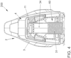
- FIG 4 The integration of the ventilation device 60 into a vehicle seat 2 is shown as an example.
- Figure 5 the ventilation device 60 with the air duct arrangement 30 is shown in a further perspective.
- a panel 42 can be connected to the ventilation device 60.
- this panel 42 can have a U-shaped air outlet for the air outlets 10. This also enables a space-saving integration of a folding table 43 into the Vehicle seat 2.
- the panel 42 can also be part of a fastening arrangement 40 in order to fasten the ventilation device 60 to the vehicle seat 2.
- FIG. 7 and 8th A control arrangement 50 for a ventilation device 60 according to the invention is shown schematically.
- at least one first servomotor 51 can be provided for opening and/or closing air outlet areas of the at least one side air outlet 11.
- the at least one first servomotor 51 can be in mechanical operative connection with a flow mechanism 13, e.g. B. with a closure 13 of the at least one side air outlet 11.
- At least a second servomotor 52 can also be used to move at least one slat 14 of the central air outlet 12 in order to adjust a flow direction.
- a flow grille 15 can also be arranged in front of at least one of the air outlets 10 (see Figure 9 ).
- At least a first slat 14a can be provided for horizontal and at least a second slat 14b for vertical adjustment of the air direction.
- FIG 10 schematically shows a seat shell 44 which is adapted to accommodate a ventilation device 60.
- the seat shell 44 can be used, for example.
- B. have at least one opening for receiving an air duct 34.
- cooling case 111 a directional spot can be generated in a first cooling case 111a.
- second cooling case 111b diffuse ventilation can be generated.
- the air is not heated, unlike in the heating cases 112, in which the air flow can be heated to a temperature that can be determined automatically and/or manually by the vehicle occupant 5.
- first heating case 112a warm air can be generated via foot vents 16 or an outlet in the lower back panel 4.
- the ventilation device 60 can be operated to produce an electric blanket.
- a defrost function can be provided in a third heating case 112c.
Description
Die vorliegende Erfindung betrifft eine Belüftungsvorrichtung gemäß der im Oberbegriff des Anspruchs 1 näher definierten Art.The present invention relates to a ventilation device according to the type defined in more detail in the preamble of
Es ist bekannt, verschiedene Klimatisierungsfunktionen in einem Fahrzeug zu nutzen. Solche Klimatisierungsfunktionen können z. B. Spot- und Diffusausströmungsfunktionen sein. Dabei ist es für die hinteren Sitzreihen im Fond des Fahrzeuges häufig nicht oder technisch nur sehr aufwendig möglich, diese Funktionen bereitzustellen. Problematisch sind dabei insbesondere Bauraumrestriktionen, durch welche die Integration der Klimatisierungsfunktionen für den hinteren Sitzbereich erschwert wird. Entsprechend stehen die Funktionen oft nur den vorderen Sitzreihen zur Verfügung.It is known to use various air conditioning functions in a vehicle. Such air conditioning functions can e.g. B. Spot and diffuse outflow functions. It is often not possible or only technically very complex to provide these functions for the rear rows of seats in the rear of the vehicle. Particularly problematic are the installation space restrictions, which make the integration of the air conditioning functions for the rear seating area more difficult. Accordingly, the functions are often only available to the front rows of seats.
Aus der
Die
Aus der
Es ist daher eine Aufgabe der vorliegenden Erfindung, die voranstehend beschriebenen Nachteile zumindest teilweise zu beheben. Insbesondere ist es eine Aufgabe der vorliegenden Erfindung, eine verbesserte Belüftungsvorrichtung bereitzustellen, welche in technisch einfacher und kostengünstiger Weise eine Bereitstellung verschiedener Klimatisierungsfunktionen für die hinteren Sitzreihen eines Fahrzeuges ermöglicht. Die voranstehende Aufgabe wird gelöst durch eine Belüftungsvorrichtung mit den Merkmalen des Anspruchs 1. Weitere Merkmale und Details der Erfindung ergeben sich aus den jeweiligen Unteransprüchen, der Beschreibung und den Zeichnungen. Dabei gelten Merkmale und Details, die im Zusammenhang mit der erfindungsgemäßen Belüftungsvorrichtung beschrieben sind.It is therefore an object of the present invention to at least partially eliminate the disadvantages described above. In particular, it is an object of the present invention to provide an improved ventilation device which enables various air conditioning functions for the rear rows of seats of a vehicle to be provided in a technically simple and cost-effective manner. The above object is achieved by a ventilation device with the features of
Die Aufgabe wird insbesondere gelöst durch eine Belüftungsvorrichtung zur Bereitstellung eines Luftstroms in einem Fahrzeug, mit einer Luftführungsanordnung, welche mit wenigstens drei Luftauslässen verbunden ist, um den Luftstrom an die Luftauslässe zu leiten.The object is achieved in particular by a ventilation device for providing an air flow in a vehicle, with an air guide arrangement which is connected to at least three air outlets in order to direct the air flow to the air outlets.
Die wenigstens drei Luftauslässe umfassen:
- einen zentralen Luftauslass zur (insbesondere zentralen) Integration in einen Fahrzeugsitz des Fahrzeuges, um eine gerichtete, d. h. richtbare (Spot-) Luftausströmung in einen Belüftungsbereich hinter dem Fahrzeugsitz, bevorzugt einem Fond, bereitzustellen,
- zwei seitliche Luftauslässe, welche zur Integration in den Fahrzeugsitz seitlich zum zentralen Luftauslass angeordnet sind, vorzugsweise in einen Randbereich des Fahrzeugsitzes, um eine diffuse Luftausströmung in den Belüftungsbereich bereitzustellen.
- a central air outlet for (in particular central) integration into a vehicle seat of the vehicle in order to provide a directed, ie directable (spot) air outflow into a ventilation area behind the vehicle seat, preferably a rear,
- two side air outlets, which are arranged laterally to the central air outlet for integration into the vehicle seat, preferably in an edge area of the vehicle seat, in order to provide a diffuse air outflow into the ventilation area.
Dies hat den Vorteil, dass zumindest zwei unterschiedliche Klimatisierungsfunktionen für die hinteren Sitzreihen in konstruktiv vereinfachter Weise bereitgestellt werden können, wie die diffuse Luftausströmung als eine erste Funktion und die gerichtete (richtbare) Luftausströmung als eine zweite Funktion. Ein besonderer Vorteil ergibt sich durch die Anordnung der seitlichen Luftauslässe seitlich zum zentralen Luftauslass, wodurch eine besonders platzsparende Integration im Fahrzeugsitz (insbesondere Vordersitz) möglich ist. Insbesondere bezieht sich hierbei die seitliche Anordnung auf eine Anordnung in einem Seitenbereich, welcher z. B. seitlich von einem gedachten geometrischen Schwer- bzw. Mittelpunkt des zentralen Luftauslasses liegt. In einem montierten Zustand der erfindungsgemäßen Belüftungsvorrichtung mit einem Fahrzeugsitz ergibt sich hierdurch eine Anordnung des wenigstens einen seitlichen Luftauslasses in wenigstens einem Außenbereich, insbesondere Randbereich (in Bezug auf die horizontale Fahrzeugrichtung) des Fahrzeugsitzes. Die zwei seitlichen Luftauslässe sind auf gegenüberliegenden Außenbereichen des Fahrzeugsitzes angeordnet, wobei sich der zentrale Luftauslass in einem oberen Mittelbereich zwischen diesen Außenbereichen erstreckt. Auf diese Weise ergibt sich, jedenfalls aus der Perspektive eines Fahrzeuginsassen auf einem Rücksitz hinter dem Fahrzeugsitz mit der erfindungsgemäßen Belüftungsvorrichtung, eine (umgedrehte) U-Form der Anordnung aus zentralen und seitlichen Luftauslässen.This has the advantage that at least two different air conditioning functions for the rear rows of seats can be provided in a structurally simplified manner, such as the diffuse air outflow as a first function and the directed (directional) air outflow as a second function. A particular advantage arises from the arrangement of the side air outlets to the side of the central air outlet, which enables particularly space-saving integration in the vehicle seat (particularly the front seat). In particular, the lateral arrangement here refers to an arrangement in a side area, which z. B. lies to the side of an imaginary geometric center of gravity or center of the central air outlet. In a mounted state of the ventilation device according to the invention with a vehicle seat, this results in an arrangement of the at least one side air outlet in at least one external area, in particular the edge region (with respect to the horizontal vehicle direction) of the vehicle seat. The two side air outlets are arranged on opposite outer areas of the vehicle seat, with the central air outlet extending in an upper central area between these outer areas. On This results in an (inverted) U-shape of the arrangement of central and side air outlets, at least from the perspective of a vehicle occupant in a back seat behind the vehicle seat with the ventilation device according to the invention.
Insbesondere ist es nachfolgend vorgesehen, dass Richtungsangaben stets in Bezug auf die Fahrzeugrichtungen zu verstehen sind. "Oben" bzw. "Unten" bezieht sich somit auf eine vertikale Fahrzeugachse (oder auch Fahrzeughochachse) und "Vorne", "Vorder" bzw. "Hinten", "Rück" auf eine Fahrzeuglängsachse (oder auch Fahrtrichtung) des Fahrzeuges sowie "links" bzw. "rechts" auf eine horizontale Fahrzeugachse (oder auch Fahrzeugquerachse). Das Fahrzeug ist bspw. als ein Kraftfahrzeug und/oder als ein Personenkraftfahrzeug und/oder als ein Elektrofahrzeug und/oder als ein Hybridfahrzeug ausgebildet.In particular, it is provided below that directional information is always to be understood in relation to the vehicle directions. “Top” or “bottom” therefore refers to a vertical vehicle axis (or vehicle vertical axis) and “front”, “front” or “rear”, “rear” refers to a vehicle longitudinal axis (or direction of travel) of the vehicle and “left " or "right" on a horizontal vehicle axis (or transverse vehicle axis). The vehicle is designed, for example, as a motor vehicle and/or as a passenger vehicle and/or as an electric vehicle and/or as a hybrid vehicle.
Die Luftführungsanordnung kann mit einer Luftquelle, z. B. einem Lüfter und/oder einer Klimaanlage des Fahrzeuges, verbunden sein, um den Luftstrom (als klimatisierten Luftstrom) zumindest teilweise von der Luftquelle bis zum jeweiligen Luftauslass zu leiten, sodass der Luftstrom dort in diffuser bzw. gerichteter Weise austritt. Um die Luftführung zu bewirken, kann die Luftführungsanordnung wenigstens einen Luftkanal aufweisen, z. B. ein Teleskoprohr und/oder ein Schlauchelement. Somit kann eine verbesserte Klimatisierung erzielt werden.The air duct arrangement can be connected to an air source, e.g. B. a fan and / or an air conditioning system of the vehicle, to direct the air flow (as a conditioned air flow) at least partially from the air source to the respective air outlet, so that the air flow emerges there in a diffuse or directed manner. In order to effect the air duct, the air duct arrangement can have at least one air duct, e.g. B. a telescopic tube and/or a hose element. Improved air conditioning can thus be achieved.
Es kann bei der erfindungsgemäßen Belüftungsvorrichtung von Vorteil sein, wenn der Belüftungsbereich, insbesondere ein rückseitiger Bereich hinter dem Fahrzeugsitz, in welchem die gerichtete Luftausströmung (Spotströmung) bzw. die diffuse Luftausströmung (Diffusströmung) bereitgestellt wird, dem Fondbereich des Fahrzeuges hinter den Vordersitzen entspricht. Somit kann die Luftausströmung für wenigstens einen Fahrgast (Fahrzeuginsassen) im Fond bereitgestellt werden, z. B. gerichtet auf wenigstens einen Rücksitz des Fahrzeuges. Des Weiteren ist es im Rahmen der Erfindung vorgesehen, dass eine Befestigungsanordnung zur Befestigung und/oder Anordnung und/oder Ausrichtung der Luftauslässe an einer Rückwand einer Rückenlehne des Fahrzeugsitzes, insbesondere eines Vordersitzes des Fahrzeuges, vorgesehen ist, um die Luftauslässe auf wenigstens einen Rücksitz des Fahrzeuges im Belüftungsbereich, vorzugsweise im Fond des Fahrzeuges, auszurichten und somit die jeweilige Luftausströmung für wenigstens einen Fahrzeuginsassen auf dem Rücksitz bereitzustellen. Hierzu kann die Befestigungsanordnung z. B. Fixierelemente (wie Schrauben oder dergleichen) und/oder wenigstens eine Führungsstange und/oder eine Blende und/oder dergleichen aufweisen, um die Belüftungsvorrichtung an den Fahrzeugsitz zu befestigen. Dies ermöglicht eine zuverlässige Integration in den Fahrzeugsitz, und insbesondere eine konstruktiv einfache Klimatisierung für den Belüftungsbereich im Fond des Fahrzeuges.It can be advantageous in the ventilation device according to the invention if the ventilation area, in particular a rear area behind the vehicle seat, in which the directed air outflow (spot flow) or the diffuse air outflow (diffuse flow) is provided, corresponds to the rear area of the vehicle behind the front seats. The air flow can thus be provided for at least one passenger (vehicle occupant) in the rear, e.g. B. directed at at least one back seat of the vehicle. Furthermore, it is provided within the scope of the invention that a fastening arrangement for fastening and / or arranging and / or aligning the air outlets on a rear wall of a backrest of the vehicle seat, in particular a front seat of the vehicle, is provided in order to attach the air outlets to at least one rear seat of the Vehicle in the ventilation area, preferably in the rear of the vehicle, to align and thus provide the respective air flow for at least one vehicle occupant in the back seat. For this purpose, the fastening arrangement can z. B. have fixing elements (such as screws or the like) and / or at least one guide rod and / or a cover and / or the like to attach the ventilation device to the vehicle seat. This enables reliable integration into the vehicle seat, and in particular a structurally simple air conditioning for the ventilation area in the rear of the vehicle.
Erfindungsgemäß sind die zwei seitlichen Luftauslässe auf unterschiedlichen Seiten gegenüberliegend zum zentralen Luftauslass angeordnet, und auf diesen gegenüberliegenden Seiten mit der Luftführungsanordnung verbunden, wobei der zentrale Luftauslass zwischen diesen Seiten mit der Luftführungsanordnung verbunden ist, um die Luftauslässe gemäß einer U-Form im Fahrzeugsitz anzuordnen. Von weiterem Vorteil kann die Anordnung der seitlichen Luftauslässe symmetrisch zum zentralen Luftauslass sein. Hierdurch kann eine besonders angenehme Anströmung der Fondpassagiere (symmetrisch zur Körpermitte) ermöglicht werden. Auch kann somit eine räumliche Anpassung für eine Anordnung eines Klapptisches am Fahrzeugsitz bereitgestellt werden. Bspw. ist der Klapptisch an der Rückenlehne (Backpanel) des Fahrzeugsitzes befestigt.According to the invention, the two side air outlets are arranged on different sides opposite the central air outlet, and are connected to the air duct arrangement on these opposite sides, the central air outlet being connected to the air duct arrangement between these sides in order to Arrange air outlets in a U-shape in the vehicle seat. A further advantage is that the arrangement of the side air outlets can be symmetrical to the central air outlet. This enables a particularly pleasant air flow for the rear passengers (symmetrical to the middle of the body). A spatial adjustment for arranging a folding table on the vehicle seat can also be provided. For example, the folding table is attached to the backrest (back panel) of the vehicle seat.
Des Weiteren können die seitlichen Luftauslässe und/oder der zentrale Luftauslass jeweils ggf. mit einem zentralen Luftkanal, insbesondere einer Verteilung für den Luftstrom, verbunden sein, sodass von dem zentralen Luftkanal die Luft zu den jeweiligen Luftauslässen geleitet werden kann. In diesem zentralen Luftkanal kann außerdem wenigstens eine Luftklappe integriert sein, um ein situatives Verschließen eines Luftauslasses zu ermöglichen. Die Verstellung dieser Luftklappe kann dabei bspw. manuell und/oder automatisiert und/oder elektrisch erfolgen. Dabei kann für jeden Luftauslass eine jeweils zugeordnete Luftklappe oder alternativ nur eine einzige Luftklappe für sämtliche Luftauslässe vorgesehen sein.Furthermore, the side air outlets and/or the central air outlet can each optionally be connected to a central air duct, in particular a distribution for the air flow, so that the air can be directed from the central air duct to the respective air outlets. At least one air flap can also be integrated into this central air duct in order to enable an air outlet to be closed depending on the situation. The adjustment of this air flap can be done, for example, manually and/or automatically and/or electrically. An assigned air flap can be provided for each air outlet or, alternatively, only a single air flap can be provided for all air outlets.
Auch kann es möglich sein, dass der zentrale Luftauslass als ein Spot-Ausströmer, insbesondere als ein Breitbandausströmer, ausgebildet ist. Dieser kann eine reduzierte Einbautiefe und eine Umlenkung aufweisen, um den Luftstrom zum Austreten aus der Ebene des Backpanels umzulenken. Insbesondere kann der zentrale Luftauslass einen Wirkbereich bis zur Seitenscheibe und/oder bis zum Fahrzeughimmel und/oder bis zum Bauch-Bereich der Fahrzeuginsassen im Fond abdecken.It may also be possible for the central air outlet to be designed as a spot vent, in particular as a broadband vent. This can have a reduced installation depth and a deflection to redirect the air flow to exit the plane of the back panel. In particular, the central air outlet can cover an effective area up to the side window and/or up to the vehicle headliner and/or up to the stomach area of the vehicle occupants in the rear.
Ferner kann es im Rahmen der Erfindung vorgesehen sein, dass eine Steuerungsanordnung vorgesehen ist, um einen Strömungsmechanismus des zentralen Luftauslasses anzusteuern, sodass vorzugsweise die Luftausströmung des zentralen Luftauslasses zwischen der gerichteten Luftausströmung und einer weiteren diffusen Luftausströmung umschaltbar ist. In anderen Worten kann der zentrale Luftauslass wahlweise eine Luftausströmung in gerichteter Weise (als Spotströmung) und in diffuser Weise bereitstellen, sodass durch den zentralen Luftauslass wie bei dem seitlichen Luftauslass die Strömung auch als diffuse Strömung ausgegeben werden kann. Damit kann ein Umschalten zwischen Klimatisierungsfunktionen durch die Steuerungsanordnung ermöglicht werden. Weiterhin können ggf. schaltbare Belüftungsstile (Spot-Diffus) bereitgestellt werden. Von Vorteil ist es ferner, wenn die Luftauslässe in Bezug auf die Ausströmungsmenge und/oder -richtung und/oder -art verstellbar ausgeführt sind, vorzugsweise elektrisch verstellbar, bevorzugt durch eine Steuerungsanordnung (bspw. als elektrische Richtungsverstellung).Furthermore, it can be provided within the scope of the invention that a control arrangement is provided in order to control a flow mechanism of the central air outlet, so that preferably the air outflow of the central air outlet can be switched between the directed air outflow and a further diffuse air outflow. In other words, the central air outlet can optionally provide an air outflow in a directed manner (as a spot flow) and in a diffuse manner, so that through the central air outlet, as with the side air outlet, the flow can also be output as a diffuse flow. This makes it possible to switch between air conditioning functions through the control arrangement. Furthermore, switchable ventilation styles (spot-diffuse) can be provided if necessary. It is also advantageous if the air outlets are designed to be adjustable in relation to the outflow quantity and/or direction and/or type, preferably electrically adjustable, preferably by a control arrangement (e.g. as an electrical direction adjustment).
Von Vorteil umfasst die Steuerungsanordnung eine Steuerungseinheit, wie eine Elektronik, insbesondere einen Mikrocontroller oder dergleichen, um eine elektrische Verstellung (bspw. Richtungsverstellung) bei wenigstens einem der Luftauslässe zu ermöglichen. Insbesondere kann durch die Steuerungsanordnung, bspw. durch wenigstens einen Stellmotor, eine Lamelle und/oder ein Verschluss eines jeweiligen Luftauslasses bewegt werden, um die Richtung der Luftströmung einfach und komfortabel zu verstellen. Die Bedienung der Steuerungsanordnung und/oder Richtungsverstellung kann bspw. über eine Eingabevorrichtung, wie ein Bedienteil einer Mittelkonsole, erfolgen. Auch kann die Ansteuerung der Steuerungsanordnung ggf. automatisiert erfolgen, um z. B. Klimatisierungsprofile, wie einen Sommer- und Winterbetrieb, bereitzustellen.The control arrangement advantageously comprises a control unit, such as electronics, in particular a microcontroller or the like, in order to enable electrical adjustment (e.g. directional adjustment) in at least one of the air outlets. In particular, a slat and/or a closure of a respective air outlet can be moved by the control arrangement, for example by at least one servomotor, in order to adjust the direction of the air flow easily and conveniently. The control arrangement and/or direction adjustment can be operated, for example, via an input device, such as a control panel on a center console. The control arrangement can also be activated automatically if necessary, for example. B. To provide air conditioning profiles, such as summer and winter operation.
Erfindungsgemäß ist die Luftführungsanordnung längsbeweglich in einer Befestigungsanordnung angeordnet und/oder geführt, sodass die Luftführungsanordnung (insbesondere in Bezug auf eine Längsrichtung des Fahrzeuges) längsverstellbar ausgeführt ist. Damit wird eine Anpassung an eine variierende Sitzposition möglich. Insbesondere ist hierzu die Luftführungsanordnung zumindest längsbeweglich, also zumindest in Längsrichtung und ggf. in weiteren Richtungen beweglich, durch die Befestigungsanordnung geführt und/oder gelagert. Alternativ oder zusätzlich kann die Luftführungsanordnung dadurch längsverstellbar ausgebildet sein, dass die Luftführungsanordnung wenigstens ein (hinsichtlich der Länge) flexibles Element aufweist, insbesondere eine Teleskopstange und/oder ein Schlauchelement und/oder dergleichen.According to the invention, the air duct arrangement is arranged and/or guided in a fastening arrangement in a longitudinally movable manner, so that the air duct arrangement is designed to be longitudinally adjustable (in particular with respect to a longitudinal direction of the vehicle). This makes it possible to adapt to a varying sitting position. In particular, for this purpose the air guide arrangement is at least longitudinally movable, i.e. movable at least in the longitudinal direction and possibly in further directions, guided and/or supported by the fastening arrangement. Alternatively or additionally, the air duct arrangement can be designed to be longitudinally adjustable in that the air duct arrangement has at least one (in terms of length) flexible element, in particular a telescopic rod and/or a hose element and/or the like.
Vorteilhaft ist es zudem, wenn die Luftführungsanordnung wenigstens einen flexiblen Luftkanal und/oder wenigstens ein Teleskoprohr und/oder wenigstens ein (flexibles und/oder elastisches) Schlauchelement zur Integration an oder im Fahrzeugsitz umfasst, um eine Anpassung an eine Verstellung des Fahrzeugsitzes im Fahrzeug durchzuführen. Hierbei bezieht sich die Verstellung vorteilhafterweise auf eine Verstellung der Sitzposition des Fahrzeugsitzes (z. B. in Fahrzeuglängsrichtung bzw. Fahrtrichtung) und/oder auf einen Verstellwinkel des Fahrzeugsitzes (also einen Verstellwinkel der Rückenlehne) und/oder auf eine Höhenverstellung des Fahrzeugsitzes. Somit kann ein entsprechendes Verstellfeld des Fahrzeugsitzes zuverlässig ausgeglichen werden. Bspw. umfasst das Teleskoprohr verschiedene Rohrsegmente, welche über Dichtlippen abgedichtet sind. Auch kann ein Schlauchelement, insbesondere ein Balg, aus einem flexiblen Material, wie Kunststoff, vorgesehen sein. Darüber hinaus können auch Führungselemente, wie eine Führungsstange, zur Steigerung der Stabilität beim Verfahren des Fahrzeugsitzes für die erfindungsgemäße Belüftungsvorrichtung genutzt werden. Eine Befestigungsanordnung kann vorgesehen sein, um eine Fixierung von Teilen der Belüftungsvorrichtung, insbesondere der Luftführungsanordnung, an die Sitzstruktur zu ermöglichen. Durch das Schlauchelement kann ferner eine Umlenkung der Luftführungsanordnung erfolgen, um einen Aufgang in die Rücklehne des Fahrzeugsitzes und die Anpassung an den Verstellwinkel zu berücksichtigen. Das Schlauchelement kann dabei auch als Gelenkrohr oder Vielgelenk oder dergleichen ausgebildet sein und/oder mit einem luftdichten Schlauch oder Textil umhüllt sein.It is also advantageous if the air duct arrangement comprises at least one flexible air duct and/or at least one telescopic tube and/or at least one (flexible and/or elastic) hose element for integration on or in the vehicle seat in order to adapt to an adjustment of the vehicle seat in the vehicle . Here, the adjustment advantageously relates to an adjustment of the seating position of the vehicle seat (e.g. in the longitudinal direction of the vehicle or direction of travel) and/or to an adjustment angle of the vehicle seat (i.e. an adjustment angle of the backrest) and/or to a height adjustment of the vehicle seat. A corresponding adjustment field of the vehicle seat can therefore be reliably compensated for. For example, the telescopic tube comprises various tube segments which are sealed via sealing lips. A hose element, in particular a bellows, made of a flexible material, such as plastic, can also be provided. In addition, guide elements, such as a guide rod, can also be used to increase stability when moving the vehicle seat for the ventilation device according to the invention. A fastening arrangement can be provided to enable parts of the ventilation device, in particular the air duct arrangement, to be fixed to the seat structure. The hose element can also provide a deflection of the air duct arrangement in order to take into account a rise into the backrest of the vehicle seat and the adjustment to the adjustment angle. The hose element can also be designed as an articulated tube or multi-joint or the like and/or can be covered with an airtight hose or textile.
Erfindungsgemäß ist wenigstens eine Lamelle im Auslassbereich des zentralen Luftauslasses und/oder der seitlichen Luftauslässe beweglich gelagert, um den Luftstrom aus dem Auslassbereich einzustellen. Hierbei kann die Verwendung von einer oder mehreren Lamellen (z. B. horizontale und/oder vertikale Lamellen) eine Verstellung des Luftstroms in horizontaler bzw. vertikaler Fahrzeugrichtung bewirken. Z. B. kann hierbei die wenigstens eine Lamelle in einer Blende, z. B. einer Zierblende zur Verdeckung der eigentlichen Ausströmfunktion, integriert sein. Es kann dabei vorteilhaft sein, wenn die wenigstens eine Lamelle zur Verstellung in vertikaler Fahrzeugrichtung und/oder wenn die wenigstens eine Lamelle zur Verstellung in horizontaler Fahrzeugrichtung sich manuell oder elektrisch verstellen lässt, z. B. über einen zentralen Reiter und/oder über entsprechende Stellmotoren.According to the invention, at least one slat is movably mounted in the outlet area of the central air outlet and/or the side air outlets in order to adjust the air flow from the outlet area. The use of one or more slats (e.g. horizontal and/or vertical slats) can cause the air flow to be adjusted in the horizontal or vertical direction of the vehicle. For example, the at least one slat can be in a panel, e.g. B. a decorative panel to conceal the actual outflow function. It can be advantageous if the at least one slat for adjustment in the vertical vehicle direction and / or if the at least one slat for adjustment in the horizontal vehicle direction can be adjusted manually or electrically, e.g. B. via a central rider and/or via appropriate servomotors.
Es ist weiter optional möglich, dass eine Steuerungsanordnung vorgesehen ist, um wenigstens einen Verschluss, vorzugsweise wenigstens eine Lamelle, für wenigstens einen der Luftauslässe zu verstellen. Die Steuerungsanordnung kann dazu wenigstens einen elektrischen Motor, insbesondere Stellmotor, umfassen, welcher zur Übertragung einer Bewegung mit dem Verschluss in mechanischer Verbindung steht. Damit ist eine einfache und zuverlässige Luftregulation möglich.It is also optionally possible for a control arrangement to be provided in order to adjust at least one closure, preferably at least one slat, for at least one of the air outlets. For this purpose, the control arrangement can comprise at least one electric motor, in particular a servomotor, which is in mechanical connection with the closure in order to transmit a movement. This enables simple and reliable air regulation.
Insbesondere dienen die seitlichen Luftauslässe als Diffus-Ausströmer im seitlichen Bereich des Backpanels dazu, einen Luftstrom mit reduzierter Strömungsgeschwindigkeit der Luft bei großem Querschnitt des Luftauslasses bereitzustellen. Vorteilhafterweise ist dabei der Querschnitt für den Luftaustritt beim jeweiligen seitlichen Luftauslass größer als bei dem zentralen Luftauslass, z. B. mindestens zweifach so groß. Insbesondere kann ein Gitter, wie ein Kunststoff- oder Metallgitter, an dem seitlichen Luftauslass angeordnet, insbesondere befestigt, sein. Hierbei kann das Gitter eine Vorzugsrichtung zum Richten des Luftstroms aufweisen. Eine diffuse Strömung ermöglicht hierbei, dass keine direkte Anströmung der Beine und/oder des Oberkörpers der hinteren Fahrzeuginsassen erfolgt (diffuse Luftverteilung bei reduziertem Zugempfinden). Ferner kann auch eine Kombination der Strömungsfunktion der seitlichen Luftauslässe mit einem gedrosselten Luftstrom aus einem zentralen Luftauslass möglich sein, um eine U-förmige diffuse Ausströmfläche zu erhalten.In particular, the side air outlets serve as diffuse vents in the side area of the back panel to provide an air flow with a reduced air flow speed with a large cross section of the air outlet. Advantageously, the cross section for the air outlet at the respective side air outlet is larger than at the central air outlet, e.g. B. at least twice as large. In particular, a grille, such as a plastic or metal grille, can be arranged, in particular attached, to the side air outlet. The grid can have a preferred direction for directing the air flow. A diffuse flow ensures that there is no direct flow against the legs and/or upper body of the rear vehicle occupants (diffuse air distribution with reduced draft sensation). Furthermore, a combination of the flow function of the side air outlets with a throttled air flow from a central one can also be used Air outlet may be possible to obtain a U-shaped diffuse outflow surface.
Außerdem kann es im Rahmen der Erfindung von Vorteil sein, dass wenigstens zwei Fahrzeugsitze in einem Fahrzeug vorgesehen sind, und jeweils ein zentraler Luftauslass und jeweils zwei seitliche Luftauslässe an einer jeweiligen Rückwand einer jeweiligen Rückenlehne der jeweiligen Fahrzeugsitze, insbesondere Vordersitze des Fahrzeuges, befestigt sind. Damit ist eine besonders effiziente Fahrzeugklimatisierung möglich.In addition, it can be advantageous within the scope of the invention that at least two vehicle seats are provided in a vehicle, and a central air outlet and two side air outlets are attached to a respective rear wall of a respective backrest of the respective vehicle seats, in particular front seats of the vehicle. This makes particularly efficient vehicle air conditioning possible.
Erfindungsgemäß ist der zentrale Luftauslass (z. B. in Bezug auf eine Fahrzeugquerachse und/oder eine Ebene des Backpanels) zwischen den seitlichen Luftauslässen angeordnet, sodass in der Ebene des Backpanels eine (umgedrehte) U-Form ausgebildet wird. Bevorzugt ist dabei der zentrale Luftauslass mittig und/oder in einem oberen Bereich des Backpanels (d. h. der Rückenlehne des Fahrzeugsitzes) angeordnet.According to the invention, the central air outlet (e.g. in relation to a vehicle transverse axis and/or a plane of the back panel) is arranged between the side air outlets, so that an (inverted) U-shape is formed in the plane of the back panel. The central air outlet is preferably arranged in the middle and/or in an upper region of the back panel (i.e. the backrest of the vehicle seat).
Es kann bei dem Belüftungssystem gemäß einem weiteren Vorteil möglich sein, dass die Luftführungsanordnung zumindest teilweise, bspw. wenigstens ein Luftkanal der Luftführungsanordnung, in eine Sitzstruktur und/oder in das Backpanel (der Rückwand) des Fahrzeugsitzes, vorzugsweise Vordersitzes, integriert ist. Bspw. kann hierzu der Luftkanal abgehend von einer Mittelkonsole des Fahrzeuges im Fahrzeugsitz integriert sein. Besonders bevorzugt ist die Luftführungsanordnung dazu ausgeführt, das gesamte Verstellfeld des Fahrzeugsitzes, z. B. als verstellbarer Vordersitz, zu kompensieren. Dies kann durch eine Ausbildung der Luftführungsanordnung mit einer anpassbaren und/oder flexiblen Struktur, z. B. mit einem Teleskoprohr und/oder Schlauchelement, erzielt werden.In the ventilation system according to a further advantage, it may be possible for the air duct arrangement to be at least partially integrated, for example at least one air duct of the air duct arrangement, into a seat structure and/or into the back panel (the rear wall) of the vehicle seat, preferably the front seat. For example, the air duct can be integrated into the vehicle seat starting from a center console of the vehicle. The air duct arrangement is particularly preferably designed to cover the entire adjustment field of the vehicle seat, e.g. B. as an adjustable front seat to compensate. This can be achieved by designing the air duct arrangement with an adaptable and/or flexible structure, e.g. B. can be achieved with a telescopic tube and/or hose element.
Es ist weiter denkbar, dass die Luftauslässe jeweils als Ausströmer mit einer Ausströmfläche (d. h. einem Auslassbereich) ausgebildet sind, welche in die Rückseite des Fahrzeugsitzes integriert sind. Bevorzugt sind dabei die Luftauslässe (in Bezug auf die Auslassbereiche) derart ausgerichtet, dass ein Luftstrom aus den jeweiligen Luftauslässen in den hinteren Bereich (Fondbereich) geleitet wird.It is also conceivable that the air outlets are each designed as vents with an outflow surface (i.e. an outlet area), which are integrated into the back of the vehicle seat. The air outlets are preferably aligned (in relation to the outlet areas) in such a way that an air flow is directed from the respective air outlets into the rear area (rear area).
Darüber hinaus kann es von Vorteil sein, wenn wenigstens ein Lichtelement, insbesondere wenigstens eine Leuchtdiode, bei dem Belüftungssystem vorgesehen ist und z. B. in einer Blende angeordnet oder an dieser befestigt ist. Hierdurch kann bspw. in Abhängigkeit von einer Klimatisierungsfunktion, z. B. einer Heizfunktion oder einer Kühlfunktion, eine unterschiedliche Beleuchtung, bspw. mit unterschiedlichen Farben, erfolgen.In addition, it can be advantageous if at least one light element, in particular at least one light-emitting diode, is provided in the ventilation system and, for. B. is arranged in a panel or attached to it. This allows, for example, depending on an air conditioning function, e.g. B. a heating function or a cooling function, different lighting, for example with different colors.
Weitere Vorteile, Merkmale und Einzelheiten der Erfindung ergeben sich aus der nachfolgenden Beschreibung, in der unter Bezugnahme auf die Zeichnungen Ausführungsbeispiele der Erfindung im Einzelnen beschrieben sind.Further advantages, features and details of the invention emerge from the following description, in which exemplary embodiments of the invention are described in detail with reference to the drawings.
Es zeigen jeweils schematisch:
- Fig. 1
- eine perspektivische Darstellung eines Belüftungssystems,
- Fig. 2
- eine Ansicht aus der Perspektive eines Fahrzeuginsassen im rückseitigen Fondbereich des Fahrzeuges,
- Fig. 3 bis 9
- perspektivische Darstellungen von Teilen einer erfindungsgemäßen Belüftungsvorrichtung eines Belüftungssystems
- Fig. 10
- eine perspektivische Darstellung einer Sitzschale eines Fahrzeugsitzes,
- Fig. 11
bis 15 - Darstellungen verschiedener Klimatisierungsfunktionen.
- Fig. 1
- a perspective view of a ventilation system,
- Fig. 2
- a view from the perspective of a vehicle occupant in the rear rear area of the vehicle,
- Fig. 3 to 9
- Perspective representations of parts of a ventilation device according to the invention of a ventilation system
- Fig. 10
- a perspective view of a seat shell of a vehicle seat,
- Fig. 11 to 15
- Representations of various air conditioning functions.
In
In
Des Weiteren ist in
In
In
In
In den
Die voranstehende Erläuterung der Ausführungsformen beschreibt die vorliegende Erfindung ausschließlich im Rahmen von Beispielen.The above explanation of the embodiments describes the present invention solely in terms of examples.
- 11
- Fahrzeugvehicle
- 22
- FahrzeugsitzVehicle seat
- 2a2a
- VordersitzFront seat
- 2b2 B
- Rücksitzback seat
- 33
- Rückenlehnebackrest
- 44
- Rückwand, Backpanel, Rückwand RückenlehneBack wall, back panel, back wall backrest
- 55
- Fahrzeuginsassevehicle occupant
- 66
- Belüftungsbereich, rückseitiger Bereich, FondVentilation area, rear area, rear
- 7a7a
- erste Seitefirst page
- 7b7b
- zweite Seitesecond page
- 1010
- LuftauslassAir outlet
- 1111
- seitlicher Luftauslass, für Diffus-AusströmerSide air outlet, for diffuse vents
- 11a11a
- erster seitlicher Luftauslassfirst side air outlet
- 11b11b
- zweiter seitlicher Luftauslasssecond side air outlet
- 1212
- zentraler Luftauslass, für Spot-Ausströmercentral air outlet, for spot vents
- 1313
- Strömungsmechanismus, Verschluss, zum Verschließen der Diffus-BereicheFlow mechanism, closure, to close the diffuse areas
- 14a14a
- erste Lamelle(n), für das horizontale Justieren der Strömungsrichtungfirst slat(s), for horizontal adjustment of the flow direction
- 14b14b
- zweite Lamelle(n), für das vertikale Justieren der Strömungsrichtungsecond slat(s), for vertical adjustment of the flow direction
- 1515
- StrömungsgitterFlow grid
- 1616
- FußausströmerFoot air vents
- 2020
- Spotströmung, gerichtete LuftausströmungSpot flow, directed air flow
- 2121
- Diffusströmung, diffuse LuftausströmungDiffuse flow, diffuse air outflow
- 2525
- EingabevorrichtungInput device
- 3030
- Luftführungsanordnung, LuftkanalanordnungAir duct arrangement, air duct arrangement
- 3131
- Schlauchelement, BalgHose element, bellows
- 3232
- TeleskoprohrTelescopic tube
- 3333
- Luftzufuhr, (aus Front- oder Mittelkonsolenklimagerät)Air supply (from front or center console air conditioning unit)
- 3434
- Luftkanal, VerteilungAir duct, distribution
- 4040
- BefestigungsanordnungFastening arrangement
- 4141
- FührungsstangeGuide rod
- 4242
- Blendecover
- 4343
- Klapptischfolding table
- 4444
- SitzschaleSeat shell
- 5050
- SteuerungsanordnungControl arrangement
- 5151
- erster Stellmotor, für 13, für Verschließen/Öffnen der Diffus-Bereichefirst servomotor, for 13, for closing/opening the diffuse areas
- 5252
- zweiter Stellmotor, für 14, für Bewegung der Lamellen der Spot-Ausströmersecond servomotor, for 14, for moving the slats of the spot vents
- 6060
- BelüftungsvorrichtungVentilation device
- 111111
- KühlfallCooling case
- 111a111a
- erster Kühlfall zur Erzeugung eines richtbaren Spotsfirst cooling case to create a directional spot
- 111b111b
- zweiter Kühlfall zur Erzeugung einer diffusen Belüftungsecond cooling case to create diffuse ventilation
- 112112
- HeizfallHeating case
- 112a112a
- erster Heizfall zur Erzeugung von Warmluft über Fußausströmer oder Auslass im unteren BackpanelFirst heating case to generate warm air via foot vents or outlet in the lower back panel
- 112b112b
- zweiter Heizfall zur Erzeugung einer Heizdeckesecond heating case to create an electric blanket
- 112c112c
- dritter Heizfall zur Bereitstellung einer Defrost-Funktionthird heating case to provide a defrost function
- 200200
- BelüftungssystemVentilation system
Claims (5)
- Ventilation device (60) for providing an air flow in a vehicle (1), wherein the ventilation device comprises an air-guiding arrangement (30) which is connected to at least three air outlets (10, 12) in order to direct the air flow to the air outlets (10, 12), and wherein the ventilation device comprises a vehicle seat (2) and a fastening arrangement (40) fastened to the vehicle seat (2), wherein the at least three air outlets (10, 12) comprise:- a central air outlet (12) for integrating in a vehicle seat (2) of the vehicle (1) in order to provide a directed air outflow (20) into a ventilation region (6) behind the vehicle seat (2),- two lateral air outlets (11a, 11b) which, for integrating in the vehicle seat (2), are arranged laterally with respect to the central air outlet (12) in order to provide a diffuse air outflow (21) into the ventilation region (6), wherein at least one slat (14) is mounted movably in the outlet region of the central air outlet (12) and/or of the lateral air outlets (11a, 11b) in order to adjust the air flow from the outlet region, wherein the two lateral air outlets (11a, 11b) are arranged on different sides (7a, 7b) opposite the central air outlet (12) and are connected on these opposite sides (7a, 7b) to the air-guiding arrangement (30), wherein the central air outlet (10) is connected between these sides (7a, 7b) to the air-guiding arrangement (30) in order to arrange the air outlets (11a, 11b, 12) in the vehicle seat (2) in accordance with a U shape, characterized in that a part of the air-guiding arrangement (30) is guided in a longitudinally movable manner in the fastening arrangement (40), which is fastened to the vehicle seat (2), and therefore the part of the air-guiding arrangement (30) is designed to be longitudinally adjustable relative to the vehicle seat (2) .
- Ventilation device (60) according to Claim 1, characterized in that the fastening arrangement (40) is provided for fastening the air outlets (10) to a rear wall (4) of a backrest (3) of the vehicle seat (2), in particular a front seat (2a) of the vehicle (1), in order to align the air outlets (10, 12) on at least one rear seat (2b) of the vehicle (1) in the ventilation region (6), preferably in the rear (6) of the vehicle (1), and thus to provide the respective air outflow (20, 21) for at least one vehicle occupant (5) on the rear seat (2b).
- Ventilation device (60) according to either of the preceding claims, characterized in that a control arrangement (50) is provided in order to activate a flow mechanism (13) of the central air outlet (12) such that the air outflow (20) of the central air outlet (12) can be switched over between the directed air outflow (20) and a further diffuse air outflow (20).
- Ventilation device (60) according to one of the preceding claims, characterized in that the air-guiding arrangement (30) comprises at least one flexible air duct (34) and/or at least one telescopic tube (32) and/or at least one hose element (31) for integrating on or in the vehicle seat (2) in order to carry out an adaptation to an adjustment of the vehicle seat (2) in the vehicle (1).
- Vehicle, characterized in that it comprises at least two ventilation devices (60) according to one of Claims 1 to 4.
Applications Claiming Priority (2)
| Application Number | Priority Date | Filing Date | Title |
|---|---|---|---|
| DE102017121423.2A DE102017121423A1 (en) | 2017-09-15 | 2017-09-15 | Ventilation device for a vehicle |
| PCT/EP2018/074932 WO2019053211A1 (en) | 2017-09-15 | 2018-09-14 | Ventilation device for a vehicle |
Publications (2)
| Publication Number | Publication Date |
|---|---|
| EP3681758A1 EP3681758A1 (en) | 2020-07-22 |
| EP3681758B1 true EP3681758B1 (en) | 2023-12-27 |
Family
ID=63708299
Family Applications (1)
| Application Number | Title | Priority Date | Filing Date |
|---|---|---|---|
| EP18779250.2A Active EP3681758B1 (en) | 2017-09-15 | 2018-09-14 | Ventilation device for a vehicle |
Country Status (3)
| Country | Link |
|---|---|
| EP (1) | EP3681758B1 (en) |
| DE (1) | DE102017121423A1 (en) |
| WO (1) | WO2019053211A1 (en) |
Citations (1)
| Publication number | Priority date | Publication date | Assignee | Title |
|---|---|---|---|---|
| DE102015100309A1 (en) * | 2014-01-13 | 2015-07-16 | GM Global Technology Operations LLC (n. d. Gesetzen des Staates Delaware) | Systems for improving climate comfort for vehicle-occupant passengers |
Family Cites Families (13)
| Publication number | Priority date | Publication date | Assignee | Title |
|---|---|---|---|---|
| IT1232900B (en) * | 1989-08-04 | 1992-03-05 | Fiat Auto Spa | SEAT FOR VEHICLES WITH AIR CONDITIONING |
| DE10054009B4 (en) * | 2000-11-01 | 2005-01-05 | Daimlerchrysler Ag | Wind protection device for an open motor vehicle |
| FR2843916B1 (en) * | 2002-09-02 | 2006-02-17 | Valeo Climatisation | THERMAL CONTROL DEVICE FOR A MOTOR VEHICLE |
| US20050087325A1 (en) * | 2003-10-27 | 2005-04-28 | Tim Roland | Air conditioning apparatus for rear seat arrangement |
| JP2006131106A (en) * | 2004-11-05 | 2006-05-25 | Denso Corp | Air-conditioner for vehicle |
| DE102006016091B4 (en) * | 2006-04-04 | 2009-10-01 | Johnson Controls Gmbh | Vehicle seat with an air outlet opening on the back of the backrest part |
| DE102009043112A1 (en) | 2009-09-25 | 2010-04-29 | Daimler Ag | Vehicle seat i.e. front seat, for passenger compartment of e.g. electric vehicle, has ventilation device with heating element for heating air stream, where air stream is applied into region behind seat over air exhaust opening |
| JP6094373B2 (en) * | 2012-10-29 | 2017-03-15 | 株式会社デンソー | Convection promotion device for vehicles |
| CN202981070U (en) * | 2012-12-29 | 2013-06-12 | 泰铂(上海)实业有限公司 | Seat for air conditioner indoor unit |
| DE102014223233A1 (en) | 2014-11-13 | 2016-05-19 | Volkswagen Aktiengesellschaft | Air conditioning device for a motor vehicle |
| JP6376282B2 (en) * | 2015-04-02 | 2018-08-22 | 株式会社デンソー | Vehicle seat air conditioning unit |
| EP3144180B1 (en) * | 2015-09-08 | 2017-09-20 | Denso Automotive Deutschland GmbH | Ventilation device and seat with such a ventilation device, in particular for a vehicle |
| JP2017154617A (en) * | 2016-03-02 | 2017-09-07 | 株式会社デンソー | Vehicle seat air conditioner |
-
2017
- 2017-09-15 DE DE102017121423.2A patent/DE102017121423A1/en active Pending
-
2018
- 2018-09-14 WO PCT/EP2018/074932 patent/WO2019053211A1/en unknown
- 2018-09-14 EP EP18779250.2A patent/EP3681758B1/en active Active
Patent Citations (1)
| Publication number | Priority date | Publication date | Assignee | Title |
|---|---|---|---|---|
| DE102015100309A1 (en) * | 2014-01-13 | 2015-07-16 | GM Global Technology Operations LLC (n. d. Gesetzen des Staates Delaware) | Systems for improving climate comfort for vehicle-occupant passengers |
Also Published As
| Publication number | Publication date |
|---|---|
| DE102017121423A1 (en) | 2019-03-21 |
| EP3681758A1 (en) | 2020-07-22 |
| WO2019053211A1 (en) | 2019-03-21 |
Similar Documents
| Publication | Publication Date | Title |
|---|---|---|
| DE10054008B4 (en) | Automobile seat | |
| DE2813909C2 (en) | Instrument panel for automobiles | |
| EP3765320B1 (en) | Ventilation device for the inside of a motor vehicle | |
| DE19908502C1 (en) | Open topped automobile such as a cabriolet or roadster with an integral heating system | |
| DE102017102214A1 (en) | INTEGRATED COOLING SYSTEM FOR AN ADJUSTABLE HEADREST ASSEMBLY | |
| EP3028894A1 (en) | Air conditioner for a motor vehicle | |
| DE102014118116A1 (en) | Device of a HVAC system for vehicles | |
| DE102016117443A1 (en) | Seat with a ventilation device and method for air conditioning the seating environment | |
| WO2020187466A1 (en) | Motor vehicle having a ventilation device having a plurality of separate air vents | |
| DE10242805A1 (en) | Internal ventilation system for road vehicle has plate with several holes set in roof lining and has gap round edge of central plate to allow radial escape of ventilating air | |
| EP1762406B1 (en) | Vehicle with a ventilation system for the windows and seats | |
| DE102012108962B4 (en) | Passenger supply unit for land, air and water vehicles | |
| EP3144180B1 (en) | Ventilation device and seat with such a ventilation device, in particular for a vehicle | |
| EP3681758B1 (en) | Ventilation device for a vehicle | |
| DE102017003289A1 (en) | Ventilation arrangement with movable defroster and interior ventilation nozzle | |
| DE102006031260A1 (en) | Vehicle seat, especially for a convertible automobile, has openings in the backrest to deliver a flow of warm air at the occupant's neck | |
| DE102015101970B4 (en) | Ventilation device for a vehicle dashboard | |
| EP3941768B1 (en) | Motor vehicle | |
| DE10353823B4 (en) | Ventilation device for a vehicle interior of a vehicle, in particular a commercial vehicle | |
| DE102016211486B4 (en) | Motor vehicle ventilation device | |
| DE102011003432A1 (en) | Vents for a ventilation system of a vehicle | |
| DE102019203471B4 (en) | Motor vehicle | |
| EP1213171A2 (en) | Wind barrier device for open vehicles | |
| DE19854537B4 (en) | Ventilation device for vehicles | |
| WO2020126919A1 (en) | Interior device for a motor vehicle |
Legal Events
| Date | Code | Title | Description |
|---|---|---|---|
| STAA | Information on the status of an ep patent application or granted ep patent |
Free format text: STATUS: UNKNOWN |
|
| STAA | Information on the status of an ep patent application or granted ep patent |
Free format text: STATUS: THE INTERNATIONAL PUBLICATION HAS BEEN MADE |
|
| PUAI | Public reference made under article 153(3) epc to a published international application that has entered the european phase |
Free format text: ORIGINAL CODE: 0009012 |
|
| STAA | Information on the status of an ep patent application or granted ep patent |
Free format text: STATUS: REQUEST FOR EXAMINATION WAS MADE |
|
| 17P | Request for examination filed |
Effective date: 20200415 |
|
| AK | Designated contracting states |
Kind code of ref document: A1 Designated state(s): AL AT BE BG CH CY CZ DE DK EE ES FI FR GB GR HR HU IE IS IT LI LT LU LV MC MK MT NL NO PL PT RO RS SE SI SK SM TR |
|
| AX | Request for extension of the european patent |
Extension state: BA ME |
|
| DAV | Request for validation of the european patent (deleted) | ||
| DAX | Request for extension of the european patent (deleted) | ||
| STAA | Information on the status of an ep patent application or granted ep patent |
Free format text: STATUS: EXAMINATION IS IN PROGRESS |
|
| 17Q | First examination report despatched |
Effective date: 20210408 |
|
| GRAP | Despatch of communication of intention to grant a patent |
Free format text: ORIGINAL CODE: EPIDOSNIGR1 |
|
| STAA | Information on the status of an ep patent application or granted ep patent |
Free format text: STATUS: GRANT OF PATENT IS INTENDED |
|
| INTG | Intention to grant announced |
Effective date: 20230718 |
|
| GRAS | Grant fee paid |
Free format text: ORIGINAL CODE: EPIDOSNIGR3 |
|
| GRAA | (expected) grant |
Free format text: ORIGINAL CODE: 0009210 |
|
| STAA | Information on the status of an ep patent application or granted ep patent |
Free format text: STATUS: THE PATENT HAS BEEN GRANTED |
|
| AK | Designated contracting states |
Kind code of ref document: B1 Designated state(s): AL AT BE BG CH CY CZ DE DK EE ES FI FR GB GR HR HU IE IS IT LI LT LU LV MC MK MT NL NO PL PT RO RS SE SI SK SM TR |
|
| REG | Reference to a national code |
Ref country code: GB Ref legal event code: FG4D Free format text: NOT ENGLISH |
|
| REG | Reference to a national code |
Ref country code: CH Ref legal event code: EP |
|
| REG | Reference to a national code |
Ref country code: DE Ref legal event code: R096 Ref document number: 502018013882 Country of ref document: DE |
|
| REG | Reference to a national code |
Ref country code: IE Ref legal event code: FG4D Free format text: LANGUAGE OF EP DOCUMENT: GERMAN |
|
| P01 | Opt-out of the competence of the unified patent court (upc) registered |
Effective date: 20231222 |
|
| PG25 | Lapsed in a contracting state [announced via postgrant information from national office to epo] |
Ref country code: GR Free format text: LAPSE BECAUSE OF FAILURE TO SUBMIT A TRANSLATION OF THE DESCRIPTION OR TO PAY THE FEE WITHIN THE PRESCRIBED TIME-LIMIT Effective date: 20240328 |
|
| REG | Reference to a national code |
Ref country code: LT Ref legal event code: MG9D |
|
| PG25 | Lapsed in a contracting state [announced via postgrant information from national office to epo] |
Ref country code: LT Free format text: LAPSE BECAUSE OF FAILURE TO SUBMIT A TRANSLATION OF THE DESCRIPTION OR TO PAY THE FEE WITHIN THE PRESCRIBED TIME-LIMIT Effective date: 20231227 |