EP3681328B1 - Casque de protection - Google Patents
Casque de protection Download PDFInfo
- Publication number
- EP3681328B1 EP3681328B1 EP18766268.9A EP18766268A EP3681328B1 EP 3681328 B1 EP3681328 B1 EP 3681328B1 EP 18766268 A EP18766268 A EP 18766268A EP 3681328 B1 EP3681328 B1 EP 3681328B1
- Authority
- EP
- European Patent Office
- Prior art keywords
- visor
- protrusion
- receiving seat
- protective helmet
- outer shell
- Prior art date
- Legal status (The legal status is an assumption and is not a legal conclusion. Google has not performed a legal analysis and makes no representation as to the accuracy of the status listed.)
- Active
Links
- 230000001681 protective effect Effects 0.000 title claims description 37
- 239000000463 material Substances 0.000 claims description 15
- 230000007246 mechanism Effects 0.000 claims description 12
- 230000000903 blocking effect Effects 0.000 claims description 8
- 238000007373 indentation Methods 0.000 claims description 2
- 238000012360 testing method Methods 0.000 description 12
- 210000003128 head Anatomy 0.000 description 6
- 230000001133 acceleration Effects 0.000 description 5
- 230000000694 effects Effects 0.000 description 5
- 229920006346 thermoplastic polyester elastomer Polymers 0.000 description 5
- 230000000295 complement effect Effects 0.000 description 4
- 239000004433 Thermoplastic polyurethane Substances 0.000 description 3
- 230000008901 benefit Effects 0.000 description 3
- 230000008878 coupling Effects 0.000 description 3
- 238000010168 coupling process Methods 0.000 description 3
- 238000005859 coupling reaction Methods 0.000 description 3
- 229920001169 thermoplastic Polymers 0.000 description 3
- 229920002725 thermoplastic elastomer Polymers 0.000 description 3
- 229920002803 thermoplastic polyurethane Polymers 0.000 description 3
- 239000004416 thermosoftening plastic Substances 0.000 description 3
- 230000009471 action Effects 0.000 description 2
- 230000001464 adherent effect Effects 0.000 description 2
- 239000013013 elastic material Substances 0.000 description 2
- 238000003780 insertion Methods 0.000 description 2
- 230000037431 insertion Effects 0.000 description 2
- 239000012815 thermoplastic material Substances 0.000 description 2
- 239000004677 Nylon Substances 0.000 description 1
- 208000034530 PLAA-associated neurodevelopmental disease Diseases 0.000 description 1
- 239000004743 Polypropylene Substances 0.000 description 1
- 230000003466 anti-cipated effect Effects 0.000 description 1
- 230000006931 brain damage Effects 0.000 description 1
- 231100000874 brain damage Toxicity 0.000 description 1
- 208000029028 brain injury Diseases 0.000 description 1
- 238000004140 cleaning Methods 0.000 description 1
- 230000006378 damage Effects 0.000 description 1
- 230000004313 glare Effects 0.000 description 1
- 238000011905 homologation Methods 0.000 description 1
- 238000009863 impact test Methods 0.000 description 1
- 230000003116 impacting effect Effects 0.000 description 1
- 231100000518 lethal Toxicity 0.000 description 1
- 230000001665 lethal effect Effects 0.000 description 1
- 238000012423 maintenance Methods 0.000 description 1
- 238000005259 measurement Methods 0.000 description 1
- 238000012986 modification Methods 0.000 description 1
- 230000004048 modification Effects 0.000 description 1
- 229920001778 nylon Polymers 0.000 description 1
- 229920000642 polymer Polymers 0.000 description 1
- -1 polypropylene Polymers 0.000 description 1
- 229920001155 polypropylene Polymers 0.000 description 1
- 238000010008 shearing Methods 0.000 description 1
- 239000007787 solid Substances 0.000 description 1
Images


Classifications
-
- A—HUMAN NECESSITIES
- A42—HEADWEAR
- A42B—HATS; HEAD COVERINGS
- A42B3/00—Helmets; Helmet covers ; Other protective head coverings
- A42B3/04—Parts, details or accessories of helmets
- A42B3/18—Face protection devices
- A42B3/22—Visors
- A42B3/221—Attaching visors to helmet shells, e.g. on motorcycle helmets
-
- A—HUMAN NECESSITIES
- A42—HEADWEAR
- A42B—HATS; HEAD COVERINGS
- A42B3/00—Helmets; Helmet covers ; Other protective head coverings
- A42B3/04—Parts, details or accessories of helmets
- A42B3/06—Impact-absorbing shells, e.g. of crash helmets
- A42B3/062—Impact-absorbing shells, e.g. of crash helmets with reinforcing means
-
- A—HUMAN NECESSITIES
- A42—HEADWEAR
- A42B—HATS; HEAD COVERINGS
- A42B3/00—Helmets; Helmet covers ; Other protective head coverings
- A42B3/04—Parts, details or accessories of helmets
- A42B3/18—Face protection devices
- A42B3/22—Visors
-
- A—HUMAN NECESSITIES
- A42—HEADWEAR
- A42B—HATS; HEAD COVERINGS
- A42B3/00—Helmets; Helmet covers ; Other protective head coverings
- A42B3/04—Parts, details or accessories of helmets
- A42B3/18—Face protection devices
- A42B3/22—Visors
- A42B3/227—Visors with sun visors, e.g. peaks above face opening
-
- A—HUMAN NECESSITIES
- A42—HEADWEAR
- A42B—HATS; HEAD COVERINGS
- A42B3/00—Helmets; Helmet covers ; Other protective head coverings
- A42B3/32—Collapsible helmets; Helmets made of separable parts ; Helmets with movable parts, e.g. adjustable
Definitions
- the present invention relates to a protective helmet.
- the present invention refers, even if in a non-exclusive way, to a protective helmet suitable for being used in motor sports, like motocross.
- This kind of helmets generally comprises a shell, having a dome shaped structure designed to protect the user's head, the shell being provided with an opening at the front.
- motocross helmets are also provided with a visor, positioned close to the front opening and projecting from the shell.
- the visor has the function to protect the user from flying debris during off-road riding and to reduce the sun glare.
- the visor is coupled at both the sides and the front of the shell by means of mechanical fasteners such as snaps, straps or screws.
- the central fastener has also the function to allow the visor to be raised or lowered with respect of the rider's eyes.
- This occurrence can create potential risk to the user due to the fact that the visor protrudes from the shell and it can hit the ground causing undesired rotations of the helmet.
- the helmet rotation may provoke serious brain damage and eventually cause spinal issues, with lethal consequences in the worst case.
- the detaching force acting on the attachment area between visor and shell during an impact, can be broken down in a tangential component and in a normal component.
- the visor is fixed to the shell by means of frangible screws only the tangential component of the detaching force is effective in detaching the visor from the shell.
- the shearing force created by the tangential component permits to break the screws.
- the visor "cuts" the screws.
- a visor made from not rigid thermoplastic material, for example injected polypropylene.
- the visor may bend in the event of a collision, thus reducing rotational acceleration.
- the geometry thereof might be so complex that the flexibility of the visor is reduced and the risk of undesired rotations remains high.
- the magnetic fastener means allow an easier detachment of the visor from the shell in case of an accident.
- the risk that the visor might be unintentionally detached from the shell is higher.
- a gap is created between the outer surface of the shell and the inner surface of the visor when the visor is affixed to the shell. This gap may increase the helmet rotational force during a collision.
- the object of the present invention is to provide a protective helmet having a visor which solves at least partly the above mentioned problems and drawbacks.
- an aim of the present invention is to provide a protective helmet having a visor firmly affixed to the shell during normal use and suitable for being easily detached in case of an impact, so as to reduce undesired rotations of the helmet.
- an aim of the present invention is to provide a protective helmet having a visor which can be easily detached from the shell, for instance to carry on helmet maintenance and cleaning.
- Another aim of the present invention is to provide a protective helmet having a visor which can be positioned flush over the shell.
- an aim of the present invention is to provide a protective helmet having a visor which can be easily detached from the shell independently from the direction along which the detaching force is applied.
- an aim of the present invention is to provide a protective helmet having a visor which, after being detached from the shell following a collision, might be easily re-connected to the shell, in case no structural damage is observed.
- Another aim of the present invention is to provide a protective helmet having a visor which can be easily adjusted with respect to the rider's eyes.
- a protective helmet according to the invention is indicated as a whole by the reference 10.
- Said protective helmet 10 is suitable for being used in particular by motocross riders. Nevertheless, as it will appear more clearly from the following description, the protective helmet 10 can also be advantageously used by cyclists, skiers or in other fields where an effective protection of the user's head must be obtained.
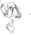
- the protective helmet 10 comprises an outer shell 12, which is preferably made of rigid material and dome shaped so as to fit over the user's head, and a visor 14, preferably made of rigid material, which is designed to be removably coupled to the outer shell 12.
- the visor 14 is preferably coupled to the outer shell 12 so as to project above a front opening 16 of the outer shell 12.
- FIG 1 a protective helmet 10, provided with a chin guard 18, is shown.
- teachings of the present invention can also be advantageously applied to the so-called "open-face helmets”.
- the visor 14 is removably coupled to the outer shell 12 by means of a fastening mechanism 20.
- the fastening mechanism 20 is positioned on facing surfaces of the outer shell 12 and the visor 14.
- the fastening mechanism 20 comprises complementarily shaped elements 22, 24 which comprise a protrusion 22 (see figures 7-9 ) and a receiving seat 24, which is provided with a flexible holding portion 26 (see figures 4-6 ).
- flexible holding portion there will be indicated a holding portion that is able to be deformed when a force is applied thereto and which will return to its original shape when the force is removed.
- the protrusion 22 is adapted to be removably fixed inside the receiving seat 24 by engaging the flexible holding portion 26.
- two protrusions 22 are positioned at the inner side ends of the visor 14 and two receiving seats 24 are positioned at corresponding locations of the outer shell 12.
- a third receiving seat 24 can be positioned along a midline of the outer shell 12 and a third protrusion 22 can be positioned at a corresponding location on the inner surface of the visor 14.
- the receiving seats 24 can be provided on the visor 14 and the protrusions 22 can be positioned on corresponding locations of the outer shell 12.
- each receiving seat 24 is preferably provided on a recessed area 28 of the outer shell 12.
- the receiving seat 24 can be inserted inside the recessed area 28 so as to be positioned flush with the outer shell 12.
- the receiving seat 24 is removably inserted inside the recessed area 28.
- each receiving seat 24 is provided with a flexible holding portion 26.
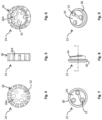
- the flexible holding portion 26 preferably comprises one or more flexible arms having hook shaped distal ends 26a, suitable for enclosing and hooking a perimetral portion 30 of the corresponding protrusion 22.
- the receiving seat 24 comprises a hollow body 32 and the flexible arms 26 are preferably provided at the perimetral portion of the hollow body 32.
- the hollow body 32 preferably has a circular shape.
- the flexible arms 26 substantially form a holding ring.
- the protrusion 22 is adapted to be inserted inside the hollow body 32 so that the flexible arms 26 engage the perimetral portion 30 of the protrusion 22 blocking the protrusion 22 inside the receiving seat 24.
- the holding action exerted by the flexible arms along the perimetral portion 30 of the protrusion 22 is suitable to keep the visor 14 firmly coupled to the outer shell 12 (see figure 14 ).
- the perimetral portion 30 of the protrusion 22 is suitable to space apart the flexible arms 26 so as to allow an easy disengagement of the protrusion 22 from the receiving seat 24 wherein it is fitted, and thus allowing the removal of the visor 14 from the outer shell 12.
- the protrusion 22 has a circular shape adapted to be inserted inside a receiving seat having a circular shape hollow body 32.
- the holding force exerted by the receiving seat 24 is substantially divided equally between the various flexible arms 26.
- the detaching of the visor 14 from the shell 12 will not be affected by the direction on which the detaching force acts.
- both the components of the detaching force namely the tangential component and the normal component, will be effective in releasing the visor from the shell.
- the detaching force acts along a specific direction, for example along a perpendicular direction to the shell.
- the protrusion 22 can comprise a rounded bulge 23, provided at a side surface of the protrusion 22.
- the bulge 23 is integral with the protrusion 22.
- the flexible holding portion 26 of the receiving seat 24 comprises a corresponding groove 27 designed to be engaged by the rounded bulge 23, when the protrusion 22 is fixed inside the receiving seat 24 (see figure 14A ).
- the protrusion 22 preferably made with a rigid material
- the flexible holding portion 26 of the receiving seat 24 comprises a corresponding groove 33 designed to be engaged by the blocking element 29, when the protrusion 22 is fixed inside the receiving seat 24 (see figure 14B ).
- the protrusion 22 and the holding portion 26 can have a circular shape. Consequently the bulge 23 and the blocking element 29 form a perimetral ring of the protrusion. Also in these embodiments, the detaching of the visor from the shell can be caused by a force acting along any direction.
- the flexible holding portion 26 can be provided with a bulge and a blocking element like those previously disclosed.
- the protrusion 22 will be provided with corresponding grooves.
- the receiving seat 24 is inserted inside the recessed area 28 leaving a perimetral gap.
- the flexible arms 26 can bent outwardly to allow the insertion and the removal of the protrusion 22 from the receiving seat 24.
- the hook shaped distal ends 26a of the flexible arms have rounded edges so as to make easier the coupling and decoupling of the protrusion 22 from the corresponding receiving seat 24.
- the perimetral portion 30 of the protrusion can be rounded.
- the perimetral portion 30 projects outwardly from a solid leg portion 34 of the protrusion 22.
- the perimetral portion 30, and as consequence the holding portion 26, has a circular shape.
- the protrusion can rotate inside the corresponding receiving seat around a transversal axis T (see figure 8 and 14 ).
- the latter thanks to the possible rotation of each protrusion 22 inside its receiving seat, can be adjusted with respect to the outer shell 12, even if it is firmly connected therein.
- the protrusion 22 can have an oval or triangular cross section.
- the inner surface of the visor abuts against an adjacent surface of the shell, allowing the visor to stay adherent to the shell.
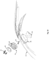
- the outer shell 12 can have a recessed area 36 shaped to complement a perimetric portion of the visor 14, so as to allow the visor 14 to be coupled flush with the outer shell 12.
- each receiving seat 24 is removably inserted inside the recessed area 28 provided in the outer shell 12, being sandwiched between two rigid fasteners 38, 40.
- a first fastener 38 is removably affixed inside the recessed area 28 by means of first screws 42 designed to engage corresponding seats provided in the first fastener 38.
- the bottom surface of the receiving seat 24 is designed to abut against the first fastener 38 and to be blocked therein by means of a second fastener 40 which, by means of second screws 44 engaging corresponding holes of the first fastener 38, is adapted to be connected to the first fastener 38.
- This particular arrangement allows an easy replacement of the receiving seat 24 if needed.
- each protrusion 22 is fastened to the inner surface of the visor 14 by means of a clip 46 having a shape complementarily fitting with a corresponding recess 48 provided on the outer surface of the visor 14.
- the clip 46 preferably is mounted flush with the outer surface of the visor 14 and is provided with protrusions 50 designed to be inserted inside through holes 52 of the recess 48.
- the protrusions 50 can advantageously engage corresponding seats 52 provided in the leg portion 34 of the protrusion 22 to which they are fastened by means of screws 54.
- the top surface of the protrusion is designed to abut against the second rigid fastener 40, so as to provide a firmer connection between visor and shell.
- the flexible holding portion 26 of the receiving seat 24 is made with elastic polymeric material, preferably thermoplastic polymeric material, like for example TPE (thermoplastic elastomer), TPEE (thermoplastic polyester elastomer) or TPU (thermoplastic polyurethane).
- thermoplastic polymeric material like for example TPE (thermoplastic elastomer), TPEE (thermoplastic polyester elastomer) or TPU (thermoplastic polyurethane).
- the elastic polymeric materials and in particular thermoplastic polymeric materials, combine a high elasticity with a high resistance and good resistance to impact.
- thermoplastic polymeric materials in particular of TPE, TPEE and TPU, assures a uniform behavior of the holding portion 26 across a wide range of temperature (from -30°C to +70°C).
- a holding portion 26 made with an elastic polymeric material has a hardness comprised between 58 and 68 shore D.
- the holding portion 26 made with an elastic polymeric material undergoes a temporary deformation of its shape when the protrusion is inserted therein. This deformation is self-reversing when the protrusion is extracted from the receiving seat 24 or inserted therein again.
- the protrusions 22 are made with rigid polymeric material like for example nylon or acetalic polymer.
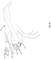
- a fastener pin 56 is positioned along a midline of the inner surface of the visor 14 and a receiving seat 58 is positioned at a corresponding location of the outer shell 12.
- the receiving seat 58 is advantageously provided with a central slot 60 designed to be engaged by the fastener pin 56.
- the central slot 60 is contoured so that the fastener pin 56 can engage the receiving seat 58 in different positions, for example in three different positions (see figures 16A-16C ).
- the visor 14 can be adjusted with respect to the outer shell 12, in particular with respect to a horizontal plane.
- the visor 14 can be positioned in a higher position (see figure 16A ).
- the visor 14 can be positioned in a lower position (see figure 16C ).
- the fastening mechanism 20 assures a firmly coupling between the visor 14 and the outer shell 12 during normal use, each protrusion 22 being steadily held by the holding portion of the corresponding receiving seat 24.
- the holding portion 26 being flexible allows an easy detachment of the protrusion 22 from the corresponding receiving seat so as to permit the detachment of the visor from the shell 12 in case of an impact or if it is needed.
- the detachment between the visor and the shell can take place in presence of an impact force coming from any direction.
- the release of the visor from the shell can happen not only when an impact force acts along a plane perpendicular to the surface of the shell, but also in case the impact force is inclined or parallel with respect to the shell.
- both the components of the impact force namely the tangential component and the normal component, will be effective in releasing the visor from the shell. In this way a higher protection against dangerous rotations of the helmet in case of impact is assured, without affecting the reliability of the connection between the visor and the helmet during normal use.
- the removably fixing of the receiving seat 24 inside the corresponding recessed area 28 allows an easy replacement of the receiving seat, if needed. As a matter of fact, such a replacement can be done by simply removing the screws connecting the first fastener to the second fastener.
- the inner surface of the visor can be positioned adherent to the outer surface of the shell, without creating any gap between the two components.
- the outer shell is provided with a recessed area shaped according to a perimetric portion of the visor, the latter can be advantageously mounted flush with the outer shell.
- the central slot 60 allows the visor to be easily adjusted with respect to the rider's eyes without affecting the coupling between the visor and the outer shell.
- this test concerns the measurement of the impact force needed for detaching the visor from the shell.
- the mechanisms differ in the dimensions: in the first one the circular protrusion has a diameter of 27mm and height of 4mm and the corresponding receiving seat has a diameter of 32mm and height of 10.5mm (hereinafter "big").
- the circular protrusion has a diameter of 17.7mm and height of 3.9mm and the corresponding receiving seat has a diameter of 22mm and height of 8.5mm (hereinafter "small").
- the receiving seats in both cases are made with TPEE (elastic polymeric material).
- the force requested to detach the fastening mechanisms has been measured, by simulating an impact force applied perpendicularly to the fastening mechanisms, but acting 27.5mm far from the longitudinal axis of the mechanisms.
- this test measures the capability of the visor of the helmet of the present invention to detach in case of impact from multiple directions.
- the first helmet is provided with a visor coupled to the shell according to the present invention, in particular by means of circular protrusions and corresponding receiving seats, the latter made with TPEE (hereinafter “detachable visor").
- a visor coupled to the shell according to the present invention, in particular by means of circular protrusions and corresponding receiving seats, the latter made with TPEE (hereinafter “detachable visor").
- the second helmet is provided with a visor and a shell like the first helmet, but having the visor blocked by means of screws to the shell (hereinafter "fixed visor").
- the impact has been simulated by means of a rod falling vertically with a speed of 2.5-2.75 m/s along a specific rig and impacting the visor near the tip.
- the PLA provides an indication about the force acting on the helmet during the impact; lower this value, lower the force on the helmet/head of the rider.
- the ⁇ v provides an indication about the energy absorbed by the helmet during the impact; lower this value, lower the energy transmitted to the head of the rider.
- a helmet according to the present invention provided with a visor able to be easily detached in case of an impact, is suitable to reduce the force and the energy transmitted to the head of the user during an accident.
- the visor has an effect during an impact since it increases the "leverage effect" of the helmet.
- Tests were carried out at an impact speed of 7.5m/s, on an oblique anvil.
- the helmet with the visor assembled (2nd and 3rd sample) was positioned so that the impact was about 5cm far from the tip of the visor; the helmet without visor (1st sample) was positioned so that the impact was in frontal area of the shell.
- the helmet according to the present invention has the additional advantage to reduce this "leverage effect", having lower values of PLA and PRA with respect to the third sample.
Landscapes
- Helmets And Other Head Coverings (AREA)
Claims (16)
- Casque de protection (10) comprenant:une coque externe (12);une visière (14) couplée, de manière amovible, à la coque externe (12) au moyen d'un mécanisme de fixation (20) positionné sur des surfaces en vis-à-vis de ladite coque externe (12) et de ladite visière (14);dans lequel le mécanisme de fixation (20) comprend des éléments de forme complémentaire (22, 24) comprenant au moins une saillie (22) et au moins un siège de réception (24) prévu avec une partie de support flexible (26); la au moins une saillie (22) étant adaptée pour être fixée, de manière amovible, à l'intérieur du au moins un siège de réception (24) en mettant en prise la partie de support flexible (26), caractérisé en ce que la partie de support flexible (26) est réalisée avec un matériau polymère élastique.
- Casque de protection (10) selon a revendication 1, caractérisé en ce qu'au moins deux saillies (22) sont positionnées au niveau des extrémités latérales internes de la visière (14) et au moins deux sièges de réception (24) sont positionnés aux emplacements correspondants de la coque externe (12).
- Casque de protection (10) selon la revendication 1, caractérisé en ce que le au moins un siège de réception (24) est prévu sur une zone enfoncée (28) de la coque externe (12) ; le au moins un siège de réception (24) étant à fleur avec la coque externe (12).
- Casque de protection (10) selon la revendication 1, caractérisé en ce que la partie de support flexible comprend un ou plusieurs bras flexibles (26) ayant des extrémités distales en forme de crochet (26a) adaptées pour fermer et accrocher une partie périmétrale (30) de la au moins une saillie (22).
- Casque de protection (10) selon la revendication 1, caractérisé en ce que le au moins un siège de réception (24) comprend un corps creux (32) adapté pour loger la au moins une saillie (22) lorsque la visière (14) et la coque externe (12) sont couplées entre elles.
- Casque de protection (10) selon la revendication 5, caractérisé en ce que les bras flexibles (26) sont prévus au niveau de la partie périmétrale du corps creux (32) du siège de réception (24).
- Casque de protection (10) selon la revendication 1, caractérisé en ce que la au moins une saillie (22) comprend un renflement arrondi (23), prévu sur une surface latérale de la au moins une saillie (22) ; la partie de support flexible (26) du au moins un siège de réception (24) comprenant une rainure (27) correspondante conçue pour être mise en prise par le renflement arrondi (23), lorsque la au moins une saillie (22) est fixée à l'intérieur du siège de réception (24).
- Casque de protection (10) selon la revendication 1, caractérisé en ce que la au moins une saillie (22) est prévue avec un élément de blocage (29), conçu pour être fixé dans une indentation (31) correspondante prévue sur la surface latérale de la au moins une saillie (22) ; la partie de support flexible (26) du siège de réception (24) comprenant une rainure (33) correspondante conçue pour être mise en prise par l'élément de blocage (29), lorsque la au moins une saillie (22) est fixée à l'intérieur du siège de réception (24).
- Casque de protection (10) selon la revendication 1, caractérisé en ce qu'une surface interne de la visière (14) est conçue pour venir en butée contre une surface adjacente de la coque externe (12), lorsque la au moins une saillie (22) met en prise le siège de réception (24) correspondant.
- Casque de protection (10) selon la revendication 4, caractérisé en ce que les extrémités distales en forme de crochet (26a) ont des bords arrondis.
- Casque de protection (10) selon la revendication 1, caractérisé en ce qu'au moins une broche de fixation (56) est positionnée le long d'une ligne médiane d'une surface interne de la visière (14) et en ce qu'au moins un siège de réception (58) est positionné à un emplacement correspondant de la coque externe (12).
- Casque de protection (10) selon la revendication 11, caractérisé en ce que le au moins un siège de réception (58) est prévu avec au moins une fente centrale (60) conçue pour être mise en prise par la au moins une broche de fixation (56).
- Casque de protection (10) selon la revendication 12, caractérisé en ce que la fente centrale (60) est profilée de sorte que la au moins une broche de fixation (56) est appropriée pour mettre en prise le au moins un siège de réception (58) dans différentes positions, afin de permettre à la visière (14) d'être ajustée par rapport à la coque externe (2).
- Casque de protection (10) selon la revendication 1, caractérisé en ce que la au moins une saillie (22) et la partie de support flexible (26) ont une forme circulaire.
- Casque de protection (10) selon les revendications 4 et 14, caractérisé en ce que les bras flexibles (26) forment une bague de support pour la partie périmétrale de la au moins une saillie (22).
- Casque de protection (10) selon la revendication 1, caractérisé en ce que le au moins un siège de réception (24) est inséré de manière amovible à l'intérieur d'une zone enfoncée (28) de la coque (12).
Applications Claiming Priority (2)
| Application Number | Priority Date | Filing Date | Title |
|---|---|---|---|
| IT102017000103682A IT201700103682A1 (it) | 2017-09-15 | 2017-09-15 | Casco protettivo |
| PCT/EP2018/074868 WO2019053183A1 (fr) | 2017-09-15 | 2018-09-14 | Casque de protection |
Publications (2)
| Publication Number | Publication Date |
|---|---|
| EP3681328A1 EP3681328A1 (fr) | 2020-07-22 |
| EP3681328B1 true EP3681328B1 (fr) | 2023-06-07 |
Family
ID=60813901
Family Applications (1)
| Application Number | Title | Priority Date | Filing Date |
|---|---|---|---|
| EP18766268.9A Active EP3681328B1 (fr) | 2017-09-15 | 2018-09-14 | Casque de protection |
Country Status (8)
| Country | Link |
|---|---|
| US (1) | US11540586B2 (fr) |
| EP (1) | EP3681328B1 (fr) |
| KR (1) | KR102604034B1 (fr) |
| CN (1) | CN111093414B (fr) |
| AU (1) | AU2018332264B2 (fr) |
| ES (1) | ES2949455T3 (fr) |
| IT (1) | IT201700103682A1 (fr) |
| WO (1) | WO2019053183A1 (fr) |
Families Citing this family (1)
| Publication number | Priority date | Publication date | Assignee | Title |
|---|---|---|---|---|
| WO2024047473A1 (fr) * | 2022-09-02 | 2024-03-07 | Alpinestars Research S.p.A. | Casque de protection doté de moyens de fixation pour au moins un appendice |
Family Cites Families (17)
| Publication number | Priority date | Publication date | Assignee | Title |
|---|---|---|---|---|
| DE1790999U (de) * | 1959-04-06 | 1959-06-25 | Pag Presswerk A G | Schutzhelm. |
| US3239842A (en) * | 1964-04-07 | 1966-03-15 | Joseph Buegeleisen Company | Safety helmet |
| DK159524C (da) * | 1986-06-25 | 1991-04-02 | Kemira Oy | Beskyttelseshjelm |
| US5522091A (en) * | 1994-03-21 | 1996-06-04 | Gentex Corporation | Sighter's protective helmet |
| JP3049207B2 (ja) * | 1996-06-07 | 2000-06-05 | 三菱マテリアル建材株式会社 | 型枠ブロック用安全手すり |
| JP3049207U (ja) * | 1997-11-26 | 1998-06-09 | 田辺ボーグ株式会社 | シールド付きヘルメット及びそのシールド |
| US6009561A (en) * | 1998-08-26 | 2000-01-04 | Bell Sports Inc. | Helmet with rotatable accessory mount and method of making the same |
| US6718559B1 (en) * | 2002-01-31 | 2004-04-13 | Howard Davidson | Motorcycle helmut snap-on decorative device |
| CN2827044Y (zh) * | 2005-10-25 | 2006-10-18 | 王明仁 | 一种防撞防滑安全头盔 |
| SE534868C2 (sv) * | 2010-05-07 | 2012-01-24 | Mips Ab | Hjälm med glidningsfrämjare anordnad vid ett energiabsorberande lager |
| US10070677B2 (en) * | 2010-10-05 | 2018-09-11 | Fox Head, Inc. | Attachment system for frontal helmet extension to a helmet |
| EP2759219B1 (fr) * | 2013-01-07 | 2016-09-21 | Strategic Sports Limited | Casque de bicyclette pourvu d'une visière |
| WO2015111231A1 (fr) * | 2014-01-22 | 2015-07-30 | ナックス株式会社 | Élément de retenue |
| US20150216247A1 (en) * | 2014-02-05 | 2015-08-06 | The Charlotte-Mecklenburg Hospital Authority D/B/A Carolinas Healthcare System | Impact reducing protective headgear |
| CN105077857B (zh) * | 2014-05-13 | 2018-08-28 | 菲玛股份公司 | 具有双级闭合的压力按扣 |
| SE539137C2 (en) * | 2015-05-15 | 2017-04-18 | Poc Sweden Ab | An attachment arrangement for a visor on a helmet |
| US20170367425A1 (en) * | 2016-06-27 | 2017-12-28 | Navstar Electronics Co., Ltd. | Structure for fixing riding recorder with helmet visor fastener |
-
2017
- 2017-09-15 IT IT102017000103682A patent/IT201700103682A1/it unknown
-
2018
- 2018-09-14 KR KR1020207006553A patent/KR102604034B1/ko active IP Right Grant
- 2018-09-14 EP EP18766268.9A patent/EP3681328B1/fr active Active
- 2018-09-14 CN CN201880059012.8A patent/CN111093414B/zh active Active
- 2018-09-14 AU AU2018332264A patent/AU2018332264B2/en active Active
- 2018-09-14 US US16/646,877 patent/US11540586B2/en active Active
- 2018-09-14 ES ES18766268T patent/ES2949455T3/es active Active
- 2018-09-14 WO PCT/EP2018/074868 patent/WO2019053183A1/fr unknown
Also Published As
| Publication number | Publication date |
|---|---|
| AU2018332264B2 (en) | 2023-12-07 |
| EP3681328A1 (fr) | 2020-07-22 |
| AU2018332264A1 (en) | 2020-03-05 |
| ES2949455T3 (es) | 2023-09-28 |
| KR20200052878A (ko) | 2020-05-15 |
| US20200275725A1 (en) | 2020-09-03 |
| CN111093414B (zh) | 2023-06-16 |
| WO2019053183A1 (fr) | 2019-03-21 |
| KR102604034B1 (ko) | 2023-11-20 |
| CN111093414A (zh) | 2020-05-01 |
| US11540586B2 (en) | 2023-01-03 |
| IT201700103682A1 (it) | 2019-03-15 |
Similar Documents
| Publication | Publication Date | Title |
|---|---|---|
| EP2061352B1 (fr) | Casque de protection | |
| US6202223B1 (en) | Padding with embedded fastener for use in a helmet | |
| US9572391B2 (en) | Protective helmet and insert with concussion reduction features | |
| US8209784B2 (en) | Helmet with an attachment mechanism for a faceguard | |
| US4631758A (en) | Protective headgear | |
| US20170215507A1 (en) | Protective Helmet for Lateral and Direct Impacts | |
| US20160270473A1 (en) | Mechanically-Fastened TPU Jaw Pad | |
| US20100192286A1 (en) | Buckle for a chin strap assembly for a sports helmet | |
| US20120279506A1 (en) | Mouthguard with impact gap | |
| US11882893B2 (en) | Impact attenuating helmet with inner and outer liner and securing attachment | |
| EP3681328B1 (fr) | Casque de protection | |
| EP3384794B1 (fr) | Structure de fixation de tampon détachable de casque et casque la comprenant | |
| CA2772644C (fr) | Casque protecteur et insert concu pour reduire les commotions | |
| CN110811052A (zh) | 具有前端安置系统弹性连接器的头盔 | |
| EP2759218B1 (fr) | Casque | |
| KR101001751B1 (ko) | 줄자를 갖는 안전모 | |
| KR200433393Y1 (ko) | 안전모 | |
| EP4201243A1 (fr) | Ensemble amortisseur, équipement de protection personnel le comprenant, élément déformable associé et procédé de montage par rattrapage d'un tel ensemble | |
| EP4369976A1 (fr) | Casque de protection |
Legal Events
| Date | Code | Title | Description |
|---|---|---|---|
| STAA | Information on the status of an ep patent application or granted ep patent |
Free format text: STATUS: UNKNOWN |
|
| STAA | Information on the status of an ep patent application or granted ep patent |
Free format text: STATUS: THE INTERNATIONAL PUBLICATION HAS BEEN MADE |
|
| PUAI | Public reference made under article 153(3) epc to a published international application that has entered the european phase |
Free format text: ORIGINAL CODE: 0009012 |
|
| STAA | Information on the status of an ep patent application or granted ep patent |
Free format text: STATUS: REQUEST FOR EXAMINATION WAS MADE |
|
| 17P | Request for examination filed |
Effective date: 20200309 |
|
| AK | Designated contracting states |
Kind code of ref document: A1 Designated state(s): AL AT BE BG CH CY CZ DE DK EE ES FI FR GB GR HR HU IE IS IT LI LT LU LV MC MK MT NL NO PL PT RO RS SE SI SK SM TR |
|
| AX | Request for extension of the european patent |
Extension state: BA ME |
|
| DAV | Request for validation of the european patent (deleted) | ||
| DAX | Request for extension of the european patent (deleted) | ||
| RAP3 | Party data changed (applicant data changed or rights of an application transferred) |
Owner name: ALPINESTARS RESEARCH S.P.A. |
|
| RIN1 | Information on inventor provided before grant (corrected) |
Inventor name: PARISSENTI, ROBERTO Inventor name: MAZZAROLO, GIOVANNI |
|
| GRAP | Despatch of communication of intention to grant a patent |
Free format text: ORIGINAL CODE: EPIDOSNIGR1 |
|
| STAA | Information on the status of an ep patent application or granted ep patent |
Free format text: STATUS: GRANT OF PATENT IS INTENDED |
|
| INTG | Intention to grant announced |
Effective date: 20220915 |
|
| GRAS | Grant fee paid |
Free format text: ORIGINAL CODE: EPIDOSNIGR3 |
|
| GRAA | (expected) grant |
Free format text: ORIGINAL CODE: 0009210 |
|
| STAA | Information on the status of an ep patent application or granted ep patent |
Free format text: STATUS: THE PATENT HAS BEEN GRANTED |
|
| AK | Designated contracting states |
Kind code of ref document: B1 Designated state(s): AL AT BE BG CH CY CZ DE DK EE ES FI FR GB GR HR HU IE IS IT LI LT LU LV MC MK MT NL NO PL PT RO RS SE SI SK SM TR |
|
| REG | Reference to a national code |
Ref country code: GB Ref legal event code: FG4D |
|
| REG | Reference to a national code |
Ref country code: CH Ref legal event code: EP Ref country code: AT Ref legal event code: REF Ref document number: 1572068 Country of ref document: AT Kind code of ref document: T Effective date: 20230615 |
|
| REG | Reference to a national code |
Ref country code: DE Ref legal event code: R096 Ref document number: 602018051167 Country of ref document: DE |
|
| P01 | Opt-out of the competence of the unified patent court (upc) registered |
Effective date: 20230608 |
|
| PGFP | Annual fee paid to national office [announced via postgrant information from national office to epo] |
Ref country code: FR Payment date: 20230613 Year of fee payment: 6 |
|
| REG | Reference to a national code |
Ref country code: NL Ref legal event code: FP |
|
| PGFP | Annual fee paid to national office [announced via postgrant information from national office to epo] |
Ref country code: NL Payment date: 20230725 Year of fee payment: 6 |
|
| REG | Reference to a national code |
Ref country code: LT Ref legal event code: MG9D |
|
| REG | Reference to a national code |
Ref country code: SE Ref legal event code: TRGR |
|
| REG | Reference to a national code |
Ref country code: ES Ref legal event code: FG2A Ref document number: 2949455 Country of ref document: ES Kind code of ref document: T3 Effective date: 20230928 |
|
| PG25 | Lapsed in a contracting state [announced via postgrant information from national office to epo] |
Ref country code: NO Free format text: LAPSE BECAUSE OF FAILURE TO SUBMIT A TRANSLATION OF THE DESCRIPTION OR TO PAY THE FEE WITHIN THE PRESCRIBED TIME-LIMIT Effective date: 20230907 |
|
| PGFP | Annual fee paid to national office [announced via postgrant information from national office to epo] |
Ref country code: IT Payment date: 20230904 Year of fee payment: 6 Ref country code: GB Payment date: 20230913 Year of fee payment: 6 |
|
| REG | Reference to a national code |
Ref country code: AT Ref legal event code: MK05 Ref document number: 1572068 Country of ref document: AT Kind code of ref document: T Effective date: 20230607 |
|
| PG25 | Lapsed in a contracting state [announced via postgrant information from national office to epo] |
Ref country code: RS Free format text: LAPSE BECAUSE OF FAILURE TO SUBMIT A TRANSLATION OF THE DESCRIPTION OR TO PAY THE FEE WITHIN THE PRESCRIBED TIME-LIMIT Effective date: 20230607 Ref country code: LV Free format text: LAPSE BECAUSE OF FAILURE TO SUBMIT A TRANSLATION OF THE DESCRIPTION OR TO PAY THE FEE WITHIN THE PRESCRIBED TIME-LIMIT Effective date: 20230607 Ref country code: LT Free format text: LAPSE BECAUSE OF FAILURE TO SUBMIT A TRANSLATION OF THE DESCRIPTION OR TO PAY THE FEE WITHIN THE PRESCRIBED TIME-LIMIT Effective date: 20230607 Ref country code: HR Free format text: LAPSE BECAUSE OF FAILURE TO SUBMIT A TRANSLATION OF THE DESCRIPTION OR TO PAY THE FEE WITHIN THE PRESCRIBED TIME-LIMIT Effective date: 20230607 Ref country code: GR Free format text: LAPSE BECAUSE OF FAILURE TO SUBMIT A TRANSLATION OF THE DESCRIPTION OR TO PAY THE FEE WITHIN THE PRESCRIBED TIME-LIMIT Effective date: 20230908 |
|
| PGFP | Annual fee paid to national office [announced via postgrant information from national office to epo] |
Ref country code: SE Payment date: 20230619 Year of fee payment: 6 |
|
| PG25 | Lapsed in a contracting state [announced via postgrant information from national office to epo] |
Ref country code: FI Free format text: LAPSE BECAUSE OF FAILURE TO SUBMIT A TRANSLATION OF THE DESCRIPTION OR TO PAY THE FEE WITHIN THE PRESCRIBED TIME-LIMIT Effective date: 20230607 |
|
| PG25 | Lapsed in a contracting state [announced via postgrant information from national office to epo] |
Ref country code: SK Free format text: LAPSE BECAUSE OF FAILURE TO SUBMIT A TRANSLATION OF THE DESCRIPTION OR TO PAY THE FEE WITHIN THE PRESCRIBED TIME-LIMIT Effective date: 20230607 |
|
| PGFP | Annual fee paid to national office [announced via postgrant information from national office to epo] |
Ref country code: ES Payment date: 20231003 Year of fee payment: 6 |
|
| PG25 | Lapsed in a contracting state [announced via postgrant information from national office to epo] |
Ref country code: IS Free format text: LAPSE BECAUSE OF FAILURE TO SUBMIT A TRANSLATION OF THE DESCRIPTION OR TO PAY THE FEE WITHIN THE PRESCRIBED TIME-LIMIT Effective date: 20231007 |
|
| PG25 | Lapsed in a contracting state [announced via postgrant information from national office to epo] |
Ref country code: SM Free format text: LAPSE BECAUSE OF FAILURE TO SUBMIT A TRANSLATION OF THE DESCRIPTION OR TO PAY THE FEE WITHIN THE PRESCRIBED TIME-LIMIT Effective date: 20230607 Ref country code: SK Free format text: LAPSE BECAUSE OF FAILURE TO SUBMIT A TRANSLATION OF THE DESCRIPTION OR TO PAY THE FEE WITHIN THE PRESCRIBED TIME-LIMIT Effective date: 20230607 Ref country code: RO Free format text: LAPSE BECAUSE OF FAILURE TO SUBMIT A TRANSLATION OF THE DESCRIPTION OR TO PAY THE FEE WITHIN THE PRESCRIBED TIME-LIMIT Effective date: 20230607 Ref country code: PT Free format text: LAPSE BECAUSE OF FAILURE TO SUBMIT A TRANSLATION OF THE DESCRIPTION OR TO PAY THE FEE WITHIN THE PRESCRIBED TIME-LIMIT Effective date: 20231009 Ref country code: IS Free format text: LAPSE BECAUSE OF FAILURE TO SUBMIT A TRANSLATION OF THE DESCRIPTION OR TO PAY THE FEE WITHIN THE PRESCRIBED TIME-LIMIT Effective date: 20231007 Ref country code: EE Free format text: LAPSE BECAUSE OF FAILURE TO SUBMIT A TRANSLATION OF THE DESCRIPTION OR TO PAY THE FEE WITHIN THE PRESCRIBED TIME-LIMIT Effective date: 20230607 Ref country code: CZ Free format text: LAPSE BECAUSE OF FAILURE TO SUBMIT A TRANSLATION OF THE DESCRIPTION OR TO PAY THE FEE WITHIN THE PRESCRIBED TIME-LIMIT Effective date: 20230607 Ref country code: AT Free format text: LAPSE BECAUSE OF FAILURE TO SUBMIT A TRANSLATION OF THE DESCRIPTION OR TO PAY THE FEE WITHIN THE PRESCRIBED TIME-LIMIT Effective date: 20230607 |
|
| PGFP | Annual fee paid to national office [announced via postgrant information from national office to epo] |
Ref country code: DE Payment date: 20230927 Year of fee payment: 6 |
|
| PG25 | Lapsed in a contracting state [announced via postgrant information from national office to epo] |
Ref country code: PL Free format text: LAPSE BECAUSE OF FAILURE TO SUBMIT A TRANSLATION OF THE DESCRIPTION OR TO PAY THE FEE WITHIN THE PRESCRIBED TIME-LIMIT Effective date: 20230607 |
|
| REG | Reference to a national code |
Ref country code: DE Ref legal event code: R097 Ref document number: 602018051167 Country of ref document: DE |
|
| PLBE | No opposition filed within time limit |
Free format text: ORIGINAL CODE: 0009261 |
|
| STAA | Information on the status of an ep patent application or granted ep patent |
Free format text: STATUS: NO OPPOSITION FILED WITHIN TIME LIMIT |
|
| PG25 | Lapsed in a contracting state [announced via postgrant information from national office to epo] |
Ref country code: DK Free format text: LAPSE BECAUSE OF FAILURE TO SUBMIT A TRANSLATION OF THE DESCRIPTION OR TO PAY THE FEE WITHIN THE PRESCRIBED TIME-LIMIT Effective date: 20230607 |
|
| REG | Reference to a national code |
Ref country code: CH Ref legal event code: PL |
|
| PG25 | Lapsed in a contracting state [announced via postgrant information from national office to epo] |
Ref country code: SI Free format text: LAPSE BECAUSE OF FAILURE TO SUBMIT A TRANSLATION OF THE DESCRIPTION OR TO PAY THE FEE WITHIN THE PRESCRIBED TIME-LIMIT Effective date: 20230607 |
|
| 26N | No opposition filed |
Effective date: 20240308 |
|
| PG25 | Lapsed in a contracting state [announced via postgrant information from national office to epo] |
Ref country code: LU Free format text: LAPSE BECAUSE OF NON-PAYMENT OF DUE FEES Effective date: 20230914 |