EP3681084B1 - Short physical downlink control channel (spdcch) mapping design - Google Patents
Short physical downlink control channel (spdcch) mapping design Download PDFInfo
- Publication number
- EP3681084B1 EP3681084B1 EP19206593.6A EP19206593A EP3681084B1 EP 3681084 B1 EP3681084 B1 EP 3681084B1 EP 19206593 A EP19206593 A EP 19206593A EP 3681084 B1 EP3681084 B1 EP 3681084B1
- Authority
- EP
- European Patent Office
- Prior art keywords
- spdcch
- pdcch
- prb
- sreg
- frequency
- Prior art date
- Legal status (The legal status is an assumption and is not a legal conclusion. Google has not performed a legal analysis and makes no representation as to the accuracy of the status listed.)
- Active
Links
- 238000013507 mapping Methods 0.000 title claims description 64
- 238000013461 design Methods 0.000 title description 19
- 101150071746 Pbsn gene Proteins 0.000 claims description 72
- 230000005540 biological transmission Effects 0.000 claims description 54
- 238000000034 method Methods 0.000 claims description 42
- 238000012545 processing Methods 0.000 description 33
- 230000002776 aggregation Effects 0.000 description 28
- 238000004220 aggregation Methods 0.000 description 28
- 238000010586 diagram Methods 0.000 description 15
- 238000004891 communication Methods 0.000 description 13
- 230000011664 signaling Effects 0.000 description 12
- 230000006870 function Effects 0.000 description 10
- 230000008569 process Effects 0.000 description 10
- 238000013468 resource allocation Methods 0.000 description 9
- 125000004122 cyclic group Chemical group 0.000 description 6
- 238000005516 engineering process Methods 0.000 description 6
- 101100288133 Mus musculus Klk7 gene Proteins 0.000 description 4
- 230000008901 benefit Effects 0.000 description 3
- 239000013256 coordination polymer Substances 0.000 description 3
- 230000001419 dependent effect Effects 0.000 description 3
- 235000021190 leftovers Nutrition 0.000 description 3
- 230000007774 longterm Effects 0.000 description 3
- 230000009467 reduction Effects 0.000 description 3
- 208000037918 transfusion-transmitted disease Diseases 0.000 description 3
- 230000006978 adaptation Effects 0.000 description 2
- 230000003287 optical effect Effects 0.000 description 2
- 230000015572 biosynthetic process Effects 0.000 description 1
- 230000000903 blocking effect Effects 0.000 description 1
- 239000000969 carrier Substances 0.000 description 1
- 230000001413 cellular effect Effects 0.000 description 1
- 230000002349 favourable effect Effects 0.000 description 1
- 238000005259 measurement Methods 0.000 description 1
- 238000010295 mobile communication Methods 0.000 description 1
- 238000012544 monitoring process Methods 0.000 description 1
- 230000010363 phase shift Effects 0.000 description 1
- 230000004043 responsiveness Effects 0.000 description 1
- 238000004904 shortening Methods 0.000 description 1
- 238000012360 testing method Methods 0.000 description 1
- 230000036962 time dependent Effects 0.000 description 1
- 238000012546 transfer Methods 0.000 description 1
Images


Classifications
-
- H—ELECTRICITY
- H04—ELECTRIC COMMUNICATION TECHNIQUE
- H04L—TRANSMISSION OF DIGITAL INFORMATION, e.g. TELEGRAPHIC COMMUNICATION
- H04L5/00—Arrangements affording multiple use of the transmission path
- H04L5/0001—Arrangements for dividing the transmission path
- H04L5/0003—Two-dimensional division
- H04L5/0005—Time-frequency
- H04L5/0007—Time-frequency the frequencies being orthogonal, e.g. OFDM(A), DMT
-
- H—ELECTRICITY
- H04—ELECTRIC COMMUNICATION TECHNIQUE
- H04L—TRANSMISSION OF DIGITAL INFORMATION, e.g. TELEGRAPHIC COMMUNICATION
- H04L5/00—Arrangements affording multiple use of the transmission path
- H04L5/003—Arrangements for allocating sub-channels of the transmission path
- H04L5/0048—Allocation of pilot signals, i.e. of signals known to the receiver
- H04L5/005—Allocation of pilot signals, i.e. of signals known to the receiver of common pilots, i.e. pilots destined for multiple users or terminals
-
- H—ELECTRICITY
- H04—ELECTRIC COMMUNICATION TECHNIQUE
- H04L—TRANSMISSION OF DIGITAL INFORMATION, e.g. TELEGRAPHIC COMMUNICATION
- H04L27/00—Modulated-carrier systems
- H04L27/26—Systems using multi-frequency codes
- H04L27/2601—Multicarrier modulation systems
- H04L27/2602—Signal structure
- H04L27/2605—Symbol extensions, e.g. Zero Tail, Unique Word [UW]
- H04L27/2607—Cyclic extensions
-
- H—ELECTRICITY
- H04—ELECTRIC COMMUNICATION TECHNIQUE
- H04L—TRANSMISSION OF DIGITAL INFORMATION, e.g. TELEGRAPHIC COMMUNICATION
- H04L5/00—Arrangements affording multiple use of the transmission path
- H04L5/003—Arrangements for allocating sub-channels of the transmission path
- H04L5/0048—Allocation of pilot signals, i.e. of signals known to the receiver
- H04L5/0051—Allocation of pilot signals, i.e. of signals known to the receiver of dedicated pilots, i.e. pilots destined for a single user or terminal
-
- H—ELECTRICITY
- H04—ELECTRIC COMMUNICATION TECHNIQUE
- H04L—TRANSMISSION OF DIGITAL INFORMATION, e.g. TELEGRAPHIC COMMUNICATION
- H04L5/00—Arrangements affording multiple use of the transmission path
- H04L5/003—Arrangements for allocating sub-channels of the transmission path
- H04L5/0053—Allocation of signaling, i.e. of overhead other than pilot signals
-
- H—ELECTRICITY
- H04—ELECTRIC COMMUNICATION TECHNIQUE
- H04L—TRANSMISSION OF DIGITAL INFORMATION, e.g. TELEGRAPHIC COMMUNICATION
- H04L5/00—Arrangements affording multiple use of the transmission path
- H04L5/003—Arrangements for allocating sub-channels of the transmission path
- H04L5/0058—Allocation criteria
- H04L5/0064—Rate requirement of the data, e.g. scalable bandwidth, data priority
-
- H—ELECTRICITY
- H04—ELECTRIC COMMUNICATION TECHNIQUE
- H04L—TRANSMISSION OF DIGITAL INFORMATION, e.g. TELEGRAPHIC COMMUNICATION
- H04L5/00—Arrangements affording multiple use of the transmission path
- H04L5/003—Arrangements for allocating sub-channels of the transmission path
- H04L5/0058—Allocation criteria
- H04L5/0076—Allocation utility-based
-
- H—ELECTRICITY
- H04—ELECTRIC COMMUNICATION TECHNIQUE
- H04L—TRANSMISSION OF DIGITAL INFORMATION, e.g. TELEGRAPHIC COMMUNICATION
- H04L5/00—Arrangements affording multiple use of the transmission path
- H04L5/003—Arrangements for allocating sub-channels of the transmission path
- H04L5/0078—Timing of allocation
- H04L5/0082—Timing of allocation at predetermined intervals
-
- H—ELECTRICITY
- H04—ELECTRIC COMMUNICATION TECHNIQUE
- H04W—WIRELESS COMMUNICATION NETWORKS
- H04W24/00—Supervisory, monitoring or testing arrangements
- H04W24/08—Testing, supervising or monitoring using real traffic
-
- H—ELECTRICITY
- H04—ELECTRIC COMMUNICATION TECHNIQUE
- H04W—WIRELESS COMMUNICATION NETWORKS
- H04W72/00—Local resource management
- H04W72/04—Wireless resource allocation
- H04W72/044—Wireless resource allocation based on the type of the allocated resource
- H04W72/0446—Resources in time domain, e.g. slots or frames
-
- H—ELECTRICITY
- H04—ELECTRIC COMMUNICATION TECHNIQUE
- H04W—WIRELESS COMMUNICATION NETWORKS
- H04W72/00—Local resource management
- H04W72/04—Wireless resource allocation
- H04W72/044—Wireless resource allocation based on the type of the allocated resource
- H04W72/0453—Resources in frequency domain, e.g. a carrier in FDMA
-
- H—ELECTRICITY
- H04—ELECTRIC COMMUNICATION TECHNIQUE
- H04W—WIRELESS COMMUNICATION NETWORKS
- H04W76/00—Connection management
- H04W76/20—Manipulation of established connections
- H04W76/27—Transitions between radio resource control [RRC] states
-
- H—ELECTRICITY
- H04—ELECTRIC COMMUNICATION TECHNIQUE
- H04L—TRANSMISSION OF DIGITAL INFORMATION, e.g. TELEGRAPHIC COMMUNICATION
- H04L5/00—Arrangements affording multiple use of the transmission path
- H04L5/0091—Signaling for the administration of the divided path
- H04L5/0094—Indication of how sub-channels of the path are allocated
Definitions
- Wireless communications and in particular, short physical downlink control channel (sPDCCH) mapping design.
- sPDCCH short physical downlink control channel
- ERICSSON "Design aspects of sPDCCH", 3GPP DRAFT; R1-1610323, 3RD GENERATION PARTNERSHIP PROJECT (3GPP), RAN WG1, no. Lisbon, Portugal , describes options for support for both CRS and DMRS based transmission of sPDCCH, based on a different design or a common design.
- LTE long term evolution
- E-UTRAN evolved universal terrestrial radio access network
- UE user-equipment
- NR 5G New Radio
- Packet data latency is one of the performance metrics that vendors, operators and also end-users (via speed test applications) regularly measure. Latency measurements are done in all phases of a radio access network system lifetime, when verifying a new software release or system component, when deploying a system and when the system is in commercial operation.
- LTE Long Term Evolution
- HTTP/TCP hypertext transfer protocol/ transmission control protocol
- Kbytes kilobytes
- Mbyte 1 megabyte
- TCP slow start period is a significant part of the total transport period of the packet stream.
- TCP slow start the performance is latency limited. Hence, improved latency can rather easily be shown to improve the average throughput, for this type of TCP based data transactions.
- Radio resource efficiency could be positively impacted by latency reductions.
- Lower packet data latency could increase the number of transmissions possible within a certain delay bound; hence higher Block Error Rate (BLER) targets could be used for the data transmissions freeing up radio resources potentially improving the capacity of the system.
- BLER Block Error Rate
- TTI transmission time interval
- SF subframe
- SC-FDMA single carrier frequency division multiple access
- sTTI short physical downlink shared channel
- sPUSCH short physical uplink shared channel
- sPUSCH short physical uplink shared channel
- sTTI schedule a sTTI in the UL or DL to a wireless device.
- individual wireless devices receive information about sPDCCH candidates for short TTI via radio resource control (RRC) configuration, telling the wireless device where to look for the control channel for short TTI, i.e., sPDCCH.
- RRC radio resource control
- the downlink control information (DCI) for sTTI is actually included directly in sPDCCH.
- the DCI for sTTI is split into two parts, a slow DCI sent in the PDCCH and a fast DCI sent in the sPDCCH.
- the slow grant can contain the frequency allocation for a DL and an UL short TTI band to be used for short TTI operation, and it can also contain refinement about the sPDCCH candidate locations.
- 3GPP Long Term Evolution (LTE) technology is a mobile broadband wireless communication technology in which transmissions from base stations (referred to as eNBs) to mobile stations (referred to as wireless devices (WDs)) are sent using orthogonal frequency division multiplexing (OFDM).
- OFDM orthogonal frequency division multiplexing
- the basic unit of transmission in LTE is a resource block (RB) which in its most common configuration consists of 12 subcarriers and 7 OFDM symbols (one slot) in the case of normal cyclic prefix.
- a RB consists of 6 OFDM symbols in the time domain.
- a common term is also a physical resource block (PRB) to indicate the RB in the physical resource. Two PRBs in the same subframe that use the same 12 subcarriers are denoted a PRB pair. This is the minimum resource unit that can be scheduled in LTE.
- PRB physical resource block
- a unit of one subcarrier and 1 OFDM symbol is referred to as a resource element (RE, as shown in FIG. 1 .
- a PRB consists of 84 REs.
- An LTE radio subframe is composed of multiple resource blocks in frequency with the number of PRBs determining the bandwidth of the system and two slots in time as shown in FIG. 2
- Messages transmitted over the radio link to users can be broadly classified as control messages or data messages.
- Control messages are used to facilitate the proper operation of the system as well as proper operation of each wireless device within the system.
- Control messages could include commands to control functions such as the transmitted power from a wireless device, signaling of RBs within which the data is to be received by the wireless device or transmitted from the wireless device and so on.
- Rel-8 the first one to four OFDM symbols, depending on the configuration, in a subframe are reserved to contain such control information, as shown in FIG. 2 .
- an enhanced control channel was introduced (evolved physical downlink control channel -EPDCCH)), in which PRB pairs are reserved to exclusively contain EPDCCH transmissions, while excluding from the PRB pair the one to four first symbols that may contain control information to wireless devices of releases earlier than Rel-11. See FIG. 3 .
- the EPDCCH is frequency multiplexed with PDSCH transmissions, contrary to the PDCCH which is time multiplexed with the PDSCH transmissions.
- the resource allocation (RA) for PDSCH transmissions exists in several RA types, depending on the downlink control information (DCI) format. Some RA types has a minimum scheduling granularity of a resource block group (RBG), see TS 36.211.
- An RBG is a set of adjacent (in frequency) resource blocks and when scheduling the wireless device, the wireless device is allocated resources in terms of RBGs and not individual RBs.
- the wireless device When a wireless device is scheduled in the downlink from an EPDCCH, the wireless device shall assume that the PRB pairs carrying the DL assignment are excluded from the resource allocation, i.e., rate matching applies. For example, if a wireless device is scheduled in the PDSCH in a certain RBG of size 3 adjacent PRB pairs, and one of these PRB pairs contain the DL assignment, the wireless device shall assume that the PDSCH is only transmitted in the two remaining PRB pairs in this RBG. Note also that multiplexing of PDSCH and any EPDCCH transmission within a PRB pair is not supported in Rel-11.
- the PDCCHs and EPDCCHs are transmitted over radio resources that are shared between several wireless devices (WDs).
- Each PDCCH consists of smaller parts, known as control channel elements (CCE), to enable link adaptation (by controlling the number of CCEs a PDCCH is utilizing).
- CCE control channel elements
- a wireless device must monitor 4 aggregation levels of CCEs, namely, 1, 2, 4, and 8, for a wireless device-specific search space and 2 aggregation levels of CCEs, namely, 4 and 8, for a common search space.
- Each CCE contains 36 quadrature phase shift keying (QPSK) modulation symbols.
- M ( L ) is specified by Table 9.1.1-1 in 36.213, as shown below: Table 1 Search space S k L Number of PDCCH candidates M ( L ) Type Aggregation level L Size [in CCEs] UE-specific 1 6 6 2 12 6 4 8 2 8 16 2 Common 4 16 4 8 16 2
- CCE control channel elements
- RE resource elements
- One PDCCH can, depending on the information payload size and the required level of channel coding protection, consist of 1, 2, 4 or 8 CCEs, and the number is denoted as the CCE aggregation level (AL). By choosing the aggregation level, link-adaptation of the PDCCH is obtained. In total there are N CCE CCEs available for all the PDCCHs to be transmitted in the subframe and the number N CCE varies from subframe to subframe depending on the number of control symbols n and the number of antenna ports configured.
- the terminal needs to blindly determine the position and the number of CCEs used for its PDCCH which can be a computationally intensive decoding task. Therefore, some restrictions on the number of possible blind decodings a terminal needs to go through have been introduced. For instance, the CCEs are numbered and CCE aggregation levels of size K can only start on CCE numbers evenly divisible by K , as shown in FIG. 4 .
- the set of candidate control channels formed by CCEs where a terminal needs to blindly decode and search for a valid PDCCH are called search spaces.
- a terminal In each subframe and on each AL, a terminal will attempt to decode all the PDCCHs that can be formed from the CCEs in its search space. If the CRC checks, then the content of the PDCCH is assumed to be valid for the terminal and it further processes the received information. Often, two or more terminals will have overlapping search spaces and the network has to select one of them for scheduling of the control channel. When this happens, the non-scheduled terminal is said to be blocked.
- the search spaces vary pseudo-randomly from subframe to subframe to minimize this blocking probability.
- a search space is further divided to a common and a terminal specific part.
- the PDCCH containing information to all or a group of terminals is transmitted (paging, system information, etc.). If carrier aggregation is used, a terminal will find the common search space present on the primary component carrier (PCC) only.
- the common search space is restricted to aggregation levels 4 and 8 to give sufficient channel code protection for all terminals in the cell (since it is a broadcast channel, link adaptation cannot be used).
- FIG. 5 shows the search space (highlighted) a certain terminal needs to monitor.
- N CCE 15 CCEs in this example and the common search space is marked with stripes.
- a CCE consists of 36 QPSK modulated symbols that map to the 36 RE unique for this CCE.
- interleaving of all the CCEs is used before a cell specific cyclic shift and mapping to REs are performed, as shown in FIG. 6 , blocks S10-S20.
- the empty CCEs are included in the interleaving process and mapping to RE as any other PDCCH to maintain the search space structure. Empty CCE are set to zero power and this power can instead be used by non-empty CCEs to further enhance the PDCCH transmission.
- a group of 4 adjacent QPSK symbols in a CCE is mapped to 4 adjacent RE, denoted a RE group (REG).
- REG RE group
- the EPDCCH is transmitted over radio resources shared by multiple wireless devices and enhanced CCEs (eCCEs) are introduced as the equivalent to CCE for PDCCH.
- eCCEs enhanced CCEs
- An eCCE has also a fixed number of REs but the number of REs available for EPDCCH mapping is generally fewer than this fixed number because many REs are occupied by other signals such as cell-specific reference signal (CRS), corresponding to CRS referred to as channel reference symbols, and channel state information reference signal (CSI-RS).
- CRS cell-specific reference signal
- CSI-RS channel state information reference signal
- Code chain rate matching is applied whenever a RE belonging to a eCCE contains other colliding signals such as the CRS, CSI-RS, legacy control region or in case of time division duplex (TDD), the guard period (GP) and uplink pilot time slots (UpPTS) 36.211.
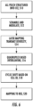
- (a) illustrates the PDCCH mapping, which avoids the CRS so that a CCE consists of available REs.
- (b) it is shown how the eCCE consists of 36 RE nominally, but the number of available REs is less in cases where there are colliding signals, hence RE for EPDCCH. Since the colliding signals are subframe dependent, the number REs that are available for eCCE becomes subframe dependent as well, and could even be different for different eCCEs if the collisions impact on the eCCEs unevenly.
- the PDCCH there is always 36 RE available (a), but here in (b), the nominal 36 are punctured so a lower value is available.
- the nominal number of RE per eCCE is not 36, but instead, 72 or 64 for normal and extended CP length respectively.
- the EPDCCH supports only the wireless device specific search space whereas the common search space remains to be monitored in the PDCCH in the same subframe.
- the common search space may be introduced also for EPDCCH transmission.
- the wireless device monitors eCCE aggregation levels 1, 2, 4, 8, 16 and 32 with restrictions shown.
- FIG. 8 shows a downlink subframe having 4 parts belonging to an EPDCCH that is mapped to multiples of the enhanced control regions known as PRB pairs, to achieve distributed transmission and frequency diversity or subband precoding.
- an EPDCCH is mapped to one PRB pair only, if the space allows (which is always possible for aggregation level one and two and for normal subframes and normal CP length also for level four).
- a second PRB pair is used as well, and so on, using more PRB pairs, until all eCCE belonging to the EPDCCH has been mapped. See FIG. 9 for an illustration of localized transmission.
- FIG. 9 shows a downlink subframe showing the 4 eCCEs belonging to an EPDCCH that is mapped to one of the enhanced control regions, to achieve localized transmission.
- each PRB pair is divided into 16 enhanced resource element groups (eREGs) and each eCCE is split into 4 or 8 eREGs for normal and extended cyclic prefix, respectively.
- An EPDCCH is consequently mapped to a multiple of four or eight eREGs depending on the aggregation level.
- eREGs belonging to an ePDCCH reside in either a single PRB pair (as is typical for localized transmission) or a multiple of PRB pairs (as is typical for distributed transmission).
- a new short PDCCH (sPDCCH) can be defined. Since the short TTI operation is desired to co-exist with legacy TTI operation, the sPDCCH should be placed in-band within the PDSCH, still leaving resources for legacy data.
- Legacy control channels PDCCH and EPDCCH use CRS and DMRS demodulation, respectively.
- an sPDCCH should support both CRS and DMRS, and to maintain efficiency, resources not used by sPDCCH should be used by the sPDSCH (the short PDSCH).
- sPDCCH A specific DL control channel for short TTI, called sPDCCH (PDCCH for short TTI) in this document, is introduced for short TTI.
- sPDCCH specific DL control channel for short TTI
- an efficient design is defined for mapping sPDCCH candidates to the resource elements (REs) of the time-frequency grid.
- Some embodiments advantageously provide a method, network node and wireless device for mapping a short physical downlink control channel, sPDCCH, to resource elements of a time-frequency grid to achieve one of high frequency diversity and condensed frequency allocation.
- a method in network node for mapping a short physical downlink control channel (sPDCCH) to resource elements of a time-frequency grid includes determining available time-frequency resources to be configured as short resource element groups (sREGs).
- the method also includes configuring sREGs within a physical resource block (PRB) to map the sPDCCH to the resource elements, each sREG spanning one OFDM symbol.
- PRB physical resource block
- an sREG consists of 1 PRB within 1 OFDM symbol including resource elements, REs, for at least one of cell-specific reference signal (CRS) and demodulation reference signals (DMRS) applied to DMRS-based sPDCCH.
- an sREG consists of 1 PRB within 1 OFDM symbol including resource elements, REs, for at least one of CRS and DMRS applied to CRS-based sPDCCH.
- the sREGs are configured to be one of localized in a frequency domain and distributed in the frequency domain.
- the method further includes configuring a wireless device by radio resource control (RRC) signaling to use a CRS based sPDCCH resource block set with one of distributed or localized mapping of short control channel elements (sCCE) to sREGs.
- RRC radio resource control
- the method further includes configuring a wireless device by RRC signaling to use a DMRS based sPDCCH resource block set with one of distributed or localized mapping of sCCE to sREGs.
- the method further includes configuring an sPDCCH PRB set with at least a set of PRBs and one of localized and distributed sCCE to sREG mapping.
- 1 OFDM symbol sPDCCH is defined for CRS based transmissions.
- a number of OFDM symbols per RB set is one of 1 and 2.
- a number of OFDM symbols per RB set is one of 1 and 2.
- a 2 OFDM symbol sPDCCH is defined for DMRS-based transmissions.
- a number of OFDM symbols per RB set is 2.
- a number of OFDM symbols per RB set is 3. In some embodiments, for DMRS based sPDCCH, with 1 slot sTTI a number of OFDM symbols per RB set is 2.
- a network node for mapping a short physical downlink control channel, sPDCCH, to resource elements of a time-frequency grid.
- the network node includes processing circuitry configured to determine available time-frequency resources to be configured as short resource element groups (sREGs).
- the processing circuitry is further configured to configure sREGs within a physical resource block (PRB) to map the sPDCCH to the resource elements, each sREG spanning one OFDM symbol.
- PRB physical resource block
- an sREG consists of 1 PRB within 1 OFDM symbol including resource elements (REs) for at least one of CRS and DMRS applied to DMRS-based sPDCCH. In some embodiments, an sREG consists of 1 PRB within 1 OFDM symbol including REs for at least one of CRS and DMRS applied to CRS-based sPDCCH. In some embodiments, the sREGs are configured to be one of localized in a frequency domain and distributed in the frequency domain. In some embodiments, the processing circuitry is further configured to configure a wireless device by RRC to use a CRS based sPDCCH resource block set with one of distributed or localized mapping of sCCE to sREGs.
- RRC resource elements
- the processing circuitry is further configured to configure a wireless device by RRC signaling to use a DMRS based sPDCCH resource block set with one of distributed or localized mapping of sCCE, to sREGs.
- the processing circuitry is further configured to configure an sPDCCH PRB set with at least a set of PRBs, and one of localized and distributed sCCE to sREG mapping.
- 1 OFDM symbol sPDCCH is defined for cell-specific reference signal (CRS) based transmissions.
- CRS cell-specific reference signal
- a number of OFDM symbols per RB set is one of 1 and 2.
- a number of OFDM symbols per RB set is one of 1 and 2.
- a 2 OFDM symbol sPDCCH is defined for DMRS-based transmissions.
- for DMRS based sPDCCH with 2 sPDCCH symbol sTTI a number of OFDM symbols per RB set is 2.
- DMRS based sPDCCH with 3 symbol sTTI a number of OFDM symbols per RB set is 3.
- for DMRS based sPDCCH with 1 slot sTTI a number of OFDM symbols per RB set is 2.
- a network node for mapping a short physical downlink control channel (sPDCCH) to resource elements of a time-frequency grid to achieve one of high frequency diversity and condensed frequency allocation.
- the network node includes a memory module configured to store a mapping of the sPDCCH to resource elements of a time-frequency grid.
- the network further includes a short resource element group (sREG) configuration module configured to configure sREGs within a physical resource block (PRB), to map the sPDCCH to the resource elements, each sREG spanning one OFDM symbol.
- sREG short resource element group
- a method in a wireless device for receiving information on a sPDCCH signaled by a network node, the sPDCCH being mapped to resource elements of a time-frequency grid, by configuring sREGs includes receiving the sPDCCH from the network node on one of a plurality of sets of PRBs.
- the sPDCCH is of 2 OFDM symbols.
- the method further includes receiving an indication of a sequential order of PRBs from the network node.
- a wireless device for receiving information on a sPDCCH signaled by a network node, the sPDCCH being mapped to resource elements of a time-frequency grid, by configuring sREGs, each sREG spanning one orthogonal frequency division multiplex, OFDM, symbol is provided.
- the wireless device includes a transceiver configured to receive the sPDCCH from the network node on one of a plurality of sets of PRBs.
- the sPDCCH is of 2 OFDM symbols.
- the transceiver is further configured to receive an indication of a sequential order of PRBs from the network node.
- a wireless device for receiving information on a sPDCCH signaled by a network node, the sPDCCH being mapped to resource elements of a time-frequency grid, by configuring sREGs.
- the wireless device includes a transceiver module configured to receive the sPDCCH from the network node on one of a plurality of sets of PRBs.
- relational terms such as “first” and “second,” “top” and “bottom,” and the like, may be used solely to distinguish one entity or element from another entity or element without necessarily requiring or implying any physical or logical relationship or order between such entities or elements.
- functions described herein as being performed by a wireless device or a network node may be distributed over a plurality of wireless devices and/or network nodes.
- the functions of the network node and wireless device described herein are not limited to performance by a single physical device and, in fact, can be distributed among several physical devices.
- wireless device or user equipment may refer to any type of wireless device communicating with a network node and/or with another wireless device in a cellular or mobile communication system.
- Examples of a wireless device are target device, device to device (D2D) wireless device, machine type wireless device or wireless device capable of machine to machine (M2M) communication, PDA, iPAD, Tablet, mobile terminals, smart phone, laptop embedded equipped (LEE), laptop mounted equipment (LME), USB dongles etc.
- network node used herein may refer to a radio network node or another network node, e.g., a core network node, MSC, MME, O&M, OSS, SON, positioning node (e.g. E-SMLC), MDT node, etc.
- a radio network node e.g., MSC, MME, O&M, OSS, SON, positioning node (e.g. E-SMLC), MDT node, etc.
- radio network node can be any kind of network node comprised in a radio network which may further comprise any of base station (BS), radio base station, base transceiver station (BTS), base station controller (BSC), radio network controller (RNC), evolved Node B (eNB or eNodeB), Node B, multi-standard radio (MSR) radio node such as MSR BS, relay node, donor node controlling relay, radio access point (AP), transmission points, transmission nodes, Remote Radio Unit (RRU) Remote Radio Head (RRH), nodes in distributed antenna system (DAS) etc.
- BS base station
- BTS base transceiver station
- BSC base station controller
- RNC radio network controller
- eNB or eNodeB evolved Node B
- MSR multi-standard radio
- MSR multi-standard radio
- a flexible mapping for sPDCCH to the resource elements (REs) is proposed.
- the proposed mapping has various modes, each enabling exploitation of the particularity of the channel or of advanced transmission modes. In one mode, large frequency diversity is achieved, and in another mode, condensed frequency allocation for, e.g., beamforming based transmission mode, is enabled.
- the proposed mapping also can be extended to various numbers of OFDM symbols. In the following, examples are given for the case of one and two OFDM symbols used by sPDCCH, but the proposed design can be adapted to even larger number of OFDM symbols.
- the same scheme can be used to select localized or distributed placement, of one or two symbols sPDCCH, all controlled by a scheduling decision by the network node, e.g., eNB: the proposed design can achieve high frequency diversity or condensed frequency allocation; and the proposed design can be adapted to a sPDCCH time region of one to several OFDM symbols.
- the proposed sPDCCH design users with transmission modes relying on different reference signals, e.g., CRS and DMRS users, can coexist on the same sTTI.
- the proposed design allows unused resources on the sPDCCH to be utilized for the sPDSCH.
- sPDCCH To facilitate the definition of the sPDCCH mapping to resource elements, special entities are defined: sREG and sCCE. This follows the methodology used so far in the LTE specifications for defining PDCCH and ePDCCH, as described above. Note that the definition of the same mapping can also be performed without using these terms or by using equivalent terms.
- the possible lengths for sPDCCH in the time domain are 1 or 2 OFDM symbols for sTTI operation.
- the REs of a PRB in a given OFDM symbol of the sTTI can built from one or more sREG.
- the number of REs in a sREG may also be variable in order to provide allocation flexibility and to support good frequency diversity.
- two sREG configuration options for a sPDCCH are defined:
- 1 OFDM symbol sPDCCH is defined for CRS based transmissions due to the advantage of early decoding for 2 OFDM symbol sTTI, while 2 or more OFDM symbol sPDCCH can be configured for one slot length TTI.
- 2 or more OFDM symbol sPDCCH can be used to allow a small sTTI band, i.e., to limit the number of frequency resources used for sTTI operation.
- a 2 OFDM symbol sPDCCH is defined for DMRS based transmissions with 2 OFDM symbol sTTI.
- a 2 OFDM symbol sPDDCH is defined since wireless devices wait for the end of sTTI for channel estimation.
- DMRS is not shared between sPDCCH and sPDSCH in a given PRB of the sTTI. This gives more freedom for applying beamforming for sPDCCH.
- a 2 symbols sPDCCH is suitable.
- One DMRS pair for 1-slot TTI is preferred to be able to perform channel estimation for sPDCCH and early sPDCCH decoding.
- a sCCE is defined to be composed ideally by 36 REs like an eCCE or a CCE.
- a sCCE is composed by either PRB based sREG or fractioned PRB based sREG relying on the number of OFDM symbols assigned for sPDCCH as further described below.
- these schemes which are described below for building sCCE based on 1 OFDM symbol sPDCCH and 2 OFDM symbol sPDCCH, can be used for CRS and DMRS transmissions.
- At least one set of PRBs that can be used for the sPDCCH is configured per user. It is recommended to support the configuration of several sets of PRBs used for sPDCCH so as to configure one set of PRBs following the localized sPDCCH mapping and another set with the distributed mapping.
- the wireless device can monitor both sets and the network node, could select the most favorable configuration/PRB set for a given sTTI and wireless device.
- the set of PRBs assigned for the sPDCCH which includes PRBs (not necessarily consecutive) from the available sTTI band, may be configured via higher layer signaling such as radio resource control (RRC) signaling.
- RRC radio resource control
- this may require a potential resource allocation refinement in the slow downlink control information (DCI) transmitted in PDCCH, e.g., a reduced set of PRBs or a specific set in case several sPDCCH sets were defined.
- DCI slow downlink control information
- a system bandwidth of 10 MHz i.e. 50 PRBs
- All the schemes can further comprise all system bandwidths.
- the set of PRBs are configured independently, e.g., as a PRB bitmap.
- the set is configured based on groups of PRBs.
- One example of an already-defined group of PRBs in LTE is called resource block group (RBG) and can be used as a basis in the proposed sPDCCH mapping.
- RBG resource block group
- the PRBs or groups of PRBs included in the configured PRB set may be ordered according to a sequence signaled to the wireless device before mapping the sPDCCH to them.
- FIGS. 11-17 depict hardware and flowcharts that implement the features described above.
- FIG. 11 is a block diagram of a wireless communication system 10 constructed according to principles set forth herein.
- the wireless communication network 10 includes a cloud 12 which may include the Internet and/or the public switched telephone network (PSTN). Cloud 12 may also serve as a backhaul network of the wireless communication network 10.
- the wireless communication network 10 includes one or more network nodes 14A and 14B, which may communicate directly via an X2 interface in LTE embodiments, and are referred to collectively as network nodes 14. It is contemplated that other interface types can be used for communication between network nodes 14 for other communication protocols such as New Radio (NR).
- NR New Radio
- the network nodes 14 may serve wireless devices 16A and 16B, referred to collectively herein as wireless devices 16.
- the wireless communication network 10 may typically include many more wireless devices (WDs) 16 and network nodes 14. Further, in some embodiments, WDs 16 may communicate directly using what is sometimes referred to as a side link connection.
- the network node 14 includes an sREG configuration unit 18 configured to configure short resource element groups, sREGs, within a physical resource block, PRB, each sREG spanning one OFDM symbol.
- sREGs short resource element groups
- PRB physical resource block
- each sREG spanning one OFDM symbol.
- the sREGs being within a PRB corresponds to the sREGs having a size in the frequency domain which is equal to the frequency domain size of one PRB, e.g. 12 subcarriers.
- each sREG extends in frequency over one PRB.
- the wireless device 16 includes a PRB monitoring unit 20 configured to monitor a plurality of sets of PRBs used for the sPDCCH, at least one set configured for localized sPDCCH mapping to resource elements and at least another set configured for distributed sPDCCH mapping to resource elements.
- a PRB monitoring unit 20 configured to monitor a plurality of sets of PRBs used for the sPDCCH, at least one set configured for localized sPDCCH mapping to resource elements and at least another set configured for distributed sPDCCH mapping to resource elements.
- FIG. 12 is a block diagram of a network node 14 for mapping an sPDCCH to resource elements of a time-frequency grid as discussed above.
- the network node 14 has processing circuitry 22.
- the processing circuitry may include a memory 24 and processor 26, the memory 24 containing instructions which, when executed by the processor 26, configure processor 26 to perform the one or more functions described herein.
- processing circuitry 22 may comprise integrated circuitry for processing and/or control, e.g., one or more processors and/or processor cores and/or FPGAs (Field Programmable Gate Array) and/or ASICs (Application Specific Integrated Circuitry).
- Processing circuitry 22 may include and/or be connected to and/or be configured for accessing (e.g., writing to and/or reading from) memory 24, which may include any kind of volatile and/or non-volatile memory, e.g., cache and/or buffer memory and/or RAM (Random Access Memory) and/or ROM (Read-Only Memory) and/or optical memory and/or EPROM (Erasable Programmable Read-Only Memory).
- memory 24 may be configured to store code executable by control circuitry and/or other data, e.g., data pertaining to communication, e.g., configuration and/or address data of nodes, etc.
- Processing circuitry 22 may be configured to control any of the methods described herein and/or to cause such methods to be performed, e.g., by processor 26. Corresponding instructions may be stored in the memory 24, which may be readable and/or readably connected to the processing circuitry 22.
- processing circuitry 22 may include a controller, which may comprise a microprocessor and/or microcontroller and/or FPGA (Field-Programmable Gate Array) device and/or ASIC (Application Specific Integrated Circuit) device. It may be considered that processing circuitry 32 includes or may be connected or connectable to memory, which may be configured to be accessible for reading and/or writing by the controller and/or processing circuitry 22.
- the memory 24 is configured to store sPDCCH mappings.
- the processor 26 includes a sREG configuration unit 18 configured to configure short resource element groups, sREGs, within a physical resource block, PRB, the number of sREGs depending upon a number of orthogonal frequency division multiplex, OFDM, symbols of the sPDCCH, each sREG spanning one OFDM symbol.
- the network node 14 also includes a transceiver 28 configured to transmit the sPDCCH to a wireless device 16.
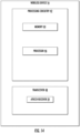
- FIG. 13 is a block diagram of an alternative embodiment of a network node 14 that includes a memory module 25, an sREG configuration module 19 and a transceiver module 29.
- the sREG configuration module 19 may be implemented in software executed by a processor to configure short resource element groups, sREGs, within a physical resource block, PRB.
- the transceiver module 29 may be implemented at least in part by software that may be executed by the processor to transmit the sPDCCH to the wireless device 16.
- FIG. 14 is a block diagram of a wireless device 16.
- the wireless device 16 has processing circuitry 42.
- the processing circuitry may include a memory 44 and processor 46, the memory 44 containing instructions which, when executed by the processor 46, configure processor 46 to perform the one or more functions described herein.
- processing circuitry 42 may comprise integrated circuitry for processing and/or control, e.g., one or more processors and/or processor cores and/or FPGAs (Field Programmable Gate Array) and/or ASICs (Application Specific Integrated Circuitry).
- Processing circuitry 42 may include and/or be connected to and/or be configured for accessing (e.g., writing to and/or reading from) memory 44, which may include any kind of volatile and/or non-volatile memory, e.g., cache and/or buffer memory and/or RAM (Random Access Memory) and/or ROM (Read-Only Memory) and/or optical memory and/or EPROM (Erasable Programmable Read-Only Memory).
- memory 44 may be configured to store code executable by control circuitry and/or other data, e.g., data pertaining to communication, e.g., configuration and/or address data of nodes, etc.
- Processing circuitry 42 may be configured to control any of the methods described herein and/or to cause such methods to be performed, e.g., by processor 46. Corresponding instructions may be stored in the memory 44, which may be readable and/or readably connected to the processing circuitry 42.
- processing circuitry 42 may include a controller, which may comprise a microprocessor and/or microcontroller and/or FPGA (Field-Programmable Gate Array) device and/or ASIC (Application Specific Integrated Circuit) device. It may be considered that processing circuitry 42 includes or may be connected or connectable to memory, which may be configured to be accessible for reading and/or writing by the controller and/or processing circuitry 42.
- the memory 44 is configured to store the sPDCCH.
- the wireless device 16 also includes a transceiver 48 which includes an sPDCCH receiver 50 configured to receive the sPDCCH from the network node 14 on one of a plurality of sets of PRBs.
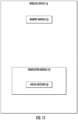
- FIG. 15 is a block diagram of an alternative embodiment of a wireless device 16 that includes a transceiver module 49 includes the sPDCCH receiver 50 which may be implemented in part by software executable by a processor.
- FIG. 16 is a flowchart of an exemplary process for mapping an sPDCCH to resource elements of a time-frequency grid.
- the process includes determining available time-frequency resources to be configured as sREGs (block S100).
- the process also includes configuring, via the sREG configuration unit 18, the sREGs within a PRB, to map the sPDCCH to the resource elements (block S102).
- the number of sREGs depending upon a number of OFDM symbols of a sPDCCH.
- the size of the sREG in the frequency domain is equal to 1 PRB which may be equal to 12 subcarriers.
- FIG. 17 is a flowchart of an exemplary process for mapping an sPDCCH to resource elements of a time-frequency grid.
- the process includes receiving, via the receiver 50, the sPDCCH from the network node 14 on one of a plurality of sets of PRBs (block S106).
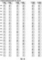
- distributed cases are defined and depicted in FIG. 18 , which shows a 1-OFDM symbol sPDCCH distributed scheme for a set of 18 PRBs.
- These cases include an aggregation level of up to 4 (i.e., up to 4 sCCE per sPDCCH). Higher aggregation levels are possible as well.
- These cases aim at regular distribution of the sREG over the PRBs of the configured PRB set in the frequency domain.
- Some embodiments have the features that the unused PRBs shown in FIG. 18 can be further assigned for building other sCCEs for other wireless devices 16. Further, these unused PRBs may be used for sPDSCH allocation.
- the PRB indices shown in FIG. 18 represent the number of the sREG group within the sPDCCH PRB set (for this example, a set of 18 PRBs). For simplicity, the physical PRB number is not shown.
- sREG group 0 or sREG group 1 in FIG. 18 can, as mentioned above, be signaled or calculated. It can also be standardized or signaled that the wireless device 16 should monitor a set of sREG, thereby increasing the search space but allowing for the network node 14 to send sPDCCH to multiple wireless devices 16 sharing the same set of configured PRBs.
- the aggregation levels (ALs) 2 (i.e. 2 sCCE) and 4 (i.e. 4 sCCE) comprise four cases. These cases are depicted in FIG. 18 , where areas in FIG. 18 that are shaded differently represent different sCCEs.
- Case 1 and Case 2 are the basis for all schemes. Therefore, in one embodiment, the Case 1 and Case 2 distribution schemes for 1 OFDM symbol sPDCCH can be achieved by the following formula.
- the above formula indicates the PRB number (location within the PRB set) of each sREG that builds up a sCCE by evenly distributing them over all available N sREG / PRB * N PRB sREG in the configured N PRB PRBs.
- a rougher granularity for the distribution and distribution of the sREGs over a sCCE evenly over the configured N PRB PRBs may be used. In this case, the equation becomes as follows.
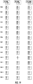
- the localized cases are defined and depicted in FIG. 19 , wherein differently shaded regions represent different sCCEs.
- options 1a and 1b correspond to 1 OFDM symbol sPDCCH.
- FIG. 19 shows a 1-OFDM symbol sPDCCH localized scheme.
- the sREGs building the same sCCE are localized in the frequency domain, i.e., in consecutive PRBs, to allow for a sPDCCH resource allocation confined in a limited frequency band.
- PRB based sREG as well as fractioned PRB based sREG.
- the PRB index shown in FIG. 19 represents the number of the sREG group within the sPDCCH PRB set (for this example, a set of 18 PRBs). For simplicity, the physical PRB number is not shown.
- the localized scheme cases i.e., 1L, 2L and 3L in FIG. 19
- 1 OFDM symbol sPDCCH can be achieved by the following algorithm:
- options 2a and 2b correspond to 2 OFDM symbol sPDCCH.
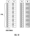
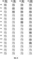
- the distributed cases are defined and depicted in FIG. 20 , which shows a 2-OFDM sPDCCH distributed scheme for a set of 19 PRBs. These cases comprise an aggregation level of up to 8 (i.e., up to 8 sCCE per sPDCCH) and a regular distribution in the frequency domain.
- This embodiment further assumes that the unused PRBs shown in FIG. 20 can be further assigned for building other sCCE for other wireless devices 16 following the description below as well as the possibility to be used for sPDSCH allocation. For simplicity, the physical PRB number is not shown.
- each differently shaded region represents a different sCCE:
- the PRB index shown in FIG. 22 represents the number within the sPDCCH PRB set (for this example, a set of 18 PRBs). For simplicity, the physical PRB number is not shown.
- one subframe cannot be divided into short TTIs each of length 2 symbols. Then, the subframe may be chosen such that one or more of the TTIs are in fact of length 3.
- the third symbol will have sREGs with index 4 and 5, extending case 2b of FIG. 10 . In another embodiment, the same number of sREGs are used, and the third symbol will have sREG with index 2 or3, identical to the second symbol in case 2b of FIG. 10 , and the sREG with index 2 and three will then consist of double number of REs
- mapping for sPDCCH to the resource elements (REs) is proposed.
- the mapping has various modes, each enabling exploitation of the channel or the advanced transmission modes. In one mode, large frequency diversity is achieved. In another mode condensed frequency allocation for a beamforming based transmission mode is enabled.
- the proposed mapping also can be extended to various number of OFDM symbols. With the proposed mapping, users with transmission modes relying on different reference signals, e.g. CRS and DMRS users, can coexist on the same sTTI.
- a method in network node 14 for mapping a short physical downlink control channel (sPDCCH) to resource elements of a time-frequency grid includes determining available time-frequency resources to be configured as short resource element groups (sREGs) (S100). The method also includes configuring sREGs within a physical resource block (PRB), to map the sPDCCH to the resource elements, each sREG spanning one OFDM symbol (S102).
- the spanning of one OFDM symbol refers to a time domain, e.g. the sREG is on a length of time of only one symbol.
- the sREG being within a PRB may refer to the sREG in the frequency domain, e.g. having a frequency extent or number of subcarriers which is one PRB.
- an sREG consists of 1 PRB within 1 OFDM symbol including REs for at least one of cell-specific reference signal (CRS), and demodulation reference signals (DMRS) applied to DMRS-based sPDCCH.
- CRS cell-specific reference signal
- DMRS demodulation reference signals
- an sREG consists of 1 PRB within 1 OFDM symbol including REs for at least one of CRS, and DMRS, applied to CRS-based sPDCCH.
- the sREGs are configured to be one of localized in a frequency domain (to facilitate beam forming) and distributed in the frequency domain (to achieve frequency diversity gain).
- the method further includes configuring a wireless device 16 by radio resource control (RRC) signaling to use a CRS, based sPDCCH resource block set with one of distributed or localized mapping of short control channel elements (sCCE), to sREGs.
- RRC radio resource control
- the method further includes configuring a wireless device 16 by RRC signaling to use a DMRS based sPDCCH resource block set with one of distributed or localized mapping of sCCE to sREGs.
- the method further includes configuring an sPDCCH PRB set with at least a set of PRBs and one of localized and distributed sCCE to sREG mapping.
- 1 OFDM symbol sPDCCH is defined for CRS based transmissions.
- a number of OFDM symbols per RB set is one of 1 and 2.
- a number of OFDM symbols per RB set is one of 1 and 2.
- a 2 OFDM symbol sPDCCH is defined for DMRS-based transmissions.
- a number of OFDM symbols per RB set is 2.
- a number of OFDM symbols per RB set is 3. In some embodiments, for DMRS based sPDCCH, with 1 slot sTTIs, a number of OFDM symbols per RB set is 2.
- a network node 14 for mapping a short physical downlink control channel, sPDCCH, to resource elements of a time-frequency grid.
- the network node 14 includes processing circuitry 22 configured to determine available time-frequency resources to be configured as short resource element groups, sREGs.
- the processing circuitry 22 is further configured to configure sREGs within a physical resource block, PRB, to map the sPDCCH to the resource elements, each sREG spanning one OFDM symbol.
- an sREG consists of 1 PRB within 1 OFDM symbol including REs for at least one of CRS and DMRS applied to DMRS-based sPDCCH. In some embodiments, an sREG consists of 1 PRB within 1 OFDM symbol including REs for at least one of CRS and DMRS applied to CRS-based sPDCCH. In some embodiments, the sREGs are configured to be one of localized in a frequency domain and distributed in the frequency domain. In some embodiments, the processing circuitry 22 is further configured to configure a wireless device 16 by RRC signaling to use a CRS based sPDCCH resource block set with one of distributed or localized mapping of short control channel elements (sCCE) to sREGs.
- sCCE short control channel elements
- the processing circuitry 22 is further configured to configure a wireless device 16 by RRC signaling to use a DMRS based sPDCCH resource block set with one of distributed or localized mapping of sCCE to sREGs.
- the distributed/localized mapping is of a plurality of sREGS (each being 1 PRB in frequency) to a sCCE.
- the processing circuitry 22 is further configured to configure an sPDCCH PRB set with at least a set of PRBs, and one of localized and distributed sCCE to sREG mapping.
- 1 OFDM symbol sPDCCH is defined for CRS based transmissions.
- a number of OFDM symbols per RB set is one of 1 and 2. In some embodiments, for CRS based sPDCCH, with 1 slot sTTI, a number of OFDM symbols per RB set is one of 1 and 2. In some embodiments, a 2 OFDM symbol sPDCCH is defined for DMRS-based transmissions. In some embodiments, for DMRS-based sPDCCH, with 2 sPDCCH symbol sTTI, a number of OFDM symbols per RB set is 2.
- a number of OFDM symbols per RB set is 3. In some embodiments, for DMRS-based sPDCCH, with 1 slot sTTI, a number of OFDM symbols per RB set is 2.
- a network node 14 for mapping a short physical downlink control channel (sPDCCH), to resource elements of a time-frequency grid to achieve one of high frequency diversity and condensed frequency allocation.
- the network node 14 includes a memory module 45 configured to store a mapping of the sPDCCH to resource elements of a time-frequency grid.
- the network node 14 further includes a short resource element group (sREG) configuration module 19 configured to configure sREGs within a physical resource block, PRB, to map the sPDCCH to the resource elements, each sREG spanning one OFDM symbol.
- sREG short resource element group
- a method in a wireless device 16 for receiving information on a short physical downlink control channel (sPDCCH) signaled by a network node 14, the sPDCCH being mapped to resource elements of a time-frequency grid, by configuring short resource element groups (sREGs) is provided.
- the method includes receiving the sPDCCH from the network node 14 on one of a plurality of sets of PRBs S106.
- the sPDCCH is of 2 OFDM symbols.
- the method further includes receiving an indication of a sequential order of PRBs from the network node 14.
- a wireless device 16 for receiving information on a short physical downlink control channel (sPDCCH) signaled by a network node 14, the sPDCCH being mapped to resource elements of a time-frequency grid, by configuring short resource element groups (sREGs) is provided.
- the wireless device 16 includes a transceiver 48 configured to receive the sPDCCH from the network node 14 on one of a plurality of sets of PRBs.
- the sPDCCH is of 2 OFDM symbols.
- the transceiver 48 is further configured to receive an indication of a sequential order of PRBs from the network node 14.
- a wireless device 16 for receiving information on a short physical downlink control channel (sPDCCH), signaled by a network node 14, the sPDCCH being mapped to resource elements of a time-frequency grid, by configuring short resource element groups (sREGs) is provided.
- the wireless device 16 includes a transceiver module 49 configured to receive the sPDCCH from the network node 14 on one of a plurality of sets of PRBs.
Landscapes
- Engineering & Computer Science (AREA)
- Signal Processing (AREA)
- Computer Networks & Wireless Communication (AREA)
- Mobile Radio Communication Systems (AREA)
- Radio Transmission System (AREA)
Applications Claiming Priority (3)
| Application Number | Priority Date | Filing Date | Title |
|---|---|---|---|
| US201662418063P | 2016-11-04 | 2016-11-04 | |
| EP17793946.9A EP3491770B1 (en) | 2016-11-04 | 2017-11-03 | Short physical downlink control channel (spdcch) mapping design |
| PCT/EP2017/078219 WO2018083260A1 (en) | 2016-11-04 | 2017-11-03 | Short physical downlink control channel (spdcch) mapping design |
Related Parent Applications (2)
| Application Number | Title | Priority Date | Filing Date |
|---|---|---|---|
| EP17793946.9A Division-Into EP3491770B1 (en) | 2016-11-04 | 2017-11-03 | Short physical downlink control channel (spdcch) mapping design |
| EP17793946.9A Division EP3491770B1 (en) | 2016-11-04 | 2017-11-03 | Short physical downlink control channel (spdcch) mapping design |
Publications (2)
| Publication Number | Publication Date |
|---|---|
| EP3681084A1 EP3681084A1 (en) | 2020-07-15 |
| EP3681084B1 true EP3681084B1 (en) | 2024-04-17 |
Family
ID=60245103
Family Applications (2)
| Application Number | Title | Priority Date | Filing Date |
|---|---|---|---|
| EP19206593.6A Active EP3681084B1 (en) | 2016-11-04 | 2017-11-03 | Short physical downlink control channel (spdcch) mapping design |
| EP17793946.9A Active EP3491770B1 (en) | 2016-11-04 | 2017-11-03 | Short physical downlink control channel (spdcch) mapping design |
Family Applications After (1)
| Application Number | Title | Priority Date | Filing Date |
|---|---|---|---|
| EP17793946.9A Active EP3491770B1 (en) | 2016-11-04 | 2017-11-03 | Short physical downlink control channel (spdcch) mapping design |
Country Status (15)
| Country | Link |
|---|---|
| US (2) | US11323224B2 (es) |
| EP (2) | EP3681084B1 (es) |
| JP (2) | JP7022744B2 (es) |
| KR (1) | KR102261777B1 (es) |
| CN (1) | CN109891816B (es) |
| BR (1) | BR112019007319A2 (es) |
| CL (1) | CL2019001112A1 (es) |
| CO (1) | CO2019003966A2 (es) |
| DK (1) | DK3491770T3 (es) |
| ES (1) | ES2775791T3 (es) |
| MX (1) | MX2019005179A (es) |
| PL (1) | PL3491770T3 (es) |
| PT (1) | PT3491770T (es) |
| WO (1) | WO2018083260A1 (es) |
| ZA (1) | ZA201901998B (es) |
Families Citing this family (9)
| Publication number | Priority date | Publication date | Assignee | Title |
|---|---|---|---|---|
| EP3681084B1 (en) | 2016-11-04 | 2024-04-17 | Telefonaktiebolaget LM Ericsson (publ) | Short physical downlink control channel (spdcch) mapping design |
| HUE053211T2 (hu) * | 2016-12-19 | 2021-06-28 | Guangdong Oppo Mobile Telecommunications Corp Ltd | Eljárás információ átvitelére, hálózati berendezés és végberendezés |
| US11533716B2 (en) | 2017-08-11 | 2022-12-20 | Telefonaktiebolaget Lm Ericsson (Publ) | Flexible short Transmission Time Interval (TTI) resource allocation |
| WO2019030346A1 (en) | 2017-08-11 | 2019-02-14 | Telefonaktiebolaget Lm Ericsson (Publ) | ASSIGNMENT OF PHYSICAL SHORT LINK CONTROL (SPDCCH) PHYSICAL CHANNELS FOR SHORT TRANSMISSION TIME INTERVAL (STTI) |
| JP7059365B2 (ja) | 2017-09-29 | 2022-04-25 | テレフオンアクチーボラゲット エルエム エリクソン(パブル) | ショート物理ダウンリンク制御チャネル(spdcch)のための、ショート制御チャネルエレメント(scce)とショートリソースエレメントグループ(sreg)とのマッピング |
| US11303404B2 (en) * | 2017-11-14 | 2022-04-12 | Qualcomm Incorporated | Demodulation reference signal transmission |
| US11569957B2 (en) | 2019-08-16 | 2023-01-31 | Samsung Electronics Co., Ltd. | Method and apparatus for transmitting and receiving downlink control channel in shortened transmission time intervals |
| CN110519191B (zh) * | 2019-09-22 | 2021-04-30 | 电子科技大学 | 一种时频二维压缩的高谱效单载波通信方法 |
| WO2023123097A1 (zh) * | 2021-12-29 | 2023-07-06 | 北京小米移动软件有限公司 | 资源元素群组捆确定、映射方法和装置 |
Citations (1)
| Publication number | Priority date | Publication date | Assignee | Title |
|---|---|---|---|---|
| EP3439396A1 (en) * | 2016-03-31 | 2019-02-06 | Sony Corporation | Terminal device, base station device and communication method |
Family Cites Families (58)
| Publication number | Priority date | Publication date | Assignee | Title |
|---|---|---|---|---|
| KR101376233B1 (ko) * | 2007-10-02 | 2014-03-21 | 삼성전자주식회사 | 주파수 분할 다중 접속 방식의 시스템에서 제어 채널의자원 할당 장치 및 방법 |
| US20100097937A1 (en) | 2008-10-16 | 2010-04-22 | Interdigital Patent Holdings, Inc. | Method and apparatus for wireless transmit/receive unit specific pilot signal transmission and wireless transmit/receive unit specific pilot signal power boosting |
| US20110200004A1 (en) * | 2008-10-29 | 2011-08-18 | Daiichiro Nakashima | Wireless communication system, mobile station device, and base station device |
| KR101603108B1 (ko) * | 2008-11-07 | 2016-03-14 | 엘지전자 주식회사 | 참조 신호 전송 방법 |
| JP2011030092A (ja) * | 2009-07-28 | 2011-02-10 | Kyocera Corp | 無線基地局及び通信制御方法 |
| CN102036380B (zh) * | 2009-09-27 | 2013-07-31 | 电信科学技术研究院 | 一种接收下行反馈信息的方法、系统和装置 |
| KR101053635B1 (ko) * | 2010-01-28 | 2011-08-03 | 엘지전자 주식회사 | 다중 안테나 무선 통신 시스템에서 기지국이 릴레이 노드로 제어 신호를 송신하는 방법 및 이를 위한 장치 |
| US20130201926A1 (en) * | 2011-08-11 | 2013-08-08 | Samsung Electronics Co., Ltd. | System and method for physical downlink control and hybrid-arq indicator channels in lte-a systems |
| US9031033B2 (en) * | 2011-09-27 | 2015-05-12 | Apple Inc. | Wireless radio access network control channel capacity management |
| US9402264B2 (en) | 2011-09-30 | 2016-07-26 | Intel Corporation | Methods to transport internet traffic over multiple wireless networks simultaneously |
| EP2590350A1 (en) * | 2011-11-07 | 2013-05-08 | Panasonic Corporation | Enhanced PDCCH overlapping with the PDCCH region |
| US9467991B2 (en) * | 2011-11-23 | 2016-10-11 | Lg Electronics Inc. | Methods and apparatuses for transmitting and receiving downlink control channel in wireless communication system |
| WO2013077661A1 (ko) * | 2011-11-25 | 2013-05-30 | 엘지전자 주식회사 | 무선 통신 시스템에서 채널 품질 지시자를 측정하는 방법 및 장치 |
| US9572148B2 (en) * | 2011-12-07 | 2017-02-14 | Lg Electronics Inc. | Method and apparatus for transceiving a downlink control channel in a wireless communication system |
| CN102546134B (zh) * | 2011-12-29 | 2015-07-22 | 电信科学技术研究院 | 基于增强phich传输反馈信息的方法及装置 |
| CN104054293B (zh) * | 2012-01-18 | 2017-10-24 | Lg电子株式会社 | 无线通信系统中用于基于增强型控制信道的操作的方法和设备 |
| KR101959398B1 (ko) * | 2012-01-25 | 2019-03-18 | 삼성전자주식회사 | 직교 주파수 분할 다중 통신 시스템에서 제어 채널 신호 전송 방법 및 장치 |
| US8798010B2 (en) * | 2012-01-31 | 2014-08-05 | Lsi Corporation | Table-based resource mapping for downlink control channels in a wireless system base station |
| WO2013129866A1 (ko) * | 2012-02-29 | 2013-09-06 | 엘지전자 주식회사 | 캐리어 타입을 고려한 통신 방법 및 이를 위한 장치 |
| US9526091B2 (en) * | 2012-03-16 | 2016-12-20 | Intel Corporation | Method and apparatus for coordination of self-optimization functions in a wireless network |
| US9198181B2 (en) * | 2012-03-19 | 2015-11-24 | Blackberry Limited | Enhanced common downlink control channels |
| CN104272614B (zh) * | 2012-03-28 | 2017-06-23 | Lg电子株式会社 | 在无线通信系统中分配用于下行链路控制信道的资源的方法 |
| WO2013151339A1 (ko) * | 2012-04-03 | 2013-10-10 | 엘지전자 주식회사 | 캐리어 타입을 고려한 통신 방법 및 이를 위한 장치 |
| CN102665230B (zh) * | 2012-04-23 | 2014-07-09 | 电信科学技术研究院 | 一种e-pdcch传输及盲检的方法及装置 |
| US20150181568A1 (en) * | 2012-06-05 | 2015-06-25 | Lg Electronics Inc. | Method and apparatus for receiving control information in wireless communication system |
| JP5990793B2 (ja) * | 2012-06-07 | 2016-09-14 | シャープ株式会社 | 端末装置、基地局装置、通信方法および集積回路 |
| US9854571B2 (en) * | 2012-07-23 | 2017-12-26 | Lg Electronics Inc. | Method and apparatus for acquiring diversity gain according to distributed resource allocation for downlink control channel in wireless communication system |
| JP5829987B2 (ja) * | 2012-07-23 | 2015-12-09 | 株式会社Nttドコモ | 無線通信方法、無線通信システム及び無線基地局 |
| JP6143153B2 (ja) * | 2012-08-01 | 2017-06-07 | シャープ株式会社 | 基地局、端末、通信方法および集積回路 |
| US9131498B2 (en) | 2012-09-12 | 2015-09-08 | Futurewei Technologies, Inc. | System and method for adaptive transmission time interval (TTI) structure |
| JP6179009B2 (ja) * | 2012-09-20 | 2017-08-16 | シャープ株式会社 | 端末装置、基地局装置、無線通信方法、および集積回路 |
| JP6068653B2 (ja) | 2012-09-28 | 2017-01-25 | テレフオンアクチーボラゲット エルエム エリクソン(パブル) | ePDCCHを通信するための、無線ネットワークにおける方法、ネットワークノード、及びユーザ端末 |
| WO2014054887A1 (ko) * | 2012-10-02 | 2014-04-10 | 한양대학교 산학협력단 | 하향링크 신호 및 채널의 전송방법 및 수신방법, 그 단말, 그 기지국 |
| US9307521B2 (en) * | 2012-11-01 | 2016-04-05 | Samsung Electronics Co., Ltd. | Transmission scheme and quasi co-location assumption of antenna ports for PDSCH of transmission mode 10 for LTE advanced |
| CN103795509A (zh) * | 2012-11-02 | 2014-05-14 | 北京三星通信技术研究有限公司 | 一种传输harq指示信息的方法和设备 |
| MX346311B (es) * | 2012-11-05 | 2017-03-15 | Sharp Kk * | Dispositivo terminal, circuito integrado, método de radiocomunicación, y dispositivo de estación base. |
| CN104782206B (zh) * | 2012-11-09 | 2018-06-29 | 夏普株式会社 | 终端装置、通信方法以及集成电路 |
| WO2014077608A1 (ko) * | 2012-11-14 | 2014-05-22 | 엘지전자 주식회사 | 하향링크 제어채널 모니터링 방법 및 장치 |
| CN103944692A (zh) * | 2013-01-18 | 2014-07-23 | 中兴通讯股份有限公司 | ePHICH的发送方法及装置、接收方法及装置 |
| US9775161B2 (en) * | 2013-03-18 | 2017-09-26 | Nec Corporation | Method for PHICH resource allocation |
| CN103179670B (zh) * | 2013-04-03 | 2016-08-24 | 华为技术有限公司 | 传输信道的方法及其装置 |
| WO2014185674A1 (ko) * | 2013-05-11 | 2014-11-20 | 엘지전자 주식회사 | 캐리어 타입을 고려한 통신 방법 및 이를 위한 장치 |
| US10034278B2 (en) * | 2013-05-21 | 2018-07-24 | Telefonaktiebolaget L M Ericsson (Publ) | Method and device for handling different DCI messages in a wireless network node of a cellular communication system providing multiple bandwidths |
| US20160174247A1 (en) * | 2013-08-06 | 2016-06-16 | Sharp Kabushiki Kaisha | Terminal apparatus, base station apparatus, communication system, communication method, and integrated circuit |
| US20150173102A1 (en) * | 2013-12-12 | 2015-06-18 | Sharp Kabushiki Kaisha | Terminal apparatus, base station apparatus, communication system, communication method, and integrated circuit |
| US9621310B2 (en) | 2013-12-23 | 2017-04-11 | Apple Inc. | TTI bundling for downlink communication |
| WO2016064039A1 (ko) * | 2014-10-21 | 2016-04-28 | 엘지전자(주) | 저 지연을 지원하는 무선 통신 시스템에서 데이터 송수신 방법 및 이를 위한 장치 |
| US9647864B2 (en) * | 2015-04-10 | 2017-05-09 | Motorola Mobility Llc | Method and apparatus for reception of control signaling |
| US10250420B2 (en) * | 2015-04-10 | 2019-04-02 | Motorola Mobility Llc | Method and apparatus for reception of control signaling |
| US10085158B2 (en) * | 2015-05-14 | 2018-09-25 | Sharp Laboratories Of America, Inc. | User equipments, base stations and methods |
| US20180192420A1 (en) * | 2015-07-02 | 2018-07-05 | Nokia Solutions And Networks Oy | Method, apparatus and system |
| CN106686603B (zh) * | 2015-11-05 | 2020-11-20 | 中兴通讯股份有限公司 | 信道干净评估检测方法和装置 |
| EP3398284B1 (en) * | 2015-12-30 | 2020-05-27 | Telefonaktiebolaget LM Ericsson (PUBL) | Methods and devices for cell edge robustness of pdcch |
| CN108432198B (zh) * | 2016-01-11 | 2021-07-23 | 苹果公司 | 用于IoT控制信道的装置和方法 |
| KR102364679B1 (ko) * | 2016-01-13 | 2022-02-18 | 엘지전자 주식회사 | 상향링크 데이터 전송 방법 및 사용자기기와, 상향링크 데이터 수신 방법 및 기지국 |
| WO2017192224A1 (en) * | 2016-05-04 | 2017-11-09 | Intel IP Corporation | Downlink control channel transmissions |
| CN107707340B (zh) * | 2016-08-09 | 2021-03-09 | 电信科学技术研究院 | 信道资源确定、资源映射方法及装置 |
| EP3681084B1 (en) | 2016-11-04 | 2024-04-17 | Telefonaktiebolaget LM Ericsson (publ) | Short physical downlink control channel (spdcch) mapping design |
-
2017
- 2017-11-03 EP EP19206593.6A patent/EP3681084B1/en active Active
- 2017-11-03 DK DK17793946.9T patent/DK3491770T3/da active
- 2017-11-03 PT PT177939469T patent/PT3491770T/pt unknown
- 2017-11-03 JP JP2019517211A patent/JP7022744B2/ja active Active
- 2017-11-03 CN CN201780068464.8A patent/CN109891816B/zh active Active
- 2017-11-03 PL PL17793946T patent/PL3491770T3/pl unknown
- 2017-11-03 BR BR112019007319A patent/BR112019007319A2/pt unknown
- 2017-11-03 EP EP17793946.9A patent/EP3491770B1/en active Active
- 2017-11-03 MX MX2019005179A patent/MX2019005179A/es unknown
- 2017-11-03 KR KR1020197012704A patent/KR102261777B1/ko active IP Right Grant
- 2017-11-03 WO PCT/EP2017/078219 patent/WO2018083260A1/en unknown
- 2017-11-03 ES ES17793946T patent/ES2775791T3/es active Active
-
2019
- 2019-02-22 US US16/283,056 patent/US11323224B2/en active Active
- 2019-03-29 ZA ZA2019/01998A patent/ZA201901998B/en unknown
- 2019-04-22 CO CONC2019/0003966A patent/CO2019003966A2/es unknown
- 2019-04-23 CL CL2019001112A patent/CL2019001112A1/es unknown
-
2022
- 2022-02-07 JP JP2022017204A patent/JP7324886B2/ja active Active
- 2022-04-05 US US17/713,792 patent/US11949619B2/en active Active
Patent Citations (1)
| Publication number | Priority date | Publication date | Assignee | Title |
|---|---|---|---|---|
| EP3439396A1 (en) * | 2016-03-31 | 2019-02-06 | Sony Corporation | Terminal device, base station device and communication method |
Also Published As
| Publication number | Publication date |
|---|---|
| DK3491770T3 (da) | 2020-04-14 |
| PL3491770T3 (pl) | 2020-07-27 |
| CL2019001112A1 (es) | 2019-07-05 |
| MX2019005179A (es) | 2019-08-05 |
| US20220239421A1 (en) | 2022-07-28 |
| PT3491770T (pt) | 2020-03-25 |
| EP3491770B1 (en) | 2020-01-08 |
| EP3491770A1 (en) | 2019-06-05 |
| JP7022744B2 (ja) | 2022-02-18 |
| CO2019003966A2 (es) | 2019-04-30 |
| US20190260525A1 (en) | 2019-08-22 |
| US11323224B2 (en) | 2022-05-03 |
| KR20190056437A (ko) | 2019-05-24 |
| JP2022078051A (ja) | 2022-05-24 |
| WO2018083260A1 (en) | 2018-05-11 |
| ZA201901998B (en) | 2020-08-26 |
| US11949619B2 (en) | 2024-04-02 |
| JP7324886B2 (ja) | 2023-08-10 |
| KR102261777B1 (ko) | 2021-06-08 |
| EP3681084A1 (en) | 2020-07-15 |
| BR112019007319A2 (pt) | 2019-07-02 |
| CN109891816A (zh) | 2019-06-14 |
| ES2775791T3 (es) | 2020-07-28 |
| CN109891816B (zh) | 2021-11-09 |
| JP2020502844A (ja) | 2020-01-23 |
| CN113922941A (zh) | 2022-01-11 |
Similar Documents
| Publication | Publication Date | Title |
|---|---|---|
| EP3681084B1 (en) | Short physical downlink control channel (spdcch) mapping design | |
| KR102207809B1 (ko) | 무선 통신 시스템에서 자원 할당 방법 및 상기 방법을 이용하는 장치 | |
| US10805913B2 (en) | Method and user equipment for receiving donwlink signal, method and base station for transmitting downlink signal | |
| US20170317794A1 (en) | Method and user equipment for transmitting uplink signal, and method and base station for receiving uplink signal | |
| EP3455991B1 (en) | Configuration of downlink transmissions | |
| US11432272B2 (en) | Assignment of short physical downlink control channel (sPDCCH) candidates for short transmission time interval (sTTI) | |
| EP3665828B1 (en) | Flexible short transmission time interval (tti) resource allocation | |
| CN115767750A (zh) | 用于下行链路控制物理结构的方法和设备 | |
| US11902193B2 (en) | Search space configuration for short transmission time interval | |
| EP3577973B1 (en) | Dynamic short physical downlink control channel (spdcch) resources determination | |
| CN113922941B (zh) | 短物理下行链路控制信道(sPDCCH)映射设计 |
Legal Events
| Date | Code | Title | Description |
|---|---|---|---|
| PUAI | Public reference made under article 153(3) epc to a published international application that has entered the european phase |
Free format text: ORIGINAL CODE: 0009012 |
|
| STAA | Information on the status of an ep patent application or granted ep patent |
Free format text: STATUS: THE APPLICATION HAS BEEN PUBLISHED |
|
| AC | Divisional application: reference to earlier application |
Ref document number: 3491770 Country of ref document: EP Kind code of ref document: P |
|
| AK | Designated contracting states |
Kind code of ref document: A1 Designated state(s): AL AT BE BG CH CY CZ DE DK EE ES FI FR GB GR HR HU IE IS IT LI LT LU LV MC MK MT NL NO PL PT RO RS SE SI SK SM TR |
|
| STAA | Information on the status of an ep patent application or granted ep patent |
Free format text: STATUS: REQUEST FOR EXAMINATION WAS MADE |
|
| 17P | Request for examination filed |
Effective date: 20210115 |
|
| RBV | Designated contracting states (corrected) |
Designated state(s): AL AT BE BG CH CY CZ DE DK EE ES FI FR GB GR HR HU IE IS IT LI LT LU LV MC MK MT NL NO PL PT RO RS SE SI SK SM TR |
|
| STAA | Information on the status of an ep patent application or granted ep patent |
Free format text: STATUS: EXAMINATION IS IN PROGRESS |
|
| 17Q | First examination report despatched |
Effective date: 20210521 |
|
| GRAP | Despatch of communication of intention to grant a patent |
Free format text: ORIGINAL CODE: EPIDOSNIGR1 |
|
| STAA | Information on the status of an ep patent application or granted ep patent |
Free format text: STATUS: GRANT OF PATENT IS INTENDED |
|
| INTG | Intention to grant announced |
Effective date: 20221117 |
|
| RIN1 | Information on inventor provided before grant (corrected) |
Inventor name: FALCONETTI, LAETITIA Inventor name: ANDGART, NIKLAS Inventor name: SOLANO ARENAS, JOHN CAMILO |
|
| GRAJ | Information related to disapproval of communication of intention to grant by the applicant or resumption of examination proceedings by the epo deleted |
Free format text: ORIGINAL CODE: EPIDOSDIGR1 |
|
| STAA | Information on the status of an ep patent application or granted ep patent |
Free format text: STATUS: EXAMINATION IS IN PROGRESS |
|
| GRAJ | Information related to disapproval of communication of intention to grant by the applicant or resumption of examination proceedings by the epo deleted |
Free format text: ORIGINAL CODE: EPIDOSDIGR1 |
|
| GRAL | Information related to payment of fee for publishing/printing deleted |
Free format text: ORIGINAL CODE: EPIDOSDIGR3 |
|
| GRAS | Grant fee paid |
Free format text: ORIGINAL CODE: EPIDOSNIGR3 |
|
| INTC | Intention to grant announced (deleted) | ||
| GRAP | Despatch of communication of intention to grant a patent |
Free format text: ORIGINAL CODE: EPIDOSNIGR1 |
|
| STAA | Information on the status of an ep patent application or granted ep patent |
Free format text: STATUS: GRANT OF PATENT IS INTENDED |
|
| INTG | Intention to grant announced |
Effective date: 20230504 |
|
| GRAJ | Information related to disapproval of communication of intention to grant by the applicant or resumption of examination proceedings by the epo deleted |
Free format text: ORIGINAL CODE: EPIDOSDIGR1 |
|
| STAA | Information on the status of an ep patent application or granted ep patent |
Free format text: STATUS: EXAMINATION IS IN PROGRESS |
|
| INTC | Intention to grant announced (deleted) | ||
| GRAP | Despatch of communication of intention to grant a patent |
Free format text: ORIGINAL CODE: EPIDOSNIGR1 |
|
| STAA | Information on the status of an ep patent application or granted ep patent |
Free format text: STATUS: GRANT OF PATENT IS INTENDED |
|
| INTG | Intention to grant announced |
Effective date: 20231027 |
|
| GRAS | Grant fee paid |
Free format text: ORIGINAL CODE: EPIDOSNIGR3 |
|
| GRAA | (expected) grant |
Free format text: ORIGINAL CODE: 0009210 |
|
| STAA | Information on the status of an ep patent application or granted ep patent |
Free format text: STATUS: THE PATENT HAS BEEN GRANTED |
|
| AC | Divisional application: reference to earlier application |
Ref document number: 3491770 Country of ref document: EP Kind code of ref document: P |
|
| AK | Designated contracting states |
Kind code of ref document: B1 Designated state(s): AL AT BE BG CH CY CZ DE DK EE ES FI FR GB GR HR HU IE IS IT LI LT LU LV MC MK MT NL NO PL PT RO RS SE SI SK SM TR |
|
| REG | Reference to a national code |
Ref country code: GB Ref legal event code: FG4D |
|
| REG | Reference to a national code |
Ref country code: CH Ref legal event code: EP |
|
| REG | Reference to a national code |
Ref country code: DE Ref legal event code: R096 Ref document number: 602017081195 Country of ref document: DE |
|
| REG | Reference to a national code |
Ref country code: IE Ref legal event code: FG4D |