EP3681014A1 - Consequent pole-type motor, electric motor, compressor, air blower, and air conditioner - Google Patents
Consequent pole-type motor, electric motor, compressor, air blower, and air conditioner Download PDFInfo
- Publication number
- EP3681014A1 EP3681014A1 EP17924439.7A EP17924439A EP3681014A1 EP 3681014 A1 EP3681014 A1 EP 3681014A1 EP 17924439 A EP17924439 A EP 17924439A EP 3681014 A1 EP3681014 A1 EP 3681014A1
- Authority
- EP
- European Patent Office
- Prior art keywords
- insertion hole
- opening
- magnet insertion
- consequent
- region
- Prior art date
- Legal status (The legal status is an assumption and is not a legal conclusion. Google has not performed a legal analysis and makes no representation as to the accuracy of the status listed.)
- Granted
Links
Images



Classifications
-
- H—ELECTRICITY
- H02—GENERATION; CONVERSION OR DISTRIBUTION OF ELECTRIC POWER
- H02K—DYNAMO-ELECTRIC MACHINES
- H02K1/00—Details of the magnetic circuit
- H02K1/06—Details of the magnetic circuit characterised by the shape, form or construction
- H02K1/22—Rotating parts of the magnetic circuit
- H02K1/27—Rotor cores with permanent magnets
- H02K1/2706—Inner rotors
- H02K1/272—Inner rotors the magnetisation axis of the magnets being perpendicular to the rotor axis
- H02K1/274—Inner rotors the magnetisation axis of the magnets being perpendicular to the rotor axis the rotor consisting of two or more circumferentially positioned magnets
- H02K1/2746—Inner rotors the magnetisation axis of the magnets being perpendicular to the rotor axis the rotor consisting of two or more circumferentially positioned magnets the rotor consisting of magnets arranged with the same polarity, e.g. consequent pole type
-
- H—ELECTRICITY
- H02—GENERATION; CONVERSION OR DISTRIBUTION OF ELECTRIC POWER
- H02K—DYNAMO-ELECTRIC MACHINES
- H02K1/00—Details of the magnetic circuit
- H02K1/06—Details of the magnetic circuit characterised by the shape, form or construction
- H02K1/22—Rotating parts of the magnetic circuit
- H02K1/27—Rotor cores with permanent magnets
- H02K1/2706—Inner rotors
- H02K1/272—Inner rotors the magnetisation axis of the magnets being perpendicular to the rotor axis
- H02K1/274—Inner rotors the magnetisation axis of the magnets being perpendicular to the rotor axis the rotor consisting of two or more circumferentially positioned magnets
- H02K1/2753—Inner rotors the magnetisation axis of the magnets being perpendicular to the rotor axis the rotor consisting of two or more circumferentially positioned magnets the rotor consisting of magnets or groups of magnets arranged with alternating polarity
- H02K1/276—Magnets embedded in the magnetic core, e.g. interior permanent magnets [IPM]
-
- F—MECHANICAL ENGINEERING; LIGHTING; HEATING; WEAPONS; BLASTING
- F04—POSITIVE - DISPLACEMENT MACHINES FOR LIQUIDS; PUMPS FOR LIQUIDS OR ELASTIC FLUIDS
- F04B—POSITIVE-DISPLACEMENT MACHINES FOR LIQUIDS; PUMPS
- F04B35/00—Piston pumps specially adapted for elastic fluids and characterised by the driving means to their working members, or by combination with, or adaptation to, specific driving engines or motors, not otherwise provided for
- F04B35/04—Piston pumps specially adapted for elastic fluids and characterised by the driving means to their working members, or by combination with, or adaptation to, specific driving engines or motors, not otherwise provided for the means being electric
-
- F—MECHANICAL ENGINEERING; LIGHTING; HEATING; WEAPONS; BLASTING
- F04—POSITIVE - DISPLACEMENT MACHINES FOR LIQUIDS; PUMPS FOR LIQUIDS OR ELASTIC FLUIDS
- F04D—NON-POSITIVE-DISPLACEMENT PUMPS
- F04D25/00—Pumping installations or systems
- F04D25/02—Units comprising pumps and their driving means
- F04D25/08—Units comprising pumps and their driving means the working fluid being air, e.g. for ventilation
-
- F—MECHANICAL ENGINEERING; LIGHTING; HEATING; WEAPONS; BLASTING
- F24—HEATING; RANGES; VENTILATING
- F24F—AIR-CONDITIONING; AIR-HUMIDIFICATION; VENTILATION; USE OF AIR CURRENTS FOR SCREENING
- F24F1/00—Room units for air-conditioning, e.g. separate or self-contained units or units receiving primary air from a central station
- F24F1/0007—Indoor units, e.g. fan coil units
- F24F1/0018—Indoor units, e.g. fan coil units characterised by fans
-
- F—MECHANICAL ENGINEERING; LIGHTING; HEATING; WEAPONS; BLASTING
- F24—HEATING; RANGES; VENTILATING
- F24F—AIR-CONDITIONING; AIR-HUMIDIFICATION; VENTILATION; USE OF AIR CURRENTS FOR SCREENING
- F24F1/00—Room units for air-conditioning, e.g. separate or self-contained units or units receiving primary air from a central station
- F24F1/06—Separate outdoor units, e.g. outdoor unit to be linked to a separate room comprising a compressor and a heat exchanger
- F24F1/20—Electric components for separate outdoor units
-
- F—MECHANICAL ENGINEERING; LIGHTING; HEATING; WEAPONS; BLASTING
- F24—HEATING; RANGES; VENTILATING
- F24F—AIR-CONDITIONING; AIR-HUMIDIFICATION; VENTILATION; USE OF AIR CURRENTS FOR SCREENING
- F24F13/00—Details common to, or for air-conditioning, air-humidification, ventilation or use of air currents for screening
- F24F13/24—Means for preventing or suppressing noise
-
- F—MECHANICAL ENGINEERING; LIGHTING; HEATING; WEAPONS; BLASTING
- F25—REFRIGERATION OR COOLING; COMBINED HEATING AND REFRIGERATION SYSTEMS; HEAT PUMP SYSTEMS; MANUFACTURE OR STORAGE OF ICE; LIQUEFACTION SOLIDIFICATION OF GASES
- F25B—REFRIGERATION MACHINES, PLANTS OR SYSTEMS; COMBINED HEATING AND REFRIGERATION SYSTEMS; HEAT PUMP SYSTEMS
- F25B31/00—Compressor arrangements
- F25B31/02—Compressor arrangements of motor-compressor units
-
- H—ELECTRICITY
- H02—GENERATION; CONVERSION OR DISTRIBUTION OF ELECTRIC POWER
- H02K—DYNAMO-ELECTRIC MACHINES
- H02K1/00—Details of the magnetic circuit
- H02K1/06—Details of the magnetic circuit characterised by the shape, form or construction
- H02K1/22—Rotating parts of the magnetic circuit
- H02K1/24—Rotor cores with salient poles ; Variable reluctance rotors
- H02K1/246—Variable reluctance rotors
-
- H—ELECTRICITY
- H02—GENERATION; CONVERSION OR DISTRIBUTION OF ELECTRIC POWER
- H02K—DYNAMO-ELECTRIC MACHINES
- H02K21/00—Synchronous motors having permanent magnets; Synchronous generators having permanent magnets
- H02K21/12—Synchronous motors having permanent magnets; Synchronous generators having permanent magnets with stationary armatures and rotating magnets
- H02K21/14—Synchronous motors having permanent magnets; Synchronous generators having permanent magnets with stationary armatures and rotating magnets with magnets rotating within the armatures
-
- H—ELECTRICITY
- H02—GENERATION; CONVERSION OR DISTRIBUTION OF ELECTRIC POWER
- H02K—DYNAMO-ELECTRIC MACHINES
- H02K2213/00—Specific aspects, not otherwise provided for and not covered by codes H02K2201/00 - H02K2211/00
- H02K2213/03—Machines characterised by numerical values, ranges, mathematical expressions or similar information
Definitions
- the present invention relates to a rotor used for an electric motor, and in particular, to a consequent-pole type rotor.
- Consequent-pole type rotors are being used as rotors of electric motors.
- the consequent-pole type rotor is divided into regions each including a permanent magnet and regions including no permanent magnet.
- a region including a permanent magnet functions as one magnetic pole (e.g., a magnetic pole functioning as a north pole for a stator), and a region between permanent magnets adjacent to each other in a circumferential direction functions as the other magnetic pole (e.g., a pseudo-magnetic pole functioning as a south pole for the stator) (see Patent Reference 1, for example).
- Patent Reference 1 Japanese Patent Application Publication No. 8-182267
- An object of the present invention is to reduce the noise in an electric motor.
- a consequent-pole type rotor is a consequent-pole type rotor including a first magnetic pole and a second magnetic pole, including: a rotor core including a magnet insertion hole and an opening formed inside the magnet insertion hole in a radial direction; and a permanent magnet inserted in the magnet insertion hole and forming the first magnetic pole.
- the consequent-pole type rotor satisfies L1 ⁇ L2, where L1 is a first maximum width of the opening in a direction perpendicular to the radial direction and L2 is a second maximum width of the opening in the radial direction. A distance from the opening to the magnet insertion hole is smallest at a magnetic pole center of the first magnetic pole.
- noise in an electric motor can be reduced.
- a z-axis direction represents a direction parallel to an axis line A1 of a shaft 23 of the electric motor 1 (hereinafter referred to as an "axial direction")
- an x-axis direction represents a direction perpendicular to the z-axis direction (z-axis)
- a y-axis direction represents a direction perpendicular to both the z-axis direction and the x-axis direction.
- Fig. 1 is a partially sectional view schematically showing a structure of the electric motor 1 according to the first embodiment of the present invention.
- Fig. 2 is a front view schematically showing the structure of the electric motor 1.
- the electric motor 1 includes a rotor 2, a stator 3, a circuit board 4, a magnetic sensor 5 that detects a rotational position of the rotor 2, a bracket 6, bearings 7a and 7b, and a sensor magnet 8 as a magnet for detecting the position of the rotor 2.
- the electric motor 1 is a permanent magnet synchronous motor, for example.
- the circuit board 4 is provided on a side of the stator 3 at one end in the axial direction. Electronic components such as a control circuit and the magnetic sensor 5 are attached to the circuit board 4.
- the magnetic sensor 5 detects the rotational position of the rotor 2 by detecting a rotational position of the sensor magnet 8.
- the sensor magnet 8 is attached to the rotor 2 to face the magnetic sensor 5.
- the sensor magnet 8 is disk-shaped, for example. The sensor magnet 8 rotates together with the rotor 2.
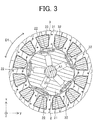
- Fig. 3 is a cross-sectional view schematically showing a structure of the rotor 2 and the stator 3.
- the arrow D1 shows a circumferential direction of a rotor core 21, the rotor 2 and the stator 3 (hereinafter referred to simply as "the circumferential direction"). Namely, the arrow D1 shows a direction along an outer circumference of the rotor core 21 and the rotor 2.
- the stator 3 includes a stator core 31, a coil 32 and an insulator 33.
- the stator core 31 is formed by, for example, stacking a plurality of electromagnetic steel sheets.
- the thickness of each electromagnetic steel sheet is 0.2 mm to 0.5 mm, for example.
- the stator core 31 is formed in a ring-like shape.
- the coil 32 is formed by, for example, winging a winding (e.g., magnet wire) around tooth parts of the stator core 31 via the insulator 33.
- the coil 32 (i.e., winding) is formed of material including copper or aluminum, for example.
- the coil 32 is insulated by the insulator 33.
- the insulator 33 is formed of resin having an insulating property, such as polybutylene terephthalate (PBT), polyphenylene sulfide (PPS), liquid crystal polymer (LCP) or polyethylene terephthalate (PET).
- the insulator 33 formed of resin is a film having a thickness of 0.035 mm to 0.4 mm, for example.
- the insulator 33 is formed integrally with the stator core 31.
- the insulator 33 may also be formed separately from the stator core 31. In this case, after the insulator 33 is formed, the formed insulator 33 is fit in the stator core 31.
- the stator core 31, the coil 32 and the insulator 33 are covered by thermosetting resin (e.g., bulk molding compound (BMC)) such as unsaturated polyester resin.
- the stator core 31, the coil 32 and the insulator 33 may be fixed by a cylindrical shell formed of material containing iron, for example.
- the cylindrical shell is capable of covering the stator 3 together with the rotor 2 by means of shrink fitting.
- the rotor 2 is arranged inside the stator 3 via an air gap.
- the bracket 6 is pressed into an opening on a load side of the stator 3 (load side of the electric motor 1).
- the bearing 7a into which the shaft 23 has been inserted is fixed on the load side of the stator 3.
- the bearing 7b into which the shaft 23 has been inserted is fixed on an anti-load side of the stator 3.
- the rotor 2 is supported by the bearings 7a and 7b to be rotatable.
- the sensor magnet 8 detects the rotational position of the rotor 2.
- the sensor magnet 8 is fixed to a side of the rotor 2 at one end in the axial direction to face the magnetic sensor 5.
- the sensor magnet 8 has been magnetized in the axial direction so that its magnetic flux flows into the magnetic sensor 5. Accordingly, the magnetic sensor 5 can be attached to a side of the stator 3 at one end in the axial direction to face the sensor magnet 8.
- the direction of the magnetic flux from the sensor magnet 8 is not limited to the axial direction.
- the number of magnetic poles of the sensor magnet 8 is the same as the number of magnetic poles of the rotor 2.
- the sensor magnet 8 is positioned so that the polarity of the sensor magnet 8 coincides with the polarity of the rotor 2 in regard to the circumferential direction.
- the magnetic sensor 5 detects the rotational position of the rotor 2 by detecting the rotational position of the sensor magnet 8.
- a Hall IC for example, a Hall IC, an MR (magnetoresistance) element, a GMR (giant magnetoresistance) element, a magneto-impedance element, or the like is used for the magnetic sensor 5.
- the magnetic sensor 5 is fixed at a position where magnetic flux emitted from the sensor magnet 8 flows (detection position).
- the control circuit attached to the circuit board 4 controls the rotation of the rotor 2 by controlling electric current flowing through the coil 32 of the stator 3 by using the result of the detection by the magnetic sensor 5 (e.g., magnetic pole switching point as a boundary between a north pole and a south pole of the sensor magnet 8).
- the magnetic sensor 5 e.g., magnetic pole switching point as a boundary between a north pole and a south pole of the sensor magnet 8.
- the magnetic sensor 5 detects the positions (phases) of the magnetic poles of the sensor magnet 8 and the rotor 2 based on the change in the magnetic field flowing into the magnetic sensor 5 (magnetic field intensity). Specifically, the magnetic sensor 5 determines timing at which the direction of the magnetic field changes in the circumferential direction (rotation direction) of the sensor magnet 8 (specifically, the magnetic pole switching points of the sensor magnet 8) by detecting magnetic flux from a north pole of the sensor magnet 8 and magnetic flux heading towards a south pole of the sensor magnet 8.
- the sensor magnet 8 Since the sensor magnet 8 has north poles and south poles alternately arranged in the circumferential direction, the positions of the magnetic poles in the rotation direction (the rotation angle and the phase of the rotor 2) can be grasped by the periodical detection of the magnetic pole switching points of the sensor magnet 8 by the magnetic sensor 5.
- Fig. 4 is a plan view schematically showing a structure of the rotor 2.
- Fig. 5 is an enlarged view showing a structure of a part of the rotor 2 shown in Fig. 4 .
- the rotor 2 includes the rotor core 21 as a main magnet part, at least one permanent magnet 22, and the shaft 23.
- the axis of rotation of the rotor 2 coincides with the axis line A1.
- the rotor 2 is a permanent magnet embedded rotor, for example.
- the rotor 2 is a consequent-pole type rotor.
- the rotor 2 of the consequent-pole type includes a first magnetic pole having a first polarity and a second magnetic pole having a second polarity different from the first polarity.
- the first magnetic pole is a north pole and the second magnetic pole is a south pole.
- a region including a permanent magnet 22 functions as one magnetic pole (e.g., a magnetic pole functioning as a north pole for the stator) and a region between permanent magnets 22 adjacent to each other in the circumferential direction (a second region R2 which will be described later) functions as a magnetic pole on the other side (e.g., a pseudo-magnetic pole functioning as a south pole for the stator).
- the rotor core 21 includes at least one magnet insertion hole 21a, a rotary shaft insertion hole 21b, and at least one opening 21c.
- the rotor core 21 includes a plurality of magnet insertion holes 21a, and at least one permanent magnet 22 is inserted in each magnet insertion hole 21a.
- the number of the permanent magnets 22 is half of the number n of the magnetic poles of the rotor 2 (n is an even number larger than or equal to 4).
- the number n of the magnetic poles of the rotor 2 is the sum total of the number of magnetic poles functioning as north poles for the stator 3 and the number of magnetic poles functioning as south poles for the stator 3.
- the rotor core 21 may include a bridge part as a part (specifically, a thin-wall part) of a thin plate (e.g., electromagnetic steel sheets) formed between the magnet insertion hole 21a and an outer surface (outer edge) of the rotor 2.
- This bridge part inhibits occurrence of leakage flux.
- the electric motor 1 may also be an SPM (Surface Permanent Magnet) motor.
- SPM Surface Permanent Magnet
- no magnet insertion hole 21a is formed in the rotor core 21 and the permanent magnet 22 is attached to the outer surface of the rotor core 21 in regard to a radial direction.
- the rotor core 21 is formed with a plurality of electromagnetic steel sheets. Each electromagnetic steel sheet has a thickness of 0.2 mm to 0.5 mm, for example. The electromagnetic steel sheets are stacked in the axial direction. However, the rotor core 21 may also be configured as a resin core formed by mixing soft magnetic material and resin together instead of using a plurality of electromagnetic steel sheets.
- a plurality of magnet insertion holes 21a are formed at even intervals in the circumferential direction of the rotor core 21.
- five magnet insertion holes 21a are formed in the rotor core 21.
- Each magnet insertion hole 21a penetrates the rotor core 21 in the axial direction.
- the rotary shaft insertion hole 21b is formed in a central part of the rotor core 21.
- the rotary shaft insertion hole 21b penetrates the rotor core 21 in the axial direction.
- the shaft 23 is inserted in the rotary shaft insertion hole 21b.
- the shaft 23 is integrated with the rotor core 21 by caulking or by using thermoplastic resin such as PBT.
- the shape of the thermoplastic resin is adjusted appropriately depending on the purpose of the electric motor 1.
- the thermoplastic resin being non-magnetic material is poured into the rotary shaft insertion hole 21b.
- a permanent magnet 22 is inserted in each magnet insertion hole 21a.
- the permanent magnet 22 is, for example, a rare-earth magnet containing neodymium or samarium.
- the permanent magnet 22 may also be ferrite magnet containing iron.
- the type of the permanent magnet 22 is not limited to the examples in this embodiment; the permanent magnet 22 may also be formed of different material.
- the permanent magnet 22 in the magnet insertion hole 21a has been magnetized in the radial direction, and accordingly, magnetic flux from the rotor 2 flows into the stator 3.
- the permanent magnet 22 forms a north pole of the rotor 2 (specifically, a north pole functioning for the stator 3).
- the permanent magnet 22 (specifically, magnetic flux from the permanent magnet 22) forms a south pole as a pseudo-magnetic pole of the rotor 2 (specifically, a south pole functioning for the stator 3) in the second region R2 which will be described later.
- the rotor core 21 is divided into the first regions R1 and the second regions R2.
- each first region R1 is a region between a straight line e1 (first straight line) and a straight line e2 (second straight line) on a plane perpendicular to the axial direction (hereinafter referred to as an "xy plane")
- each second region R2 is a region between the straight line e2 and a straight line e3 on the xy plane.
- the straight lines e1, e2 and e3 are boundary lines between a first region R1 and a second region R2 on the xy plane.
- the straight lines e1 and e2 define a first region R1 on the xy plane and the straight lines e2 and e3 define a second region R2 on the xy plane.
- the first region R1 is a region including a magnet insertion hole 21a and an opening 21c. Thus, the first region R1 forms a north pole functioning for the stator 3.
- the second region R2 is a region adjacent to a first region R1. Namely, the second region R2 is a region including no magnet insertion hole 21a. The second region R2 forms a south pole functioning for the stator 3.
- the opening 21c is formed inside the magnet insertion hole 21a in the radial direction. To maintain sufficient rigidity of the rotor core 21, the opening 21c is desired not to be connected with the magnet insertion hole 21a or the rotary shaft insertion hole 21b.
- a width L1 of the opening 21c is less than a width L2 of the opening 21c. Put another way, the width L2 is greater than the width L1.
- the width L1 is a maximum width of the opening 21c in a direction perpendicular to the radial direction (first maximum width) .
- the width L2 is a maximum width of the opening 21c in the radial direction (second maximum width).
- the width T1 is the width (maximum width) of the magnet insertion hole 21a in the radial direction, that is, the width on a magnetic pole center c1.
- a projecting part 21d as a part of an outer end part in the radial direction projects outward in the radial direction.
- the projecting part 21d of the opening 21c coincides with the magnetic pole center c1 on the xy plane. Therefore, a distance L3 from the opening 21c to the magnet insertion hole 21a is the smallest at the magnetic pole center c1 of the north pole.
- the distance L3 is the width of a connection part, as a part of the rotor core 21 formed between the opening 21c and the magnet insertion hole 21a, in the radial direction. Specifically, the distance L3 is a shortest distance from the projecting part 21d to the magnet insertion hole 21a.
- the relationship between a width L4 of the opening 21c and a width W1 of the permanent magnet 22 satisfies 0 ⁇ L4/W1 ⁇ 0.2.
- the width L4 is the width (maximum width) of the outer end part of the opening 21c in the radial direction (specifically, the projecting part 21d) measured in the direction perpendicular to the radial direction.
- the width W1 is the width (maximum width) of the permanent magnet 22 in the direction perpendicular to the radial direction.
- the width W1 of the permanent magnet 22 is less than the width of the magnet insertion hole 21a in the direction perpendicular to the radial direction by approximately 0.1 mm to 0.5 mm, for example.
- the width T1 of the permanent magnet 22 is less than the width of the magnet insertion hole 21a in the radial direction by approximately 0.1 mm to 0.5 mm, for example.
- the width W1 of the permanent magnet 22 is desired to satisfy W1 > 5 ⁇ T1.
- the angle formed by the straight line e1 and the straight line e2 on the xy plane is an angle ⁇ 1 (first angle)
- the angle formed by the straight line e2 and the straight line e3 on the xy plane is an angle ⁇ 2 (second angle).
- n is the total number of the first regions R1 (specifically, the number of the first regions R1 in the rotor core 21) and the second regions R2 (specifically, the number of the second regions R2 in the rotor core 21).
- the total number of the first regions R1 (the number of the first regions R1 is 5) and the second regions R2 (the number of the second regions R2 is 5) is 10.
- Fig. 6 is a diagram showing a flow of magnetic flux f flowing from a stator 300 into a rotor 200 in a standard type of permanent magnet synchronous motor as a comparative example.
- Fig. 7 is a diagram showing a flow of magnetic flux flowing from the stator 3 into the rotor 2 in the electric motor 1 according to this embodiment.
- the rotor 2 satisfies L1 ⁇ L2.
- the magnetic flux flowing from the stator 3 into the second region R2 can be prevented from passing through the first region R1.
- noise in the electric motor 1 employing the rotor 2 can be reduced.
- the rotor 2 is formed so that the distance L3 is the smallest at the magnetic pole center c1 of the north pole.
- the width L1 as great as possible in the state in which the rotor 2 satisfies L1 ⁇ L2
- magnetic resistance of the opening 21c can be increased. Accordingly, the magnetic flux flowing from the stator 3 into the second region R2 can be prevented from passing through the first region R1 and the noise of the rotor 2 can be reduced.
- Fig. 8 is a diagram showing the relationship between the ratio L1/T1 of the width L1 of the opening 21c to the width T1 of the magnet insertion hole 21a and exciting force of the rotor 2 in the radial direction.
- the exciting force decreases with the increase in the ratio L1/T1.
- the decrease in the exciting force is saturated when the ratio L1/T1 is greater than 1.5.
- the noise of the electric motor 1 can be reduced when the rotor 2 satisfies 1.5 ⁇ L1/T1.
- the width L1 of the opening 21c is greater than the width (maximum width) of the magnet insertion hole 21a in the direction perpendicular to the radial direction, the rigidity of the rotor core 21 drops. Therefore, the rotor 2 is desired to satisfy 1.5 ⁇ L1/T1 ⁇ 7.5. With this configuration, the noise of the electric motor 1 can be reduced while maintaining sufficient rigidity of the rotor core 21.
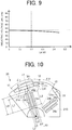
- Fig. 9 is a diagram showing the relationship between the ratio L4/W1 of the width L4 of the opening 21c to the width W1 of the permanent magnet 22 and inductive voltage occurring during the rotation of the rotor 2.
- the inductive voltage is proportional to the magnitude of the magnetic force of the permanent magnet 22.
- Fig. 9 shows the relationship (tendency) of the ratio L4/W1 and the magnitude of the magnetic force of the permanent magnet 22.
- the inductive voltage decreases with the increase in the ratio L4/W1 (i.e., with the increase in the width L4 relative to the width W1).
- the permeance of the permanent magnet 22 decreases and the magnetic force of the permanent magnet 22 decreases.
- the inductive voltage decreases significantly when the ratio L4/W1 exceeds 0.2.
- the magnetic force of the permanent magnet 22 can be maintained more sufficiently as the ratio L4/W1 is closer to zero. Therefore, it is desirable to form the projecting part 21d in an arc-like shape.
- the rotor 2 satisfies 0 ⁇ L4/W1 ⁇ 0.2 in the first region R1. With this configuration, the decrease in the magnetic force of the permanent magnet 22 can be prevented.
- the electric motor 1 according to the first embodiment includes the rotor 2, and thus the electric motor 1 has the advantages described above.
- Fig. 10 is an enlarged view schematically showing a structure of a part of a rotor 20 of an electric motor according to a modification.
- the part of the rotor 20 shown in Fig. 10 corresponds to the part of the rotor 2 shown in Fig. 5 .
- the structure of a rotor core 210 differs from that in the first embodiment. Specifically, in each first region R1, the rotor core 210 has a plurality of openings (specifically, openings 24a, 24b and 24c). The rest of the structure in the rotor 20 is the same as that in the rotor 2.
- each first region R1 a plurality of openings, specifically, the opening 24a (first opening), the opening 24b (second opening) and the opening 24c (third opening) are formed in the rotor core 210.
- the openings 24a, 24b and 24c are formed inside the magnet insertion hole 21a in the radial direction.
- each first region R1 is a region including a magnet insertion hole 21a and a plurality of openings (specifically, the openings 24a, 24b and 24c).
- the opening 24a is formed in parallel with the magnetic pole center c1 on the xy plane. In other words, the opening 24a extends in the radial direction.
- the openings 24b and 24c are adjacent to the opening 24a.
- the openings 24a, 24b and 24c are in parallel with each other.
- a width L6 (maximum width) of the opening 24a in the radial direction differs from a width L7 (maximum width) of the opening 24b in the radial direction and a width L8 (maximum width) of the opening 24c in the radial direction.
- the width L6 is greater than the widths L7 and L8. That is, in the first region R1, the width L6 is the greatest among the widths in the radial direction.
- the width L7 of the opening 24b and the width L8 of the opening 24c are the same as each other. However, the width L7 of the opening 24b and the width L8 of the opening 24c may also be set to differ from each other.
- a width L5 (maximum width) of the opening 24a in the direction perpendicular to the radial direction differs from a width L9 (maximum width) of the opening 24b in the direction perpendicular to the radial direction and a width L10 (maximum width) of the opening 24c in the direction perpendicular to the radial direction.
- the width L5 is greater than the widths L9 and L10. That is, in the first region R1, the width L5 is the greatest among the widths in the direction perpendicular to the radial direction.
- the width L9 of the opening 24b and the width L10 of the opening 24c are the same as each other. However, the width L9 of the opening 24b and the width L10 of the opening 24c may also be set to differ from each other.
- the width L6 is greater than the widths L5, L9 and L10.
- the width L7 is greater than the widths L5, L9 and L10.
- the shortest distance L11 from the opening 24a to the magnet insertion hole 21a and the shortest distance L12 from the opening 24b to the magnet insertion hole 21a differ from each other. Specifically, the shortest distance L11 is shorter than the shortest distance L12. In the example shown in Fig. 10 , the shortest distance L12 from the opening 24b to the magnet insertion hole 21a and the shortest distance from the opening 24c to the magnet insertion hole 21a are the same as each other. Thus, the shortest distance L11 is the shortest among the distances from the openings 24a, 24b and 24c to the magnet insertion hole 21a.
- the shortest distance L12 from the opening 24b to the magnet insertion hole 21a and the shortest distance from the opening 24c to the magnet insertion hole 21a may also be set to differ from each other.
- the shortest distances L11 and L12 are desired to be greater than the thickness of the electromagnetic steel sheet used for forming the rotor core 210, for example.
- the relationship between the sum S1 of the maximum widths of the plurality of openings (openings 24a, 24b and 24c in Fig. 10 ) in the direction perpendicular to the radial direction and the width T1 of the magnet insertion hole 21a satisfy 1.5 ⁇ S1/T1.
- the sum S1 of the maximum widths is the sum of the maximum width of the opening 24a in the direction perpendicular to the radial direction (the width L5 in Fig. 10 ), the maximum width of the opening 24b in the direction perpendicular to the radial direction (the width L9 in Fig. 10 ), and the maximum width of the opening 24c in the direction perpendicular to the radial direction (the width L10 in Fig. 10 ).
- each first region R1 has only one opening 21c
- the shaft 23 is fixed in the rotary shaft insertion hole 21b by injecting resin into the rotary shaft insertion hole 21b
- the resin flows also into the opening 21c.
- the structure of the rotor 2 becomes imbalanced when the opening 21c is not uniformly filled in with the resin.
- the noise of the electric motor 1 is not reduced sufficiently.
- a plurality of openings are formed in each first region R1. Accordingly, when the openings 24a, 24b and 24c are formed in the rotor core 210, the adjustment of the volume of the openings in the first region R1 becomes easy.
- the openings 24a, 24b and 24c can be uniformly filled in with the resin. Accordingly, appropriate balance of the structure of the rotor 20 can be obtained and the same advantages as those described in the first embodiment (e.g., decrease in the noise of the electric motor 1) can be obtained.
- the shortest distance L11 is shorter than the shortest distance L12. Namely, the shortest distance L11 is the shortest among the distances from the openings 24a, 24b and 24c to the magnet insertion hole 21a. Therefore, the overall shape of the plurality of openings (specifically, the openings 24a, 24b and 24c) in the first region R1 is formed so that a central part in the direction perpendicular to the radial direction projects outward in the radial direction similarly to the opening 21c described in the first embodiment. With this configuration, the magnetic flux flowing from the stator 3 into the second region R2 can be prevented from passing through the first region R1. Consequently, the decrease in the magnetic force of the permanent magnet 22 can be prevented and the noise in the electric motor including the rotor 20 can be reduced.
- the relationship between the ratio S1/T1 and the exciting force of the rotor 2 in the radial direction is the same as the relationship (tendency) shown in Fig. 8 . Namely, when the rotor 20 satisfies 1.5 ⁇ S1/T1, the decrease in the exciting force of the rotor 20 is saturated similarly to the first embodiment. Thus, the noise of the electric motor 1 can be reduced when the rotor 20 satisfies 1.5 ⁇ S1/T1. Further, the rotor 20 is desired to satisfy 1.5 ⁇ S1/T1 ⁇ 7.5. With this configuration, the noise of the electric motor according to the modification can be reduced while sufficient rigidity of the rotor core 210 is maintained.
- the electric motor according to the modification includes the rotor 20, and thus the electric motor according to the modification has the advantages described above.
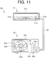
- Fig. 11 is a diagram schematically showing a configuration of the air conditioner 50 according to the second embodiment of the present invention.
- the air conditioner 50 (e.g., refrigeration air conditioner) according to the second embodiment includes an indoor unit 51 as a blower (first blower), refrigerant piping 52, and an outdoor unit 53 as a blower (second blower) connected to the indoor unit 51 by the refrigerant piping 52.
- the indoor unit 51 includes an electric motor 51a (e.g., the electric motor 1 according to the first embodiment), a blower unit 51b that is driven by the electric motor 51a and thereby blows out air, and a housing 51c that covers the electric motor 51a and the blower unit 51b.
- the blower unit 51b includes, for example, a blade 51d driven by the electric motor 51a.
- the blade 51d is fixed to a shaft of the electric motor 51a (e.g., the shaft 23) and generates an air current.
- the outdoor unit 53 includes an electric motor 53a (e.g., the electric motor 1 according to the first embodiment), a blower unit 53b, a compressor 54, and a heat exchanger (not shown).
- the blower unit 53b is driven by the electric motor 53a and thereby blows out air.
- the blower unit 53b includes, for example, a blade 53d driven by the electric motor 53a.
- the blade 53d is fixed to a shaft of the electric motor 53a (e.g., the shaft 23) and generates an air current.
- the compressor 54 includes an electric motor 54a (e.g., the electric motor 1 according to the first embodiment), a compression mechanism 54b (e.g., refrigerant circuit) driven by the electric motor 54a, and a housing 54c that covers the electric motor 54a and the compression mechanism 54b.
- an electric motor 54a e.g., the electric motor 1 according to the first embodiment
- a compression mechanism 54b e.g., refrigerant circuit driven by the electric motor 54a
- a housing 54c that covers the electric motor 54a and the compression mechanism 54b.
- At least one of the indoor unit 51 or the outdoor unit 53 includes the electric motor 1 described in the first embodiment (including the modification).
- the electric motor 1 described in the first embodiment is employed for at least one of the electric motor 51a or the electric motor 53a as a drive source for the blower unit.
- the electric motor 1 described in the first embodiment is also possible to employ the electric motor 1 described in the first embodiment (including the modification) as the electric motor 54a of the compressor 54.
- the air conditioner 50 is capable of performing a cooling operation of blowing out cool air from the indoor unit 51, a heating operation of blowing out warm air, or the like, for example.
- the electric motor 51a is a drive source for driving the blower unit 51b.
- the blower unit 51b is capable of blowing out conditioned air.
- the same advantages as those described in the first embodiment can be obtained since the electric motor 1 described in the first embodiment (including the modification) is employed for at least one of the electric motor 51a or the electric motor 53a. Accordingly, noise of the air conditioner 50 can be reduced.
- a blower including the electric motor 1 according to the first embodiment and a blade (e.g., the blade 51d or 53d) driven by the electric motor 1 can be used independently as a device for blowing out air. This blower can be employed also for equipment other than the air conditioner 50.
- the electric motor 1 according to the first embodiment (including the modification) as the drive source of the compressor 54, the same advantages as those described in the first embodiment can be obtained. Accordingly, noise of the compressor 54 can be reduced.
- the electric motor 1 described in the first embodiment can be mounted not only on the air conditioner 50 but also on equipment having a drive source, such as a ventilating fan, a household electrical appliance and a machine tool.
- 1, 51a, 54a electric motor, 2: rotor, 3: stator, 21: rotor core, 21a: magnet insertion hole, 21b: rotary shaft insertion hole, 21c: opening, 21d: projecting part, 22: permanent magnet, 23: shaft, 31: stator core, 32: coil, 33: insulator, 50: air conditioner, 51: indoor unit, 51d, 53d: blade, 52: refrigerant piping, 53: outdoor unit, 54: compressor, 54b: compression mechanism.
Landscapes
- Engineering & Computer Science (AREA)
- Power Engineering (AREA)
- Mechanical Engineering (AREA)
- General Engineering & Computer Science (AREA)
- Chemical & Material Sciences (AREA)
- Combustion & Propulsion (AREA)
- Physics & Mathematics (AREA)
- Thermal Sciences (AREA)
- Permanent Field Magnets Of Synchronous Machinery (AREA)
- Iron Core Of Rotating Electric Machines (AREA)
- Permanent Magnet Type Synchronous Machine (AREA)
Abstract
Description
- The present invention relates to a rotor used for an electric motor, and in particular, to a consequent-pole type rotor.
- Consequent-pole type rotors are being used as rotors of electric motors. The consequent-pole type rotor is divided into regions each including a permanent magnet and regions including no permanent magnet. For example, a region including a permanent magnet functions as one magnetic pole (e.g., a magnetic pole functioning as a north pole for a stator), and a region between permanent magnets adjacent to each other in a circumferential direction functions as the other magnetic pole (e.g., a pseudo-magnetic pole functioning as a south pole for the stator) (see
Patent Reference 1, for example). - Patent Reference 1: Japanese Patent Application Publication No.
8-182267 - However, in the conventional technology, magnetic flux flowing from the stator to a pseudo-magnetic pole of the consequent-pole type rotor is prone to pass through an adjacent and different magnetic pole in the circumferential direction. Accordingly, a problem arises in that noise in the motor increases.
- An object of the present invention is to reduce the noise in an electric motor.
- A consequent-pole type rotor according to the present invention is a consequent-pole type rotor including a first magnetic pole and a second magnetic pole, including: a rotor core including a magnet insertion hole and an opening formed inside the magnet insertion hole in a radial direction; and a permanent magnet inserted in the magnet insertion hole and forming the first magnetic pole. The consequent-pole type rotor satisfies L1 < L2, where L1 is a first maximum width of the opening in a direction perpendicular to the radial direction and L2 is a second maximum width of the opening in the radial direction. A distance from the opening to the magnet insertion hole is smallest at a magnetic pole center of the first magnetic pole.
- According to the present invention, noise in an electric motor can be reduced.
-
-
Fig. 1 is a partially sectional view schematically showing a structure of an electric motor according to a first embodiment of the present invention. -
Fig. 2 is a front view schematically showing the structure of the electric motor. -
Fig. 3 is a cross-sectional view schematically showing a structure of a rotor and a stator. -
Fig. 4 is a plan view schematically showing the structure of the rotor. -
Fig. 5 is an enlarged view showing a structure of a part of the rotor shown inFig. 4 . -
Fig. 6 is a diagram showing a flow of magnetic flux flowing from a stator into a rotor in a standard type of permanent magnet synchronous motor as a comparative example. -
Fig. 7 is a diagram showing a flow of magnetic flux flowing from the stator into the rotor in the electric motor according to the first embodiment. -
Fig. 8 is a diagram showing the relationship between a ratio L1/T1 and exciting force of the rotor. -
Fig. 9 is a diagram showing the relationship between a ratio L4/W1 and inductive voltage occurring during the rotation of the rotor. -
Fig. 10 is an enlarged view schematically showing a structure of a part of a rotor of an electric motor according to a modification. -
Fig. 11 is a diagram schematically showing a configuration of an air conditioner according to a second embodiment of the present invention. - An
electric motor 1 according to a first embodiment of the present invention will be described below. - In an xyz orthogonal coordinate system shown in each drawing, a z-axis direction (z-axis) represents a direction parallel to an axis line A1 of a
shaft 23 of the electric motor 1 (hereinafter referred to as an "axial direction"), an x-axis direction (x-axis) represents a direction perpendicular to the z-axis direction (z-axis), and a y-axis direction represents a direction perpendicular to both the z-axis direction and the x-axis direction. -
Fig. 1 is a partially sectional view schematically showing a structure of theelectric motor 1 according to the first embodiment of the present invention. -
Fig. 2 is a front view schematically showing the structure of theelectric motor 1. - The
electric motor 1 includes arotor 2, astator 3, acircuit board 4, amagnetic sensor 5 that detects a rotational position of therotor 2, abracket 6,bearings sensor magnet 8 as a magnet for detecting the position of therotor 2. Theelectric motor 1 is a permanent magnet synchronous motor, for example. - The
circuit board 4 is provided on a side of thestator 3 at one end in the axial direction. Electronic components such as a control circuit and themagnetic sensor 5 are attached to thecircuit board 4. Themagnetic sensor 5 detects the rotational position of therotor 2 by detecting a rotational position of thesensor magnet 8. Thesensor magnet 8 is attached to therotor 2 to face themagnetic sensor 5. Thesensor magnet 8 is disk-shaped, for example. Thesensor magnet 8 rotates together with therotor 2. -
Fig. 3 is a cross-sectional view schematically showing a structure of therotor 2 and thestator 3. The arrow D1 shows a circumferential direction of arotor core 21, therotor 2 and the stator 3 (hereinafter referred to simply as "the circumferential direction"). Namely, the arrow D1 shows a direction along an outer circumference of therotor core 21 and therotor 2. - The
stator 3 includes astator core 31, acoil 32 and aninsulator 33. - The
stator core 31 is formed by, for example, stacking a plurality of electromagnetic steel sheets. The thickness of each electromagnetic steel sheet is 0.2 mm to 0.5 mm, for example. Thestator core 31 is formed in a ring-like shape. - The
coil 32 is formed by, for example, winging a winding (e.g., magnet wire) around tooth parts of thestator core 31 via theinsulator 33. The coil 32 (i.e., winding) is formed of material including copper or aluminum, for example. Thecoil 32 is insulated by theinsulator 33. - The
insulator 33 is formed of resin having an insulating property, such as polybutylene terephthalate (PBT), polyphenylene sulfide (PPS), liquid crystal polymer (LCP) or polyethylene terephthalate (PET). Theinsulator 33 formed of resin is a film having a thickness of 0.035 mm to 0.4 mm, for example. - For example, the
insulator 33 is formed integrally with thestator core 31. However, theinsulator 33 may also be formed separately from thestator core 31. In this case, after theinsulator 33 is formed, the formedinsulator 33 is fit in thestator core 31. - In this embodiment, the
stator core 31, thecoil 32 and theinsulator 33 are covered by thermosetting resin (e.g., bulk molding compound (BMC)) such as unsaturated polyester resin. Thestator core 31, thecoil 32 and theinsulator 33 may be fixed by a cylindrical shell formed of material containing iron, for example. In this case, the cylindrical shell is capable of covering thestator 3 together with therotor 2 by means of shrink fitting. - The
rotor 2 is arranged inside thestator 3 via an air gap. Thebracket 6 is pressed into an opening on a load side of the stator 3 (load side of the electric motor 1). Thebearing 7a into which theshaft 23 has been inserted is fixed on the load side of thestator 3. Similarly, thebearing 7b into which theshaft 23 has been inserted is fixed on an anti-load side of thestator 3. Therotor 2 is supported by thebearings - The
sensor magnet 8 detects the rotational position of therotor 2. Thesensor magnet 8 is fixed to a side of therotor 2 at one end in the axial direction to face themagnetic sensor 5. - The
sensor magnet 8 has been magnetized in the axial direction so that its magnetic flux flows into themagnetic sensor 5. Accordingly, themagnetic sensor 5 can be attached to a side of thestator 3 at one end in the axial direction to face thesensor magnet 8. However, the direction of the magnetic flux from thesensor magnet 8 is not limited to the axial direction. - The number of magnetic poles of the
sensor magnet 8 is the same as the number of magnetic poles of therotor 2. Thesensor magnet 8 is positioned so that the polarity of thesensor magnet 8 coincides with the polarity of therotor 2 in regard to the circumferential direction. - The
magnetic sensor 5 detects the rotational position of therotor 2 by detecting the rotational position of thesensor magnet 8. For example, a Hall IC, an MR (magnetoresistance) element, a GMR (giant magnetoresistance) element, a magneto-impedance element, or the like is used for themagnetic sensor 5. Themagnetic sensor 5 is fixed at a position where magnetic flux emitted from thesensor magnet 8 flows (detection position). - The control circuit attached to the
circuit board 4 controls the rotation of therotor 2 by controlling electric current flowing through thecoil 32 of thestator 3 by using the result of the detection by the magnetic sensor 5 (e.g., magnetic pole switching point as a boundary between a north pole and a south pole of the sensor magnet 8). - The
magnetic sensor 5 detects the positions (phases) of the magnetic poles of thesensor magnet 8 and therotor 2 based on the change in the magnetic field flowing into the magnetic sensor 5 (magnetic field intensity). Specifically, themagnetic sensor 5 determines timing at which the direction of the magnetic field changes in the circumferential direction (rotation direction) of the sensor magnet 8 (specifically, the magnetic pole switching points of the sensor magnet 8) by detecting magnetic flux from a north pole of thesensor magnet 8 and magnetic flux heading towards a south pole of thesensor magnet 8. Since thesensor magnet 8 has north poles and south poles alternately arranged in the circumferential direction, the positions of the magnetic poles in the rotation direction (the rotation angle and the phase of the rotor 2) can be grasped by the periodical detection of the magnetic pole switching points of thesensor magnet 8 by themagnetic sensor 5. -
Fig. 4 is a plan view schematically showing a structure of therotor 2. -
Fig. 5 is an enlarged view showing a structure of a part of therotor 2 shown inFig. 4 . - The
rotor 2 includes therotor core 21 as a main magnet part, at least onepermanent magnet 22, and theshaft 23. The axis of rotation of therotor 2 coincides with the axis line A1. Therotor 2 is a permanent magnet embedded rotor, for example. In this embodiment, therotor 2 is a consequent-pole type rotor. - The
rotor 2 of the consequent-pole type includes a first magnetic pole having a first polarity and a second magnetic pole having a second polarity different from the first polarity. In this embodiment, the first magnetic pole is a north pole and the second magnetic pole is a south pole. - In the
rotor 2, a region including a permanent magnet 22 (a first region R1 which will be described later) functions as one magnetic pole (e.g., a magnetic pole functioning as a north pole for the stator) and a region betweenpermanent magnets 22 adjacent to each other in the circumferential direction (a second region R2 which will be described later) functions as a magnetic pole on the other side (e.g., a pseudo-magnetic pole functioning as a south pole for the stator). - The
rotor core 21 includes at least onemagnet insertion hole 21a, a rotaryshaft insertion hole 21b, and at least oneopening 21c. In this embodiment, therotor core 21 includes a plurality ofmagnet insertion holes 21a, and at least onepermanent magnet 22 is inserted in eachmagnet insertion hole 21a. - In this embodiment, the number of the
permanent magnets 22 is half of the number n of the magnetic poles of the rotor 2 (n is an even number larger than or equal to 4). The number n of the magnetic poles of therotor 2 is the sum total of the number of magnetic poles functioning as north poles for thestator 3 and the number of magnetic poles functioning as south poles for thestator 3. - The
rotor core 21 may include a bridge part as a part (specifically, a thin-wall part) of a thin plate (e.g., electromagnetic steel sheets) formed between themagnet insertion hole 21a and an outer surface (outer edge) of therotor 2. This bridge part inhibits occurrence of leakage flux. - However, the
electric motor 1 may also be an SPM (Surface Permanent Magnet) motor. In this case, nomagnet insertion hole 21a is formed in therotor core 21 and thepermanent magnet 22 is attached to the outer surface of therotor core 21 in regard to a radial direction. - The
rotor core 21 is formed with a plurality of electromagnetic steel sheets. Each electromagnetic steel sheet has a thickness of 0.2 mm to 0.5 mm, for example. The electromagnetic steel sheets are stacked in the axial direction. However, therotor core 21 may also be configured as a resin core formed by mixing soft magnetic material and resin together instead of using a plurality of electromagnetic steel sheets. - A plurality of
magnet insertion holes 21a are formed at even intervals in the circumferential direction of therotor core 21. In this embodiment, fivemagnet insertion holes 21a are formed in therotor core 21. Eachmagnet insertion hole 21a penetrates therotor core 21 in the axial direction. - The rotary
shaft insertion hole 21b is formed in a central part of therotor core 21. The rotaryshaft insertion hole 21b penetrates therotor core 21 in the axial direction. Theshaft 23 is inserted in the rotaryshaft insertion hole 21b. - The
shaft 23 is integrated with therotor core 21 by caulking or by using thermoplastic resin such as PBT. The shape of the thermoplastic resin is adjusted appropriately depending on the purpose of theelectric motor 1. In this case, the thermoplastic resin being non-magnetic material is poured into the rotaryshaft insertion hole 21b. With this configuration, magnetic flux flowing from thestator 3 into the second region R2 can be prevented from flowing into theshaft 23 and advantages of theopening 21c which will be described later can be obtained adequately. - A
permanent magnet 22 is inserted in eachmagnet insertion hole 21a. In themagnet insertion hole 21a, parts around thepermanent magnet 22 are filled in with resin, by which thepermanent magnet 22 is fixed in themagnet insertion hole 21a. However, it is also possible to fix thepermanent magnet 22 by a method other than the fixation method using resin. Thepermanent magnet 22 is, for example, a rare-earth magnet containing neodymium or samarium. Thepermanent magnet 22 may also be ferrite magnet containing iron. The type of thepermanent magnet 22 is not limited to the examples in this embodiment; thepermanent magnet 22 may also be formed of different material. - The
permanent magnet 22 in themagnet insertion hole 21a has been magnetized in the radial direction, and accordingly, magnetic flux from therotor 2 flows into thestator 3. Thepermanent magnet 22 forms a north pole of the rotor 2 (specifically, a north pole functioning for the stator 3). Further, the permanent magnet 22 (specifically, magnetic flux from the permanent magnet 22) forms a south pole as a pseudo-magnetic pole of the rotor 2 (specifically, a south pole functioning for the stator 3) in the second region R2 which will be described later. - The
rotor core 21 is divided into the first regions R1 and the second regions R2. In the example shown inFig. 4 and Fig. 5 , each first region R1 is a region between a straight line e1 (first straight line) and a straight line e2 (second straight line) on a plane perpendicular to the axial direction (hereinafter referred to as an "xy plane"), and each second region R2 is a region between the straight line e2 and a straight line e3 on the xy plane. - The straight lines e1, e2 and e3 are boundary lines between a first region R1 and a second region R2 on the xy plane. In the example shown in
Fig. 5 , the straight lines e1 and e2 define a first region R1 on the xy plane and the straight lines e2 and e3 define a second region R2 on the xy plane. - The first region R1 is a region including a
magnet insertion hole 21a and anopening 21c. Thus, the first region R1 forms a north pole functioning for thestator 3. - The second region R2 is a region adjacent to a first region R1. Namely, the second region R2 is a region including no
magnet insertion hole 21a. The second region R2 forms a south pole functioning for thestator 3. - The
opening 21c is formed inside themagnet insertion hole 21a in the radial direction. To maintain sufficient rigidity of therotor core 21, theopening 21c is desired not to be connected with themagnet insertion hole 21a or the rotaryshaft insertion hole 21b. - In each
opening 21c, a width L1 of theopening 21c is less than a width L2 of theopening 21c. Put another way, the width L2 is greater than the width L1. The width L1 is a maximum width of theopening 21c in a direction perpendicular to the radial direction (first maximum width) . The width L2 is a maximum width of theopening 21c in the radial direction (second maximum width). - In the first region R1, the relationship between the width L1 of the
opening 21c and a width T1 of themagnet insertion hole 21a satisfies 1.5 < L1/T1. Further, therotor 2 is desired to satisfy L1/T1 < 7.5. In this embodiment, the width T1 is the width (maximum width) of themagnet insertion hole 21a in the radial direction, that is, the width on a magnetic pole center c1. - In the
opening 21c, a projectingpart 21d as a part of an outer end part in the radial direction projects outward in the radial direction. The projectingpart 21d of theopening 21c coincides with the magnetic pole center c1 on the xy plane. Therefore, a distance L3 from theopening 21c to themagnet insertion hole 21a is the smallest at the magnetic pole center c1 of the north pole. The distance L3 is the width of a connection part, as a part of therotor core 21 formed between theopening 21c and themagnet insertion hole 21a, in the radial direction. Specifically, the distance L3 is a shortest distance from the projectingpart 21d to themagnet insertion hole 21a. - In the first region R1, the relationship between a width L4 of the
opening 21c and a width W1 of thepermanent magnet 22 satisfies 0 < L4/W1 < 0.2. The width L4 is the width (maximum width) of the outer end part of theopening 21c in the radial direction (specifically, the projectingpart 21d) measured in the direction perpendicular to the radial direction. The width W1 is the width (maximum width) of thepermanent magnet 22 in the direction perpendicular to the radial direction. The width W1 of thepermanent magnet 22 is less than the width of themagnet insertion hole 21a in the direction perpendicular to the radial direction by approximately 0.1 mm to 0.5 mm, for example. The width T1 of thepermanent magnet 22 is less than the width of themagnet insertion hole 21a in the radial direction by approximately 0.1 mm to 0.5 mm, for example. In this case, the width W1 of thepermanent magnet 22 is desired to satisfy W1 > 5 × T1. - As shown in
Fig. 5 , the angle formed by the straight line e1 and the straight line e2 on the xy plane is an angle θ1 (first angle), and the angle formed by the straight line e2 and the straight line e3 on the xy plane is an angle θ2 (second angle). In this case, the rotor 2 (specifically, the rotor core 21) satisfies (θ1 + θ2) × n (n is an integer greater than or equal to 4) / 2 = 360 degrees. Here, n is the total number of the first regions R1 (specifically, the number of the first regions R1 in the rotor core 21) and the second regions R2 (specifically, the number of the second regions R2 in the rotor core 21). - In this embodiment, the total number of the first regions R1 (the number of the first regions R1 is 5) and the second regions R2 (the number of the second regions R2 is 5) is 10.
- Advantages of the
rotor 2 will be described below. -
Fig. 6 is a diagram showing a flow of magnetic flux f flowing from astator 300 into arotor 200 in a standard type of permanent magnet synchronous motor as a comparative example. - As shown in
Fig. 6 , in a consequent-pole type rotor, magnetic flux f flowing into a second magnetic pole (corresponding to the second region R2 in this embodiment) is generally prone to pass through a first magnetic pole (corresponding to the first region R1 in this embodiment). Accordingly, noise tends to increase in an electric motor employing a consequent-pole type rotor. -
Fig. 7 is a diagram showing a flow of magnetic flux flowing from thestator 3 into therotor 2 in theelectric motor 1 according to this embodiment. - In this embodiment, the
rotor 2 satisfies L1 < L2. With this configuration, in therotor 2 as a consequent-pole type rotor, the magnetic flux flowing from thestator 3 into the second region R2 can be prevented from passing through the first region R1. As a result, noise in theelectric motor 1 employing therotor 2 can be reduced. - As described above, by forming the
rotor 2 to satisfy L1 < L2, the increase in the noise can be prevented. Therefore, it is desirable to set the width L2 as great as possible. However, when the distance from theopening 21c to themagnet insertion hole 21a is too short, permeance of thepermanent magnet 22 decreases and magnetic force of thepermanent magnet 22 decreases. Thus, in this embodiment, therotor 2 is formed so that the distance L3 is the smallest at the magnetic pole center c1 of the north pole. With this configuration, the decrease in the permeance of thepermanent magnet 22 can be avoided and the decrease in the magnetic force of thepermanent magnet 22 can be avoided. As a result, the decrease in the efficiency of the electric motor 1 (referred to also as "motor efficiency") can be prevented. - Further, by setting the width L1 as great as possible in the state in which the
rotor 2 satisfies L1 < L2, magnetic resistance of theopening 21c can be increased. Accordingly, the magnetic flux flowing from thestator 3 into the second region R2 can be prevented from passing through the first region R1 and the noise of therotor 2 can be reduced. However, it is desirable to determine the width L1 of theopening 21c in consideration of the width T1 of thepermanent magnet 22. -
Fig. 8 is a diagram showing the relationship between the ratio L1/T1 of the width L1 of theopening 21c to the width T1 of themagnet insertion hole 21a and exciting force of therotor 2 in the radial direction. - As shown in
Fig. 8 , the exciting force decreases with the increase in the ratio L1/T1. The decrease in the exciting force is saturated when the ratio L1/T1 is greater than 1.5. Thus, the noise of theelectric motor 1 can be reduced when therotor 2 satisfies 1.5 < L1/T1. On the other hand, when the width L1 of theopening 21c is greater than the width (maximum width) of themagnet insertion hole 21a in the direction perpendicular to the radial direction, the rigidity of therotor core 21 drops. Therefore, therotor 2 is desired to satisfy 1.5 < L1/T1 < 7.5. With this configuration, the noise of theelectric motor 1 can be reduced while maintaining sufficient rigidity of therotor core 21. -
Fig. 9 is a diagram showing the relationship between the ratio L4/W1 of the width L4 of theopening 21c to the width W1 of thepermanent magnet 22 and inductive voltage occurring during the rotation of therotor 2. The inductive voltage is proportional to the magnitude of the magnetic force of thepermanent magnet 22. Thus,Fig. 9 shows the relationship (tendency) of the ratio L4/W1 and the magnitude of the magnetic force of thepermanent magnet 22. - As shown in
Fig. 9 , the inductive voltage decreases with the increase in the ratio L4/W1 (i.e., with the increase in the width L4 relative to the width W1). Thus, with the increase in the width L4, the permeance of thepermanent magnet 22 decreases and the magnetic force of thepermanent magnet 22 decreases. In this embodiment, the inductive voltage decreases significantly when the ratio L4/W1 exceeds 0.2. - As shown in
Fig. 9 , the magnetic force of thepermanent magnet 22 can be maintained more sufficiently as the ratio L4/W1 is closer to zero. Therefore, it is desirable to form the projectingpart 21d in an arc-like shape. - In this embodiment, the
rotor 2 satisfies 0 < L4/W1 < 0.2 in the first region R1. With this configuration, the decrease in the magnetic force of thepermanent magnet 22 can be prevented. - The
electric motor 1 according to the first embodiment includes therotor 2, and thus theelectric motor 1 has the advantages described above. -
Fig. 10 is an enlarged view schematically showing a structure of a part of arotor 20 of an electric motor according to a modification. The part of therotor 20 shown inFig. 10 corresponds to the part of therotor 2 shown inFig. 5 . - In the
rotor 20, the structure of arotor core 210 differs from that in the first embodiment. Specifically, in each first region R1, therotor core 210 has a plurality of openings (specifically,openings rotor 20 is the same as that in therotor 2. - In the example shown in
Fig. 10 , in each first region R1, a plurality of openings, specifically, theopening 24a (first opening), theopening 24b (second opening) and theopening 24c (third opening) are formed in therotor core 210. In each first region R1, theopenings magnet insertion hole 21a in the radial direction. Thus, each first region R1 is a region including amagnet insertion hole 21a and a plurality of openings (specifically, theopenings - The
opening 24a is formed in parallel with the magnetic pole center c1 on the xy plane. In other words, theopening 24a extends in the radial direction. Theopenings opening 24a. Theopenings - A width L6 (maximum width) of the
opening 24a in the radial direction differs from a width L7 (maximum width) of theopening 24b in the radial direction and a width L8 (maximum width) of theopening 24c in the radial direction. In the example shown inFig. 10 , the width L6 is greater than the widths L7 and L8. That is, in the first region R1, the width L6 is the greatest among the widths in the radial direction. In the example shown inFig. 10 , the width L7 of theopening 24b and the width L8 of theopening 24c are the same as each other. However, the width L7 of theopening 24b and the width L8 of theopening 24c may also be set to differ from each other. - A width L5 (maximum width) of the
opening 24a in the direction perpendicular to the radial direction differs from a width L9 (maximum width) of theopening 24b in the direction perpendicular to the radial direction and a width L10 (maximum width) of theopening 24c in the direction perpendicular to the radial direction. In the example shown inFig. 10 , the width L5 is greater than the widths L9 and L10. That is, in the first region R1, the width L5 is the greatest among the widths in the direction perpendicular to the radial direction. In the example shown inFig. 10 , the width L9 of theopening 24b and the width L10 of theopening 24c are the same as each other. However, the width L9 of theopening 24b and the width L10 of theopening 24c may also be set to differ from each other. - The width L6 is greater than the widths L5, L9 and L10. The width L7 is greater than the widths L5, L9 and L10.
- The shortest distance L11 from the
opening 24a to themagnet insertion hole 21a and the shortest distance L12 from theopening 24b to themagnet insertion hole 21a differ from each other. Specifically, the shortest distance L11 is shorter than the shortest distance L12. In the example shown inFig. 10 , the shortest distance L12 from theopening 24b to themagnet insertion hole 21a and the shortest distance from theopening 24c to themagnet insertion hole 21a are the same as each other. Thus, the shortest distance L11 is the shortest among the distances from theopenings magnet insertion hole 21a. However, the shortest distance L12 from theopening 24b to themagnet insertion hole 21a and the shortest distance from theopening 24c to themagnet insertion hole 21a may also be set to differ from each other. The shortest distances L11 and L12 are desired to be greater than the thickness of the electromagnetic steel sheet used for forming therotor core 210, for example. - The relationship between the sum S1 of the maximum widths of the plurality of openings (
openings Fig. 10 ) in the direction perpendicular to the radial direction and the width T1 of themagnet insertion hole 21a satisfy 1.5 < S1/T1. The sum S1 of the maximum widths is the sum of the maximum width of theopening 24a in the direction perpendicular to the radial direction (the width L5 inFig. 10 ), the maximum width of theopening 24b in the direction perpendicular to the radial direction (the width L9 inFig. 10 ), and the maximum width of theopening 24c in the direction perpendicular to the radial direction (the width L10 inFig. 10 ). - Advantages of the
rotor 20 of the electric motor according to the modification will be described below. - In a consequent-pole type rotor, when the
opening 21c is formed in therotor core 21 as shown inFig. 4 and Fig. 5 , for example, the magnetic flux flowing from thestator 3 into the second region R2 can be prevented from passing through the first region R1. As a result, the noise in therotor 2 can be reduced. - However, in the case where each first region R1 has only one
opening 21c, it is not easy to adjust the volume of theopening 21c. For example, when theshaft 23 is fixed in the rotaryshaft insertion hole 21b by injecting resin into the rotaryshaft insertion hole 21b, there are cases where the resin flows also into theopening 21c. In such cases, the structure of therotor 2 becomes imbalanced when theopening 21c is not uniformly filled in with the resin. As a result, there are cases where the noise of theelectric motor 1 is not reduced sufficiently. - In this modification, a plurality of openings (i.e.,
openings openings rotor core 210, the adjustment of the volume of the openings in the first region R1 becomes easy. Thus, when theshaft 23 is fixed in the rotaryshaft insertion hole 21b by injecting resin into the rotaryshaft insertion hole 21b, for example, theopenings rotor 20 can be obtained and the same advantages as those described in the first embodiment (e.g., decrease in the noise of the electric motor 1) can be obtained. - In the
rotor 20, the shortest distance L11 is shorter than the shortest distance L12. Namely, the shortest distance L11 is the shortest among the distances from theopenings magnet insertion hole 21a. Therefore, the overall shape of the plurality of openings (specifically, theopenings opening 21c described in the first embodiment. With this configuration, the magnetic flux flowing from thestator 3 into the second region R2 can be prevented from passing through the first region R1. Consequently, the decrease in the magnetic force of thepermanent magnet 22 can be prevented and the noise in the electric motor including therotor 20 can be reduced. - The relationship between the ratio S1/T1 and the exciting force of the
rotor 2 in the radial direction is the same as the relationship (tendency) shown inFig. 8 . Namely, when therotor 20 satisfies 1.5 < S1/T1, the decrease in the exciting force of therotor 20 is saturated similarly to the first embodiment. Thus, the noise of theelectric motor 1 can be reduced when therotor 20 satisfies 1.5 < S1/T1. Further, therotor 20 is desired to satisfy 1.5 < S1/T1 < 7.5. With this configuration, the noise of the electric motor according to the modification can be reduced while sufficient rigidity of therotor core 210 is maintained. - The electric motor according to the modification includes the
rotor 20, and thus the electric motor according to the modification has the advantages described above. - An
air conditioner 50 according to a second embodiment of the present invention will be described below. -
Fig. 11 is a diagram schematically showing a configuration of theair conditioner 50 according to the second embodiment of the present invention. - The air conditioner 50 (e.g., refrigeration air conditioner) according to the second embodiment includes an
indoor unit 51 as a blower (first blower),refrigerant piping 52, and anoutdoor unit 53 as a blower (second blower) connected to theindoor unit 51 by therefrigerant piping 52. - The
indoor unit 51 includes anelectric motor 51a (e.g., theelectric motor 1 according to the first embodiment), ablower unit 51b that is driven by theelectric motor 51a and thereby blows out air, and ahousing 51c that covers theelectric motor 51a and theblower unit 51b. Theblower unit 51b includes, for example, ablade 51d driven by theelectric motor 51a. For example, theblade 51d is fixed to a shaft of theelectric motor 51a (e.g., the shaft 23) and generates an air current. - The
outdoor unit 53 includes anelectric motor 53a (e.g., theelectric motor 1 according to the first embodiment), ablower unit 53b, acompressor 54, and a heat exchanger (not shown). Theblower unit 53b is driven by theelectric motor 53a and thereby blows out air. Theblower unit 53b includes, for example, ablade 53d driven by theelectric motor 53a. For example, theblade 53d is fixed to a shaft of theelectric motor 53a (e.g., the shaft 23) and generates an air current. Thecompressor 54 includes anelectric motor 54a (e.g., theelectric motor 1 according to the first embodiment), acompression mechanism 54b (e.g., refrigerant circuit) driven by theelectric motor 54a, and ahousing 54c that covers theelectric motor 54a and thecompression mechanism 54b. - In the
air conditioner 50, at least one of theindoor unit 51 or theoutdoor unit 53 includes theelectric motor 1 described in the first embodiment (including the modification). Specifically, theelectric motor 1 described in the first embodiment is employed for at least one of theelectric motor 51a or theelectric motor 53a as a drive source for the blower unit. Further, it is also possible to employ theelectric motor 1 described in the first embodiment (including the modification) as theelectric motor 54a of thecompressor 54. - The
air conditioner 50 is capable of performing a cooling operation of blowing out cool air from theindoor unit 51, a heating operation of blowing out warm air, or the like, for example. In theindoor unit 51, theelectric motor 51a is a drive source for driving theblower unit 51b. Theblower unit 51b is capable of blowing out conditioned air. - With the
air conditioner 50 according to the second embodiment, the same advantages as those described in the first embodiment can be obtained since theelectric motor 1 described in the first embodiment (including the modification) is employed for at least one of theelectric motor 51a or theelectric motor 53a. Accordingly, noise of theair conditioner 50 can be reduced. - Further, by using the
electric motor 1 according to the first embodiment (including the modification) as the drive source of a blower (e.g., the indoor unit 51), the same advantages as those described in the first embodiment can be obtained. Accordingly, noise of the blower can be reduced. A blower including theelectric motor 1 according to the first embodiment and a blade (e.g., theblade electric motor 1 can be used independently as a device for blowing out air. This blower can be employed also for equipment other than theair conditioner 50. - Furthermore, by using the
electric motor 1 according to the first embodiment (including the modification) as the drive source of thecompressor 54, the same advantages as those described in the first embodiment can be obtained. Accordingly, noise of thecompressor 54 can be reduced. - The
electric motor 1 described in the first embodiment can be mounted not only on theair conditioner 50 but also on equipment having a drive source, such as a ventilating fan, a household electrical appliance and a machine tool. - Features in the embodiments (including the modification) described above can be appropriately combined with each other.
- 1, 51a, 54a: electric motor, 2: rotor, 3: stator, 21: rotor core, 21a: magnet insertion hole, 21b: rotary shaft insertion hole, 21c: opening, 21d: projecting part, 22: permanent magnet, 23: shaft, 31: stator core, 32: coil, 33: insulator, 50: air conditioner, 51: indoor unit, 51d, 53d: blade, 52: refrigerant piping, 53: outdoor unit, 54: compressor, 54b: compression mechanism.
Claims (17)
- A consequent-pole type rotor including a first magnetic pole and a second magnetic pole, comprising:a rotor core including a magnet insertion hole and an opening formed inside the magnet insertion hole in a radial direction; anda permanent magnet inserted in the magnet insertion hole and forming the first magnetic pole, whereinthe consequent-pole type rotor satisfies L1 < L2, where L1 is a first maximum width of the opening in a direction perpendicular to the radial direction and L2 is a second maximum width of the opening in the radial direction, anda distance from the opening to the magnet insertion hole is smallest at a magnetic pole center of the first magnetic pole.
- The consequent-pole type rotor according to claim 1, wherein the consequent-pole type rotor satisfies 1.5 < L1/T1, where L1 is the first maximum width and T1 is a width of the magnet insertion hole in the radial direction.
- The consequent-pole type rotor according to claim 2, wherein the consequent-pole type rotor satisfies L1/T1 < 7.5.
- The consequent-pole type rotor according to any one of claims 1 to 3, wherein the consequent-pole type rotor satisfies 0 < L4/W1 < 0.2, where
L4 is a width of an outer end part of the opening in the radial direction, L4 being the width measured in the direction perpendicular to the radial direction, and
W1 is a width of the permanent magnet in the direction perpendicular to the radial direction. - A consequent-pole type rotor including a first magnetic pole and a second magnetic pole, comprising:a rotor core including a magnet insertion hole and a plurality of openings formed inside the magnet insertion hole in a radial direction; anda permanent magnet inserted in the magnet insertion hole, whereinthe rotor core is divided into a first region and a second region adjacent to the first region, the first region including the magnet insertion hole and the plurality of openings and forming the first magnetic pole, the second region forming the second magnetic pole,the plurality of openings are formed in the first region, andthe consequent-pole type rotor satisfies (θ1 + θ2) × n/2 = 360 degrees, wherea first straight line and a second straight line are two straight lines defining the first region on a plane perpendicular to an axial direction,the second straight line and a third straight line are two straight lines defining the second region on the plane,θ1 is an angle formed by the first straight line and the second straight line on the plane,θ2 is an angle formed by the second straight line and the third straight line on the plane, andn (n is an even number greater than or equal to 4) is a total number of the first and second regions, whereina shortest distance from a first opening of the plurality of openings to the magnet insertion hole and a shortest distance from a second opening of the plurality of openings to the magnet insertion hole are different from each other, anda maximum width of the first opening in the radial direction is greater than a maximum width of the first opening in a direction perpendicular to the radial direction.
- The consequent-pole type rotor according to claim 5, wherein the maximum width of the first opening in the radial direction is greater than a maximum width of the second opening in the direction perpendicular to the radial direction.
- The consequent-pole type rotor according to claim 5 or 6, wherein the maximum width of the first opening in the radial direction is greater than a maximum width of the second opening in the radial direction.
- The consequent-pole type rotor according to any one of claims 5 to 7, wherein the consequent-pole type rotor satisfies 1.5 < S1/T1, where S1 is a sum of maximum widths of the plurality of openings in the direction perpendicular to the radial direction and T1 is a width of the magnet insertion hole in the radial direction.
- The consequent-pole type rotor according to claim 8, wherein the consequent-pole type rotor satisfies S1/T1 < 7.5.
- An electric motor comprising:a stator; anda consequent-pole type rotor including a first magnetic pole and a second magnetic pole, whereinthe consequent-pole type rotor includes:a rotor core including a magnet insertion hole and an opening formed inside the magnet insertion hole in a radial direction; anda permanent magnet inserted in the magnet insertion hole and forming the first magnetic pole, whereinthe consequent-pole type rotor satisfies L1 < L2, where L1 is a first maximum width of the opening in a direction perpendicular to the radial direction and L2 is a second maximum width of the opening in the radial direction, anda distance from the opening to the magnet insertion hole is smallest at a magnetic pole center of the first magnetic pole.
- An electric motor comprising:a stator; anda consequent-pole type rotor including a first magnetic pole and a second magnetic pole, whereinthe consequent-pole type rotor includes:a rotor core including a magnet insertion hole and a plurality of openings formed inside the magnet insertion hole in a radial direction; anda permanent magnet inserted in the magnet insertion hole, whereinthe rotor core is divided into a first region and a second region adjacent to the first region, the first region including the magnet insertion hole and the plurality of openings and forming the first magnetic pole, the second region forming the second magnetic pole,the plurality of openings are formed in the first region, andthe consequent-pole type rotor satisfies (θ1 + θ2) × n/2 = 360 degrees, wherea first straight line and a second straight line are two straight lines defining the first region on a plane perpendicular to an axial direction,the second straight line and a third straight line are two straight lines defining the second region on the plane,θ1 is an angle formed by the first straight line and the second straight line on the plane,θ2 is an angle formed by the second straight line and the third straight line on the plane, andn (n is an even number greater than or equal to 4) is a total number of the first and second regions, whereina shortest distance from a first opening of the plurality of openings to the magnet insertion hole and a shortest distance from a second opening of the plurality of openings to the magnet insertion hole are different from each other, anda maximum width of the first opening in the radial direction is greater than a maximum width of the first opening in a direction perpendicular to the radial direction.
- A compressor comprising:an electric motor; anda compression mechanism driven by the electric motor, whereinthe electric motor includes:a stator; anda consequent-pole type rotor including a first magnetic pole and a second magnetic pole, andthe consequent-pole type rotor includes:a rotor core including a magnet insertion hole and an opening formed inside the magnet insertion hole in a radial direction; anda permanent magnet inserted in the magnet insertion hole and forming the first magnetic pole, whereinthe consequent-pole type rotor satisfies L1 < L2, where L1 is a first maximum width of the opening in a direction perpendicular to the radial direction and L2 is a second maximum width of the opening in the radial direction, anda distance from the opening to the magnet insertion hole is smallest at a magnetic pole center of the first magnetic pole.
- A compressor comprising:an electric motor; anda compression mechanism driven by the electric motor, whereinthe electric motor includes:a stator; anda consequent-pole type rotor including a first magnetic pole and a second magnetic pole, andthe consequent-pole type rotor includes:a rotor core including a magnet insertion hole and a plurality of openings formed inside the magnet insertion hole in a radial direction; anda permanent magnet inserted in the magnet insertion hole, whereinthe rotor core is divided into a first region and a second region adjacent to the first region, the first region including the magnet insertion hole and the plurality of openings and forming the first magnetic pole, the second region forming the second magnetic pole,the plurality of openings are formed in the first region, andthe consequent-pole type rotor satisfies (θ1 + θ2) × n/2 = 360 degrees, wherea first straight line and a second straight line are two straight lines defining the first region on a plane perpendicular to an axial direction,the second straight line and a third straight line are two straight lines defining the second region on the plane,θ1 is an angle formed by the first straight line and the second straight line on the plane,θ2 is an angle formed by the second straight line and the third straight line on the plane, andn (n is an even number greater than or equal to 4) is a total number of the first and second regions, whereina shortest distance from a first opening of the plurality of openings to the magnet insertion hole and a shortest distance from a second opening of the plurality of openings to the magnet insertion hole are different from each other, anda maximum width of the first opening in the radial direction is greater than a maximum width of the first opening in a direction perpendicular to the radial direction.
- A blower comprising:an electric motor; anda blade driven by the electric motor, whereinthe electric motor includes:a stator; anda consequent-pole type rotor including a first magnetic pole and a second magnetic pole, andthe consequent-pole type rotor includes:a rotor core including a magnet insertion hole and an opening formed inside the magnet insertion hole in a radial direction; anda permanent magnet inserted in the magnet insertion hole and forming the first magnetic pole, whereinthe consequent-pole type rotor satisfies L1 < L2, where L1 is a first maximum width of the opening in a direction perpendicular to the radial direction and L2 is a second maximum width of the opening in the radial direction, anda distance from the opening to the magnet insertion hole is smallest at a magnetic pole center of the first magnetic pole.
- A blower comprising:an electric motor; anda blade driven by the electric motor, whereinthe electric motor includes:a stator; anda consequent-pole type rotor including a first magnetic pole and a second magnetic pole, andthe consequent-pole type rotor includes:a rotor core including a magnet insertion hole and a plurality of openings formed inside the magnet insertion hole in a radial direction; anda permanent magnet inserted in the magnet insertion hole, whereinthe rotor core is divided into a first region and a second region adjacent to the first region, the first region including the magnet insertion hole and the plurality of openings and forming the first magnetic pole, the second region forming the second magnetic pole,the plurality of openings are formed in the first region, andthe consequent-pole type rotor satisfies (θ1 + θ2) × n/2 = 360 degrees, wherea first straight line and a second straight line are two straight lines defining the first region on a plane perpendicular to an axial direction,the second straight line and a third straight line are two straight lines defining the second region on the plane,θ1 is an angle formed by the first straight line and the second straight line on the plane,θ2 is an angle formed by the second straight line and the third straight line on the plane, andn (n is an even number greater than or equal to 4) is a total number of the first and second regions, whereina shortest distance from a first opening of the plurality of openings to the magnet insertion hole and a shortest distance from a second opening of the plurality of openings to the magnet insertion hole are different from each other, anda maximum width of the first opening in the radial direction is greater than a maximum width of the first opening in a direction perpendicular to the radial direction.
- An air conditioner comprising:an indoor unit; andan outdoor unit connected to the indoor unit, whereinat least one of the indoor unit or the outdoor unit includes an electric motor,the electric motor includes:a stator; anda consequent-pole type rotor including a first magnetic pole and a second magnetic pole, andthe consequent-pole type rotor includes:a rotor core including a magnet insertion hole and an opening formed inside the magnet insertion hole in a radial direction; anda permanent magnet inserted in the magnet insertion hole and forming the first magnetic pole, whereinthe consequent-pole type rotor satisfies L1 < L2, where L1 is a first maximum width of the opening in a direction perpendicular to the radial direction and L2 is a second maximum width of the opening in the radial direction, anda distance from the opening to the magnet insertion hole is smallest at a magnetic pole center of the first magnetic pole.
- An air conditioner comprising:an indoor unit; andan outdoor unit connected to the indoor unit, whereinat least one of the indoor unit or the outdoor unit includes an electric motor,the electric motor includes:a stator; anda consequent-pole type rotor including a first magnetic pole and a second magnetic pole, andthe consequent-pole type rotor includes:a rotor core including a magnet insertion hole and a plurality of openings formed inside the magnet insertion hole in a radial direction; anda permanent magnet inserted in the magnet insertion hole, whereinthe rotor core is divided into a first region and a second region adjacent to the first region, the first region including the magnet insertion hole and the plurality of openings and forming the first magnetic pole, the second region forming the second magnetic pole,the plurality of openings are formed in the first region, andthe consequent-pole type rotor satisfies (θ1 + θ2) × n/2 = 360 degrees, wherea first straight line and a second straight line are two straight lines defining the first region on a plane perpendicular to an axial direction,the second straight line and a third straight line are two straight lines defining the second region on the plane,θ1 is an angle formed by the first straight line and the second straight line on the plane,θ2 is an angle formed by the second straight line and the third straight line on the plane, andn (n is an even number greater than or equal to 4) is a total number of the first and second regions, whereina shortest distance from a first opening of the plurality of openings to the magnet insertion hole and a shortest distance from a second opening of the plurality of openings to the magnet insertion hole are different from each other, anda maximum width of the first opening in the radial direction is greater than a maximum width of the first opening in a direction perpendicular to the radial direction.
Applications Claiming Priority (1)
| Application Number | Priority Date | Filing Date | Title |
|---|---|---|---|
| PCT/JP2017/031932 WO2019049203A1 (en) | 2017-09-05 | 2017-09-05 | Consequent pole-type motor, electric motor, compressor, air blower, and air conditioner |
Publications (3)
| Publication Number | Publication Date |
|---|---|
| EP3681014A1 true EP3681014A1 (en) | 2020-07-15 |
| EP3681014A4 EP3681014A4 (en) | 2020-08-26 |
| EP3681014B1 EP3681014B1 (en) | 2024-04-03 |
Family
ID=65633803
Family Applications (1)
| Application Number | Title | Priority Date | Filing Date |
|---|---|---|---|
| EP17924439.7A Active EP3681014B1 (en) | 2017-09-05 | 2017-09-05 | Consequent pole-type motor, electric motor, compressor, air blower, and air conditioner |
Country Status (8)
| Country | Link |
|---|---|
| US (1) | US11342802B2 (en) |
| EP (1) | EP3681014B1 (en) |
| JP (1) | JP6873250B2 (en) |
| KR (1) | KR102359392B1 (en) |
| CN (1) | CN111033948B (en) |
| AU (1) | AU2017431234B2 (en) |
| ES (1) | ES2978013T3 (en) |
| WO (1) | WO2019049203A1 (en) |
Families Citing this family (20)
| Publication number | Priority date | Publication date | Assignee | Title |
|---|---|---|---|---|
| WO2018179025A1 (en) * | 2017-03-27 | 2018-10-04 | 三菱電機株式会社 | Electric motor and air conditioning device |
| CN111511874A (en) | 2017-12-18 | 2020-08-07 | 大金工业株式会社 | Refrigeration cycle device |
| US11435118B2 (en) | 2017-12-18 | 2022-09-06 | Daikin Industries, Ltd. | Heat source unit and refrigeration cycle apparatus |
| US11441802B2 (en) | 2017-12-18 | 2022-09-13 | Daikin Industries, Ltd. | Air conditioning apparatus |
| US12270575B2 (en) | 2017-12-18 | 2025-04-08 | Daikin Industries, Ltd. | Warm-water generating apparatus |
| US11906207B2 (en) | 2017-12-18 | 2024-02-20 | Daikin Industries, Ltd. | Refrigeration apparatus |
| US11549695B2 (en) | 2017-12-18 | 2023-01-10 | Daikin Industries, Ltd. | Heat exchange unit |
| US11441819B2 (en) | 2017-12-18 | 2022-09-13 | Daikin Industries, Ltd. | Refrigeration cycle apparatus |
| US11493244B2 (en) | 2017-12-18 | 2022-11-08 | Daikin Industries, Ltd. | Air-conditioning unit |
| US11506425B2 (en) | 2017-12-18 | 2022-11-22 | Daikin Industries, Ltd. | Refrigeration cycle apparatus |
| US11365335B2 (en) | 2017-12-18 | 2022-06-21 | Daikin Industries, Ltd. | Composition comprising refrigerant, use thereof, refrigerating machine having same, and method for operating said refrigerating machine |
| US12379140B2 (en) | 2017-12-18 | 2025-08-05 | Daikin Industries., Ltd. | Air conditioner |
| US11549041B2 (en) | 2017-12-18 | 2023-01-10 | Daikin Industries, Ltd. | Composition containing refrigerant, use of said composition, refrigerator having said composition, and method for operating said refrigerator |
| KR20200098565A (en) | 2017-12-18 | 2020-08-20 | 다이킨 고교 가부시키가이샤 | Composition containing a refrigerant, its use, a refrigerator having the same, and a method of operating the refrigerator |
| US11820933B2 (en) | 2017-12-18 | 2023-11-21 | Daikin Industries, Ltd. | Refrigeration cycle apparatus |
| JP1665115S (en) * | 2020-02-27 | 2020-08-03 | ||
| JP1665117S (en) * | 2020-02-27 | 2020-08-03 | ||
| KR102902021B1 (en) | 2020-10-20 | 2025-12-18 | 삼성전자주식회사 | Consequent pole type interior permanent magnet synchronous motor |
| IT202000028565A1 (en) * | 2020-11-26 | 2022-05-26 | I M E Ind Motori Elettrici S P A | FAN ASSEMBLY |
| KR102497574B1 (en) | 2020-12-31 | 2023-02-07 | 한양대학교 에리카산학협력단 | Permanent Magnet Synchronous Machine |
Family Cites Families (25)
| Publication number | Priority date | Publication date | Assignee | Title |
|---|---|---|---|---|
| US4038061A (en) * | 1975-12-29 | 1977-07-26 | Heil-Quaker Corporation | Air conditioner control |
| JP3424774B2 (en) | 1994-12-22 | 2003-07-07 | 株式会社安川電機 | Permanent magnet type rotor |
| DE59604144D1 (en) | 1995-02-21 | 2000-02-17 | Siemens Ag | Hybrid excited electrical machine |
| EP0729216A3 (en) | 1995-02-21 | 1998-03-11 | Siemens Aktiengesellschaft | Hybride excited synchronous machine |
| JP4527998B2 (en) * | 2004-02-20 | 2010-08-18 | 三菱電機株式会社 | Electric motor, hermetic compressor and fan motor |
| TWI348258B (en) * | 2006-11-10 | 2011-09-01 | Ind Tech Res Inst | A motor mechanism of dc frequency conversion of compressor |
| JP5611656B2 (en) * | 2009-05-29 | 2014-10-22 | アスモ株式会社 | Rotor and motor |
| US8242654B2 (en) * | 2009-05-20 | 2012-08-14 | Asmo Co., Ltd. | Rotor and motor |
| EP2536003B1 (en) * | 2010-02-08 | 2018-01-17 | Mitsubishi Electric Corporation | Rotor of permanent magnet embedded motor, blower, and compressor |
| JP5491298B2 (en) * | 2010-06-30 | 2014-05-14 | アスモ株式会社 | Rotor, motor, and method of manufacturing rotor |
| US9178392B2 (en) * | 2010-08-27 | 2015-11-03 | Mitsubishi Electric Corporation | Rotor of permanent magnet embedded motor, compressor, and refrigeration and air conditioning apparatus |
| JP5731251B2 (en) * | 2011-03-25 | 2015-06-10 | アスモ株式会社 | Rotor and motor |
| JP5918958B2 (en) * | 2011-09-29 | 2016-05-18 | アスモ株式会社 | Manufacturing method of rotor |
| CN103891102B (en) * | 2011-10-24 | 2016-08-24 | 三菱电机株式会社 | Rotor, compressor and the refrigerating air conditioning device of permanent magnet embedded-type electric motivation |
| JP5737267B2 (en) | 2012-10-30 | 2015-06-17 | 株式会社デンソー | Rotor and rotating electric machine using the same |
| WO2014068655A1 (en) * | 2012-10-30 | 2014-05-08 | 三菱電機株式会社 | Electric motor with embedded permanent magnet, and refrigeration and air conditioning equipment equipped with same |
| JP5796569B2 (en) * | 2012-12-28 | 2015-10-21 | 株式会社デンソー | Rotor and rotating electric machine using the same |
| JP6251900B2 (en) * | 2013-03-08 | 2017-12-27 | 株式会社明電舎 | Permanent magnet rotating electric machine |
| WO2015045027A1 (en) * | 2013-09-25 | 2015-04-02 | 三菱電機株式会社 | Embedded permanent magnet type electric motor, compressor, and refrigeration air-conditioning device |
| US10027193B2 (en) * | 2014-04-22 | 2018-07-17 | Mitsubishi Electric Corporation | Embedded permanent magnet-type electric motor, compressor, and refrigeration/air-conditioning device |
| JP2016226218A (en) * | 2015-06-02 | 2016-12-28 | 株式会社豊田自動織機 | Permanent magnet embedded rotor for rotary electric machine |
| WO2017014207A1 (en) | 2015-07-21 | 2017-01-26 | アスモ 株式会社 | Motor |
| US11114909B2 (en) | 2015-07-21 | 2021-09-07 | Denso Corporation | Motor |
| KR102008114B1 (en) | 2015-11-18 | 2019-08-06 | 미쓰비시덴키 가부시키가이샤 | Electric motor and air conditioner |
| CN107124054B (en) * | 2017-06-29 | 2023-04-25 | 珠海格力节能环保制冷技术研究中心有限公司 | Alternating pole permanent magnet motor and rotor thereof |
-
2017
- 2017-09-05 CN CN201780094044.7A patent/CN111033948B/en not_active Expired - Fee Related
- 2017-09-05 US US16/638,795 patent/US11342802B2/en active Active
- 2017-09-05 AU AU2017431234A patent/AU2017431234B2/en not_active Ceased
- 2017-09-05 JP JP2019540154A patent/JP6873250B2/en not_active Expired - Fee Related
- 2017-09-05 EP EP17924439.7A patent/EP3681014B1/en active Active
- 2017-09-05 ES ES17924439T patent/ES2978013T3/en active Active
- 2017-09-05 KR KR1020207004263A patent/KR102359392B1/en not_active Expired - Fee Related
- 2017-09-05 WO PCT/JP2017/031932 patent/WO2019049203A1/en not_active Ceased
Also Published As
| Publication number | Publication date |
|---|---|
| US20210135520A1 (en) | 2021-05-06 |
| KR102359392B1 (en) | 2022-02-08 |
| AU2017431234B2 (en) | 2021-09-09 |
| EP3681014B1 (en) | 2024-04-03 |
| AU2017431234A1 (en) | 2020-03-05 |
| ES2978013T3 (en) | 2024-09-04 |
| WO2019049203A1 (en) | 2019-03-14 |
| CN111033948B (en) | 2022-08-05 |
| US11342802B2 (en) | 2022-05-24 |
| JPWO2019049203A1 (en) | 2020-04-16 |
| CN111033948A (en) | 2020-04-17 |
| JP6873250B2 (en) | 2021-05-19 |
| KR20200030565A (en) | 2020-03-20 |
| EP3681014A4 (en) | 2020-08-26 |
Similar Documents
| Publication | Publication Date | Title |
|---|---|---|
| EP3681014B1 (en) | Consequent pole-type motor, electric motor, compressor, air blower, and air conditioner | |
| EP3817194B1 (en) | Electric motor, blower, and air conditioning device | |
| JP6964672B2 (en) | Rotors, motors, blowers and air conditioners | |
| US11342814B2 (en) | Sensor magnet, motor, and air conditioner | |
| CN109792174B (en) | Motor and air conditioner | |
| JP7098047B2 (en) | Motors, fans, and air conditioners | |
| US12009698B2 (en) | Rotor, electric motor, fan, and air conditioner | |
| US11909259B2 (en) | Stator, motor, fan, air conditioner, and method for manufacturing stator | |
| JPWO2020026403A1 (en) | How to manufacture rotors, motors, fans, air conditioners, and rotors | |
| EP4425753A1 (en) | Rotor, electric motor, fan, and air conditioner | |
| JPWO2020026406A1 (en) | How to manufacture rotors, motors, fans, air conditioners, and rotors |
Legal Events
| Date | Code | Title | Description |
|---|---|---|---|
| STAA | Information on the status of an ep patent application or granted ep patent |
Free format text: STATUS: THE INTERNATIONAL PUBLICATION HAS BEEN MADE |
|
| PUAI | Public reference made under article 153(3) epc to a published international application that has entered the european phase |
Free format text: ORIGINAL CODE: 0009012 |
|
| STAA | Information on the status of an ep patent application or granted ep patent |
Free format text: STATUS: REQUEST FOR EXAMINATION WAS MADE |
|
| 17P | Request for examination filed |
Effective date: 20200227 |
|
| AK | Designated contracting states |
Kind code of ref document: A1 Designated state(s): AL AT BE BG CH CY CZ DE DK EE ES FI FR GB GR HR HU IE IS IT LI LT LU LV MC MK MT NL NO PL PT RO RS SE SI SK SM TR |
|
| AX | Request for extension of the european patent |
Extension state: BA ME |
|
| A4 | Supplementary search report drawn up and despatched |
Effective date: 20200727 |
|
| RIC1 | Information provided on ipc code assigned before grant |
Ipc: H02K 1/27 20060101AFI20200721BHEP Ipc: H02K 1/24 20060101ALI20200721BHEP |
|
| DAV | Request for validation of the european patent (deleted) | ||
| DAX | Request for extension of the european patent (deleted) | ||
| STAA | Information on the status of an ep patent application or granted ep patent |
Free format text: STATUS: EXAMINATION IS IN PROGRESS |
|
| 17Q | First examination report despatched |
Effective date: 20210322 |
|
| REG | Reference to a national code |
Ref country code: DE Ref legal event code: R079 Free format text: PREVIOUS MAIN CLASS: H02K0001270000 Ipc: H02K0001240000 Ref country code: DE Ref legal event code: R079 Ref document number: 602017080733 Country of ref document: DE Free format text: PREVIOUS MAIN CLASS: H02K0001270000 Ipc: H02K0001240000 |
|
| GRAP | Despatch of communication of intention to grant a patent |
Free format text: ORIGINAL CODE: EPIDOSNIGR1 |
|
| STAA | Information on the status of an ep patent application or granted ep patent |
Free format text: STATUS: GRANT OF PATENT IS INTENDED |
|
| RIC1 | Information provided on ipc code assigned before grant |
Ipc: H02K 1/2746 20220101ALI20231110BHEP Ipc: H02K 1/24 20060101AFI20231110BHEP |
|
| INTG | Intention to grant announced |
Effective date: 20231129 |
|
| GRAS | Grant fee paid |
Free format text: ORIGINAL CODE: EPIDOSNIGR3 |
|
| GRAA | (expected) grant |
Free format text: ORIGINAL CODE: 0009210 |
|
| STAA | Information on the status of an ep patent application or granted ep patent |
Free format text: STATUS: THE PATENT HAS BEEN GRANTED |
|
| AK | Designated contracting states |
Kind code of ref document: B1 Designated state(s): AL AT BE BG CH CY CZ DE DK EE ES FI FR GB GR HR HU IE IS IT LI LT LU LV MC MK MT NL NO PL PT RO RS SE SI SK SM TR |
|
| REG | Reference to a national code |
Ref country code: GB Ref legal event code: FG4D |
|
| REG | Reference to a national code |
Ref country code: CH Ref legal event code: EP |
|
| REG | Reference to a national code |
Ref country code: DE Ref legal event code: R096 Ref document number: 602017080733 Country of ref document: DE |
|
| REG | Reference to a national code |
Ref country code: IE Ref legal event code: FG4D |
|
| REG | Reference to a national code |
Ref country code: LT Ref legal event code: MG9D |
|
| REG | Reference to a national code |
Ref country code: NL Ref legal event code: MP Effective date: 20240403 |
|
| REG | Reference to a national code |
Ref country code: ES Ref legal event code: FG2A Ref document number: 2978013 Country of ref document: ES Kind code of ref document: T3 Effective date: 20240904 |
|
| REG | Reference to a national code |
Ref country code: AT Ref legal event code: MK05 Ref document number: 1673477 Country of ref document: AT Kind code of ref document: T Effective date: 20240403 |
|
| PG25 | Lapsed in a contracting state [announced via postgrant information from national office to epo] |
Ref country code: NL Free format text: LAPSE BECAUSE OF FAILURE TO SUBMIT A TRANSLATION OF THE DESCRIPTION OR TO PAY THE FEE WITHIN THE PRESCRIBED TIME-LIMIT Effective date: 20240403 |
|
| PG25 | Lapsed in a contracting state [announced via postgrant information from national office to epo] |
Ref country code: NL Free format text: LAPSE BECAUSE OF FAILURE TO SUBMIT A TRANSLATION OF THE DESCRIPTION OR TO PAY THE FEE WITHIN THE PRESCRIBED TIME-LIMIT Effective date: 20240403 |
|
| PG25 | Lapsed in a contracting state [announced via postgrant information from national office to epo] |
Ref country code: IS Free format text: LAPSE BECAUSE OF FAILURE TO SUBMIT A TRANSLATION OF THE DESCRIPTION OR TO PAY THE FEE WITHIN THE PRESCRIBED TIME-LIMIT Effective date: 20240803 |
|
| PG25 | Lapsed in a contracting state [announced via postgrant information from national office to epo] |
Ref country code: BG Free format text: LAPSE BECAUSE OF FAILURE TO SUBMIT A TRANSLATION OF THE DESCRIPTION OR TO PAY THE FEE WITHIN THE PRESCRIBED TIME-LIMIT Effective date: 20240403 |
|
| PG25 | Lapsed in a contracting state [announced via postgrant information from national office to epo] |
Ref country code: HR Free format text: LAPSE BECAUSE OF FAILURE TO SUBMIT A TRANSLATION OF THE DESCRIPTION OR TO PAY THE FEE WITHIN THE PRESCRIBED TIME-LIMIT Effective date: 20240403 Ref country code: FI Free format text: LAPSE BECAUSE OF FAILURE TO SUBMIT A TRANSLATION OF THE DESCRIPTION OR TO PAY THE FEE WITHIN THE PRESCRIBED TIME-LIMIT Effective date: 20240403 |
|
| PG25 | Lapsed in a contracting state [announced via postgrant information from national office to epo] |
Ref country code: GR Free format text: LAPSE BECAUSE OF FAILURE TO SUBMIT A TRANSLATION OF THE DESCRIPTION OR TO PAY THE FEE WITHIN THE PRESCRIBED TIME-LIMIT Effective date: 20240704 |
|
| PG25 | Lapsed in a contracting state [announced via postgrant information from national office to epo] |
Ref country code: PT Free format text: LAPSE BECAUSE OF FAILURE TO SUBMIT A TRANSLATION OF THE DESCRIPTION OR TO PAY THE FEE WITHIN THE PRESCRIBED TIME-LIMIT Effective date: 20240805 |
|
| PG25 | Lapsed in a contracting state [announced via postgrant information from national office to epo] |
Ref country code: CZ Free format text: LAPSE BECAUSE OF FAILURE TO SUBMIT A TRANSLATION OF THE DESCRIPTION OR TO PAY THE FEE WITHIN THE PRESCRIBED TIME-LIMIT Effective date: 20240403 |
|
| PG25 | Lapsed in a contracting state [announced via postgrant information from national office to epo] |
Ref country code: AT Free format text: LAPSE BECAUSE OF FAILURE TO SUBMIT A TRANSLATION OF THE DESCRIPTION OR TO PAY THE FEE WITHIN THE PRESCRIBED TIME-LIMIT Effective date: 20240403 |
|
| PG25 | Lapsed in a contracting state [announced via postgrant information from national office to epo] |
Ref country code: PL Free format text: LAPSE BECAUSE OF FAILURE TO SUBMIT A TRANSLATION OF THE DESCRIPTION OR TO PAY THE FEE WITHIN THE PRESCRIBED TIME-LIMIT Effective date: 20240403 |
|
| PG25 | Lapsed in a contracting state [announced via postgrant information from national office to epo] |
Ref country code: LV Free format text: LAPSE BECAUSE OF FAILURE TO SUBMIT A TRANSLATION OF THE DESCRIPTION OR TO PAY THE FEE WITHIN THE PRESCRIBED TIME-LIMIT Effective date: 20240403 |
|
| PG25 | Lapsed in a contracting state [announced via postgrant information from national office to epo] |
Ref country code: PT Free format text: LAPSE BECAUSE OF FAILURE TO SUBMIT A TRANSLATION OF THE DESCRIPTION OR TO PAY THE FEE WITHIN THE PRESCRIBED TIME-LIMIT Effective date: 20240805 Ref country code: PL Free format text: LAPSE BECAUSE OF FAILURE TO SUBMIT A TRANSLATION OF THE DESCRIPTION OR TO PAY THE FEE WITHIN THE PRESCRIBED TIME-LIMIT Effective date: 20240403 Ref country code: NO Free format text: LAPSE BECAUSE OF FAILURE TO SUBMIT A TRANSLATION OF THE DESCRIPTION OR TO PAY THE FEE WITHIN THE PRESCRIBED TIME-LIMIT Effective date: 20240703 Ref country code: LV Free format text: LAPSE BECAUSE OF FAILURE TO SUBMIT A TRANSLATION OF THE DESCRIPTION OR TO PAY THE FEE WITHIN THE PRESCRIBED TIME-LIMIT Effective date: 20240403 Ref country code: IS Free format text: LAPSE BECAUSE OF FAILURE TO SUBMIT A TRANSLATION OF THE DESCRIPTION OR TO PAY THE FEE WITHIN THE PRESCRIBED TIME-LIMIT Effective date: 20240803 Ref country code: HR Free format text: LAPSE BECAUSE OF FAILURE TO SUBMIT A TRANSLATION OF THE DESCRIPTION OR TO PAY THE FEE WITHIN THE PRESCRIBED TIME-LIMIT Effective date: 20240403 Ref country code: GR Free format text: LAPSE BECAUSE OF FAILURE TO SUBMIT A TRANSLATION OF THE DESCRIPTION OR TO PAY THE FEE WITHIN THE PRESCRIBED TIME-LIMIT Effective date: 20240704 Ref country code: FI Free format text: LAPSE BECAUSE OF FAILURE TO SUBMIT A TRANSLATION OF THE DESCRIPTION OR TO PAY THE FEE WITHIN THE PRESCRIBED TIME-LIMIT Effective date: 20240403 Ref country code: CZ Free format text: LAPSE BECAUSE OF FAILURE TO SUBMIT A TRANSLATION OF THE DESCRIPTION OR TO PAY THE FEE WITHIN THE PRESCRIBED TIME-LIMIT Effective date: 20240403 Ref country code: BG Free format text: LAPSE BECAUSE OF FAILURE TO SUBMIT A TRANSLATION OF THE DESCRIPTION OR TO PAY THE FEE WITHIN THE PRESCRIBED TIME-LIMIT Effective date: 20240403 Ref country code: AT Free format text: LAPSE BECAUSE OF FAILURE TO SUBMIT A TRANSLATION OF THE DESCRIPTION OR TO PAY THE FEE WITHIN THE PRESCRIBED TIME-LIMIT Effective date: 20240403 Ref country code: RS Free format text: LAPSE BECAUSE OF FAILURE TO SUBMIT A TRANSLATION OF THE DESCRIPTION OR TO PAY THE FEE WITHIN THE PRESCRIBED TIME-LIMIT Effective date: 20240703 |
|
| P01 | Opt-out of the competence of the unified patent court (upc) registered |
Free format text: CASE NUMBER: APP_55708/2024 Effective date: 20241011 |
|
| REG | Reference to a national code |
Ref country code: DE Ref legal event code: R097 Ref document number: 602017080733 Country of ref document: DE |
|
| PG25 | Lapsed in a contracting state [announced via postgrant information from national office to epo] |
Ref country code: DK Free format text: LAPSE BECAUSE OF FAILURE TO SUBMIT A TRANSLATION OF THE DESCRIPTION OR TO PAY THE FEE WITHIN THE PRESCRIBED TIME-LIMIT Effective date: 20240403 |
|
| PG25 | Lapsed in a contracting state [announced via postgrant information from national office to epo] |
Ref country code: EE Free format text: LAPSE BECAUSE OF FAILURE TO SUBMIT A TRANSLATION OF THE DESCRIPTION OR TO PAY THE FEE WITHIN THE PRESCRIBED TIME-LIMIT Effective date: 20240403 |
|
| PG25 | Lapsed in a contracting state [announced via postgrant information from national office to epo] |
Ref country code: SK Free format text: LAPSE BECAUSE OF FAILURE TO SUBMIT A TRANSLATION OF THE DESCRIPTION OR TO PAY THE FEE WITHIN THE PRESCRIBED TIME-LIMIT Effective date: 20240403 Ref country code: RO Free format text: LAPSE BECAUSE OF FAILURE TO SUBMIT A TRANSLATION OF THE DESCRIPTION OR TO PAY THE FEE WITHIN THE PRESCRIBED TIME-LIMIT Effective date: 20240403 |
|
| PG25 | Lapsed in a contracting state [announced via postgrant information from national office to epo] |
Ref country code: SM Free format text: LAPSE BECAUSE OF FAILURE TO SUBMIT A TRANSLATION OF THE DESCRIPTION OR TO PAY THE FEE WITHIN THE PRESCRIBED TIME-LIMIT Effective date: 20240403 |
|
| PG25 | Lapsed in a contracting state [announced via postgrant information from national office to epo] |
Ref country code: SM Free format text: LAPSE BECAUSE OF FAILURE TO SUBMIT A TRANSLATION OF THE DESCRIPTION OR TO PAY THE FEE WITHIN THE PRESCRIBED TIME-LIMIT Effective date: 20240403 Ref country code: SK Free format text: LAPSE BECAUSE OF FAILURE TO SUBMIT A TRANSLATION OF THE DESCRIPTION OR TO PAY THE FEE WITHIN THE PRESCRIBED TIME-LIMIT Effective date: 20240403 Ref country code: RO Free format text: LAPSE BECAUSE OF FAILURE TO SUBMIT A TRANSLATION OF THE DESCRIPTION OR TO PAY THE FEE WITHIN THE PRESCRIBED TIME-LIMIT Effective date: 20240403 Ref country code: EE Free format text: LAPSE BECAUSE OF FAILURE TO SUBMIT A TRANSLATION OF THE DESCRIPTION OR TO PAY THE FEE WITHIN THE PRESCRIBED TIME-LIMIT Effective date: 20240403 Ref country code: DK Free format text: LAPSE BECAUSE OF FAILURE TO SUBMIT A TRANSLATION OF THE DESCRIPTION OR TO PAY THE FEE WITHIN THE PRESCRIBED TIME-LIMIT Effective date: 20240403 |
|
| PLBE | No opposition filed within time limit |
Free format text: ORIGINAL CODE: 0009261 |
|
| STAA | Information on the status of an ep patent application or granted ep patent |
Free format text: STATUS: NO OPPOSITION FILED WITHIN TIME LIMIT |
|
| 26N | No opposition filed |
Effective date: 20250106 |
|
| REG | Reference to a national code |
Ref country code: DE Ref legal event code: R119 Ref document number: 602017080733 Country of ref document: DE |
|
| PG25 | Lapsed in a contracting state [announced via postgrant information from national office to epo] |
Ref country code: SI Free format text: LAPSE BECAUSE OF FAILURE TO SUBMIT A TRANSLATION OF THE DESCRIPTION OR TO PAY THE FEE WITHIN THE PRESCRIBED TIME-LIMIT Effective date: 20240403 Ref country code: MC Free format text: LAPSE BECAUSE OF FAILURE TO SUBMIT A TRANSLATION OF THE DESCRIPTION OR TO PAY THE FEE WITHIN THE PRESCRIBED TIME-LIMIT Effective date: 20240403 |
|
| REG | Reference to a national code |
Ref country code: CH Ref legal event code: PL |
|
| PG25 | Lapsed in a contracting state [announced via postgrant information from national office to epo] |
Ref country code: LU Free format text: LAPSE BECAUSE OF NON-PAYMENT OF DUE FEES Effective date: 20240905 |
|
| GBPC | Gb: european patent ceased through non-payment of renewal fee |
Effective date: 20240905 |
|
| PG25 | Lapsed in a contracting state [announced via postgrant information from national office to epo] |
Ref country code: DE Free format text: LAPSE BECAUSE OF NON-PAYMENT OF DUE FEES Effective date: 20250401 |
|
| PG25 | Lapsed in a contracting state [announced via postgrant information from national office to epo] |
Ref country code: GB Free format text: LAPSE BECAUSE OF NON-PAYMENT OF DUE FEES Effective date: 20240905 |
|
| REG | Reference to a national code |
Ref country code: BE Ref legal event code: MM Effective date: 20240930 |
|
| PG25 | Lapsed in a contracting state [announced via postgrant information from national office to epo] |
Ref country code: BE Free format text: LAPSE BECAUSE OF NON-PAYMENT OF DUE FEES Effective date: 20240930 |
|
| PG25 | Lapsed in a contracting state [announced via postgrant information from national office to epo] |
Ref country code: FR Free format text: LAPSE BECAUSE OF NON-PAYMENT OF DUE FEES Effective date: 20240930 |
|
| PG25 | Lapsed in a contracting state [announced via postgrant information from national office to epo] |
Ref country code: CH Free format text: LAPSE BECAUSE OF NON-PAYMENT OF DUE FEES Effective date: 20240930 |
|
| PG25 | Lapsed in a contracting state [announced via postgrant information from national office to epo] |
Ref country code: IE Free format text: LAPSE BECAUSE OF NON-PAYMENT OF DUE FEES Effective date: 20240905 |
|
| PG25 | Lapsed in a contracting state [announced via postgrant information from national office to epo] |
Ref country code: SE Free format text: LAPSE BECAUSE OF FAILURE TO SUBMIT A TRANSLATION OF THE DESCRIPTION OR TO PAY THE FEE WITHIN THE PRESCRIBED TIME-LIMIT Effective date: 20240403 |
|
| REG | Reference to a national code |
Ref country code: ES Ref legal event code: FD2A Effective date: 20251027 |
|
| PG25 | Lapsed in a contracting state [announced via postgrant information from national office to epo] |
Ref country code: IT Free format text: LAPSE BECAUSE OF FAILURE TO SUBMIT A TRANSLATION OF THE DESCRIPTION OR TO PAY THE FEE WITHIN THE PRESCRIBED TIME-LIMIT Effective date: 20240403 Ref country code: CY Free format text: LAPSE BECAUSE OF FAILURE TO SUBMIT A TRANSLATION OF THE DESCRIPTION OR TO PAY THE FEE WITHIN THE PRESCRIBED TIME-LIMIT; INVALID AB INITIO Effective date: 20170905 |
|
| PG25 | Lapsed in a contracting state [announced via postgrant information from national office to epo] |
Ref country code: ES Free format text: LAPSE BECAUSE OF NON-PAYMENT OF DUE FEES Effective date: 20240906 |
|
| PG25 | Lapsed in a contracting state [announced via postgrant information from national office to epo] |
Ref country code: HU Free format text: LAPSE BECAUSE OF FAILURE TO SUBMIT A TRANSLATION OF THE DESCRIPTION OR TO PAY THE FEE WITHIN THE PRESCRIBED TIME-LIMIT; INVALID AB INITIO Effective date: 20170905 |