EP3680976A1 - Electrode assembly and manufacturing method thereof - Google Patents
Electrode assembly and manufacturing method thereof Download PDFInfo
- Publication number
- EP3680976A1 EP3680976A1 EP19838352.3A EP19838352A EP3680976A1 EP 3680976 A1 EP3680976 A1 EP 3680976A1 EP 19838352 A EP19838352 A EP 19838352A EP 3680976 A1 EP3680976 A1 EP 3680976A1
- Authority
- EP
- European Patent Office
- Prior art keywords
- electrode
- unit
- electrodes
- tab
- electrode assembly
- Prior art date
- Legal status (The legal status is an assumption and is not a legal conclusion. Google has not performed a legal analysis and makes no representation as to the accuracy of the status listed.)
- Pending
Links
Images




Classifications
-
- H—ELECTRICITY
- H01—ELECTRIC ELEMENTS
- H01M—PROCESSES OR MEANS, e.g. BATTERIES, FOR THE DIRECT CONVERSION OF CHEMICAL ENERGY INTO ELECTRICAL ENERGY
- H01M10/00—Secondary cells; Manufacture thereof
- H01M10/04—Construction or manufacture in general
- H01M10/0436—Small-sized flat cells or batteries for portable equipment
-
- H—ELECTRICITY
- H01—ELECTRIC ELEMENTS
- H01M—PROCESSES OR MEANS, e.g. BATTERIES, FOR THE DIRECT CONVERSION OF CHEMICAL ENERGY INTO ELECTRICAL ENERGY
- H01M10/00—Secondary cells; Manufacture thereof
- H01M10/04—Construction or manufacture in general
- H01M10/0413—Large-sized flat cells or batteries for motive or stationary systems with plate-like electrodes
-
- H—ELECTRICITY
- H01—ELECTRIC ELEMENTS
- H01M—PROCESSES OR MEANS, e.g. BATTERIES, FOR THE DIRECT CONVERSION OF CHEMICAL ENERGY INTO ELECTRICAL ENERGY
- H01M10/00—Secondary cells; Manufacture thereof
- H01M10/04—Construction or manufacture in general
- H01M10/0445—Multimode batteries, e.g. containing auxiliary cells or electrodes switchable in parallel or series connections
-
- H—ELECTRICITY
- H01—ELECTRIC ELEMENTS
- H01M—PROCESSES OR MEANS, e.g. BATTERIES, FOR THE DIRECT CONVERSION OF CHEMICAL ENERGY INTO ELECTRICAL ENERGY
- H01M10/00—Secondary cells; Manufacture thereof
- H01M10/04—Construction or manufacture in general
- H01M10/0459—Cells or batteries with folded separator between plate-like electrodes
-
- H—ELECTRICITY
- H01—ELECTRIC ELEMENTS
- H01M—PROCESSES OR MEANS, e.g. BATTERIES, FOR THE DIRECT CONVERSION OF CHEMICAL ENERGY INTO ELECTRICAL ENERGY
- H01M10/00—Secondary cells; Manufacture thereof
- H01M10/05—Accumulators with non-aqueous electrolyte
- H01M10/058—Construction or manufacture
- H01M10/0585—Construction or manufacture of accumulators having only flat construction elements, i.e. flat positive electrodes, flat negative electrodes and flat separators
-
- H—ELECTRICITY
- H01—ELECTRIC ELEMENTS
- H01M—PROCESSES OR MEANS, e.g. BATTERIES, FOR THE DIRECT CONVERSION OF CHEMICAL ENERGY INTO ELECTRICAL ENERGY
- H01M10/00—Secondary cells; Manufacture thereof
- H01M10/42—Methods or arrangements for servicing or maintenance of secondary cells or secondary half-cells
- H01M10/44—Methods for charging or discharging
- H01M10/443—Methods for charging or discharging in response to temperature
-
- H—ELECTRICITY
- H01—ELECTRIC ELEMENTS
- H01M—PROCESSES OR MEANS, e.g. BATTERIES, FOR THE DIRECT CONVERSION OF CHEMICAL ENERGY INTO ELECTRICAL ENERGY
- H01M10/00—Secondary cells; Manufacture thereof
- H01M10/60—Heating or cooling; Temperature control
- H01M10/61—Types of temperature control
- H01M10/615—Heating or keeping warm
-
- H—ELECTRICITY
- H01—ELECTRIC ELEMENTS
- H01M—PROCESSES OR MEANS, e.g. BATTERIES, FOR THE DIRECT CONVERSION OF CHEMICAL ENERGY INTO ELECTRICAL ENERGY
- H01M10/00—Secondary cells; Manufacture thereof
- H01M10/60—Heating or cooling; Temperature control
- H01M10/65—Means for temperature control structurally associated with the cells
- H01M10/655—Solid structures for heat exchange or heat conduction
- H01M10/6554—Rods or plates
-
- H—ELECTRICITY
- H01—ELECTRIC ELEMENTS
- H01M—PROCESSES OR MEANS, e.g. BATTERIES, FOR THE DIRECT CONVERSION OF CHEMICAL ENERGY INTO ELECTRICAL ENERGY
- H01M10/00—Secondary cells; Manufacture thereof
- H01M10/60—Heating or cooling; Temperature control
- H01M10/65—Means for temperature control structurally associated with the cells
- H01M10/657—Means for temperature control structurally associated with the cells by electric or electromagnetic means
- H01M10/6571—Resistive heaters
-
- H—ELECTRICITY
- H01—ELECTRIC ELEMENTS
- H01M—PROCESSES OR MEANS, e.g. BATTERIES, FOR THE DIRECT CONVERSION OF CHEMICAL ENERGY INTO ELECTRICAL ENERGY
- H01M4/00—Electrodes
- H01M4/02—Electrodes composed of, or comprising, active material
- H01M4/04—Processes of manufacture in general
- H01M4/043—Processes of manufacture in general involving compressing or compaction
-
- H—ELECTRICITY
- H01—ELECTRIC ELEMENTS
- H01M—PROCESSES OR MEANS, e.g. BATTERIES, FOR THE DIRECT CONVERSION OF CHEMICAL ENERGY INTO ELECTRICAL ENERGY
- H01M4/00—Electrodes
- H01M4/02—Electrodes composed of, or comprising, active material
- H01M4/13—Electrodes for accumulators with non-aqueous electrolyte, e.g. for lithium-accumulators; Processes of manufacture thereof
-
- H—ELECTRICITY
- H01—ELECTRIC ELEMENTS
- H01M—PROCESSES OR MEANS, e.g. BATTERIES, FOR THE DIRECT CONVERSION OF CHEMICAL ENERGY INTO ELECTRICAL ENERGY
- H01M4/00—Electrodes
- H01M4/02—Electrodes composed of, or comprising, active material
- H01M4/13—Electrodes for accumulators with non-aqueous electrolyte, e.g. for lithium-accumulators; Processes of manufacture thereof
- H01M4/139—Processes of manufacture
-
- H—ELECTRICITY
- H01—ELECTRIC ELEMENTS
- H01M—PROCESSES OR MEANS, e.g. BATTERIES, FOR THE DIRECT CONVERSION OF CHEMICAL ENERGY INTO ELECTRICAL ENERGY
- H01M50/00—Constructional details or processes of manufacture of the non-active parts of electrochemical cells other than fuel cells, e.g. hybrid cells
- H01M50/50—Current conducting connections for cells or batteries
- H01M50/531—Electrode connections inside a battery casing
-
- H—ELECTRICITY
- H01—ELECTRIC ELEMENTS
- H01M—PROCESSES OR MEANS, e.g. BATTERIES, FOR THE DIRECT CONVERSION OF CHEMICAL ENERGY INTO ELECTRICAL ENERGY
- H01M50/00—Constructional details or processes of manufacture of the non-active parts of electrochemical cells other than fuel cells, e.g. hybrid cells
- H01M50/50—Current conducting connections for cells or batteries
- H01M50/531—Electrode connections inside a battery casing
- H01M50/54—Connection of several leads or tabs of plate-like electrode stacks, e.g. electrode pole straps or bridges
-
- H—ELECTRICITY
- H01—ELECTRIC ELEMENTS
- H01M—PROCESSES OR MEANS, e.g. BATTERIES, FOR THE DIRECT CONVERSION OF CHEMICAL ENERGY INTO ELECTRICAL ENERGY
- H01M10/00—Secondary cells; Manufacture thereof
- H01M10/05—Accumulators with non-aqueous electrolyte
- H01M10/052—Li-accumulators
- H01M10/0525—Rocking-chair batteries, i.e. batteries with lithium insertion or intercalation in both electrodes; Lithium-ion batteries
-
- Y—GENERAL TAGGING OF NEW TECHNOLOGICAL DEVELOPMENTS; GENERAL TAGGING OF CROSS-SECTIONAL TECHNOLOGIES SPANNING OVER SEVERAL SECTIONS OF THE IPC; TECHNICAL SUBJECTS COVERED BY FORMER USPC CROSS-REFERENCE ART COLLECTIONS [XRACs] AND DIGESTS
- Y02—TECHNOLOGIES OR APPLICATIONS FOR MITIGATION OR ADAPTATION AGAINST CLIMATE CHANGE
- Y02E—REDUCTION OF GREENHOUSE GAS [GHG] EMISSIONS, RELATED TO ENERGY GENERATION, TRANSMISSION OR DISTRIBUTION
- Y02E60/00—Enabling technologies; Technologies with a potential or indirect contribution to GHG emissions mitigation
- Y02E60/10—Energy storage using batteries
-
- Y—GENERAL TAGGING OF NEW TECHNOLOGICAL DEVELOPMENTS; GENERAL TAGGING OF CROSS-SECTIONAL TECHNOLOGIES SPANNING OVER SEVERAL SECTIONS OF THE IPC; TECHNICAL SUBJECTS COVERED BY FORMER USPC CROSS-REFERENCE ART COLLECTIONS [XRACs] AND DIGESTS
- Y02—TECHNOLOGIES OR APPLICATIONS FOR MITIGATION OR ADAPTATION AGAINST CLIMATE CHANGE
- Y02P—CLIMATE CHANGE MITIGATION TECHNOLOGIES IN THE PRODUCTION OR PROCESSING OF GOODS
- Y02P70/00—Climate change mitigation technologies in the production process for final industrial or consumer products
- Y02P70/50—Manufacturing or production processes characterised by the final manufactured product
Definitions
- the present invention relates to an electrode assembly and a method for manufacturing the same, and more particularly, an electrode assembly comprising a unit electrode having a new structure and a method for manufacturing the same.
- secondary batteries refer to chargeable and dischargeable batteries, unlike primary batteries that are not chargeable.
- the secondary batteries are being widely used in the fields of small and advanced electronic devices such as mobile phones, PDAs, and notebook computers.
- Such a secondary battery comprises an electrode assembly, an electrode lead coupled to the electrode assembly, and a pouch accommodating the electrode assembly in a state in which a front end of the electrode lead is withdrawn to the outside.
- the electrode assembly has a structure in which a plurality of electrodes and a plurality of separators are alternately laminated.
- Each of the electrodes comprise a collector and an electrode active material applied to the collector. That is, the electrode is manufactured by applying the liquid electrode active material to a surface of the collector at a predetermined thickness.
- the electrode has to comprise the collector. Thus, there is a problem that it is difficult to newly design an electrode having a novel structure.
- the present invention has been made to solve the abovementioned problem, and an object of the present invention is to provide an electrode assembly capable of realizing a unit electrode having a novel structure by using an electrode made of a solid electrode mixture without a collector and particularly improving charging performance and a method for manufacturing the same.
- An electrode assembly according to the present invention for achieving the above object comprises: a plurality of unit electrodes formed by connecting a plurality of electrodes made of an electrode mixture having a solid shape to each other; a separator interposed between the plurality of unit electrodes; and an electrode tab attached to the unit electrode, wherein the electrode tab comprises first and second electrode tabs, which are respectively attached to the unit electrodes and have different specific resistance.
- the first electrode tab may have specific resistance less than that of the second electrode tab and be used when the unit electrode is charged at a set charging rate or less, and the second electrode tab may have specific resistance greater than that of the first electrode tab and be used when the unit electrode is rapidly charged at the set charging rate or more.
- the plurality of unit electrodes may comprise a first unit electrode and a second unit electrode, and a heating wire may be further attached to the second unit electrode.
- An electrode assembly comprises: a plurality of unit electrodes formed by connecting a plurality of electrodes made of an electrode mixture having a solid shape to each other; a separator interposed between the plurality of unit electrodes; and an electrode tab attached to the unit electrode, wherein the plurality of unit electrodes comprise a first unit electrode and a second unit electrode, and a heating wire is further attached to the second unit electrode.
- the first unit electrode may be provided as a positive unit electrode, and the second unit electrode may be provided as a negative unit electrode.
- the electrode mixture may be formed by further mixing at least one or more of a conductive material or a binder with an electrode active material.
- the plurality of electrodes may be connected to each other in an area or thickness direction of the electrode.
- the plurality of electrodes may form an integrated unit electrode by an adhesive property of an outer surface of the electrode, and the integrated unit electrode may form a unit electrode having integrated conductivity by conductivity of the electrode.
- the electrode tab may be provided as an electrode wire having flexibility.
- a method for manufacturing an electrode assembly comprises: an electrode manufacturing step (S10) of compressing a solid electrode mixture to manufacture a plurality of electrodes; a unit electrode manufacturing step (S20) of connecting the plurality of electrodes to each other in an area or thickness direction to manufacture plurality of unit electrodes; an electrode tab attachment step (S30) of attaching an electrode tab 130 to the plurality of unit electrodes; and an electrode assembly manufacturing step (S40) of interposing a separator between the plurality of unit electrodes to which the electrode tab is attached to manufacture an electrode assembly, wherein, in the electrode tab attachment step (S30), the electrode tab comprises first and second electrode tabs having different specific resistance.
- the method may further comprise an electrode assembly charging step (S50) of charging the electrode assembly, wherein the electrode assembly charging step (S50) may comprise a process of charging the electrode assembly by using the first electrode tab having low specific resistance when the unit electrode is charged at a set charging rate or less and a process of charging the electrode assembly by using the second electrode tab having high specific resistance when the unit electrode is charged at the set charging rate or more.
- the electrode assembly charging step (S50) may comprise a process of charging the electrode assembly by using the first electrode tab having low specific resistance when the unit electrode is charged at a set charging rate or less and a process of charging the electrode assembly by using the second electrode tab having high specific resistance when the unit electrode is charged at the set charging rate or more.
- the electrode assembly charging step (S50) may further comprise a process of allowing the unit electrode to increase in temperature through the heating wire.
- the electrode assembly according to the present invention may comprise the unit electrode by connecting the plurality of electrodes made of the solid electrode mixture as a whole.
- the electrode mixture may be formed by further mixing at least one or more of the conductor and the binder in the electrode active material. Therefore, the unit electrode may be realized without the collector, and particularly, the unit cell having the new structure in the direction in which the plurality of electrodes are connected to each other may be designed newly.
- the unit electrode may comprise the electrode tab provided with the first and second electrode tabs, which have different specific resistance.
- the first and second electrode tabs, which have different specific resistance may be selectively used according to the charging rate of the electrode assembly. Therefore, the charging performance of the electrode assembly may be improved.
- the first electrode tab may have a specific resistance less than that of the second electrode tab.
- the first electrode tab may be used when the unit electrode is charged at the set charging value or less.
- the second electrode tab may be used when the unit electrode is rapidly charged at the set charging value or more. Therefore, the rapid charging performance of the electrode assembly may be improved.
- the unit electrode of the electrode assembly according to the present invention may comprise the first unit electrode and the second unit electrode.
- the heating wire may be further attached to the second unit electrode.
- the first unit electrode may be the positive electrode
- the second unit electrode may be the negative electrode.
- the conductive material and the binder may be further mixed with the electrode mixture to form the electrode. Therefore, the unit electrode having the conductivity and the adhesion may be realized.
- the electrode tab may be attached to the unit electrode, and the electrode tab may be attached to all the entire surface and edge surface of the unit electrode. Therefore, the unit electrode may be more newly designed.
- the electrode tab may be formed by using the electrode wire having the flexibility and conductivity. Therefore, the electrode tab may be freely adjusted in position.
- the electrode assembly according to another embodiment of the present invention may comprise the plurality of unit electrodes with the separator therebetween.
- the unit electrode may be formed by connecting the plurality of electrodes made of the solid electrode mixture to each other.
- the plurality of unit electrodes may comprise the first unit electrode and the second unit electrode, and the heating wire may be further attached to the second unit electrode.
- FIG. 2 refers to a view when viewed in an 'A' direction of FIG. 1 .
- An electrode assembly according to a first embodiment of the present invention has a structure in which a plurality of unit electrodes and a plurality of separators are alternately laminated.
- the unit electrode may be manufactured by a plurality of electrodes, each of which is entirely made of a solid electrode mixture, to each other without a collector.
- the unit electrode having a novel structure may be newly designed according to a direction in which the plurality of electrodes are connected to each other.
- an electrode assembly 100 has a structure in which a plurality of unit electrodes 110 and a plurality of separators 120 are alternately laminated.
- Each of the unit electrodes 110 is formed by connecting a plurality of electrodes to each other, and the entire electrode is made of an electrode mixture having a solid shape.
- the plurality of unit electrodes 110 comprise a first unit electrode 111 and a second unit electrode 112, which have polarities different from each other.
- the first unit electrode 111 is formed by a plurality of first electrodes 111a, each of which is entirely made of a solid first electrode mixture, to each other
- the second unit electrode 112 is formed by a plurality of second electrodes 112a, each of which is entirely made of a solid second electrode mixture, to each other.
- first or second electrode 111a or 112a does not comprise a collector
- a plurality of first or second electrodes 111a or 112b may be connected to each other in an area or thickness direction of the electrode.
- the first or second unit electrode 111 or 112 having a new structure may be newly designed, and a newly designed electrode assembly 100 comprising the first and second unit electrodes 111 and 112, which are newly designed, and the separator 120 may be realized.
- the plurality of first electrodes 111a or the plurality of second electrodes 112a may lengthily extend in an one area direction of the electrode to realize a unit electrode 110 comprising the first unit electrode 111 and the second unit electrode, each of which has a predetermined length. Therefore, an electrode assembly 100 having a predetermined length and comprising the first unit electrode 111, the second unit electrode 112, each of which has the predetermined area, and a separator 120 may be realized.
- the plurality of first electrodes 111a or the plurality of second electrodes 112a may be connected to each other in all area directions of the electrode to realize a unit electrode 110 comprising the first unit electrode 111 and the second unit electrode 112, each of which has a predetermined area. Therefore, an electrode assembly 100 having a predetermined area and comprising the first unit electrode 111, the second unit electrode 112, each of which has the predetermined area, and a separator 120 may be realized.
- the plurality of first electrodes 111a or the plurality of second electrodes 112a may be connected to each other in a thickness direction of an electrode to realize a unit electrode 110 comprising the first unit electrode 111 and the second unit electrode 112, each of which has a predetermined thickness. Therefore, an electrode assembly 100 having a predetermined thickness and comprising the first unit electrode 111, the second unit electrode 112, each of which has the predetermined thickness, and a separator 120 may be realized.
- the plurality of first electrodes 111a or the plurality of second electrodes 112a may be connected to each other in all of an area direction and a thickness direction of the electrode to realize a unit electrode 110 comprising the first unit electrode 111 and the second unit electrode 112, each of which has a predetermined area and thickness. Therefore, an electrode assembly 100 having a predetermined area and thickness and comprising the first unit electrode 111, the second unit electrode 112, each of which has the predetermined area and thickness, and the separator 120 may be realized.
- a plurality of first electrodes 111a or a plurality of second electrodes 112a may be irregularly connected to each other in an area direction and thickness direction of an electrode to provide a unit electrode 110 comprising a first unit electrode 111 and a second unit electrode 112, each of which has a new shape. Therefore, an electrode assembly 100 having a new shape and comprising the first unit electrode 111, the second unit electrode 112, each of which has the new shape, and a separator 120 may be realized.
- the unit electrode 110 and the electrode assembly 100 may be newly designed to match the inner space of a battery case that is designed to be compact through the irregular connection of the electrodes as described above to significantly improve marketability.
- the plurality of first electrodes 111a or the plurality of second electrodes 112a may be connected to each other in directions different from each other to realize a unit electrode 110 comprising the first unit electrode 111 and the second unit electrode 112, which have shapes different from each other. Therefore, an electrode assembly 100 comprising the first unit electrode 111, the second unit electrode 112, which have the shapes different from each other, and the separator 120 may be newly designed.
- the number of first electrodes 111a and the connection direction of the first electrodes 111a may be different from the number of second electrodes 112a and the connection direction of the second electrodes 112a.
- an electrode assembly having a structure that gradually decreases in width from the lowermost end to the uppermost end thereof, an electrode assembly having a screw shape that gradually rotates in one direction from the lowermost end to the uppermost end thereof, or an electrode assembly having a hollow defined in a vertical direction may be realized.
- the electrode may be made of a solid electrode mixture.
- the solid electrode mixture may be formed by mixing at least one or more of a solid conductive material and a solid binder with an solid electrode active material.
- the electrode has a polarity through the electrode active material, has a conductivity through the conductive material, and has coupling and adhesion between the electrode active material and the conductive material through the binder.
- the first electrode 111a is formed by mixing the conductive material and the binder with a solid first electrode active material
- the second electrode 112a is formed by mixing the conductive material and the binder with a solid second electrode active material.
- each of the plurality of electrodes may be made of the solid electrode mixture without the collector, and thus, all surfaces of the electrode may have adhesion. Therefore, the first unit electrode 111 and the second unit electrode 112, which are integrated with each other, may be realized.
- each of the plurality of electrodes may be made of the solid electrode mixture without the collector, and thus, all surfaces of the electrode may have conductivity. Therefore, the first unit electrode 111 and the second unit electrode 112, which have conductivity and are integrated with each other, may be realized.
- the electrode assembly according to an embodiment of the present invention comprises an electrode tab 130 attached to the unit electrode 110, and the electrode tab 130 is attached to at least one or more of an entire surface or an edge surface of the unit electrode 110.
- the electrode tab 130 may comprise first and second electrode tabs 131 and 132, which are respectively attached to the first and second unit electrodes 111 and 112 and have different specific resistance.
- Each of the first and second electrode tabs 131 and 132 may be attached to one portion of an entire surface or an edge surface of the unit electrode 110.
- the first electrode tab 131 may have specific resistance less than that of the second electrode tab 132. That is, when the unit electrode 110 is charged at the set charging rate or less, the charging may be performed through the first electrode tab 131. When the unit electrode 110 is charged at the set charging rate or more, the charging may be performed through the second electrode tab 132.
- the charging may be performed through the second electrode tab 132 having the specific resistance greater than that of the first electrode tab 131, and thus, the unit electrode 110 may be heated at a temperature higher than that of the first electrode tab 131.
- the metal charging performance may be improved to improve the charging rate of the unit electrode 110.
- the first unit electrode may be a positive unit electrode
- the second unit electrode may be a negative unit electrode. That is, the negative unit electrode does not well increase in temperature when compared to the positive unit electrode, and thus, the charging performance may be deteriorated.
- the second electrode tab 132 having high specific resistance may be connected to the negative unit electrode
- the first electrode tab 131 having low specific resistance may be connected to the positive unit electrode.
- the temperature of the negative unit electrode may increase more effectively, and as a result, the charging performance of the negative unit electrode may be improved.
- a heating wire 133 may be further attached to the second unit electrode 112.
- the heating wire 133 may allow the second unit electrode 112, which is the negative unit electrode, to increase in temperature, thereby improving the charging performance of 112. That is, the negative unit electrode may increase in temperature largely through the heating wire to improve the charging performance of the negative unit electrode so as to correspond to the charging performance of the positive unit electrode, and as a result, the charging performance of the electrode assembly may be improved.
- each of the first and second electrode tabs 131 and 132 may be attached to one portion of the entire surface or edge surface of the first and second unit electrodes 111 and 112. Therefore, the attached position of the electrode tab 130 may be adjusted to match the shape of the battery case to significantly improve a degree of freedom in design of the secondary battery.
- the electrode tab 130 may be provided as an electrode wire having flexibility and conductivity. Thus, the electrode tab 130 may be bent to match an inner space of a battery case (not shown) in which the electrode assembly 100 is accommodated and thus effectively accommodate the electrode assembly 100.
- the electrode tab 130 may be attached to a top surface of the unit electrode to effectively utilize a side space of the unit electrode, thereby realizing a more compact electrode assembly.
- the electrode assembly 100 comprising the above-described constituents according to the first embodiment of the present invention may realize the unit electrode having a new structure by using the electrode made of the solid electrode mixture.
- a method for manufacturing the electrode assembly comprises an electrode manufacturing step (S10) of compressing a solid electrode mixture to manufacture a plurality of electrodes, a unit electrode manufacturing step (S20) of connecting the plurality of electrodes to each other to manufacture unit electrodes, an electrode tab attachment step (S30) of attaching an electrode tab 130 comprising first and second electrode tabs 131 and 132 to the plurality of unit electrodes, an electrode assembly manufacturing step (S40) of alternately laminating the plurality of unit electrodes, to which the electrode tab is attached, and a separator to manufacture an electrode assembly, and a charging step (S50) of charging the electrode assembly.
- the electrode manufacturing step (S10) comprises an electrode mixture manufacturing process and an electrode manufacturing process.
- the electrode mixture manufacturing process at least one or more of a solid conductive material and a solid binder are mixed with a solid electrode active material at a set ratio to manufacture the electrode mixture.
- a first electrode active material, the conductive material, and the binder are mixed with each other to manufacture a first electrode mixture
- a second electrode active material, the conductive material, and the binder are mixed with each other to manufacture a second electrode mixture.
- the electrode mixture is inserted into a mold having the form of the electrode to strongly press the electrode mixture, thereby manufacturing an electrode.
- the first electrode mixture is pressed to manufacture a plurality of first electrodes 111a
- the second electrode mixture is pressed to manufacture a plurality of second electrodes 112a.
- each of the first electrodes 111a and the second electrodes 112a does not comprise a collector.
- each of the first electrode 111a and the second electrode 112a may have conductivity and adhesion on an entire surface thereof.
- the electrode manufacturing step (S10) further comprises a process of dry mixing the electrode active material, the conductive material, and the binder under a high stirring rate condition.
- the positive electrode active material uses a general positive electrode active material, e.g., an alkali metal, an alkaline earth metal, a Group 13 element, a Group 14 element, a Group 15 element, a transition metal, a rare earth element, or lithium-containing metal oxide comprising a combination of the elements.
- chalcogenide-based compounds may be also applied.
- the positive electrode active material may be a lithium transition metal oxide-based positive electrode active material.
- the conductive material may be natural graphite, artificial graphite, carbon black, acetylene black-based or Gulf Oil Company products, or a mixture of one or more kinds of the materials.
- the binder may comprise general binders used in the composition for forming the positive electrode.
- binders used in the composition for forming the positive electrode.
- PTFE polytetrafluoroethylene
- PVdF polyvinylidene fluoride
- SBR styrene butadiene rubber
- a stirrer may operate at a stirring speed of 500 rpm to 5,000 rpm, preferably, 2,000 rpm to 3,000 rpm.
- the binder may have a content of 0.5 parts by weight to 20 parts by weight, preferably 5 parts by weight to 10 parts by weight based on 100 parts by weight of the total weight of the positive electrode active material and the conductive material.
- the plurality of electrodes are connected to each other to manufacture a unit electrode having a novel structure.
- the plurality of first or second electrodes 111a or 112a are connected to each other in an area direction of the electrode to manufacture a first or second unit electrode 111 or 112 having a set area
- the plurality of first or second electrodes 111a or 112a are connected to each other in a thickness direction of the electrode to manufacture a first or second unit electrodes 111 or 112 having a set thickness
- the plurality of first or second electrodes 111a or 112a are connected to each other in thickness and area directions to manufacture a first or second unit electrode 111 or 112 having a set area and thickness.
- a unit electrode having a shape of " “ , “ “ , “ “ , or “H” may be manufactured.
- the unit electrode manufacturing step (S20) may further comprise a process of thermally fusing the electrode.
- heat and a pressure may be applied to the unit electrode in which the plurality of electrodes are connected to each other to activate adhesion between the plurality of electrodes, thereby manufacturing an integrated unit electrode.
- an electrode tab attachment step (S30) of attaching an electrode tab 130 to the unit electrode 110 may be further performed.
- the first and second electrode tabs 131 and 132 are attached to the first or second unit electrode 111 or 112. That is, all of the first and second electrode tabs 131 and 132 may be attached to the first unit electrode 111, and all of the first and second electrode tabs 131 and 132 may be attached to the second unit electrode 112.
- the first or second electrode tab 131 and 132 may be attached to at least one or more of surfaces or edge surfaces of the first or second unit electrode 111 and 112.
- the electrode tab attachment step (S30) may further comprise a process of thermally fusing the electrode tab to more firmly attach the electrode tab.
- a process of thermally fusing the electrode tab heat and a pressure may be applied to the electrode tab attached to the unit electrode to more firmly attach the electrode tab to the unit electrode.
- first electrode tab 131 and the second electrode tab 132 may have different specific resistance.
- the first electrode tab 131 has specific resistance less than that of the second electrode tab 132 and thus is used when the unit electrode is charged at the set charging rate or less.
- the second electrode tab 132 has specific resistance greater than that of the first electrode tab 131 and thus is used when the unit electrode is rapidly charged at the set charging speed or more. That is, when the unit electrode is charged, the second electrode tab 132 having the specific resistance greater than that of the first electrode tab 131 may more effectively increase in temperature that is higher than that of the unit electrode. Thus, as the temperature of the unit electrode increases, the rapid charging performance may be improved.
- the electrode tab 130 may be formed by using an electrode wire having flexibility and conductivity. Thus, although the electrode tab 130 attached to the unit electrode 110 is attached at an erroneous position, the position of the electrode tab 130 may be corrected through the flexibility of the electrode tab 130.
- the plurality of unit electrodes 110, each of which has the novel structure, and one or more separators 120 are vertically laminated to manufacture the electrode assembly 100.
- the plurality of unit electrodes 110 comprise a first unit electrode 111 and a second unit electrode 112.
- a separator 120 may be disposed between the first unit electrode 111 and the second unit electrode 112 to manufacture the electrode assembly 100.
- the electrode assembly charging step (S50) a voltage is supplied to the electrode tab 110 to charge the electrode assembly 100.
- the electrode assembly charging step (S50) comprises a process of charging the electrode assembly 100 by using the first electrode tab 111 having the low specific resistance when the unit electrode is charged at the set charging rate or less and a process of charging the electrode assembly 100 by using the second electrode tab 112 having the high specific resistance when the unit electrode is charged at the set charging rate or more.
- the electrode assembly 100 may be charged by using all of the first and second electrode tabs 111 and 112 to more improve the chargeability of the electrode assembly.
- the electrode assembly charging step (S50) may further comprise a process of allowing the unit electrode to increase in temperature through the heating wire 133.
- the charging performance may be improved, and as a result, the unit electrode may be rapidly charged more effectively.
- an electrode assembly 100' comprises a plurality of unit electrodes 110 formed by connecting a plurality of electrodes made of a solid electrode mixture to each other, a separator 120 interposed between the plurality of unit electrodes 110, and an electrode tab 130 attached to the unit electrode 110.
- the plurality of unit electrodes 110 comprise a first unit electrode 111 and a second unit electrode 112.
- the first unit electrode 111 is provided as a positive unit electrode
- the second unit electrode 112 is provided as a negative unit electrode.
- the second unit electrode that is the negative unit electrode may have a temperature less than that of the first unit electrode that is the positive unit electrode to deteriorate the charging performance.
- a heating wire 133 may be further attached to the second unit electrode that is the negative unit electrode.
- the heating wire 133 may allow the second unit electrode 112 that is the negative unit electrode to increase in temperature, thereby improving the rapid charging performance of the second unit electrode.
- the electrode assembly 100' may have a feature in which the heating wire 133 is further attached to the second unit electrode that is the negative electrode unit electrode. Therefore, the second unit electrode that is the negative unit electrode may increase in temperature to improve the charging performance, thereby improving the charging efficiency of the electrode assembly.
- a resistance graph of FIG. 9 may be obtained.
- the temperature of the second unit electrode which is the negative unit electrode, is 15°C, and resistance of approximately 1.64 ohm occurs.
- the temperature of the second unit electrode which is the negative unit electrode, is 25°C, and resistance of approximately 0.73 ohm occurs.
- the temperature of the second unit electrode which is the negative unit electrode, is 35°C, and resistance of approximately 0.3 ohm occurs.
Landscapes
- Chemical & Material Sciences (AREA)
- Chemical Kinetics & Catalysis (AREA)
- Electrochemistry (AREA)
- General Chemical & Material Sciences (AREA)
- Engineering & Computer Science (AREA)
- Manufacturing & Machinery (AREA)
- Materials Engineering (AREA)
- Physics & Mathematics (AREA)
- Electromagnetism (AREA)
- Secondary Cells (AREA)
- Battery Electrode And Active Subsutance (AREA)
Abstract
Description
- The present application claims the benefit of the priority of Korean Patent Application No.
10-2018-0084109, filed on July 19, 2018 - The present invention relates to an electrode assembly and a method for manufacturing the same, and more particularly, an electrode assembly comprising a unit electrode having a new structure and a method for manufacturing the same.
- In general, secondary batteries refer to chargeable and dischargeable batteries, unlike primary batteries that are not chargeable. The secondary batteries are being widely used in the fields of small and advanced electronic devices such as mobile phones, PDAs, and notebook computers.
- Such a secondary battery comprises an electrode assembly, an electrode lead coupled to the electrode assembly, and a pouch accommodating the electrode assembly in a state in which a front end of the electrode lead is withdrawn to the outside. The electrode assembly has a structure in which a plurality of electrodes and a plurality of separators are alternately laminated.
- Each of the electrodes comprise a collector and an electrode active material applied to the collector. That is, the electrode is manufactured by applying the liquid electrode active material to a surface of the collector at a predetermined thickness.
- However, the electrode has to comprise the collector. Thus, there is a problem that it is difficult to newly design an electrode having a novel structure.
- The present invention has been made to solve the abovementioned problem, and an object of the present invention is to provide an electrode assembly capable of realizing a unit electrode having a novel structure by using an electrode made of a solid electrode mixture without a collector and particularly improving charging performance and a method for manufacturing the same.
- An electrode assembly according to the present invention for achieving the above object comprises: a plurality of unit electrodes formed by connecting a plurality of electrodes made of an electrode mixture having a solid shape to each other; a separator interposed between the plurality of unit electrodes; and an electrode tab attached to the unit electrode, wherein the electrode tab comprises first and second electrode tabs, which are respectively attached to the unit electrodes and have different specific resistance.
- The first electrode tab may have specific resistance less than that of the second electrode tab and be used when the unit electrode is charged at a set charging rate or less, and the second electrode tab may have specific resistance greater than that of the first electrode tab and be used when the unit electrode is rapidly charged at the set charging rate or more.
- The plurality of unit electrodes may comprise a first unit electrode and a second unit electrode, and a heating wire may be further attached to the second unit electrode.
- An electrode assembly according to the present invention comprises: a plurality of unit electrodes formed by connecting a plurality of electrodes made of an electrode mixture having a solid shape to each other; a separator interposed between the plurality of unit electrodes; and an electrode tab attached to the unit electrode, wherein the plurality of unit electrodes comprise a first unit electrode and a second unit electrode, and a heating wire is further attached to the second unit electrode.
- The first unit electrode may be provided as a positive unit electrode, and the second unit electrode may be provided as a negative unit electrode.
- The electrode mixture may be formed by further mixing at least one or more of a conductive material or a binder with an electrode active material.
- The plurality of electrodes may be connected to each other in an area or thickness direction of the electrode.
- The plurality of electrodes may form an integrated unit electrode by an adhesive property of an outer surface of the electrode, and the integrated unit electrode may form a unit electrode having integrated conductivity by conductivity of the electrode.
- The electrode tab may be provided as an electrode wire having flexibility.
- A method for manufacturing an electrode assembly according to the present invention comprises: an electrode manufacturing step (S10) of compressing a solid electrode mixture to manufacture a plurality of electrodes; a unit electrode manufacturing step (S20) of connecting the plurality of electrodes to each other in an area or thickness direction to manufacture plurality of unit electrodes; an electrode tab attachment step (S30) of attaching an
electrode tab 130 to the plurality of unit electrodes; and an electrode assembly manufacturing step (S40) of interposing a separator between the plurality of unit electrodes to which the electrode tab is attached to manufacture an electrode assembly, wherein, in the electrode tab attachment step (S30), the electrode tab comprises first and second electrode tabs having different specific resistance. - After the electrode assembly manufacturing step (S40), the method may further comprise an electrode assembly charging step (S50) of charging the electrode assembly, wherein the electrode assembly charging step (S50) may comprise a process of charging the electrode assembly by using the first electrode tab having low specific resistance when the unit electrode is charged at a set charging rate or less and a process of charging the electrode assembly by using the second electrode tab having high specific resistance when the unit electrode is charged at the set charging rate or more.
- When the unit electrode is rapidly charged at the set charging rate or more, the electrode assembly charging step (S50) may further comprise a process of allowing the unit electrode to increase in temperature through the heating wire.
- The electrode assembly according to the present invention may comprise the unit electrode by connecting the plurality of electrodes made of the solid electrode mixture as a whole. The electrode mixture may be formed by further mixing at least one or more of the conductor and the binder in the electrode active material. Therefore, the unit electrode may be realized without the collector, and particularly, the unit cell having the new structure in the direction in which the plurality of electrodes are connected to each other may be designed newly.
- Particularly, in the electrode assembly according to the present invention, the unit electrode may comprise the electrode tab provided with the first and second electrode tabs, which have different specific resistance. Thus, the first and second electrode tabs, which have different specific resistance, may be selectively used according to the charging rate of the electrode assembly. Therefore, the charging performance of the electrode assembly may be improved.
- In the electrode assembly according to the present invention, the first electrode tab may have a specific resistance less than that of the second electrode tab. Thus, the first electrode tab may be used when the unit electrode is charged at the set charging value or less. On the other hand, the second electrode tab may be used when the unit electrode is rapidly charged at the set charging value or more. Therefore, the rapid charging performance of the electrode assembly may be improved.
- The unit electrode of the electrode assembly according to the present invention may comprise the first unit electrode and the second unit electrode. Here, the heating wire may be further attached to the second unit electrode. Here, the first unit electrode may be the positive electrode, and the second unit electrode may be the negative electrode. Thus, when the electrode assembly is rapidly charged, the temperature of the second unit electrode, which is the negative electrode, may increase through the heating wire, and as the temperature of the negative electrode increases, the rapid charging performance of the electrode assembly may be improved.
- According to the electrode assembly of the present invention, the conductive material and the binder may be further mixed with the electrode mixture to form the electrode. Therefore, the unit electrode having the conductivity and the adhesion may be realized.
- According to the electrode assembly of the present invention, the electrode tab may be attached to the unit electrode, and the electrode tab may be attached to all the entire surface and edge surface of the unit electrode. Therefore, the unit electrode may be more newly designed.
- According to the electrode assembly of the present invention, the electrode tab may be formed by using the electrode wire having the flexibility and conductivity. Therefore, the electrode tab may be freely adjusted in position.
- The electrode assembly according to another embodiment of the present invention may comprise the plurality of unit electrodes with the separator therebetween. Here, the unit electrode may be formed by connecting the plurality of electrodes made of the solid electrode mixture to each other. The plurality of unit electrodes may comprise the first unit electrode and the second unit electrode, and the heating wire may be further attached to the second unit electrode. Thus, when the electrode assembly is rapidly charged, the temperature of the second unit electrode may increase through the heating wire, and as the temperature of the negative electrode increases, the rapid charging performance of the electrode assembly may be improved.
-
-
FIG. 1 is a perspective view of an electrode assembly according to a first embodiment of the present invention. -
FIG. 2 is a front view of the electrode assembly according to the first embodiment of the present invention. -
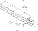
FIGS. 3 to 5 are perspective views illustrating various shapes of the electrode assembly according to the first embodiment of the present invention. -
FIG. 6 is a flowchart illustrating a method for manufacturing the electrode assembly according to the first embodiment of the present invention. -
FIG. 7 is a perspective view of an electrode assembly according to a second embodiment of the present invention. -
FIG. 8 is a front view of the electrode assembly according to the second embodiment of the present invention. -
FIG. 9 is a graph illustrating experimental results of the present invention. - Hereinafter, embodiments of the present invention will be described in detail with reference to the accompanying drawings in such a manner that the technical idea of the present invention may easily be carried out by a person with ordinary skill in the art to which the invention pertains. The present invention may, however, be embodied in different forms and should not be construed as limited to the embodiments set forth herein. In the drawings, anything unnecessary for describing the present invention will be omitted for clarity, and also like reference numerals in the drawings denote like elements.
- The front view of
FIG. 2 refers to a view when viewed in an 'A' direction ofFIG. 1 . - An electrode assembly according to a first embodiment of the present invention has a structure in which a plurality of unit electrodes and a plurality of separators are alternately laminated. The unit electrode may be manufactured by a plurality of electrodes, each of which is entirely made of a solid electrode mixture, to each other without a collector. Thus, the unit electrode having a novel structure may be newly designed according to a direction in which the plurality of electrodes are connected to each other.
- For example, as illustrated in
FIGS. 1 and2 , anelectrode assembly 100 according to the first embodiment of the present invention has a structure in which a plurality ofunit electrodes 110 and a plurality ofseparators 120 are alternately laminated. Each of theunit electrodes 110 is formed by connecting a plurality of electrodes to each other, and the entire electrode is made of an electrode mixture having a solid shape. - That is, the plurality of
unit electrodes 110 comprise afirst unit electrode 111 and asecond unit electrode 112, which have polarities different from each other. Thefirst unit electrode 111 is formed by a plurality offirst electrodes 111a, each of which is entirely made of a solid first electrode mixture, to each other, and thesecond unit electrode 112 is formed by a plurality ofsecond electrodes 112a, each of which is entirely made of a solid second electrode mixture, to each other. - Here, since the first or
second electrode second electrodes 111a or 112b may be connected to each other in an area or thickness direction of the electrode. Thus, the first orsecond unit electrode electrode assembly 100 comprising the first andsecond unit electrodes separator 120 may be realized. - An embodiment of the
electrode assembly 100 that is newly designed as described above will be described as follows. - First, as illustrated in
FIG. 3 , in the electrode assembly, the plurality offirst electrodes 111a or the plurality ofsecond electrodes 112a may lengthily extend in an one area direction of the electrode to realize aunit electrode 110 comprising thefirst unit electrode 111 and the second unit electrode, each of which has a predetermined length. Therefore, anelectrode assembly 100 having a predetermined length and comprising thefirst unit electrode 111, thesecond unit electrode 112, each of which has the predetermined area, and aseparator 120 may be realized. - Second, as illustrated in
FIG. 1 , the plurality offirst electrodes 111a or the plurality ofsecond electrodes 112a may be connected to each other in all area directions of the electrode to realize aunit electrode 110 comprising thefirst unit electrode 111 and thesecond unit electrode 112, each of which has a predetermined area. Therefore, anelectrode assembly 100 having a predetermined area and comprising thefirst unit electrode 111, thesecond unit electrode 112, each of which has the predetermined area, and aseparator 120 may be realized. - Third, as illustrated in
FIG. 4 , in the electrode assembly, the plurality offirst electrodes 111a or the plurality ofsecond electrodes 112a may be connected to each other in a thickness direction of an electrode to realize aunit electrode 110 comprising thefirst unit electrode 111 and thesecond unit electrode 112, each of which has a predetermined thickness. Therefore, anelectrode assembly 100 having a predetermined thickness and comprising thefirst unit electrode 111, thesecond unit electrode 112, each of which has the predetermined thickness, and aseparator 120 may be realized. - Fourth, the plurality of
first electrodes 111a or the plurality ofsecond electrodes 112a may be connected to each other in all of an area direction and a thickness direction of the electrode to realize aunit electrode 110 comprising thefirst unit electrode 111 and thesecond unit electrode 112, each of which has a predetermined area and thickness. Therefore, anelectrode assembly 100 having a predetermined area and thickness and comprising thefirst unit electrode 111, thesecond unit electrode 112, each of which has the predetermined area and thickness, and theseparator 120 may be realized. - Fifth, as illustrated in
FIG. 5 , in an electrode assembly, a plurality offirst electrodes 111a or a plurality ofsecond electrodes 112a may be irregularly connected to each other in an area direction and thickness direction of an electrode to provide aunit electrode 110 comprising afirst unit electrode 111 and asecond unit electrode 112, each of which has a new shape. Therefore, anelectrode assembly 100 having a new shape and comprising thefirst unit electrode 111, thesecond unit electrode 112, each of which has the new shape, and aseparator 120 may be realized. Particularly, theunit electrode 110 and theelectrode assembly 100 may be newly designed to match the inner space of a battery case that is designed to be compact through the irregular connection of the electrodes as described above to significantly improve marketability. - Sixth, the plurality of
first electrodes 111a or the plurality ofsecond electrodes 112a may be connected to each other in directions different from each other to realize aunit electrode 110 comprising thefirst unit electrode 111 and thesecond unit electrode 112, which have shapes different from each other. Therefore, anelectrode assembly 100 comprising thefirst unit electrode 111, thesecond unit electrode 112, which have the shapes different from each other, and theseparator 120 may be newly designed. - That is, the number of
first electrodes 111a and the connection direction of thefirst electrodes 111a may be different from the number ofsecond electrodes 112a and the connection direction of thesecond electrodes 112a. For example, an electrode assembly having a structure that gradually decreases in width from the lowermost end to the uppermost end thereof, an electrode assembly having a screw shape that gradually rotates in one direction from the lowermost end to the uppermost end thereof, or an electrode assembly having a hollow defined in a vertical direction may be realized. - The electrode may be made of a solid electrode mixture. The solid electrode mixture may be formed by mixing at least one or more of a solid conductive material and a solid binder with an solid electrode active material. Thus, the electrode has a polarity through the electrode active material, has a conductivity through the conductive material, and has coupling and adhesion between the electrode active material and the conductive material through the binder.
- For example, the
first electrode 111a is formed by mixing the conductive material and the binder with a solid first electrode active material, and thesecond electrode 112a is formed by mixing the conductive material and the binder with a solid second electrode active material. - Thus, each of the plurality of electrodes may be made of the solid electrode mixture without the collector, and thus, all surfaces of the electrode may have adhesion. Therefore, the
first unit electrode 111 and thesecond unit electrode 112, which are integrated with each other, may be realized. - Also, each of the plurality of electrodes may be made of the solid electrode mixture without the collector, and thus, all surfaces of the electrode may have conductivity. Therefore, the
first unit electrode 111 and thesecond unit electrode 112, which have conductivity and are integrated with each other, may be realized. - The electrode assembly according to an embodiment of the present invention comprises an
electrode tab 130 attached to theunit electrode 110, and theelectrode tab 130 is attached to at least one or more of an entire surface or an edge surface of theunit electrode 110. - For example, referring to
FIGS. 1 and2 , theelectrode tab 130 may comprise first andsecond electrode tabs second unit electrodes second electrode tabs unit electrode 110. - Here, the
first electrode tab 131 may have specific resistance less than that of thesecond electrode tab 132. That is, when theunit electrode 110 is charged at the set charging rate or less, the charging may be performed through thefirst electrode tab 131. When theunit electrode 110 is charged at the set charging rate or more, the charging may be performed through thesecond electrode tab 132. - That is, when the
unit electrode 110 is charged at the set charging rate or more, the charging may be performed through thesecond electrode tab 132 having the specific resistance greater than that of thefirst electrode tab 131, and thus, theunit electrode 110 may be heated at a temperature higher than that of thefirst electrode tab 131. Thus, as the temperature of theunit electrode 110 increases, the metal charging performance may be improved to improve the charging rate of theunit electrode 110. - The first unit electrode may be a positive unit electrode, and the second unit electrode may be a negative unit electrode. That is, the negative unit electrode does not well increase in temperature when compared to the positive unit electrode, and thus, the charging performance may be deteriorated. To prevent this, the
second electrode tab 132 having high specific resistance may be connected to the negative unit electrode, and thefirst electrode tab 131 having low specific resistance may be connected to the positive unit electrode. Thus, when charging, the temperature of the negative unit electrode may increase more effectively, and as a result, the charging performance of the negative unit electrode may be improved. - Here, a
heating wire 133 may be further attached to thesecond unit electrode 112. Theheating wire 133 may allow thesecond unit electrode 112, which is the negative unit electrode, to increase in temperature, thereby improving the charging performance of 112. That is, the negative unit electrode may increase in temperature largely through the heating wire to improve the charging performance of the negative unit electrode so as to correspond to the charging performance of the positive unit electrode, and as a result, the charging performance of the electrode assembly may be improved. - Particularly, each of the first and
second electrode tabs second unit electrodes electrode tab 130 may be adjusted to match the shape of the battery case to significantly improve a degree of freedom in design of the secondary battery. - The
electrode tab 130 may be provided as an electrode wire having flexibility and conductivity. Thus, theelectrode tab 130 may be bent to match an inner space of a battery case (not shown) in which theelectrode assembly 100 is accommodated and thus effectively accommodate theelectrode assembly 100. - As illustrated in
FIG. 1 , theelectrode tab 130 may be attached to a top surface of the unit electrode to effectively utilize a side space of the unit electrode, thereby realizing a more compact electrode assembly. - Thus, the
electrode assembly 100 comprising the above-described constituents according to the first embodiment of the present invention may realize the unit electrode having a new structure by using the electrode made of the solid electrode mixture. - Hereinafter, a method for manufacturing the electrode assembly according to the first embodiment of the present invention will be described.
- As illustrated in
FIG. 6 , a method for manufacturing the electrode assembly according to the first embodiment of the present invention comprises an electrode manufacturing step (S10) of compressing a solid electrode mixture to manufacture a plurality of electrodes, a unit electrode manufacturing step (S20) of connecting the plurality of electrodes to each other to manufacture unit electrodes, an electrode tab attachment step (S30) of attaching anelectrode tab 130 comprising first andsecond electrode tabs - The electrode manufacturing step (S10) comprises an electrode mixture manufacturing process and an electrode manufacturing process. In the electrode mixture manufacturing process, at least one or more of a solid conductive material and a solid binder are mixed with a solid electrode active material at a set ratio to manufacture the electrode mixture. For example, in the electrode mixture manufacturing process, a first electrode active material, the conductive material, and the binder are mixed with each other to manufacture a first electrode mixture, and a second electrode active material, the conductive material, and the binder are mixed with each other to manufacture a second electrode mixture.
- In the electrode manufacturing process, the electrode mixture is inserted into a mold having the form of the electrode to strongly press the electrode mixture, thereby manufacturing an electrode. For example, the first electrode mixture is pressed to manufacture a plurality of
first electrodes 111a, and the second electrode mixture is pressed to manufacture a plurality ofsecond electrodes 112a. Here, each of thefirst electrodes 111a and thesecond electrodes 112a does not comprise a collector. Thus, each of thefirst electrode 111a and thesecond electrode 112a may have conductivity and adhesion on an entire surface thereof. - The electrode manufacturing step (S10) further comprises a process of dry mixing the electrode active material, the conductive material, and the binder under a high stirring rate condition.
- For example, in a positive electrode manufacturing step, the positive electrode active material, the conductive material, and the binder are mixed with each other under the high stirring rate condition. Here, although not particularly limited, the positive electrode active material uses a general positive electrode active material, e.g., an alkali metal, an alkaline earth metal, a Group 13 element, a Group 14 element, a Group 15 element, a transition metal, a rare earth element, or lithium-containing metal oxide comprising a combination of the elements. Also, chalcogenide-based compounds may be also applied. As a nonlimiting example, lithium transition metal oxide such as LiMxOy(M = Co, Ni, Mn, CoaNibMnc) (for example, , lithium manganese composite oxides such as LiMn2O4, lithium nickel oxides such as LiNiO2, lithium cobalt oxides such as LiCoO2, and materials obtained by substituting a portion of manganese, nickel, and cobalt of the oxides with other general transition metals or lithium-containing vanadium oxide)-based positive active materials or a chalcogenide (for example, manganese dioxide, titanium disulfide, molybdenum disulfide, etc.)-based positive compounds may be applied.
- More particularly, the positive electrode active material may be a lithium transition metal oxide-based positive electrode active material. For example, the positive electrode active material may be selected from the group consisting of LiCoO2, LiNiO2, LiMn2O4, Li4Mn5O12, LiFePO4, Li(CoxNi1-x)O2 (0.5≤x<1), and LiaNibCocX1dX2eO2 (each of X1 and X2 independently represent at least one element selected from the group consisting of Mn, Al, Mg, Ti, Zr, Fe, V, W, Si, and Sn; where 0.8≤ a≤ = 1.3, 0.1 ≤ b< 1.0, 0.1 ≤ c<1.0, 0 ≤ d<1, 0≤ e<1).
- The conductive material may be natural graphite, artificial graphite, carbon black, acetylene black-based or Gulf Oil Company products, or a mixture of one or more kinds of the materials.
- The binder may comprise general binders used in the composition for forming the positive electrode. For example, polytetrafluoroethylene (PTFE), polyvinylidene fluoride (PVdF) or a copolymer thereof, styrene butadiene rubber (SBR), cellulose, and the like may be used as the binder.
- In the stirring speed condition, a stirrer may operate at a stirring speed of 500 rpm to 5,000 rpm, preferably, 2,000 rpm to 3,000 rpm.
- The binder may have a content of 0.5 parts by weight to 20 parts by weight, preferably 5 parts by weight to 10 parts by weight based on 100 parts by weight of the total weight of the positive electrode active material and the conductive material.
- In the unit electrode manufacturing step (S20), the plurality of electrodes are connected to each other to manufacture a unit electrode having a novel structure. For example, in the unit electrode manufacturing step (S20), the plurality of first or
second electrodes second unit electrode second electrodes second unit electrodes second electrodes second unit electrode - Particularly, in the unit electrode manufacturing step (S20), when the plurality of electrodes are irregularly connected to each other, a unit electrode having a shape of "" , "
 " , "
" , " " , or "H" may be manufactured.
- The unit electrode manufacturing step (S20) may further comprise a process of thermally fusing the electrode. In the process of thermally fusing the electrode, heat and a pressure may be applied to the unit electrode in which the plurality of electrodes are connected to each other to activate adhesion between the plurality of electrodes, thereby manufacturing an integrated unit electrode.
- After the unit electrode manufacturing step (S20), an electrode tab attachment step (S30) of attaching an
electrode tab 130 to theunit electrode 110 may be further performed. - In the electrode tab attachment step (S30), the first and
second electrode tabs second unit electrode second electrode tabs first unit electrode 111, and all of the first andsecond electrode tabs second unit electrode 112. Here, the first orsecond electrode tab second unit electrode - Particularly, the electrode tab attachment step (S30) may further comprise a process of thermally fusing the electrode tab to more firmly attach the electrode tab. In the process of thermally fusing the electrode tab, heat and a pressure may be applied to the electrode tab attached to the unit electrode to more firmly attach the electrode tab to the unit electrode.
- Here, the
first electrode tab 131 and thesecond electrode tab 132 may have different specific resistance. - For example, the
first electrode tab 131 has specific resistance less than that of thesecond electrode tab 132 and thus is used when the unit electrode is charged at the set charging rate or less. On the other hand, thesecond electrode tab 132 has specific resistance greater than that of thefirst electrode tab 131 and thus is used when the unit electrode is rapidly charged at the set charging speed or more. That is, when the unit electrode is charged, thesecond electrode tab 132 having the specific resistance greater than that of thefirst electrode tab 131 may more effectively increase in temperature that is higher than that of the unit electrode. Thus, as the temperature of the unit electrode increases, the rapid charging performance may be improved. - The
electrode tab 130 may be formed by using an electrode wire having flexibility and conductivity. Thus, although theelectrode tab 130 attached to theunit electrode 110 is attached at an erroneous position, the position of theelectrode tab 130 may be corrected through the flexibility of theelectrode tab 130. - In the electrode assembly manufacturing step (S40), the plurality of
unit electrodes 110, each of which has the novel structure, and one ormore separators 120 are vertically laminated to manufacture theelectrode assembly 100. - That is, the plurality of
unit electrodes 110 comprise afirst unit electrode 111 and asecond unit electrode 112. Aseparator 120 may be disposed between thefirst unit electrode 111 and thesecond unit electrode 112 to manufacture theelectrode assembly 100. - In the electrode assembly charging step (S50), a voltage is supplied to the
electrode tab 110 to charge theelectrode assembly 100. Here, the electrode assembly charging step (S50) comprises a process of charging theelectrode assembly 100 by using thefirst electrode tab 111 having the low specific resistance when the unit electrode is charged at the set charging rate or less and a process of charging theelectrode assembly 100 by using thesecond electrode tab 112 having the high specific resistance when the unit electrode is charged at the set charging rate or more. - In addition, in the electrode assembly charging step (S50), when the rapid charging is performed, the
electrode assembly 100 may be charged by using all of the first andsecond electrode tabs - Particularly, when the unit electrode is rapidly charged at the set charging value or more, the electrode assembly charging step (S50) may further comprise a process of allowing the unit electrode to increase in temperature through the
heating wire 133. Thus, as the temperature of the unit electrode increases effectively, the charging performance may be improved, and as a result, the unit electrode may be rapidly charged more effectively. - Hereinafter, in descriptions of another embodiment of the present invention, constituents of the second embodiment having the same constituent and function as the first embodiment have been given the same reference numeral in the drawings, and thus duplicated description will be omitted.
- As illustrated in
FIGS. 7 and8 , an electrode assembly 100' according to a second embodiment of the present invention comprises a plurality ofunit electrodes 110 formed by connecting a plurality of electrodes made of a solid electrode mixture to each other, aseparator 120 interposed between the plurality ofunit electrodes 110, and anelectrode tab 130 attached to theunit electrode 110. - Here, the plurality of
unit electrodes 110 comprise afirst unit electrode 111 and asecond unit electrode 112. Thefirst unit electrode 111 is provided as a positive unit electrode, and thesecond unit electrode 112 is provided as a negative unit electrode. - When charging, the second unit electrode that is the negative unit electrode may have a temperature less than that of the first unit electrode that is the positive unit electrode to deteriorate the charging performance.
- To solve this problem, in the electrode assembly 100' according to the second embodiment of the present invention, a
heating wire 133 may be further attached to the second unit electrode that is the negative unit electrode. When the electrode assembly 100' is charged, theheating wire 133 may allow thesecond unit electrode 112 that is the negative unit electrode to increase in temperature, thereby improving the rapid charging performance of the second unit electrode. - Thus, the electrode assembly 100' according to the second embodiment of the present invention may have a feature in which the
heating wire 133 is further attached to the second unit electrode that is the negative electrode unit electrode. Therefore, the second unit electrode that is the negative unit electrode may increase in temperature to improve the charging performance, thereby improving the charging efficiency of the electrode assembly. - When measuring a temperature and resistance variation of the second unit electrode, which is a negative unit electrode, while slow and rapid charging the secondary battery comprising the electrode assembly 100' according to the second embodiment of the present invention, which is manufactured as described above, a resistance graph of
FIG. 9 may be obtained. - First: when measuring the resistance variation of the second unit electrode, which is the negative unit electrode, while charging the electrode assembly 100' by using the
first electrode tab 111 having the low specific resistance during the slow charging, a resistance graph such as a curve A ofFIG. 9 may be obtained. - That is, referring to the curve A of
FIG. 9 , it is seen that the temperature of the second unit electrode, which is the negative unit electrode, is 15°C, and resistance of approximately 1.64 ohm occurs. - Second: when measuring the resistance variation of the second unit electrode, which is the negative unit electrode, while charging the electrode assembly 100' by further using the
second electrode tab 112 having the high specific resistance during the rapid charging, a resistance graph such as a curve B ofFIG. 9 may be obtained. - That is, referring to the curve B of
FIG. 9 , it is seen that the temperature of the second unit electrode, which is the negative unit electrode, is 25°C, and resistance of approximately 0.73 ohm occurs. - That is to say, comparing the curves A and B of
FIG. 9 to each other, it is seen that, as thesecond electrode tab 112 having the high specific resistance is further used, the temperature of the second unit electrode that is the negative unit electrode increases by 10°C, and the resistance is reduced by approximately 0.91 ohm during the rapid charging when compared to the temperature and resistance of the second unit electrode during the slow charging. - Third: when measuring the resistance variation of the second unit electrode, which is the negative unit electrode, while charging the electrode assembly 100' by further using the
second electrode tab 112 having the high specific resistance and simultaneously allowing the second unit electrode, which is the negative unit electrode, to increase in temperature through the heating wire during the rapid charging, a resistance graph such as a curve C ofFIG. 9 may be obtained. - That is, referring to the curve C of
FIG. 9 , it is seen that the temperature of the second unit electrode, which is the negative unit electrode, is 35°C, and resistance of approximately 0.3 ohm occurs. - That is to say, comparing the curves B and C of
FIG. 9 to each other, it is seen that the temperature of the second unit electrode that is the negative unit electrode increases by 10°C, and the resistance is reduced by approximately 0.43 ohm during the rapid charging in which the heating wire is used. - Accordingly, as the results of the above experiment, it may be seen that when the temperature of the second unit electrode, which is the negative unit electrode, increases, the resistance decreases. Therefore, as the resistance decreases, the charging performance may be improved, thereby the charging efficiency of the electrode assembly.
- Accordingly, the scope of the present invention is defined by the appended claims rather than the foregoing description and the exemplary embodiments described therein. Various modifications made within the meaning of an equivalent of the claims of the invention and within the claims are to be regarded to be in the scope of the present invention.
Claims (12)
- An electrode assembly comprising:a plurality of unit electrodes formed by connecting a plurality of electrodes made of an electrode mixture having a solid shape to each other;a separator interposed between the plurality of unit electrodes; andan electrode tab attached to the unit electrode,wherein the electrode tab comprises first and second electrode tabs, which are respectively attached to the unit electrodes and have different specific resistance.
- The electrode assembly of claim 1, wherein the first electrode tab has specific resistance less than that of the second electrode tab and is used when the unit electrode is charged at a set charging rate or less, and
the second electrode tab has specific resistance greater than that of the first electrode tab and is used when the unit electrode is rapidly charged at the set charging rate or more. - The electrode assembly of claim 1, wherein the plurality of unit electrodes comprise a first unit electrode and a second unit electrode, and
a heating wire is further attached to the second unit electrode. - An electrode assembly comprising:a plurality of unit electrodes formed by connecting a plurality of electrodes made of an electrode mixture having a solid shape to each other;a separator interposed between the plurality of unit electrodes; andan electrode tab attached to the unit electrode,wherein the plurality of unit electrodes comprise a first unit electrode and a second unit electrode, anda heating wire is further attached to the second unit electrode.
- The electrode assembly of claim 4, wherein the first unit electrode is provided as a positive unit electrode, and
the second unit electrode is provided as a negative unit electrode. - The electrode assembly of claim 1 or 4, wherein the electrode mixture is formed by further mixing at least one or more of a conductive material or a binder with an electrode active material.
- The electrode assembly of claim 1 or 4, wherein the plurality of electrodes are connected to each other in an area or thickness direction of the electrode.
- The electrode assembly of claim 1 or 4, wherein the plurality of electrodes forms an integrated unit electrode by an adhesive property of an outer surface of the electrode, and
the integrated unit electrode forms a unit electrode having integrated conductivity by conductivity of the electrode. - The electrode assembly of claim 1 to 4, wherein the electrode tab is provided as an electrode wire having flexibility.
- A method for manufacturing an electrode assembly, the method comprising:an electrode manufacturing step (S10) of compressing a solid electrode mixture to manufacture a plurality of electrodes;a unit electrode manufacturing step (S20) of connecting the plurality of electrodes to each other in an area or thickness direction to manufacture plurality of unit electrodes;an electrode tab attachment step (S30) of attaching an electrode tab 130 to the plurality of unit electrodes; andan electrode assembly manufacturing step (S40) of interposing a separator between the plurality of unit electrodes to which the electrode tab is attached to manufacture an electrode assembly,wherein, in the electrode tab attachment step (S30), the electrode tab comprises first and second electrode tabs having different specific resistance.
- The method of claim 10, after the electrode assembly manufacturing step (S40), further comprising an electrode assembly charging step (S50) of charging the electrode assembly,
wherein the electrode assembly charging step (S50) comprises a process of charging the electrode assembly by using the first electrode tab having low specific resistance when the unit electrode is charged at a set charging rate or less and a process of charging the electrode assembly by using the second electrode tab having high specific resistance when the unit electrode is charged at the set charging rate or more. - The method of claim 11, wherein, when the unit electrode is rapidly charged at the set charging rate or more, the electrode assembly charging step (S50) further comprising a process of allowing the unit electrode to increase in temperature through the heating wire.
Applications Claiming Priority (2)
| Application Number | Priority Date | Filing Date | Title |
|---|---|---|---|
| KR1020180084109A KR102402612B1 (en) | 2018-07-19 | 2018-07-19 | Electrode assembly and method for preparing the same |
| PCT/KR2019/007817 WO2020017781A1 (en) | 2018-07-19 | 2019-06-27 | Electrode assembly and manufacturing method thereof |
Publications (2)
| Publication Number | Publication Date |
|---|---|
| EP3680976A1 true EP3680976A1 (en) | 2020-07-15 |
| EP3680976A4 EP3680976A4 (en) | 2021-01-06 |
Family
ID=69164816
Family Applications (1)
| Application Number | Title | Priority Date | Filing Date |
|---|---|---|---|
| EP19838352.3A Pending EP3680976A4 (en) | 2018-07-19 | 2019-06-27 | ELECTRODES AND ITS MANUFACTURING PROCESS |
Country Status (5)
| Country | Link |
|---|---|
| US (2) | US11508985B2 (en) |
| EP (1) | EP3680976A4 (en) |
| KR (1) | KR102402612B1 (en) |
| CN (1) | CN111213270B (en) |
| WO (1) | WO2020017781A1 (en) |
Families Citing this family (2)
| Publication number | Priority date | Publication date | Assignee | Title |
|---|---|---|---|---|
| KR102402612B1 (en) * | 2018-07-19 | 2022-05-27 | 주식회사 엘지에너지솔루션 | Electrode assembly and method for preparing the same |
| CN111864288B (en) * | 2020-08-18 | 2024-12-03 | 广州市融成锂能锂电池有限公司 | A soft pack battery split capacity conjoined plate and split capacity method thereof |
Family Cites Families (18)
| Publication number | Priority date | Publication date | Assignee | Title |
|---|---|---|---|---|
| JP3403678B2 (en) | 1999-09-10 | 2003-05-06 | 日本碍子株式会社 | Method for producing lithium secondary battery and wound electrode body |
| US6503658B1 (en) * | 2001-07-11 | 2003-01-07 | Electro Energy, Inc. | Bipolar electrochemical battery of stacked wafer cells |
| JP2004047239A (en) | 2002-07-10 | 2004-02-12 | Nissan Motor Co Ltd | Thin battery, assembled battery, composite assembled battery and vehicle equipped with the same |
| US20040185332A1 (en) * | 2003-03-21 | 2004-09-23 | Moltech Corporation | Tabs for electrochemical cells |
| KR100888284B1 (en) | 2006-07-24 | 2009-03-10 | 주식회사 엘지화학 | Electrode assembly with minimized resistance difference between electrodes of tap-lead joint and electrochemical cell |
| US9236594B2 (en) | 2007-02-16 | 2016-01-12 | Namics Corporation | Lithium ion secondary battery and process for manufacturing the same |
| US8092936B2 (en) | 2007-12-25 | 2012-01-10 | Byd Co. Ltd. | Electrochemical cell having a coiled core |
| JP5132783B2 (en) | 2007-12-25 | 2013-01-30 | ビーワイディー カンパニー リミテッド | Battery system having a heating terminal |
| US8708321B2 (en) | 2011-07-29 | 2014-04-29 | Samsung Sdi Co., Ltd. | Insulating film attaching jig and battery cell manufactured by using the same |
| US10199658B2 (en) | 2013-03-15 | 2019-02-05 | Eaglepicher Technologies, Llc | Wound thermal batteries and methods of manufacturing the same |
| US9478829B2 (en) * | 2013-05-16 | 2016-10-25 | Ec Power, Llc | Rechargeable battery with multiple resistance levels |
| KR102264546B1 (en) * | 2014-08-29 | 2021-06-14 | 에스케이이노베이션 주식회사 | Electrode assembly for secondary battery |
| KR101755919B1 (en) * | 2015-12-08 | 2017-07-07 | 현대자동차주식회사 | Heating device for battery |
| KR101781487B1 (en) | 2016-03-23 | 2017-09-27 | 주식회사 비츠로셀 | Slide fastening type single flow battery stack |
| KR20160086795A (en) | 2016-07-08 | 2016-07-20 | 현대자동차주식회사 | A solid-state battery and a method for manufacturing it |
| CN106252659A (en) * | 2016-09-30 | 2016-12-21 | 上海空间电源研究所 | Integrated flexible thin film lithium sulfur or lithium ion battery cell, battery and preparation method |
| KR102402611B1 (en) | 2018-07-09 | 2022-05-27 | 주식회사 엘지에너지솔루션 | Electrode assembly and method for preparing the same |
| KR102402612B1 (en) * | 2018-07-19 | 2022-05-27 | 주식회사 엘지에너지솔루션 | Electrode assembly and method for preparing the same |
-
2018
- 2018-07-19 KR KR1020180084109A patent/KR102402612B1/en active Active
-
2019
- 2019-06-27 WO PCT/KR2019/007817 patent/WO2020017781A1/en not_active Ceased
- 2019-06-27 US US16/651,564 patent/US11508985B2/en active Active
- 2019-06-27 CN CN201980004755.XA patent/CN111213270B/en active Active
- 2019-06-27 EP EP19838352.3A patent/EP3680976A4/en active Pending
-
2022
- 2022-10-14 US US17/966,706 patent/US11955594B2/en active Active
Also Published As
| Publication number | Publication date |
|---|---|
| US20200266476A1 (en) | 2020-08-20 |
| CN111213270A (en) | 2020-05-29 |
| WO2020017781A1 (en) | 2020-01-23 |
| CN111213270B (en) | 2023-10-10 |
| EP3680976A4 (en) | 2021-01-06 |
| KR102402612B1 (en) | 2022-05-27 |
| KR20200009573A (en) | 2020-01-30 |
| US20230033456A1 (en) | 2023-02-02 |
| US11955594B2 (en) | 2024-04-09 |
| US11508985B2 (en) | 2022-11-22 |
Similar Documents
| Publication | Publication Date | Title |
|---|---|---|
| JP6160602B2 (en) | Lithium ion secondary battery | |
| JP5880956B2 (en) | SECONDARY BATTERY ELECTRODE, MANUFACTURING METHOD THEREOF, AND NON-AQUEOUS ELECTROLYTE SECONDARY BATTERY HAVING THE SECONDARY BATTERY ELEMENT | |
| US20100285352A1 (en) | Electrochemical cells with tabs | |
| KR101551523B1 (en) | Positive-electrode active material with improved output and safety, and lithium secondary battery including the same | |
| EP3142171A1 (en) | Electrode stack structure and battery having electrode stack structure | |
| JP2007250299A (en) | Nonaqueous electrolyte solution secondary battery | |
| CN101103475A (en) | Negative electrode for lithium ion secondary battery, method for producing same, lithium ion secondary battery, and method for producing same | |
| JP2020510980A (en) | Strip type electrode used for cylindrical jelly roll and lithium secondary battery including the same | |
| US11394089B2 (en) | Electrode assembly and method for manufacturing the same | |
| US11955594B2 (en) | Electrode assembly and comprising connected plurality of unit electrodes | |
| US12249702B2 (en) | Method for manufacturing a secondary battery | |
| US11011743B2 (en) | Lithium ion secondary battery | |
| JP2013131381A (en) | Nonaqueous electrolyte secondary battery | |
| KR20150016018A (en) | Composite electrode comprising different electrode active material and electrode assembly | |
| JP6858144B2 (en) | Secondary battery and its manufacturing method | |
| KR101926129B1 (en) | Electrode assembly for secondary battery | |
| KR100696826B1 (en) | Electrode plate and lithium secondary battery having same | |
| CN119480915A (en) | Electrode manufacturing method, electrode and battery | |
| KR20060027255A (en) | Manufacturing method of electrode plate for lithium secondary battery | |
| KR20060027254A (en) | Electrode plate for lithium secondary battery |
Legal Events
| Date | Code | Title | Description |
|---|---|---|---|
| STAA | Information on the status of an ep patent application or granted ep patent |
Free format text: STATUS: THE INTERNATIONAL PUBLICATION HAS BEEN MADE |
|
| PUAI | Public reference made under article 153(3) epc to a published international application that has entered the european phase |
Free format text: ORIGINAL CODE: 0009012 |
|
| STAA | Information on the status of an ep patent application or granted ep patent |
Free format text: STATUS: REQUEST FOR EXAMINATION WAS MADE |
|
| 17P | Request for examination filed |
Effective date: 20200325 |
|
| AK | Designated contracting states |
Kind code of ref document: A1 Designated state(s): AL AT BE BG CH CY CZ DE DK EE ES FI FR GB GR HR HU IE IS IT LI LT LU LV MC MK MT NL NO PL PT RO RS SE SI SK SM TR |
|
| AX | Request for extension of the european patent |
Extension state: BA ME |
|
| A4 | Supplementary search report drawn up and despatched |
Effective date: 20201203 |
|
| RIC1 | Information provided on ipc code assigned before grant |
Ipc: H01M 4/02 20060101ALI20201127BHEP Ipc: H01M 2/26 20060101ALI20201127BHEP Ipc: H01M 10/44 20060101ALI20201127BHEP Ipc: H01M 10/04 20060101AFI20201127BHEP Ipc: H01M 10/6571 20140101ALI20201127BHEP Ipc: H01M 4/04 20060101ALI20201127BHEP Ipc: H01M 2/34 20060101ALI20201127BHEP Ipc: H01M 4/139 20100101ALI20201127BHEP Ipc: H01M 10/0585 20100101ALI20201127BHEP Ipc: H01M 4/13 20100101ALI20201127BHEP |
|
| STAA | Information on the status of an ep patent application or granted ep patent |
Free format text: STATUS: EXAMINATION IS IN PROGRESS |
|
| 17Q | First examination report despatched |
Effective date: 20210817 |
|
| DAV | Request for validation of the european patent (deleted) | ||
| DAX | Request for extension of the european patent (deleted) | ||
| RAP1 | Party data changed (applicant data changed or rights of an application transferred) |
Owner name: LG ENERGY SOLUTION LTD. |
|
| RAP3 | Party data changed (applicant data changed or rights of an application transferred) |
Owner name: LG ENERGY SOLUTION, LTD. |