EP3680930A1 - Storage system and purge method in storage system - Google Patents
Storage system and purge method in storage system Download PDFInfo
- Publication number
- EP3680930A1 EP3680930A1 EP18854967.9A EP18854967A EP3680930A1 EP 3680930 A1 EP3680930 A1 EP 3680930A1 EP 18854967 A EP18854967 A EP 18854967A EP 3680930 A1 EP3680930 A1 EP 3680930A1
- Authority
- EP
- European Patent Office
- Prior art keywords
- nozzle
- shelf
- controller
- purge
- clean gas
- Prior art date
- Legal status (The legal status is an assumption and is not a legal conclusion. Google has not performed a legal analysis and makes no representation as to the accuracy of the status listed.)
- Granted
Links
- 238000003860 storage Methods 0.000 title claims abstract description 28
- 238000010926 purge Methods 0.000 title claims description 95
- 238000000034 method Methods 0.000 title claims description 8
- 238000002360 preparation method Methods 0.000 claims abstract description 8
- 230000032258 transport Effects 0.000 claims description 48
- 239000007789 gas Substances 0.000 description 50
- 238000004140 cleaning Methods 0.000 description 16
- 239000000872 buffer Substances 0.000 description 7
- 238000010586 diagram Methods 0.000 description 6
- 230000004048 modification Effects 0.000 description 4
- 238000012986 modification Methods 0.000 description 4
- IJGRMHOSHXDMSA-UHFFFAOYSA-N Atomic nitrogen Chemical compound N#N IJGRMHOSHXDMSA-UHFFFAOYSA-N 0.000 description 3
- 239000004065 semiconductor Substances 0.000 description 3
- 235000012431 wafers Nutrition 0.000 description 3
- 230000003749 cleanliness Effects 0.000 description 2
- 238000011109 contamination Methods 0.000 description 2
- 229910001873 dinitrogen Inorganic materials 0.000 description 1
- 229910052757 nitrogen Inorganic materials 0.000 description 1
- 239000002245 particle Substances 0.000 description 1
- 230000010349 pulsation Effects 0.000 description 1
- 230000001960 triggered effect Effects 0.000 description 1
Images


Classifications
-
- H—ELECTRICITY
- H01—ELECTRIC ELEMENTS
- H01L—SEMICONDUCTOR DEVICES NOT COVERED BY CLASS H10
- H01L21/00—Processes or apparatus adapted for the manufacture or treatment of semiconductor or solid state devices or of parts thereof
- H01L21/67—Apparatus specially adapted for handling semiconductor or electric solid state devices during manufacture or treatment thereof; Apparatus specially adapted for handling wafers during manufacture or treatment of semiconductor or electric solid state devices or components ; Apparatus not specifically provided for elsewhere
- H01L21/677—Apparatus specially adapted for handling semiconductor or electric solid state devices during manufacture or treatment thereof; Apparatus specially adapted for handling wafers during manufacture or treatment of semiconductor or electric solid state devices or components ; Apparatus not specifically provided for elsewhere for conveying, e.g. between different workstations
- H01L21/67763—Apparatus specially adapted for handling semiconductor or electric solid state devices during manufacture or treatment thereof; Apparatus specially adapted for handling wafers during manufacture or treatment of semiconductor or electric solid state devices or components ; Apparatus not specifically provided for elsewhere for conveying, e.g. between different workstations the wafers being stored in a carrier, involving loading and unloading
- H01L21/67769—Storage means
-
- B—PERFORMING OPERATIONS; TRANSPORTING
- B65—CONVEYING; PACKING; STORING; HANDLING THIN OR FILAMENTARY MATERIAL
- B65G—TRANSPORT OR STORAGE DEVICES, e.g. CONVEYORS FOR LOADING OR TIPPING, SHOP CONVEYOR SYSTEMS OR PNEUMATIC TUBE CONVEYORS
- B65G1/00—Storing articles, individually or in orderly arrangement, in warehouses or magazines
-
- H—ELECTRICITY
- H01—ELECTRIC ELEMENTS
- H01L—SEMICONDUCTOR DEVICES NOT COVERED BY CLASS H10
- H01L21/00—Processes or apparatus adapted for the manufacture or treatment of semiconductor or solid state devices or of parts thereof
- H01L21/67—Apparatus specially adapted for handling semiconductor or electric solid state devices during manufacture or treatment thereof; Apparatus specially adapted for handling wafers during manufacture or treatment of semiconductor or electric solid state devices or components ; Apparatus not specifically provided for elsewhere
- H01L21/673—Apparatus specially adapted for handling semiconductor or electric solid state devices during manufacture or treatment thereof; Apparatus specially adapted for handling wafers during manufacture or treatment of semiconductor or electric solid state devices or components ; Apparatus not specifically provided for elsewhere using specially adapted carriers or holders; Fixing the workpieces on such carriers or holders
- H01L21/6735—Closed carriers
- H01L21/67389—Closed carriers characterised by atmosphere control
- H01L21/67393—Closed carriers characterised by atmosphere control characterised by the presence of atmosphere modifying elements inside or attached to the closed carrierl
-
- B—PERFORMING OPERATIONS; TRANSPORTING
- B65—CONVEYING; PACKING; STORING; HANDLING THIN OR FILAMENTARY MATERIAL
- B65G—TRANSPORT OR STORAGE DEVICES, e.g. CONVEYORS FOR LOADING OR TIPPING, SHOP CONVEYOR SYSTEMS OR PNEUMATIC TUBE CONVEYORS
- B65G1/00—Storing articles, individually or in orderly arrangement, in warehouses or magazines
- B65G1/02—Storage devices
- B65G1/04—Storage devices mechanical
- B65G1/0407—Storage devices mechanical using stacker cranes
- B65G1/0421—Storage devices mechanical using stacker cranes with control for stacker crane operations
-
- B—PERFORMING OPERATIONS; TRANSPORTING
- B65—CONVEYING; PACKING; STORING; HANDLING THIN OR FILAMENTARY MATERIAL
- B65G—TRANSPORT OR STORAGE DEVICES, e.g. CONVEYORS FOR LOADING OR TIPPING, SHOP CONVEYOR SYSTEMS OR PNEUMATIC TUBE CONVEYORS
- B65G1/00—Storing articles, individually or in orderly arrangement, in warehouses or magazines
- B65G1/02—Storage devices
- B65G1/04—Storage devices mechanical
- B65G1/137—Storage devices mechanical with arrangements or automatic control means for selecting which articles are to be removed
-
- H—ELECTRICITY
- H01—ELECTRIC ELEMENTS
- H01L—SEMICONDUCTOR DEVICES NOT COVERED BY CLASS H10
- H01L21/00—Processes or apparatus adapted for the manufacture or treatment of semiconductor or solid state devices or of parts thereof
- H01L21/67—Apparatus specially adapted for handling semiconductor or electric solid state devices during manufacture or treatment thereof; Apparatus specially adapted for handling wafers during manufacture or treatment of semiconductor or electric solid state devices or components ; Apparatus not specifically provided for elsewhere
- H01L21/673—Apparatus specially adapted for handling semiconductor or electric solid state devices during manufacture or treatment thereof; Apparatus specially adapted for handling wafers during manufacture or treatment of semiconductor or electric solid state devices or components ; Apparatus not specifically provided for elsewhere using specially adapted carriers or holders; Fixing the workpieces on such carriers or holders
- H01L21/6735—Closed carriers
- H01L21/67373—Closed carriers characterised by locking systems
-
- H—ELECTRICITY
- H01—ELECTRIC ELEMENTS
- H01L—SEMICONDUCTOR DEVICES NOT COVERED BY CLASS H10
- H01L21/00—Processes or apparatus adapted for the manufacture or treatment of semiconductor or solid state devices or of parts thereof
- H01L21/67—Apparatus specially adapted for handling semiconductor or electric solid state devices during manufacture or treatment thereof; Apparatus specially adapted for handling wafers during manufacture or treatment of semiconductor or electric solid state devices or components ; Apparatus not specifically provided for elsewhere
- H01L21/673—Apparatus specially adapted for handling semiconductor or electric solid state devices during manufacture or treatment thereof; Apparatus specially adapted for handling wafers during manufacture or treatment of semiconductor or electric solid state devices or components ; Apparatus not specifically provided for elsewhere using specially adapted carriers or holders; Fixing the workpieces on such carriers or holders
- H01L21/6735—Closed carriers
- H01L21/67389—Closed carriers characterised by atmosphere control
-
- H—ELECTRICITY
- H01—ELECTRIC ELEMENTS
- H01L—SEMICONDUCTOR DEVICES NOT COVERED BY CLASS H10
- H01L21/00—Processes or apparatus adapted for the manufacture or treatment of semiconductor or solid state devices or of parts thereof
- H01L21/67—Apparatus specially adapted for handling semiconductor or electric solid state devices during manufacture or treatment thereof; Apparatus specially adapted for handling wafers during manufacture or treatment of semiconductor or electric solid state devices or components ; Apparatus not specifically provided for elsewhere
- H01L21/677—Apparatus specially adapted for handling semiconductor or electric solid state devices during manufacture or treatment thereof; Apparatus specially adapted for handling wafers during manufacture or treatment of semiconductor or electric solid state devices or components ; Apparatus not specifically provided for elsewhere for conveying, e.g. between different workstations
- H01L21/67703—Apparatus specially adapted for handling semiconductor or electric solid state devices during manufacture or treatment thereof; Apparatus specially adapted for handling wafers during manufacture or treatment of semiconductor or electric solid state devices or components ; Apparatus not specifically provided for elsewhere for conveying, e.g. between different workstations between different workstations
- H01L21/67706—Mechanical details, e.g. roller, belt
-
- H—ELECTRICITY
- H01—ELECTRIC ELEMENTS
- H01L—SEMICONDUCTOR DEVICES NOT COVERED BY CLASS H10
- H01L21/00—Processes or apparatus adapted for the manufacture or treatment of semiconductor or solid state devices or of parts thereof
- H01L21/67—Apparatus specially adapted for handling semiconductor or electric solid state devices during manufacture or treatment thereof; Apparatus specially adapted for handling wafers during manufacture or treatment of semiconductor or electric solid state devices or components ; Apparatus not specifically provided for elsewhere
- H01L21/677—Apparatus specially adapted for handling semiconductor or electric solid state devices during manufacture or treatment thereof; Apparatus specially adapted for handling wafers during manufacture or treatment of semiconductor or electric solid state devices or components ; Apparatus not specifically provided for elsewhere for conveying, e.g. between different workstations
- H01L21/67703—Apparatus specially adapted for handling semiconductor or electric solid state devices during manufacture or treatment thereof; Apparatus specially adapted for handling wafers during manufacture or treatment of semiconductor or electric solid state devices or components ; Apparatus not specifically provided for elsewhere for conveying, e.g. between different workstations between different workstations
- H01L21/6773—Conveying cassettes, containers or carriers
-
- B—PERFORMING OPERATIONS; TRANSPORTING
- B65—CONVEYING; PACKING; STORING; HANDLING THIN OR FILAMENTARY MATERIAL
- B65G—TRANSPORT OR STORAGE DEVICES, e.g. CONVEYORS FOR LOADING OR TIPPING, SHOP CONVEYOR SYSTEMS OR PNEUMATIC TUBE CONVEYORS
- B65G1/00—Storing articles, individually or in orderly arrangement, in warehouses or magazines
- B65G1/02—Storage devices
-
- B—PERFORMING OPERATIONS; TRANSPORTING
- B65—CONVEYING; PACKING; STORING; HANDLING THIN OR FILAMENTARY MATERIAL
- B65G—TRANSPORT OR STORAGE DEVICES, e.g. CONVEYORS FOR LOADING OR TIPPING, SHOP CONVEYOR SYSTEMS OR PNEUMATIC TUBE CONVEYORS
- B65G2201/00—Indexing codes relating to handling devices, e.g. conveyors, characterised by the type of product or load being conveyed or handled
- B65G2201/02—Articles
- B65G2201/0297—Wafer cassette
-
- H—ELECTRICITY
- H01—ELECTRIC ELEMENTS
- H01L—SEMICONDUCTOR DEVICES NOT COVERED BY CLASS H10
- H01L21/00—Processes or apparatus adapted for the manufacture or treatment of semiconductor or solid state devices or of parts thereof
- H01L21/67—Apparatus specially adapted for handling semiconductor or electric solid state devices during manufacture or treatment thereof; Apparatus specially adapted for handling wafers during manufacture or treatment of semiconductor or electric solid state devices or components ; Apparatus not specifically provided for elsewhere
- H01L21/677—Apparatus specially adapted for handling semiconductor or electric solid state devices during manufacture or treatment thereof; Apparatus specially adapted for handling wafers during manufacture or treatment of semiconductor or electric solid state devices or components ; Apparatus not specifically provided for elsewhere for conveying, e.g. between different workstations
- H01L21/67703—Apparatus specially adapted for handling semiconductor or electric solid state devices during manufacture or treatment thereof; Apparatus specially adapted for handling wafers during manufacture or treatment of semiconductor or electric solid state devices or components ; Apparatus not specifically provided for elsewhere for conveying, e.g. between different workstations between different workstations
- H01L21/67733—Overhead conveying
Definitions
- the present invention relates to a storage system, such as a purge stocker, and a purge method in the storage system.
- Purge stockers have shelves and nozzles provided in the shelves; the nozzles are configured to be made in contact with valves in the bottoms of containers, such as FOUPs, stored on the shelves, and are configured to supply clean gas, such as nitrogen gas or clean dry air, into the containers.
- containers such as FOUPs
- Patent Document 1 JP4692584B
- Patent Document 2 JP5557061B
- Patent Document 2 JP5557061B
- This purge stocker has a reduced consumption amount of clean gas, since the cleaning is carried out just in the shelf assigned for the unloading position and since the purge is triggered by the start of movement of the transport apparatus.
- the present inventors have found cases where a container was connected with a not fully cleaned nozzle, because the transport apparatus had arrived at the shelf assigned for the unloading position before the completion of cleaning, and cases where the transport apparatus had to wait for the completion of the cleaning before the transfer of a container with the shelf.
- the object of the present invention is to provide a storage system and a purge method in the storage system, capable of fully cleaning nozzles before transferring containers to and on the corresponding shelves, with a reduced amount of clean gas consumption, and without phenomena such as delaying the transfer by the transport apparatus for waiting for the completion of the nozzle cleaning.
- a storage system comprises: a plurality of shelves, respectively provided with at least one nozzle for supplying clean gas into containers; a plurality of flow amount controlling devices, respectively controlling supply amount of said clean gas to said at least one nozzle; at least one transport apparatus transferring said containers to and from said shelves; and a controller controlling said at least one transport apparatus and said flow amount controlling devices.
- said controller is configured and programmed to make an assignment of at least one shelf in preparation for storing an incoming container and before the occurrence of said incoming container, and to control one of said flow amount controlling devices to supply said clean gas to said at least one nozzle in said at least one shelf, based upon said assignment.
- a purge method uses a storage system comprising: a plurality of shelves, respectively provided with at least one nozzle for supplying clean gas into containers; a plurality of flow amount controlling devices, respectively controlling supply amount of said clean gas to said at least one nozzle; at least one transport apparatus transferring said containers to and from said shelves; and a controller controlling said at least one transport apparatus and said flow amount controlling devices.
- the method according to the present invention comprises: making an assignment of at least one shelf in preparation for storing an incoming container and before the occurrence of said incoming container, by said controller; and supplying said clean gas to said at least one nozzle in said at least one shelf, based upon said assignment.
- said at least one shelf is assigned for storing the incoming container and the cleaning of the nozzle in the assigned shelf is started. Therefore, when the incoming container will arrive at the shelf, the nozzle will be fully cleaned. In addition, an enough time duration is present for the nozzle cleaning, and therefore, there arises no delay of transfer motion by the transport apparatus for unloading the incoming container to the shelf, due to waiting for the completion of the nozzle cleaning.
- said storage system is a purge stocker and is further provided with an entrance and dispatch port
- said at least one transport apparatus transports said incoming container between said entrance and dispatch port and said shelves
- said controller is further configured and programmed to make said assignment of said at least one shelf in advance, before said incoming container will arrive at said entrance and dispatch port.
- the assignment of the shelf, and the nozzle cleaning are commenced before the incoming container will arrive; and therefore, the nozzle is fully cleaned before the incoming container will arrive at the shelf.
- said controller is further configured and programmed to control said one of said flow amount controlling devices to intermittently supply said clean gas to said at least one nozzle in said at least one shelf.
- said controller is further configured and programmed to control said one of said flow amount controlling devices to intermittently supply said clean gas to said at least one nozzle in said at least one shelf.
- said at least one transport apparatus is provided with a transfer device entering into and unloading said incoming container on said shelves, and said controller is further configured and programmed to control said one of said flow amount controlling devices to supply a larger flow amount of said clean gas to said at least one nozzle, from when said transfer device starts advancement towards said at least one shelf and until completing unloading of said incoming container, than an amount before said transfer device starts advancement. Then, not only the nozzle but also the bottom (abutting the nozzle) of the incoming container held by the transfer device are made clean .
- Figs. 1-8 indicate a purge stocker 2 according to an embodiment.
- the purge stocker 2 is provided within a clean room and so on, and stores containers for semiconductor wafers, reticles, and so on.
- the purge stocker 2 is shut off from outside atmosphere by a wall 4, and the wall 4 is provided with a door 5.
- the purge stocker 2 is provided with a transport apparatus 6 and a plurality of shelves 14; the transport apparatus 6 is, for example, a stacker crane, but the species of the transport apparatus 6 is arbitrary.
- the transport apparatus 6 has a running vehicle 7 that runs on a rail 11 and supports a mast 8, and a carriage 9 elevates and lowers along the mast 8.
- the carriage 9 in the transport apparatus 6 is provided with a transfer device 10, such as a SCARA arm, a sliding fork, and so on, for transferring a container 16 between a shelf 14.
- a transfer device 10 such as a SCARA arm, a sliding fork, and so on
- the container 16 is a FOUP which stores semiconductor wafers and is provided with a valve in the bottom portion that receives clean gas from a nozzle in the shelf 14, and thus, the inside of the container is kept clean.
- the species of the container 16 is arbitrary, as long as the container 16 is configured to be purged by clean gas blown into from a nozzle of a shelf 14.
- Fig. 2 indicates the shelves 14.
- the shelf 14 is provided with a shelf support 18 having an opening 17; the transport apparatus 10 enters the arm, fork, or the like, into the opening 17 and transfers a FOUP 16 between the shelf 14.
- Each of the shelves 14 has three pins 19 and these pins 19 are coupled with grooves in the bottom of FOUP 16 and position the FOUP 16.
- a pair of or one purge nozzle 20 is provided and the purge nozzle 20 supplies clean gas such as nitrogen or clean dry air into a FOUP 16 supported on the shelf support 18.
- the shelf support 18 is further provided with a load sensor 21; the load sensor 21 detects whether a FOUP 16 is present or absent on the corresponding shelf 14.
- An MFC 22 (mass flow controller, an example of flow amount controlling device) supplies clean gas through a pipe 23 to the purge nozzle 20 (hereinafter, may be simply referred to as "nozzle 20" or “nozzle”).
- the shelf 14 may be provided further with an exhaust nozzle for evacuating the atmosphere in a FOUP 16, and so on in addition to the purge nozzle 20.
- an MFC 22 is provided for each shelf 14 so that the flow amount of clean gas from a nozzle 20 is controlled for each shelf 14.
- a common MFC 22 for a column or a row may be provided so that the total flow amount of clean gas for the column or the row is controlled.
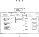
- Fig. 3 indicates the control system for the purge stocker 2.
- a stocker controller 30 is the top-level controller in the purge stocker 2 and communicates with a transport controller 32 that controls the transport apparatus 6, in particular, the running motor 33, the elevation motor 34, and the transfer device10, and also with a purge controller 36 that controls the MFCs 22.
- the stocker controller 30 also communicates with an outside controller 38 and so on, and assigns a shelf 14 for an unloading position for an incoming FOUP 16, when informed that the incoming FOUP 16 shall be entered in. Further, when the incoming FOUP 16 arrives at an entrance and dispatch port, not shown in the drawings, the stocker controller 30 instructs the transport controller 32 to unload the incoming FOUP 16 on the shelf 14 designated as the unloading position.
- the stocker controller 30 determines a shelf 14 as the next unloading position, in advance and in preparation for the occurrence of a next incoming FOUP 16 to be entered, when the above unloading job of the incoming FOUP 16 is completed. Namely, the stocker controller 30 assigns in advance one shelf 14 for the next unloading position, in preparation for the storage of the next incoming FOUP 16.
- the stocker controller 30 designates, to the transport controller 32, the shelf 14 where the FOUP 16 to be dispatched is stored and instructs it to load the FOUP 16 at the designated shelf 14 and to transport to the entrance and dispatch port.
- a port for both entrance and dispatch may be provided, or an entrance port and a separate dispatch port may be provided.
- the stocker controller 30 has a memory that stores a file such as a shelf file 31; the memory stores the status of each shelf 14 comprising: "empty”, “empty but assigned for an incoming or next incoming container", "storing a container”, “storing a container assigned to dispatch”, etc.
- a file such as a shelf file 31
- the memory stores the status of each shelf 14 comprising: "empty”, “empty but assigned for an incoming or next incoming container", "storing a container”, “storing a container assigned to dispatch”, etc.
- Physically one controller may form all of the controllers 30, 32, and 36, or each of the controllers 30, 32, and 36 may comprise plural computers.
- the purge controller 36 controls the MFC 22 to carry out storage purge (purge for maintaining the cleanliness in a FOUP 16) when it detects that a FOUP 16 was unloaded on a shelf 14, by a signal from a load sensor 21. Further, when the purge controller 36 is informed, by the stocker controller 30, that a shelf 14 is assigned for a next incoming FOUP 16, before the actual occurrence of the next incoming FOUP 16 (immediately after the completion of a preceding entrance job), in preparation for the entrance job of the next incoming FOUP 16, the purge controller 36 carries out nozzle purge (purge for cleaning a nozzle 20) in the assigned shelf 14 so that the nozzle 20 in the assigned shelf 14 is cleaned.
- storage purge purge for maintaining the cleanliness in a FOUP 16
- the purge controller 36 when the purge controller 36 is informed, through the transport controller 32 and the stocker controller 30, that the arm, the fork, or the like of the transfer device 10 is advancing towards the shelf 14 for unloading, or the similar event, the purge controller 36 carries out bottom purge (purge for cleaning the bottom portion of a FOUP 16 facing a nozzle 20) for cleaning the bottom portion (inlet portion of clean gas in the bottom) of the incoming FOUP 16.
- the bottom purge may be omitted.
- the purge controller 36 may carry out the storage purge according to an information, via the stocker controller 30 from the transport controller 32, that the entrance job of the incoming FOUP 16 to the shelf 14 has been completed, rather than carrying out the storage purge according to the signal from the load sensor 21.
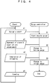
- Fig. 4 indicates the purge algorithm for a FOUP 16 according to the embodiment.
- the purge controller 36 starts the nozzle purge for the assigned shelf 14 (S1).
- the purge controller 36 changes the nozzle purge to the bottom purge (S2).
- the bottom purge may be omitted.
- the purge controller 36 may start the bottom purge.
- the purge controller 36 recognizes that the FOUP 16 has been unloaded on the shelf 14, by a signal from the load sensor 21, the transport controller 32, etc. (e3), the purge controller 36 carries out the storage purge (S3).
- the status of the shelf 14 returns to the empty status, and no further purge is necessary until it will be assigned for a next incoming FOUP.
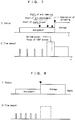
- Fig. 5 indicates a standard purge pattern.
- the purge controller 36 starts the nozzle purge for the assigned shelf 14.
- the nozzle purge is carried out intermittently; in other words, clean gas is repetitively discharged as pulses for a short duration from the nozzle 20.
- the solid line in Fig. 6 indicates the flow amount pattern of the clean gas according to the embodiment.
- the chain line in Fig. 6 indicates a constant flow amount pattern of the clean gas for the same total flow amount.
- the velocity of the clean gas is increased and the pressure around the nozzle 20 is fluctuated due to the on and off of the clean gas flow, and therefore, the nozzle is more efficiently cleaned than when the clean gas is discharged at a constant and small flow amount.
- the discharge duration and the discharge amount of the clean gas for one discharge pulse may be constant or not constant.
- the clean gas may be discharged for a relatively longer duration so that the nozzle 20 is cleaned and then, the clean gas may be repetitively discharged for relatively shorter duration for preventing the recontamination of the nozzle 20.
- the flow amount of the clean gas may be changed in such a way that, initially, at a relatively larger flow amount, the nozzle purge is performed and then the nozzle purge is performed at a relatively smaller flow amount.
- the start of the advancement of the arm, the fork, or the like of the transfer device 10, and also the start of lowering of the arm, the fork, or the like, indicate the presence of a FOUP 16 over the shelf 14. Therefore, at the time when the arm, the fork, or the like of the transfer device 10 starts to advance, or at the time when they start to lower, clean gas is discharged, for example continuously, at a relatively larger flow amount from the nozzle 20.
- This process is called bottom purge, and its flow amount pattern is indicated in Fig. 7 .
- the bottom purge may be omitted.
- the discharge of clean gas from the nozzle 20 may be made on and off so that pulsation of clean gas flow is applied to the input valve and its neighborhood.
- the purge controller 36 carries out the storage purge that replaces the atmosphere in the FOUP 16 by clean gas.
- the purge controller 36 starts the purge of the nozzle 20, and therefore, the purge is carried out for an enough long duration.
- the purge controller 36 starts the purge of the nozzle 20, and therefore, the purge is carried out for an enough long duration.
- the intermittent nozzle purge makes the nozzle cleaner, efficiently with a small total flow amount.
- Fig. 9 indicates a clean gas flow amount pattern for one group of shelves according to a modification where plural shelves 14 are controlled as one group. This modification is suitable for a case where a common MFC 22 is provided for a column or a row of shelves as a unit.
- the purge controller 36 starts the nozzle purge in all shelves 14 within the group. Further, when the transport apparatus 6 starts the transfer of the FOUP 16 to the assigned shelf 14 for unloading, the purge controller 36 increases the flow amount of the clean gas so that the bottom portion of the FOUP 16 is purged.
- the stocker controller 30 assigns the empty shelf for a next incoming FOUP 16.
- the storage purge is carried out for the unloaded FOUP 16 so that the atmosphere in the FOUP 16 is substituted by the clean gas.
- the purge controller 36 restarts the nozzle purge.
- Fig. 10 indicates an embodiment where an overhead transport system is used as the storage system.
- a plurality of overhead transport vehicles 42 run, and there are provided a plurality of buffers 44 for storing temporarily FOUPs, along the running rail 40.
- the buffers 44 may have one or plural shelves 45 per buffer.
- a system controller 46 controls the entire overhead transport system, communicates with an outside controller, and receives transport requests of FOUPs from the outside controller.
- the buffer 44 is provided with a nozzle 20 in each shelf 45, and a purge controller 48 controls an MFC 22 so as to regulate the supply of clean gas to the nozzle 20.
- the system controller 46 assigns an empty buffer 44 for temporarily storing a FOUP in advance, when it is required to transport a FOUP from an outside controller, or spontaneously without waiting for the request from the outside controller. Then, the system controller 46 instructs the purge controller 48 in the assigned empty buffer 44 to start the nozzle purge. Further, if the entrance of a transfer device of an overhead transport vehicle 42 over the shelf 45 is detectable, the purge controller 48 carries out the bottom purge.
- purge stocker 4 wall 5 door 6 transport apparatus 7 running vehicle 8 mast 9 carriage 10 transfer device 11 rail 14 shelf 16 FOUP (container) 17 opening 18 shelf support 19 pin 20 purge nozzle 21 load sensor 22 MFC 23 pipe 30 stocker controller 31 shelf file 32 transport controller 33 running motor 34 elevation motor 36 purge controller 38 outside controller 40 running rail 42 overhead transport vehicle 44 buffer 45 shelf 46 system controller 48 purge controller
Landscapes
- Engineering & Computer Science (AREA)
- Physics & Mathematics (AREA)
- Condensed Matter Physics & Semiconductors (AREA)
- General Physics & Mathematics (AREA)
- Manufacturing & Machinery (AREA)
- Computer Hardware Design (AREA)
- Microelectronics & Electronic Packaging (AREA)
- Power Engineering (AREA)
- Mechanical Engineering (AREA)
- Container, Conveyance, Adherence, Positioning, Of Wafer (AREA)
- Warehouses Or Storage Devices (AREA)
Abstract
Description
- The present invention relates to a storage system, such as a purge stocker, and a purge method in the storage system.
- Purge stockers have shelves and nozzles provided in the shelves; the nozzles are configured to be made in contact with valves in the bottoms of containers, such as FOUPs, stored on the shelves, and are configured to supply clean gas, such as nitrogen gas or clean dry air, into the containers.
- The present applicant found the contamination of nozzles in the shelves has the risk to causes the contamination of articles, such as semiconductor wafers, in the containers and has proposed to carry out cleaning of the nozzles (to blow away particles on the nozzles) by supplying a small amount of clean gas to the nozzles in empty shelves without the containers (Patent Document 1:
JP4692584B JP5557061B - Regarding to commence the nozzle cleaning when the transport apparatus has started to move, the present inventors have found cases where a container was connected with a not fully cleaned nozzle, because the transport apparatus had arrived at the shelf assigned for the unloading position before the completion of cleaning, and cases where the transport apparatus had to wait for the completion of the cleaning before the transfer of a container with the shelf.
-
- Patent Document 1:
JP4692584B - Patent Document 2:
JP5557061B - The object of the present invention is to provide a storage system and a purge method in the storage system, capable of fully cleaning nozzles before transferring containers to and on the corresponding shelves, with a reduced amount of clean gas consumption, and without phenomena such as delaying the transfer by the transport apparatus for waiting for the completion of the nozzle cleaning.
- A storage system according to the present invention comprises: a plurality of shelves, respectively provided with at least one nozzle for supplying clean gas into containers; a plurality of flow amount controlling devices, respectively controlling supply amount of said clean gas to said at least one nozzle; at least one transport apparatus transferring said containers to and from said shelves; and a controller controlling said at least one transport apparatus and said flow amount controlling devices.
- According to the present invention, said controller is configured and programmed
to make an assignment of at least one shelf in preparation for storing an incoming container and before the occurrence of said incoming container, and
to control one of said flow amount controlling devices to supply said clean gas to said at least one nozzle in said at least one shelf, based upon said assignment. - A purge method according to the present invention uses a storage system comprising: a plurality of shelves, respectively provided with at least one nozzle for supplying clean gas into containers; a plurality of flow amount controlling devices, respectively controlling supply amount of said clean gas to said at least one nozzle; at least one transport apparatus transferring said containers to and from said shelves; and a controller controlling said at least one transport apparatus and said flow amount controlling devices.
- The method according to the present invention comprises: making an assignment of at least one shelf in preparation for storing an incoming container and before the occurrence of said incoming container, by said controller; and supplying said clean gas to said at least one nozzle in said at least one shelf, based upon said assignment.
- According to the present invention, before the occurrence of the incoming container, in other words, before the incoming container arrives at the present purge system, said at least one shelf is assigned for storing the incoming container and the cleaning of the nozzle in the assigned shelf is started. Therefore, when the incoming container will arrive at the shelf, the nozzle will be fully cleaned. In addition, an enough time duration is present for the nozzle cleaning, and therefore, there arises no delay of transfer motion by the transport apparatus for unloading the incoming container to the shelf, due to waiting for the completion of the nozzle cleaning.
- Preferably, said storage system is a purge stocker and is further provided with an entrance and dispatch port, said at least one transport apparatus transports said incoming container between said entrance and dispatch port and said shelves, and said controller is further configured and programmed to make said assignment of said at least one shelf in advance, before said incoming container will arrive at said entrance and dispatch port. In this case, the assignment of the shelf, and the nozzle cleaning are commenced before the incoming container will arrive; and therefore, the nozzle is fully cleaned before the incoming container will arrive at the shelf.
- Preferably, said controller is further configured and programmed to control said one of said flow amount controlling devices to intermittently supply said clean gas to said at least one nozzle in said at least one shelf. In this configuration, even if the incoming container is not unloaded on the assigned shelf for a long time, the nozzle is kept clean with a small consumption amount of clean gas. Namely, even if the incoming container is not unloaded for a long time, the nozzle is kept cleaner than a case where no clean gas is supplied at all. In addition, the consumption amount of clean gas is smaller than a case where the clean gas is supplied continuously.
- Particularly preferably, said at least one transport apparatus is provided with a transfer device entering into and unloading said incoming container on said shelves, and said controller is further configured and programmed to control said one of said flow amount controlling devices to supply a larger flow amount of said clean gas to said at least one nozzle, from when said transfer device starts advancement towards said at least one shelf and until completing unloading of said incoming container, than an amount before said transfer device starts advancement. Then, not only the nozzle but also the bottom (abutting the nozzle) of the incoming container held by the transfer device are made clean .
-
- [
Fig. 1 ] A vertical cross-sectional view of a purge stocker (storage system) according to an embodiment. - [
Fig. 2 ] A plan view of the shelves of the purge stocker. - [
Fig. 3 ] A block diagram of the control system of the purge stocker according to the embodiment. - [
Fig. 4 ] A flowchart of the purge algorithm according to the embodiment. - [
Fig. 5 ] A diagram where 1) indicates the status of a shelf and 2) indicates the flow amount of clean gas, according to the embodiment. - [
Fig. 6 ] A diagram indicating the flow amount pattern of clean gas during nozzle purge (purge for cleaning a nozzle) according to the embodiment. - [
Fig. 7 ] A diagram where 1) indicates the status of the arm of the transport apparatus and 2) indicates the flow amount of clean gas, according to the embodiment. - [
Fig. 8 ] A diagram indicating the flow amount of clean gas for storage purge (purge for maintaining the cleanliness in containers) according to the embodiment, where 1) indicates the status of a shelf and 2) indicates the flow amount of clean gas. - [
Fig. 9 ] A diagram indicating the flow amount pattern of clean gas according to a modification. - [
Fig. 10 ] A plan view of the layout of a storage system (overhead transport system) according to a second embodiment. - The best and other embodiments and a modification for carrying out the present invention will be described. The scope of the present invention shall be construed based upon the claims with reference to the description and well-known art in the field, as the ordinary persons in the field understand.
-
Figs. 1-8 indicate apurge stocker 2 according to an embodiment. Thepurge stocker 2 is provided within a clean room and so on, and stores containers for semiconductor wafers, reticles, and so on. Thepurge stocker 2 is shut off from outside atmosphere by awall 4, and thewall 4 is provided with adoor 5. - As shown in
Fig. 1 , thepurge stocker 2 is provided with atransport apparatus 6 and a plurality ofshelves 14; thetransport apparatus 6 is, for example, a stacker crane, but the species of thetransport apparatus 6 is arbitrary. Thetransport apparatus 6 has a runningvehicle 7 that runs on arail 11 and supports amast 8, and a carriage 9 elevates and lowers along themast 8. The carriage 9 in thetransport apparatus 6 is provided with atransfer device 10, such as a SCARA arm, a sliding fork, and so on, for transferring acontainer 16 between ashelf 14. In the specification,plural shelves 14 aligned along a vertical direction are called a column, andplural shelves 14 aligned horizontally with the same height are called a row. - The
container 16 according to the embodiment is a FOUP which stores semiconductor wafers and is provided with a valve in the bottom portion that receives clean gas from a nozzle in theshelf 14, and thus, the inside of the container is kept clean. The species of thecontainer 16 is arbitrary, as long as thecontainer 16 is configured to be purged by clean gas blown into from a nozzle of ashelf 14. -
Fig. 2 indicates theshelves 14. Theshelf 14 is provided with ashelf support 18 having anopening 17; thetransport apparatus 10 enters the arm, fork, or the like, into theopening 17 and transfers aFOUP 16 between theshelf 14. Each of theshelves 14 has threepins 19 and thesepins 19 are coupled with grooves in the bottom ofFOUP 16 and position theFOUP 16. Around the opening 17, a pair of or onepurge nozzle 20 is provided and thepurge nozzle 20 supplies clean gas such as nitrogen or clean dry air into a FOUP 16 supported on theshelf support 18. Theshelf support 18 is further provided with aload sensor 21; theload sensor 21 detects whether aFOUP 16 is present or absent on thecorresponding shelf 14. An MFC 22 (mass flow controller, an example of flow amount controlling device) supplies clean gas through apipe 23 to the purge nozzle 20 (hereinafter, may be simply referred to as "nozzle 20" or "nozzle"). Theshelf 14 may be provided further with an exhaust nozzle for evacuating the atmosphere in aFOUP 16, and so on in addition to thepurge nozzle 20. - According to the embodiment, an
MFC 22 is provided for eachshelf 14 so that the flow amount of clean gas from anozzle 20 is controlled for eachshelf 14. However, acommon MFC 22 for a column or a row may be provided so that the total flow amount of clean gas for the column or the row is controlled. -
Fig. 3 indicates the control system for thepurge stocker 2. Astocker controller 30 is the top-level controller in thepurge stocker 2 and communicates with atransport controller 32 that controls thetransport apparatus 6, in particular, the runningmotor 33, theelevation motor 34, and the transfer device10, and also with apurge controller 36 that controls theMFCs 22. Thestocker controller 30 also communicates with anoutside controller 38 and so on, and assigns ashelf 14 for an unloading position for anincoming FOUP 16, when informed that theincoming FOUP 16 shall be entered in. Further, when theincoming FOUP 16 arrives at an entrance and dispatch port, not shown in the drawings, thestocker controller 30 instructs thetransport controller 32 to unload theincoming FOUP 16 on theshelf 14 designated as the unloading position. In addition, thestocker controller 30 determines ashelf 14 as the next unloading position, in advance and in preparation for the occurrence of a nextincoming FOUP 16 to be entered, when the above unloading job of theincoming FOUP 16 is completed. Namely, thestocker controller 30 assigns in advance oneshelf 14 for the next unloading position, in preparation for the storage of the nextincoming FOUP 16. On the other hand, when instructed by theoutside controller 38 or the like, to dispatch aFOUP 16, thestocker controller 30 designates, to thetransport controller 32, theshelf 14 where theFOUP 16 to be dispatched is stored and instructs it to load theFOUP 16 at the designatedshelf 14 and to transport to the entrance and dispatch port. A port for both entrance and dispatch may be provided, or an entrance port and a separate dispatch port may be provided. - The
stocker controller 30 has a memory that stores a file such as ashelf file 31; the memory stores the status of eachshelf 14 comprising: "empty", "empty but assigned for an incoming or next incoming container", "storing a container", "storing a container assigned to dispatch", etc. Physically one controller may form all of thecontrollers controllers - The
purge controller 36 controls theMFC 22 to carry out storage purge (purge for maintaining the cleanliness in a FOUP 16) when it detects that aFOUP 16 was unloaded on ashelf 14, by a signal from aload sensor 21. Further, when thepurge controller 36 is informed, by thestocker controller 30, that ashelf 14 is assigned for a nextincoming FOUP 16, before the actual occurrence of the next incoming FOUP 16 (immediately after the completion of a preceding entrance job), in preparation for the entrance job of the nextincoming FOUP 16, thepurge controller 36 carries out nozzle purge (purge for cleaning a nozzle 20) in the assignedshelf 14 so that thenozzle 20 in the assignedshelf 14 is cleaned. In addition, when thepurge controller 36 is informed, through thetransport controller 32 and thestocker controller 30, that the arm, the fork, or the like of thetransfer device 10 is advancing towards theshelf 14 for unloading, or the similar event, thepurge controller 36 carries out bottom purge (purge for cleaning the bottom portion of aFOUP 16 facing a nozzle 20) for cleaning the bottom portion (inlet portion of clean gas in the bottom) of theincoming FOUP 16. The bottom purge may be omitted. - The
purge controller 36 may carry out the storage purge according to an information, via thestocker controller 30 from thetransport controller 32, that the entrance job of theincoming FOUP 16 to theshelf 14 has been completed, rather than carrying out the storage purge according to the signal from theload sensor 21. -
Fig. 4 indicates the purge algorithm for aFOUP 16 according to the embodiment. When oneshelf 14 is assigned for a next incoming FOUP 16 (e1), thepurge controller 36 starts the nozzle purge for the assigned shelf 14 (S1). Subsequently, when thetransport apparatus 6 comes near to theshelf 14 and further when the arm, the fork, or the like of thetransfer device 10 starts to advance towards the shelf 14 (e2), thepurge controller 36 changes the nozzle purge to the bottom purge (S2). However, the bottom purge may be omitted. Alternatively, when the arm, fork, or the like starts lowering (unloading), thepurge controller 36 may start the bottom purge. Then, when thepurge controller 36 recognizes that theFOUP 16 has been unloaded on theshelf 14, by a signal from theload sensor 21, thetransport controller 32, etc. (e3), thepurge controller 36 carries out the storage purge (S3). In addition, when aFOUP 16 is loaded from a shelf 14 (e4), the status of theshelf 14 returns to the empty status, and no further purge is necessary until it will be assigned for a next incoming FOUP. -
Fig. 5 indicates a standard purge pattern. When oneshelf 14 is assigned for a nextincoming FOUP 16, thepurge controller 36 starts the nozzle purge for the assignedshelf 14. Preferably, the nozzle purge is carried out intermittently; in other words, clean gas is repetitively discharged as pulses for a short duration from thenozzle 20. The solid line inFig. 6 indicates the flow amount pattern of the clean gas according to the embodiment. On the other hand, the chain line inFig. 6 indicates a constant flow amount pattern of the clean gas for the same total flow amount. When the clean gas is discharged at a larger flow amount for shorter duration from thenozzle 20, the velocity of the clean gas is increased and the pressure around thenozzle 20 is fluctuated due to the on and off of the clean gas flow, and therefore, the nozzle is more efficiently cleaned than when the clean gas is discharged at a constant and small flow amount. - When the clean gas is discharged intermittently during the nozzle purge, the discharge duration and the discharge amount of the clean gas for one discharge pulse may be constant or not constant. For example, initially, the clean gas may be discharged for a relatively longer duration so that the
nozzle 20 is cleaned and then, the clean gas may be repetitively discharged for relatively shorter duration for preventing the recontamination of thenozzle 20. Further, the flow amount of the clean gas may be changed in such a way that, initially, at a relatively larger flow amount, the nozzle purge is performed and then the nozzle purge is performed at a relatively smaller flow amount. - The start of the advancement of the arm, the fork, or the like of the
transfer device 10, and also the start of lowering of the arm, the fork, or the like, indicate the presence of aFOUP 16 over theshelf 14. Therefore, at the time when the arm, the fork, or the like of thetransfer device 10 starts to advance, or at the time when they start to lower, clean gas is discharged, for example continuously, at a relatively larger flow amount from thenozzle 20. This makes the bottom of theFOUP 16 clean; in particular, an input valve for clean gas and its neighborhood are made clean. This process is called bottom purge, and its flow amount pattern is indicated inFig. 7 . By the way, as shown inFig. 8 , the bottom purge may be omitted. Further, during the bottom purge, the discharge of clean gas from thenozzle 20 may be made on and off so that pulsation of clean gas flow is applied to the input valve and its neighborhood. When theload sensor 21 detects that theFOUP 16 is unloaded on theshelf 14, thepurge controller 36 carries out the storage purge that replaces the atmosphere in theFOUP 16 by clean gas. - According to the embodiment, when a
shelf 14 is assigned for anincoming FOUP 16 in the future, thepurge controller 36 starts the purge of thenozzle 20, and therefore, the purge is carried out for an enough long duration. As a result, there is no risk that aFOUP 16 is unloaded over a not fully purged nozzle nor that the unloading is postponed until the completion of the purge. Further, the intermittent nozzle purge makes the nozzle cleaner, efficiently with a small total flow amount. -
Fig. 9 indicates a clean gas flow amount pattern for one group of shelves according to a modification whereplural shelves 14 are controlled as one group. This modification is suitable for a case where acommon MFC 22 is provided for a column or a row of shelves as a unit. When thestocker controller 30 assigns oneshelf 14 within one group for a nextincoming FOUP 16, thepurge controller 36 starts the nozzle purge in allshelves 14 within the group. Further, when thetransport apparatus 6 starts the transfer of theFOUP 16 to the assignedshelf 14 for unloading, thepurge controller 36 increases the flow amount of the clean gas so that the bottom portion of theFOUP 16 is purged. When the unloading of theFOUP 16 on theshelf 14 is completed and further when the group has at least one empty shelf, thestocker controller 30 assigns the empty shelf for a nextincoming FOUP 16. In addition, the storage purge is carried out for the unloadedFOUP 16 so that the atmosphere in theFOUP 16 is substituted by the clean gas. After the completion of the storage purge, thepurge controller 36 restarts the nozzle purge. By the way, when there is no empty shelf within the group (when all shelves in the group are occupied), the stocker controller assigns an empty shelf within another group for the nextincoming FOUP 16. Further, thepurge controller 36 starts the nozzle purge in allshelves 14 within said another group. -
Fig. 10 indicates an embodiment where an overhead transport system is used as the storage system. Along a runningrail 40, a plurality ofoverhead transport vehicles 42 run, and there are provided a plurality ofbuffers 44 for storing temporarily FOUPs, along the runningrail 40. By the way, thebuffers 44 may have one orplural shelves 45 per buffer. Further, asystem controller 46 controls the entire overhead transport system, communicates with an outside controller, and receives transport requests of FOUPs from the outside controller. In addition, thebuffer 44 is provided with anozzle 20 in eachshelf 45, and apurge controller 48 controls anMFC 22 so as to regulate the supply of clean gas to thenozzle 20. - The
system controller 46 assigns anempty buffer 44 for temporarily storing a FOUP in advance, when it is required to transport a FOUP from an outside controller, or spontaneously without waiting for the request from the outside controller. Then, thesystem controller 46 instructs thepurge controller 48 in the assignedempty buffer 44 to start the nozzle purge. Further, if the entrance of a transfer device of anoverhead transport vehicle 42 over theshelf 45 is detectable, thepurge controller 48 carries out the bottom purge. -
2 purge stocker 4 wall 5 door 6 transport apparatus 7 running vehicle 8 mast 9 carriage 10 transfer device 11 rail 14 shelf 16 FOUP (container) 17 opening 18 shelf support 19 pin 20 purge nozzle 21 load sensor 22 MFC 23 pipe 30 stocker controller 31 shelf file 32 transport controller 33 running motor 34 elevation motor 36 purge controller 38 outside controller 40 running rail 42 overhead transport vehicle 44 buffer 45 shelf 46 system controller 48 purge controller
Claims (5)
- A storage system comprising: a plurality of shelves (14), respectively provided with at least one nozzle (20) for supplying clean gas into containers (16); a plurality of flow amount controlling devices (22), respectively controlling supply amount of said clean gas to said at least one nozzle (20); at least one transport apparatus (6) transferring said containers (16) to and from said shelves (14); and a controller (30,32,36) controlling said at least one transport apparatus (6) and said flow amount controlling devices (22),
wherein said controller (30,32,36) is configured and programmedto make an assignment of at least one shelf (14) in preparation for storing an incoming container (16) and before the occurrence of said incoming container (16), andto control one of said flow amount controlling devices (22) to supply said clean gas to said at least one nozzle (20) in said at least one shelf (14), based upon said assignment. - The storage system according to claim 1, wherein said storage system is a purge stocker (2) and is further provided with an entrance and dispatch port,
wherein said at least one transport apparatus (6) transports said containers (16) between said entrance and dispatch port and said shelves (14), and
wherein said controller (30) is further configured and programmed to make said assignment of said at least one shelf (14) in advance, before said incoming container (16) arrives at said entrance and dispatch port. - The storage system according to claim 1 or 2, wherein said controller (36) is further configured and programmed to control said one of said flow amount controlling devices (22) to intermittently supply said clean gas to said at least one nozzle (20) in said at least one shelf (14).
- The storage system according to one of claims 1 to 3, wherein said at least one transport apparatus (6) is provided with a transfer device (10) entering into and unloading said incoming container (16) on said shelves (14), and
wherein said controller (36) is further configured and programmed to control said one of said flow amount controlling devices (22) to supply a larger flow amount of said clean gas to said at least one nozzle (20), from when said transfer device (6) starts advancement towards said at least one shelf (14) and until completing unloading of said incoming container (16), than an amount before said transfer device (6) starts advancement. - A purge method in a storage system comprising: a plurality of shelves (14), respectively provided with at least one nozzle (20) for supplying clean gas into containers (16); a plurality of flow amount controlling devices (22), respectively controlling supply amount of said clean gas to said at least one nozzle (20); at least one transport apparatus (6) transferring said containers (16) to and from said shelves (14); and a controller (30,32,36) controlling said at least one transport apparatus (6) and said flow amount controlling devices (22),
said method comprising: making an assignment of at least one shelf (14) in preparation for storing an incoming container (16) and before the occurrence of said incoming container (16), by said controller (30); and
supplying said clean gas to said at least one nozzle (20) in said at least one shelf (14), based upon said assignment.
Applications Claiming Priority (2)
| Application Number | Priority Date | Filing Date | Title |
|---|---|---|---|
| JP2017172888 | 2017-09-08 | ||
| PCT/JP2018/027043 WO2019049518A1 (en) | 2017-09-08 | 2018-07-19 | Storage system and purge method in storage system |
Publications (3)
| Publication Number | Publication Date |
|---|---|
| EP3680930A1 true EP3680930A1 (en) | 2020-07-15 |
| EP3680930A4 EP3680930A4 (en) | 2021-06-02 |
| EP3680930B1 EP3680930B1 (en) | 2023-12-27 |
Family
ID=65633756
Family Applications (1)
| Application Number | Title | Priority Date | Filing Date |
|---|---|---|---|
| EP18854967.9A Active EP3680930B1 (en) | 2017-09-08 | 2018-07-19 | Storage system and purge method in storage system |
Country Status (9)
| Country | Link |
|---|---|
| US (1) | US11608229B2 (en) |
| EP (1) | EP3680930B1 (en) |
| JP (1) | JP6813097B2 (en) |
| KR (1) | KR102391970B1 (en) |
| CN (1) | CN111052338B (en) |
| IL (1) | IL272426B (en) |
| SG (1) | SG11202001780UA (en) |
| TW (1) | TWI749256B (en) |
| WO (1) | WO2019049518A1 (en) |
Families Citing this family (5)
| Publication number | Priority date | Publication date | Assignee | Title |
|---|---|---|---|---|
| CN112385030A (en) * | 2018-07-20 | 2021-02-19 | 村田机械株式会社 | Storage rack and setting method thereof |
| CN110745449A (en) * | 2019-10-18 | 2020-02-04 | 艾信智慧医疗科技发展(苏州)有限公司 | Control method of intelligent container and intelligent container |
| JP7188615B2 (en) * | 2019-11-05 | 2022-12-13 | 村田機械株式会社 | carrier system |
| KR102663006B1 (en) * | 2020-09-07 | 2024-05-02 | 세메스 주식회사 | Apparatus for storing carriers |
| CN117461122A (en) * | 2021-10-01 | 2024-01-26 | 村田机械株式会社 | Purifying device |
Family Cites Families (23)
| Publication number | Priority date | Publication date | Assignee | Title |
|---|---|---|---|---|
| JPH07130831A (en) * | 1993-10-28 | 1995-05-19 | Nippon Steel Corp | Housing/conveying device for semiconductor wafer |
| TW491802B (en) | 2001-05-21 | 2002-06-21 | Taiwan Semiconductor Mfg | Automated material handling method basing on adaptability control |
| US6899145B2 (en) * | 2003-03-20 | 2005-05-31 | Asm America, Inc. | Front opening unified pod |
| JP4027837B2 (en) * | 2003-04-28 | 2007-12-26 | Tdk株式会社 | Purge apparatus and purge method |
| JP4012190B2 (en) * | 2004-10-26 | 2007-11-21 | Tdk株式会社 | Closed container lid opening and closing system and opening and closing method |
| JP4692584B2 (en) * | 2008-07-03 | 2011-06-01 | 村田機械株式会社 | Purge device |
| JP5381054B2 (en) * | 2008-12-02 | 2014-01-08 | シンフォニアテクノロジー株式会社 | Load port |
| JP5236518B2 (en) * | 2009-02-03 | 2013-07-17 | 株式会社ダン・タクマ | Storage system and storage method |
| JP2012094822A (en) * | 2010-09-30 | 2012-05-17 | Shibaura Mechatronics Corp | Hermetic type container and semiconductor manufacturing device |
| JP5887719B2 (en) * | 2011-05-31 | 2016-03-16 | シンフォニアテクノロジー株式会社 | Purge device, load port, bottom purge nozzle body, bottom purge unit |
| JP5366030B2 (en) * | 2011-09-22 | 2013-12-11 | 村田機械株式会社 | Automated warehouse for clean rooms |
| KR101147192B1 (en) * | 2011-11-11 | 2012-05-25 | 주식회사 엘에스테크 | Apparatus for purge native oxide of wafer |
| JP5598728B2 (en) | 2011-12-22 | 2014-10-01 | 株式会社ダイフク | Inert gas injection device |
| JP5557061B2 (en) | 2012-01-04 | 2014-07-23 | 株式会社ダイフク | Goods storage facility |
| JP5716968B2 (en) * | 2012-01-04 | 2015-05-13 | 株式会社ダイフク | Goods storage facility |
| JP5884780B2 (en) * | 2013-06-26 | 2016-03-15 | 株式会社ダイフク | Storage facilities |
| JP5884779B2 (en) * | 2013-06-26 | 2016-03-15 | 株式会社ダイフク | Goods storage facility |
| US10325794B2 (en) * | 2014-04-28 | 2019-06-18 | Murata Machinery, Ltd. | Purge device and purge method |
| JP2016054240A (en) * | 2014-09-04 | 2016-04-14 | 村田機械株式会社 | Stocker |
| JP6459682B2 (en) * | 2015-03-20 | 2019-01-30 | Tdk株式会社 | Gas purge device, load port device and gas purge method |
| JP2016218603A (en) * | 2015-05-18 | 2016-12-22 | 村田機械株式会社 | Flow control device, purge device, and purge stocker |
| CN107922114B (en) * | 2015-08-10 | 2020-01-24 | 村田机械株式会社 | Cleaning device, cleaning stocker, and cleaning method |
| CN107924856B (en) * | 2015-08-25 | 2021-05-28 | 村田机械株式会社 | Blowing-out device, blowing-out stocker, and blowing-out method |
-
2018
- 2018-07-19 JP JP2019540805A patent/JP6813097B2/en active Active
- 2018-07-19 KR KR1020207009152A patent/KR102391970B1/en active IP Right Grant
- 2018-07-19 US US16/642,084 patent/US11608229B2/en active Active
- 2018-07-19 EP EP18854967.9A patent/EP3680930B1/en active Active
- 2018-07-19 SG SG11202001780UA patent/SG11202001780UA/en unknown
- 2018-07-19 WO PCT/JP2018/027043 patent/WO2019049518A1/en unknown
- 2018-07-19 CN CN201880055618.4A patent/CN111052338B/en active Active
- 2018-09-03 TW TW107130851A patent/TWI749256B/en active
-
2020
- 2020-02-02 IL IL272426A patent/IL272426B/en active IP Right Grant
Also Published As
| Publication number | Publication date |
|---|---|
| EP3680930B1 (en) | 2023-12-27 |
| IL272426B (en) | 2020-09-30 |
| KR102391970B1 (en) | 2022-04-28 |
| KR20200047639A (en) | 2020-05-07 |
| JPWO2019049518A1 (en) | 2020-08-13 |
| IL272426A (en) | 2020-03-31 |
| TWI749256B (en) | 2021-12-11 |
| SG11202001780UA (en) | 2020-03-30 |
| WO2019049518A1 (en) | 2019-03-14 |
| US20200180864A1 (en) | 2020-06-11 |
| TW201936465A (en) | 2019-09-16 |
| CN111052338A (en) | 2020-04-21 |
| CN111052338B (en) | 2023-06-30 |
| US11608229B2 (en) | 2023-03-21 |
| JP6813097B2 (en) | 2021-01-13 |
| EP3680930A4 (en) | 2021-06-02 |
Similar Documents
| Publication | Publication Date | Title |
|---|---|---|
| EP3680930B1 (en) | Storage system and purge method in storage system | |
| US9701431B2 (en) | Load port device, transport system, and container carrying out method | |
| EP3200221B1 (en) | Purging device and purging method | |
| CN107924857B (en) | Storage apparatus and storage method | |
| TWI647017B (en) | Purification device, purification system, purification method and control method of purification system | |
| CN107534004B (en) | Cleaning stocker and cleaning method | |
| JP2968742B2 (en) | Automatic storage shelf and automatic storage method | |
| US6447217B1 (en) | Substrate transfer device and operating method thereof | |
| JP6152843B2 (en) | Buffer system and article buffering method | |
| TW201722813A (en) | Transport system and transport method | |
| JP4657528B2 (en) | Processing system and processing method |
Legal Events
| Date | Code | Title | Description |
|---|---|---|---|
| STAA | Information on the status of an ep patent application or granted ep patent |
Free format text: STATUS: THE INTERNATIONAL PUBLICATION HAS BEEN MADE |
|
| PUAI | Public reference made under article 153(3) epc to a published international application that has entered the european phase |
Free format text: ORIGINAL CODE: 0009012 |
|
| STAA | Information on the status of an ep patent application or granted ep patent |
Free format text: STATUS: REQUEST FOR EXAMINATION WAS MADE |
|
| 17P | Request for examination filed |
Effective date: 20200403 |
|
| AK | Designated contracting states |
Kind code of ref document: A1 Designated state(s): AL AT BE BG CH CY CZ DE DK EE ES FI FR GB GR HR HU IE IS IT LI LT LU LV MC MK MT NL NO PL PT RO RS SE SI SK SM TR |
|
| AX | Request for extension of the european patent |
Extension state: BA ME |
|
| DAV | Request for validation of the european patent (deleted) | ||
| DAX | Request for extension of the european patent (deleted) | ||
| A4 | Supplementary search report drawn up and despatched |
Effective date: 20210430 |
|
| RIC1 | Information provided on ipc code assigned before grant |
Ipc: H01L 21/677 20060101AFI20210423BHEP Ipc: B65G 1/00 20060101ALI20210423BHEP Ipc: B65G 1/137 20060101ALI20210423BHEP Ipc: H01L 21/673 20060101ALI20210423BHEP Ipc: B65G 1/02 20060101ALI20210423BHEP |
|
| STAA | Information on the status of an ep patent application or granted ep patent |
Free format text: STATUS: EXAMINATION IS IN PROGRESS |
|
| 17Q | First examination report despatched |
Effective date: 20221102 |
|
| GRAP | Despatch of communication of intention to grant a patent |
Free format text: ORIGINAL CODE: EPIDOSNIGR1 |
|
| STAA | Information on the status of an ep patent application or granted ep patent |
Free format text: STATUS: GRANT OF PATENT IS INTENDED |
|
| INTG | Intention to grant announced |
Effective date: 20230710 |
|
| RIN1 | Information on inventor provided before grant (corrected) |
Inventor name: YAMAJI, TAKASHI Inventor name: TSUBAKI, TATSUO |
|
| GRAS | Grant fee paid |
Free format text: ORIGINAL CODE: EPIDOSNIGR3 |
|
| GRAA | (expected) grant |
Free format text: ORIGINAL CODE: 0009210 |
|
| STAA | Information on the status of an ep patent application or granted ep patent |
Free format text: STATUS: THE PATENT HAS BEEN GRANTED |
|
| AK | Designated contracting states |
Kind code of ref document: B1 Designated state(s): AL AT BE BG CH CY CZ DE DK EE ES FI FR GB GR HR HU IE IS IT LI LT LU LV MC MK MT NL NO PL PT RO RS SE SI SK SM TR |
|
| REG | Reference to a national code |
Ref country code: GB Ref legal event code: FG4D |
|
| REG | Reference to a national code |
Ref country code: CH Ref legal event code: EP |
|
| REG | Reference to a national code |
Ref country code: DE Ref legal event code: R096 Ref document number: 602018063367 Country of ref document: DE |
|
| REG | Reference to a national code |
Ref country code: IE Ref legal event code: FG4D |
|
| PG25 | Lapsed in a contracting state [announced via postgrant information from national office to epo] |
Ref country code: GR Free format text: LAPSE BECAUSE OF FAILURE TO SUBMIT A TRANSLATION OF THE DESCRIPTION OR TO PAY THE FEE WITHIN THE PRESCRIBED TIME-LIMIT Effective date: 20240328 |
|
| REG | Reference to a national code |
Ref country code: LT Ref legal event code: MG9D |
|
| PG25 | Lapsed in a contracting state [announced via postgrant information from national office to epo] |
Ref country code: LT Free format text: LAPSE BECAUSE OF FAILURE TO SUBMIT A TRANSLATION OF THE DESCRIPTION OR TO PAY THE FEE WITHIN THE PRESCRIBED TIME-LIMIT Effective date: 20231227 |
|
| PG25 | Lapsed in a contracting state [announced via postgrant information from national office to epo] |
Ref country code: ES Free format text: LAPSE BECAUSE OF FAILURE TO SUBMIT A TRANSLATION OF THE DESCRIPTION OR TO PAY THE FEE WITHIN THE PRESCRIBED TIME-LIMIT Effective date: 20231227 |
|
| PG25 | Lapsed in a contracting state [announced via postgrant information from national office to epo] |
Ref country code: LT Free format text: LAPSE BECAUSE OF FAILURE TO SUBMIT A TRANSLATION OF THE DESCRIPTION OR TO PAY THE FEE WITHIN THE PRESCRIBED TIME-LIMIT Effective date: 20231227 Ref country code: GR Free format text: LAPSE BECAUSE OF FAILURE TO SUBMIT A TRANSLATION OF THE DESCRIPTION OR TO PAY THE FEE WITHIN THE PRESCRIBED TIME-LIMIT Effective date: 20240328 Ref country code: FI Free format text: LAPSE BECAUSE OF FAILURE TO SUBMIT A TRANSLATION OF THE DESCRIPTION OR TO PAY THE FEE WITHIN THE PRESCRIBED TIME-LIMIT Effective date: 20231227 Ref country code: ES Free format text: LAPSE BECAUSE OF FAILURE TO SUBMIT A TRANSLATION OF THE DESCRIPTION OR TO PAY THE FEE WITHIN THE PRESCRIBED TIME-LIMIT Effective date: 20231227 Ref country code: BG Free format text: LAPSE BECAUSE OF FAILURE TO SUBMIT A TRANSLATION OF THE DESCRIPTION OR TO PAY THE FEE WITHIN THE PRESCRIBED TIME-LIMIT Effective date: 20240327 |
|
| REG | Reference to a national code |
Ref country code: NL Ref legal event code: MP Effective date: 20231227 |
|
| REG | Reference to a national code |
Ref country code: AT Ref legal event code: MK05 Ref document number: 1645352 Country of ref document: AT Kind code of ref document: T Effective date: 20231227 |
|
| PG25 | Lapsed in a contracting state [announced via postgrant information from national office to epo] |
Ref country code: NL Free format text: LAPSE BECAUSE OF FAILURE TO SUBMIT A TRANSLATION OF THE DESCRIPTION OR TO PAY THE FEE WITHIN THE PRESCRIBED TIME-LIMIT Effective date: 20231227 |