EP3680655A1 - High-frequency-power-source uv lamp monitor, and total organic carbon meter in which same is used - Google Patents
High-frequency-power-source uv lamp monitor, and total organic carbon meter in which same is used Download PDFInfo
- Publication number
- EP3680655A1 EP3680655A1 EP18850855.0A EP18850855A EP3680655A1 EP 3680655 A1 EP3680655 A1 EP 3680655A1 EP 18850855 A EP18850855 A EP 18850855A EP 3680655 A1 EP3680655 A1 EP 3680655A1
- Authority
- EP
- European Patent Office
- Prior art keywords
- lamp
- power source
- frequency power
- frequency
- feeder
- Prior art date
- Legal status (The legal status is an assumption and is not a legal conclusion. Google has not performed a legal analysis and makes no representation as to the accuracy of the status listed.)
- Withdrawn
Links
- OKTJSMMVPCPJKN-UHFFFAOYSA-N Carbon Chemical compound [C] OKTJSMMVPCPJKN-UHFFFAOYSA-N 0.000 title claims description 28
- 229910052799 carbon Inorganic materials 0.000 title claims description 28
- 230000006698 induction Effects 0.000 claims abstract description 30
- 238000001514 detection method Methods 0.000 claims abstract description 24
- 239000000463 material Substances 0.000 claims abstract description 9
- 239000000523 sample Substances 0.000 claims description 31
- 230000001590 oxidative effect Effects 0.000 claims description 29
- 239000012488 sample solution Substances 0.000 claims description 24
- CURLTUGMZLYLDI-UHFFFAOYSA-N Carbon dioxide Chemical compound O=C=O CURLTUGMZLYLDI-UHFFFAOYSA-N 0.000 claims description 18
- 229910002092 carbon dioxide Inorganic materials 0.000 claims description 9
- 239000001569 carbon dioxide Substances 0.000 claims description 9
- 238000005259 measurement Methods 0.000 description 13
- 238000012790 confirmation Methods 0.000 description 7
- 238000010586 diagram Methods 0.000 description 7
- 238000000034 method Methods 0.000 description 7
- 230000005540 biological transmission Effects 0.000 description 6
- QSHDDOUJBYECFT-UHFFFAOYSA-N mercury Chemical compound [Hg] QSHDDOUJBYECFT-UHFFFAOYSA-N 0.000 description 6
- 229910052753 mercury Inorganic materials 0.000 description 6
- 239000007788 liquid Substances 0.000 description 5
- 230000001681 protective effect Effects 0.000 description 5
- CBENFWSGALASAD-UHFFFAOYSA-N Ozone Chemical compound [O-][O+]=O CBENFWSGALASAD-UHFFFAOYSA-N 0.000 description 4
- 238000007254 oxidation reaction Methods 0.000 description 4
- XLYOFNOQVPJJNP-UHFFFAOYSA-N water Substances O XLYOFNOQVPJJNP-UHFFFAOYSA-N 0.000 description 4
- 229910052724 xenon Inorganic materials 0.000 description 4
- FHNFHKCVQCLJFQ-UHFFFAOYSA-N xenon atom Chemical compound [Xe] FHNFHKCVQCLJFQ-UHFFFAOYSA-N 0.000 description 4
- 239000000126 substance Substances 0.000 description 3
- 230000004888 barrier function Effects 0.000 description 2
- 239000003990 capacitor Substances 0.000 description 2
- 230000007613 environmental effect Effects 0.000 description 2
- 239000007789 gas Substances 0.000 description 2
- 239000011347 resin Substances 0.000 description 2
- 229920005989 resin Polymers 0.000 description 2
- 230000005856 abnormality Effects 0.000 description 1
- QVGXLLKOCUKJST-UHFFFAOYSA-N atomic oxygen Chemical compound [O] QVGXLLKOCUKJST-UHFFFAOYSA-N 0.000 description 1
- -1 e.g. Substances 0.000 description 1
- 230000000694 effects Effects 0.000 description 1
- 230000001678 irradiating effect Effects 0.000 description 1
- WABPQHHGFIMREM-UHFFFAOYSA-N lead(0) Chemical compound [Pb] WABPQHHGFIMREM-UHFFFAOYSA-N 0.000 description 1
- 230000007257 malfunction Effects 0.000 description 1
- 238000012544 monitoring process Methods 0.000 description 1
- 229910052760 oxygen Inorganic materials 0.000 description 1
- 239000001301 oxygen Substances 0.000 description 1
- 230000002093 peripheral effect Effects 0.000 description 1
- 230000035699 permeability Effects 0.000 description 1
- 230000005855 radiation Effects 0.000 description 1
- 230000000717 retained effect Effects 0.000 description 1
- 239000002351 wastewater Substances 0.000 description 1
- 238000009279 wet oxidation reaction Methods 0.000 description 1
- 229910000859 α-Fe Inorganic materials 0.000 description 1
Images


Classifications
-
- G—PHYSICS
- G01—MEASURING; TESTING
- G01R—MEASURING ELECTRIC VARIABLES; MEASURING MAGNETIC VARIABLES
- G01R31/00—Arrangements for testing electric properties; Arrangements for locating electric faults; Arrangements for electrical testing characterised by what is being tested not provided for elsewhere
- G01R31/44—Testing lamps
-
- G—PHYSICS
- G01—MEASURING; TESTING
- G01N—INVESTIGATING OR ANALYSING MATERIALS BY DETERMINING THEIR CHEMICAL OR PHYSICAL PROPERTIES
- G01N33/00—Investigating or analysing materials by specific methods not covered by groups G01N1/00 - G01N31/00
- G01N33/18—Water
- G01N33/1826—Organic contamination in water
- G01N33/1846—Total carbon analysis
-
- B—PERFORMING OPERATIONS; TRANSPORTING
- B41—PRINTING; LINING MACHINES; TYPEWRITERS; STAMPS
- B41F—PRINTING MACHINES OR PRESSES
- B41F23/00—Devices for treating the surfaces of sheets, webs, or other articles in connection with printing
- B41F23/04—Devices for treating the surfaces of sheets, webs, or other articles in connection with printing by heat drying, by cooling, by applying powders
-
- B—PERFORMING OPERATIONS; TRANSPORTING
- B65—CONVEYING; PACKING; STORING; HANDLING THIN OR FILAMENTARY MATERIAL
- B65F—GATHERING OR REMOVAL OF DOMESTIC OR LIKE REFUSE
- B65F1/00—Refuse receptacles; Accessories therefor
- B65F1/14—Other constructional features; Accessories
-
- G—PHYSICS
- G01—MEASURING; TESTING
- G01N—INVESTIGATING OR ANALYSING MATERIALS BY DETERMINING THEIR CHEMICAL OR PHYSICAL PROPERTIES
- G01N27/00—Investigating or analysing materials by the use of electric, electrochemical, or magnetic means
- G01N27/02—Investigating or analysing materials by the use of electric, electrochemical, or magnetic means by investigating impedance
- G01N27/04—Investigating or analysing materials by the use of electric, electrochemical, or magnetic means by investigating impedance by investigating resistance
- G01N27/06—Investigating or analysing materials by the use of electric, electrochemical, or magnetic means by investigating impedance by investigating resistance of a liquid
-
- H—ELECTRICITY
- H05—ELECTRIC TECHNIQUES NOT OTHERWISE PROVIDED FOR
- H05B—ELECTRIC HEATING; ELECTRIC LIGHT SOURCES NOT OTHERWISE PROVIDED FOR; CIRCUIT ARRANGEMENTS FOR ELECTRIC LIGHT SOURCES, IN GENERAL
- H05B41/00—Circuit arrangements or apparatus for igniting or operating discharge lamps
- H05B41/14—Circuit arrangements
- H05B41/26—Circuit arrangements in which the lamp is fed by power derived from DC by means of a converter, e.g. by high-voltage DC
- H05B41/28—Circuit arrangements in which the lamp is fed by power derived from DC by means of a converter, e.g. by high-voltage DC using static converters
- H05B41/288—Circuit arrangements in which the lamp is fed by power derived from DC by means of a converter, e.g. by high-voltage DC using static converters with semiconductor devices and specially adapted for lamps without preheating electrodes, e.g. for high-intensity discharge lamps, high-pressure mercury or sodium lamps or low-pressure sodium lamps
- H05B41/292—Arrangements for protecting lamps or circuits against abnormal operating conditions
-
- G—PHYSICS
- G01—MEASURING; TESTING
- G01N—INVESTIGATING OR ANALYSING MATERIALS BY DETERMINING THEIR CHEMICAL OR PHYSICAL PROPERTIES
- G01N31/00—Investigating or analysing non-biological materials by the use of the chemical methods specified in the subgroup; Apparatus specially adapted for such methods
- G01N31/005—Investigating or analysing non-biological materials by the use of the chemical methods specified in the subgroup; Apparatus specially adapted for such methods investigating the presence of an element by oxidation
-
- Y—GENERAL TAGGING OF NEW TECHNOLOGICAL DEVELOPMENTS; GENERAL TAGGING OF CROSS-SECTIONAL TECHNOLOGIES SPANNING OVER SEVERAL SECTIONS OF THE IPC; TECHNICAL SUBJECTS COVERED BY FORMER USPC CROSS-REFERENCE ART COLLECTIONS [XRACs] AND DIGESTS
- Y02—TECHNOLOGIES OR APPLICATIONS FOR MITIGATION OR ADAPTATION AGAINST CLIMATE CHANGE
- Y02A—TECHNOLOGIES FOR ADAPTATION TO CLIMATE CHANGE
- Y02A20/00—Water conservation; Efficient water supply; Efficient water use
- Y02A20/20—Controlling water pollution; Waste water treatment
Definitions
- the present invention relates to a UV lamp monitor attached to a UV lamp (ultraviolet lamp) for monitoring the lighting state thereof and a total organic carbon meter (hereinafter referred to as "TOC meter") using the same, and more particularly, to a high-frequency power source UV lamp monitor attached to a high-frequency power source UV lamp for emitting ultraviolet rays using a high-frequency power source, such as, e.g., an excimer lamp, and a TOC meter using the same.
- a high-frequency power source UV lamp monitor attached to a high-frequency power source UV lamp for emitting ultraviolet rays using a high-frequency power source, such as, e.g., an excimer lamp, and a TOC meter using the same.
- a TOC meter When measuring an organic substance contained in sample water, such as, e.g., wastewater, a TOC meter is used to measure the amount of carbon contained in the organic substance.
- a sample oxidizing portion for oxidizing and decomposing an organic substance by irradiating ultraviolet rays to the sample water to be analyzed is provided.
- a low-pressure mercury lamp which is easily available, is used as a UV lamp for emitting ultraviolet rays having a wavelength shorter than 200 nm.
- the total carbon (TC) amount is measured by the amount of carbon dioxide generated from the total carbon (TC) in the sample water by supplying power from a power source and turning on the UV lamp to cause an oxidation reaction in the sample water.
- the sample oxidizing portion is configured by a housing having a hermetically sealed structure and the UV lamp is built in the housing (see Patent Document 1).
- the UV lamp is not turned on due to a failure or abnormality even though the power is in a turned-on state during the analysis and measurement, the oxidation reaction is not performed, so that an erroneous measurement result is shown. For this reason, it is necessary to confirm whether or not the UV lamp is turned on in the power-on state before starting the measurement.
- a lighting confirmation window made of a material that allows transmission of visible light and does not allow transmission of ultraviolet rays is provided in a housing and that a sealed portion (lead wire leading out portion) of a UV lamp tube body in which an ultraviolet radiation gas is sealed is formed of a resin having a property of allowing transmission of visible light while shielding ultraviolet rays and the sealed portion is configured to protrude from the housing so that visible light can be visually recognized from the sealed portion when the UV lamp is turned on (see Patent Document 2).
- a photosensor for measuring illuminance of a UV lamp is attached as a lamp monitor to confirm lighting in a housing of a sample oxidizing portion in which the UV lamp is built-in (see Patent Document 1).
- the method of forming a window in the housing itself in which a UV lamp is built-in or using a resin that allow transmission of visible light while shielding ultraviolet light in the sealed portion of the UV lamp tube is useful as a method of confirming lighting of a UV lamp.
- a UV lamp with special specifications is necessary in the former method.
- a method of arranging a UV lamp and a photosensor for lighting confirmation in parallel in a housing having a hermetically sealed structure is also useful, it is necessary to separately provide wiring for a photosensor and a driving power source. Further, in the event of a failure of the photosensor, there is a fear that a signal indicating that the UV lamp is turned off is erroneously transmitted even though the UV lamp is in a normally turned-on state.
- the UV lamp of the TOC meter it is desirable to use a UV lamp not using mercury instead of a conventional low-pressure mercury lamp in consideration of the environmental aspect of demercuriation, apart from the above-mentioned structural problem.
- a UV lamp that can obtain ultraviolet rays of 200 nm or less and does not use mercury although it is conceivable to use a xenon arc lamp.
- demercuriation is achieved by a xenon arc lamp, the problem at the time of confirming the lighting of the UV lamp in the hermetically sealed housing cannot be solved.
- the present invention aims to provide a high-frequency power source UV lamp monitor capable of easily confirming lighting of a high-frequency power source UV lamp built in a housing having a hermetically sealed structure.
- the present invention also aims to provide a TOC meter using a high-frequency power source UV lamp monitor capable of achieving demercuriation by a high-frequency power source UV lamp that does not use mercury and performing lighting confirmation by a simple method.
- a high-frequency power source UV lamp monitor which has been made to solve the above-mentioned problems, is a high-frequency power source UV lamp monitor attached to a high-frequency power source UV lamp which emits ultraviolet light by supplying high-frequency energy from a high-frequency power source via a feeder.
- the high-frequency power source UV lamp monitor includes a detection circuit having a core member attached around the feeder in a ring shape and made of a magnetically permeable material, an induction circuit wound around the core member to extract a high-frequency induction current, and a detection element connected to the induction circuit.
- the "high-frequency power source UV lamp” refers to a lamp in which discharge is performed by supplying high-frequency energy having a frequency of 10 kHz or more. More specifically, an excimer lamp, a xenon flash lamp, or the like, which emits ultraviolet light having a wavelength shorter than 200 nm by dielectric barrier discharge, corresponds to the lamp.
- the “detection element” may be any element capable of detecting as a signal that a high-frequency induced current has flowed through the induction circuit, and specifically, an LED capable of detecting as a light emission signal is desirable.
- a total organic carbon meter which has been made from another viewpoint, is a total organic carbon meter including a sample oxidizing portion for oxidizing carbon contained in a sample solution by irradiation with ultraviolet rays to convert the carbon into carbon dioxide, wherein the sample oxidizing portion uses a high-frequency power source UV lamp for emitting ultraviolet rays by supplying high-frequency energy from a high-frequency power source via a feeder, and is provided with a high-frequency power source UV lamp monitor for confirming lighting of the high-frequency power source UV lamp, and wherein the high-frequency power source UV lamp monitor is provided with a core member attached around the feeder in a ring shape and made of a magnetically permeable material, an induction circuit wound around the core member for extracting a high-frequency induction current, and a detecting element connected to the induction circuit.
- a sample oxidizing portion for oxidizing carbon contained in a sample solution by irradiation with ultraviolet rays to convert the carbon into carbon dioxide
- the high-frequency power source UV lamp is turned on when high-frequency energy is supplied from the high-frequency power source. At this time, some deviation of the impedance matching occurs in the feeder connecting the high-frequency power source and the high-frequency power source UV lamp, so that the common mode current is induced by the influence of the deviation.
- impedance matching can theoretically be mitigated by incorporating a matching circuit, it is difficult to completely cancel out. Further, in the present invention, since it is only necessary to turn on the high-frequency power source UV lamp, it is unnecessary to provide a matching circuit if the impedance matching is not excessively deviated, and it is possible to obtain an induced current by supplying high-frequency energy without performing the matching adjustment.
- electromagnetic waves are generated around the feeder by the high-frequency energy, and are extracted as a high-frequency induction current by the induction circuit wound around the core member around the feeder.
- a high-frequency induction current is flowing, it can be detected by the detection element connected to the induction circuit, so that the lighting can be confirmed by this detection element.
- the lighting of the high-frequency power source UV lamp can be easily confirmed by detecting the high-frequency induction current generated around the feeder outside the container with the detection element in a state in which the high-frequency power source UV lamp is built in the hermetically sealed container. Therefore, it is possible to confirm the lighting of the lamp in the hermetically sealed container safely without risk of the ultraviolet rays entering eyes of the user and without leakage of harmful ozone.
- the high-frequency power UV lamp monitor of the present invention it is possible to confirm lighting without providing wiring for extracting a signal from the inside of the hermetically sealed container to the outside or a photosensor or the like which requires a drive power source separately.
- the TOC meter can be applied to confirmation of lighting of the high-frequency power source UV lamp used in the sample oxidizing portion of the TOC meter, and moreover, the TOC meter can be provided without using a mercury lamp having a large environmental load.
- FIG. 1 is a configuration diagram showing the TOC meter for on-line measurement using a high-frequency power source UV lamp monitor according to an embodiment of the present invention.
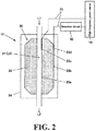
- FIG. 2 is a diagram showing a configuration of a sample oxidizing portion in the TOC meter of FIG. 1
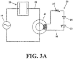
- FIG. 3A is a diagram showing wiring of a high-frequency power source UV lamp and a high-frequency power source UV lamp monitor included in the sample oxidizing portion.
- TC total carbon
- IC inorganic carbon
- the TOC meter 10 is provided with a flow path L to which a sample solution is supplied from a sample introduction port 11 for on-line measurement, a sample oxidizing portion 12 provided in the middle of the flow path L, a conductivity cell 13 for detecting the concentration of carbon dioxide by a conductivity sensor, and a liquid feed pump 14, such as, e.g., a tube pump, for feeding a sample solution and passing it through the flow path L.
- a sample solution is supplied from a sample introduction port 11 for on-line measurement
- a sample oxidizing portion 12 provided in the middle of the flow path L
- a conductivity cell 13 for detecting the concentration of carbon dioxide by a conductivity sensor
- a liquid feed pump 14 such as, e.g., a tube pump
- a flow path extending from the sample introduction port 11 to the sample oxidizing portion 12 is defined as a flow path L1
- a flow path in the sample oxidizing portion 12 is a flow path L2
- a flow path extending from the sample oxidizing portion 12 to the conductivity cell 13 is defined as a flow path L3
- a flow path in the the conductivity cell 13 is defined as a flow path L4.
- the sample oxidizing portion 12 has a built-in excimer UV lamp (high-frequency power source UV lamp) 20 connected to a high-frequency power source 19.
- the excimer UV lamp 20 has a double tube structure, and the inner tube 21 thereof is served as a part of a flow path L (i.e., a flow path L2) for oxidizing a sample solution and delivering it to the conductivity cell 13.
- a rare gas e.g., xenon
- Electrodes 22c and 22d are provided on the inner wall 22a and the outer wall 22b of the outer tube 22, respectively, and the electrodes 22c and 22d are connected to a high-frequency power source 19 of 10kHz to 1,000 kHz via a feeder 23.
- a feeder 23 For example, it is configured such that when a high-frequency power of 100 kHz is applied from the high-frequency power source 19, ultraviolet rays generated by dielectric barrier discharge are irradiated toward the inner tube 21.
- the excimer UV lamp 20 is accommodated in a hermetically sealed container 24 so that ultraviolet rays and air containing harmful ozone do not leak from the inside of the hermetically sealed container 24 to the outside.
- a detection circuit 30 for performing lighting confirmation is attached to a portion located outside the hermetically sealed container 24 in the feeder 23 connecting the high-frequency power source 19 and the excimer UV lamp 20.
- the detection circuit 30 is composed of a core member (toroidal core or ferrite core) 31 made of a magnetically permeable material and attached to the outer periphery of the feeder 23 in a ring shape, an induction circuit 32 wound around the core member 31 in a coil shape to extract a high-frequency induction current, and an LED (detection element) 33 connected to the induction circuit 32.
- the induction circuit 32 is also provided with a rectifying diode 34 and a protective resistor 35 for rectification and protection of the LED 33.
- the liquid feed pump 14 is stopped and the excimer UV lamp 20 is turned on. In this state, ultraviolet irradiation is performed for about one minute. As a result, the total carbon (TC) of the sample solution staying in the inner tube 21 (flow path L2) of the sample oxidizing portion 12 is oxidized to be converted into carbon dioxide.
- the sample solution (unoxidized sample solution) in the flow path L3 between the sample oxidizing portion 12 and the conductivity cell 13 flows for a while in the conductivity cell 13, and then the sample solution oxidized in the sample oxidizing portion 12 (flow path L2) reaches the conductivity cell 13.
- the amount of carbon dioxide at this time is detected as the total carbon (TC).
- the time from the completion time T1 of passing the unoxidized sample solution in the flow path L3 to the completion time T2 of passing the sample solution oxidized in the flow path L2 in the conductivity cell is substantially determined by the relationship between the volumes of the flow paths L2 and L3. Therefore, the amount of carbon dioxide is continuously detected with the conductivity cell 13 until at least a period including before and after centering the period from the time T1 to the time T2 elapses, and the peak value of the detection signal of the conductivity cell 13 detected during that period is acquired as a signal of the total carbon (TC).
- the total organic carbon (TOC) concentration is calculated from the values of the inorganic carbon (IC) and the total carbon (TC) obtained immediately before based on the equation (1).
- the first measurement is completed.
- the sample solution When measuring the total carbon (TC) concentration, the sample solution is made to be retained in the inner tube 21 (flow path L2) of the sample oxidizing portion 12 and high-frequency power is supplied from the high-frequency power source 19 to excite the excimer UV lamp 20 to start discharge.
- the ultraviolet rays irradiated from the excimer UV lamp 20 an oxidation reaction occurs in the total carbon (TC) in the sample solution, and the total carbon (TC) is converted into carbon dioxide.
- the measurement of the total carbon (TC) concentration is performed without the oxidation reaction being performed, and an erroneous measurement result is shown, so that the user needs to confirm the lighting of the excimer UV lamp 20 using the detection circuit 30 before the measurement.
- high-frequency energy is supplied from the high-frequency power source 19 to the excimer UV lamp 20 via the feeder 23, so electromagnetic waves are generated around the feeder 23 by the high-frequency energy in the feeder 23.
- the generated electromagnetic waves are extracted as a high-frequency induction current by the core member 31 attached to the feeder 23 at a position outside the hermetically sealed container 24 and having high magnetic permeability and the induction circuit 32.
- the LED 33 emits light. Therefore, the lighting of the excimer UV lamp 20 can be confirmed by the lighting of the LED 33.
- the detection circuit 30 may be any other detection circuit as long as it is a circuit for extracting and detecting an induced current.
- An example is shown in FIG. 3B .
- the reference numeral "35” denotes a protective resistor
- the reference numeral “36” denotes a capacitor for AC passage
- the reference numeral "37” denotes a protective diode.
- the resistor element may be used as a detection element to detect a voltage signal.
- the detected voltage signal may be compared with a threshold voltage set in advance to judge whether or not lighting is on, and when it is equal to or larger than the threshold value, it is judged that lighting is on, and when it is less than the threshold value, it is judged that lighting is off, and the judgment results may be notified by a detection means, such as, e.g., a buzzer.
- the excimer UV lamp 20 used in the above embodiment since the sample solution passes through the inner tube 21 (flow path L2), it is enough that only the inner tube 21 is irradiated with ultraviolet rays. Therefore, by forming the outer peripheral surface of the outer tube 22 with a material which does not allow transmission of ultraviolet rays, or by adhering or covering the outer tube 22 with a material which does not allow transmission of ultraviolet rays, it is possible to safely use the outer tube 22 without using the hermetically sealed container 24 while eliminating the problems of external irradiation of ultraviolet rays or harmful ozone generation.
- the present invention can be used as a lamp monitor of a UV lamp used in a TOC meter.
Landscapes
- Chemical & Material Sciences (AREA)
- Life Sciences & Earth Sciences (AREA)
- Health & Medical Sciences (AREA)
- Physics & Mathematics (AREA)
- General Physics & Mathematics (AREA)
- Engineering & Computer Science (AREA)
- Pathology (AREA)
- Analytical Chemistry (AREA)
- Biochemistry (AREA)
- General Health & Medical Sciences (AREA)
- Immunology (AREA)
- Medicinal Chemistry (AREA)
- Food Science & Technology (AREA)
- Mechanical Engineering (AREA)
- Chemical Kinetics & Catalysis (AREA)
- Electrochemistry (AREA)
- Investigating Or Analyzing Non-Biological Materials By The Use Of Chemical Means (AREA)
- Physical Water Treatments (AREA)
- Investigating Or Analyzing Materials By The Use Of Electric Means (AREA)
Abstract
Description
- The present invention relates to a UV lamp monitor attached to a UV lamp (ultraviolet lamp) for monitoring the lighting state thereof and a total organic carbon meter (hereinafter referred to as "TOC meter") using the same, and more particularly, to a high-frequency power source UV lamp monitor attached to a high-frequency power source UV lamp for emitting ultraviolet rays using a high-frequency power source, such as, e.g., an excimer lamp, and a TOC meter using the same.
- When measuring an organic substance contained in sample water, such as, e.g., wastewater, a TOC meter is used to measure the amount of carbon contained in the organic substance. In the TOC meter using a wet oxidation method, a sample oxidizing portion for oxidizing and decomposing an organic substance by irradiating ultraviolet rays to the sample water to be analyzed is provided. In this oxidizing portion, a low-pressure mercury lamp, which is easily available, is used as a UV lamp for emitting ultraviolet rays having a wavelength shorter than 200 nm.
- In a TOC meter using a UV lamp, the total carbon (TC) amount is measured by the amount of carbon dioxide generated from the total carbon (TC) in the sample water by supplying power from a power source and turning on the UV lamp to cause an oxidation reaction in the sample water. At this time, in order to prevent the ultraviolet rays of the sample oxidizing portion from leaking to the outside for the reasons that it is dangerous if the ultraviolet rays are directly irradiated to eyes and it is necessary to prevent generation of harmful ozone due to irradiation of ultraviolet rays to oxygen in the air, or the like, for example, the sample oxidizing portion is configured by a housing having a hermetically sealed structure and the UV lamp is built in the housing (see Patent Document 1).
- On the other hand, if the UV lamp is not turned on due to a failure or abnormality even though the power is in a turned-on state during the analysis and measurement, the oxidation reaction is not performed, so that an erroneous measurement result is shown. For this reason, it is necessary to confirm whether or not the UV lamp is turned on in the power-on state before starting the measurement.
- In the UV lamp built in the housing having the above-described hermetically sealed structure, however, it is impossible to confirm the lighting state. Therefore, it is disclosed that a lighting confirmation window made of a material that allows transmission of visible light and does not allow transmission of ultraviolet rays is provided in a housing and that a sealed portion (lead wire leading out portion) of a UV lamp tube body in which an ultraviolet radiation gas is sealed is formed of a resin having a property of allowing transmission of visible light while shielding ultraviolet rays and the sealed portion is configured to protrude from the housing so that visible light can be visually recognized from the sealed portion when the UV lamp is turned on (see Patent Document 2).
- In addition to the lighting confirmation method described in the above Patent Document, for example, a photosensor for measuring illuminance of a UV lamp is attached as a lamp monitor to confirm lighting in a housing of a sample oxidizing portion in which the UV lamp is built-in (see Patent Document 1).
-
- Patent Document 1: Japanese Unexamined Patent Application Publication No.
2007-040729 - Patent Document 2: Japanese Unexamined Patent Application Publication No.
2010-266222 - The method of forming a window in the housing itself in which a UV lamp is built-in or using a resin that allow transmission of visible light while shielding ultraviolet light in the sealed portion of the UV lamp tube is useful as a method of confirming lighting of a UV lamp. However, in the former method, it is necessary to hermetically seal the window to form a sealed structure, and in the latter case, a UV lamp with special specifications is necessary.
- Further, although a method of arranging a UV lamp and a photosensor for lighting confirmation in parallel in a housing having a hermetically sealed structure is also useful, it is necessary to separately provide wiring for a photosensor and a driving power source. Further, in the event of a failure of the photosensor, there is a fear that a signal indicating that the UV lamp is turned off is erroneously transmitted even though the UV lamp is in a normally turned-on state.
- On the other hand, in the UV lamp of the TOC meter, it is desirable to use a UV lamp not using mercury instead of a conventional low-pressure mercury lamp in consideration of the environmental aspect of demercuriation, apart from the above-mentioned structural problem. As a UV lamp that can obtain ultraviolet rays of 200 nm or less and does not use mercury, although it is conceivable to use a xenon arc lamp. However, even if demercuriation is achieved by a xenon arc lamp, the problem at the time of confirming the lighting of the UV lamp in the hermetically sealed housing cannot be solved.
- Therefore, the present invention aims to provide a high-frequency power source UV lamp monitor capable of easily confirming lighting of a high-frequency power source UV lamp built in a housing having a hermetically sealed structure. The present invention also aims to provide a TOC meter using a high-frequency power source UV lamp monitor capable of achieving demercuriation by a high-frequency power source UV lamp that does not use mercury and performing lighting confirmation by a simple method.
- A high-frequency power source UV lamp monitor according to the present invention, which has been made to solve the above-mentioned problems, is a high-frequency power source UV lamp monitor attached to a high-frequency power source UV lamp which emits ultraviolet light by supplying high-frequency energy from a high-frequency power source via a feeder. The high-frequency power source UV lamp monitor includes a detection circuit having a core member attached around the feeder in a ring shape and made of a magnetically permeable material, an induction circuit wound around the core member to extract a high-frequency induction current, and a detection element connected to the induction circuit.
- Here, the "high-frequency power source UV lamp" refers to a lamp in which discharge is performed by supplying high-frequency energy having a frequency of 10 kHz or more. More specifically, an excimer lamp, a xenon flash lamp, or the like, which emits ultraviolet light having a wavelength shorter than 200 nm by dielectric barrier discharge, corresponds to the lamp.
- The "detection element" may be any element capable of detecting as a signal that a high-frequency induced current has flowed through the induction circuit, and specifically, an LED capable of detecting as a light emission signal is desirable.
- Further, a total organic carbon meter according to the present invention, which has been made from another viewpoint, is a total organic carbon meter including a sample oxidizing portion for oxidizing carbon contained in a sample solution by irradiation with ultraviolet rays to convert the carbon into carbon dioxide, wherein the sample oxidizing portion uses a high-frequency power source UV lamp for emitting ultraviolet rays by supplying high-frequency energy from a high-frequency power source via a feeder, and is provided with a high-frequency power source UV lamp monitor for confirming lighting of the high-frequency power source UV lamp, and wherein the high-frequency power source UV lamp monitor is provided with a core member attached around the feeder in a ring shape and made of a magnetically permeable material, an induction circuit wound around the core member for extracting a high-frequency induction current, and a detecting element connected to the induction circuit.
- According to the present invention, the high-frequency power source UV lamp is turned on when high-frequency energy is supplied from the high-frequency power source. At this time, some deviation of the impedance matching occurs in the feeder connecting the high-frequency power source and the high-frequency power source UV lamp, so that the common mode current is induced by the influence of the deviation. Although impedance matching can theoretically be mitigated by incorporating a matching circuit, it is difficult to completely cancel out. Further, in the present invention, since it is only necessary to turn on the high-frequency power source UV lamp, it is unnecessary to provide a matching circuit if the impedance matching is not excessively deviated, and it is possible to obtain an induced current by supplying high-frequency energy without performing the matching adjustment.
- In this manner, electromagnetic waves are generated around the feeder by the high-frequency energy, and are extracted as a high-frequency induction current by the induction circuit wound around the core member around the feeder. At this time, if a high-frequency induction current is flowing, it can be detected by the detection element connected to the induction circuit, so that the lighting can be confirmed by this detection element.
- According to the high-frequency power source UV lamp monitor of the present invention, the lighting of the high-frequency power source UV lamp can be easily confirmed by detecting the high-frequency induction current generated around the feeder outside the container with the detection element in a state in which the high-frequency power source UV lamp is built in the hermetically sealed container. Therefore, it is possible to confirm the lighting of the lamp in the hermetically sealed container safely without risk of the ultraviolet rays entering eyes of the user and without leakage of harmful ozone.
- Further, according to the high-frequency power UV lamp monitor of the present invention, it is possible to confirm lighting without providing wiring for extracting a signal from the inside of the hermetically sealed container to the outside or a photosensor or the like which requires a drive power source separately.
- Further, by employing the TOC meter using the high-frequency power source UV lamp monitor of the present invention, the TOC meter can be applied to confirmation of lighting of the high-frequency power source UV lamp used in the sample oxidizing portion of the TOC meter, and moreover, the TOC meter can be provided without using a mercury lamp having a large environmental load.
-
-
FIG. 1 is a configuration diagram showing a TOC meter using a high-frequency power source UV lamp monitor according to the present invention. -
FIG. 2 is a diagram showing a configuration of a sample oxidizing portion ofFIG. 1 . -
FIG. 3A is a wiring diagram of a high-frequency power source UV lamp and a monitor in the sample oxidizing portion ofFIG. 1 . -
FIG. 3B is a wiring diagram showing a modified embodiment of the detector inFIG. 3A . - Hereinafter, an embodiment in which a high-frequency power source UV lamp monitor according to the present invention is applied to a TOC meter will be described with reference to the attached drawings.
FIG. 1 is a configuration diagram showing the TOC meter for on-line measurement using a high-frequency power source UV lamp monitor according to an embodiment of the present invention.FIG. 2 is a diagram showing a configuration of a sample oxidizing portion in the TOC meter ofFIG. 1 , andFIG. 3A is a diagram showing wiring of a high-frequency power source UV lamp and a high-frequency power source UV lamp monitor included in the sample oxidizing portion. - In the TOC meter in this embodiment, a total carbon (TC) and an inorganic carbon (IC) in a sample solution are measured, and the difference is calculated. That is, the total organic carbon (TOC) concentration can be obtained by the following equation (1).
TOC = TC-IC - - - (1)
- As shown in
FIG. 1 , theTOC meter 10 is provided with a flow path L to which a sample solution is supplied from asample introduction port 11 for on-line measurement, asample oxidizing portion 12 provided in the middle of the flow path L, aconductivity cell 13 for detecting the concentration of carbon dioxide by a conductivity sensor, and aliquid feed pump 14, such as, e.g., a tube pump, for feeding a sample solution and passing it through the flow path L. - Hereinafter, for convenience of description, a flow path extending from the
sample introduction port 11 to thesample oxidizing portion 12 is defined as a flow path L1, a flow path in thesample oxidizing portion 12 is a flow path L2, a flow path extending from thesample oxidizing portion 12 to theconductivity cell 13 is defined as a flow path L3, and a flow path in the theconductivity cell 13 is defined as a flow path L4. - The
sample oxidizing portion 12 has a built-in excimer UV lamp (high-frequency power source UV lamp) 20 connected to a high-frequency power source 19. - As shown in
FIG. 2 , theexcimer UV lamp 20 has a double tube structure, and theinner tube 21 thereof is served as a part of a flow path L (i.e., a flow path L2) for oxidizing a sample solution and delivering it to theconductivity cell 13. A rare gas (e.g., xenon) is sealed in theouter tube 22.Electrodes inner wall 22a and theouter wall 22b of theouter tube 22, respectively, and theelectrodes frequency power source 19 of 10kHz to 1,000 kHz via afeeder 23. For example, it is configured such that when a high-frequency power of 100 kHz is applied from the high-frequency power source 19, ultraviolet rays generated by dielectric barrier discharge are irradiated toward theinner tube 21. - The
excimer UV lamp 20 is accommodated in a hermetically sealedcontainer 24 so that ultraviolet rays and air containing harmful ozone do not leak from the inside of the hermetically sealedcontainer 24 to the outside. - Further, a
detection circuit 30 for performing lighting confirmation is attached to a portion located outside the hermetically sealedcontainer 24 in thefeeder 23 connecting the high-frequency power source 19 and theexcimer UV lamp 20. Thedetection circuit 30 is composed of a core member (toroidal core or ferrite core) 31 made of a magnetically permeable material and attached to the outer periphery of thefeeder 23 in a ring shape, aninduction circuit 32 wound around thecore member 31 in a coil shape to extract a high-frequency induction current, and an LED (detection element) 33 connected to theinduction circuit 32. Theinduction circuit 32 is also provided with a rectifyingdiode 34 and aprotective resistor 35 for rectification and protection of theLED 33. - When the measurement is performed using such a
TOC meter 10, first, in a state in which theexcimer UV lamp 20 is turned off, the sample solution is continuously sucked into the flow path L by theliquid feed pump 14 at a constant flow rate, and the entire flow path L (flow paths L1 to L4) is filled with the sample solution. At this time, since a sample solution not irradiated with ultraviolet rays, that is, a unoxidized sample solution, is flowing through the conductivity cell 13 (flow path L4), the amount of carbon dioxide in the sample solution at this time is detected by theconductivity cell 13 as a signal of inorganic carbon (IC). - Subsequently, the
liquid feed pump 14 is stopped and theexcimer UV lamp 20 is turned on. In this state, ultraviolet irradiation is performed for about one minute. As a result, the total carbon (TC) of the sample solution staying in the inner tube 21 (flow path L2) of thesample oxidizing portion 12 is oxidized to be converted into carbon dioxide. - Thereafter, when the
excimer UV lamp 20 is turned off and suction of the sample solution is resumed at a constant flow rate by theliquid feed pump 14, the sample solution (unoxidized sample solution) in the flow path L3 between thesample oxidizing portion 12 and theconductivity cell 13 flows for a while in theconductivity cell 13, and then the sample solution oxidized in the sample oxidizing portion 12 (flow path L2) reaches theconductivity cell 13. The amount of carbon dioxide at this time is detected as the total carbon (TC). - More specifically, when the sample solution is sucked at a constant flow rate, the time from the completion time T1 of passing the unoxidized sample solution in the flow path L3 to the completion time T2 of passing the sample solution oxidized in the flow path L2 in the conductivity cell is substantially determined by the relationship between the volumes of the flow paths L2 and L3. Therefore, the amount of carbon dioxide is continuously detected with the
conductivity cell 13 until at least a period including before and after centering the period from the time T1 to the time T2 elapses, and the peak value of the detection signal of theconductivity cell 13 detected during that period is acquired as a signal of the total carbon (TC). - Then, the total organic carbon (TOC) concentration is calculated from the values of the inorganic carbon (IC) and the total carbon (TC) obtained immediately before based on the equation (1). Thus, the first measurement is completed.
- Subsequently, when the sample solution is continuously sucked by the
liquid feed pump 14 even after completion of the first measurement, all the flow paths L (L1 to L4) including theconductivity cell 13 are filled with the replaced unoxidized sample solution. - Therefore, by repeating the above measurement flow, it is possible to continuously perform the second and subsequent measurement of the total organic carbon (TOC) concentration.
- Next, the lighting confirmation flow of the
excimer UV lamp 20, which is a feature of the present invention, will be described. - When measuring the total carbon (TC) concentration, the sample solution is made to be retained in the inner tube 21 (flow path L2) of the
sample oxidizing portion 12 and high-frequency power is supplied from the high-frequency power source 19 to excite theexcimer UV lamp 20 to start discharge. Thus, by the action of the ultraviolet rays irradiated from theexcimer UV lamp 20, an oxidation reaction occurs in the total carbon (TC) in the sample solution, and the total carbon (TC) is converted into carbon dioxide. - However, in cases where ultraviolet rays are not irradiated due to a failure or malfunction of the
excimer UV lamp 20, the measurement of the total carbon (TC) concentration is performed without the oxidation reaction being performed, and an erroneous measurement result is shown, so that the user needs to confirm the lighting of theexcimer UV lamp 20 using thedetection circuit 30 before the measurement. - That is, in the ultraviolet irradiation in the
sample oxidizing portion 12, high-frequency energy is supplied from the high-frequency power source 19 to theexcimer UV lamp 20 via thefeeder 23, so electromagnetic waves are generated around thefeeder 23 by the high-frequency energy in thefeeder 23. The generated electromagnetic waves are extracted as a high-frequency induction current by thecore member 31 attached to thefeeder 23 at a position outside the hermetically sealedcontainer 24 and having high magnetic permeability and theinduction circuit 32. When the high-frequency induction current flows to theLED 33 via the rectifyingdiode 34 connected to theinduction circuit 32, theLED 33 emits light. Therefore, the lighting of theexcimer UV lamp 20 can be confirmed by the lighting of theLED 33. - Although an embodiment of the present invention has been specifically described above, the present invention is not necessarily limited to the above-described embodiment, and it is needless to say that the present invention can be appropriately modified and changed within the scope not departing from the spirit of the present invention. Hereinafter, a modified embodiment thereof will be described.
- The
detection circuit 30 may be any other detection circuit as long as it is a circuit for extracting and detecting an induced current. An example is shown inFIG. 3B . In the detector 30' ofFIG. 3B , the reference numeral "35" denotes a protective resistor, the reference numeral "36" denotes a capacitor for AC passage, and the reference numeral "37" denotes a protective diode. - In the embodiment described above, the resistor element may be used as a detection element to detect a voltage signal. In this case, the detected voltage signal may be compared with a threshold voltage set in advance to judge whether or not lighting is on, and when it is equal to or larger than the threshold value, it is judged that lighting is on, and when it is less than the threshold value, it is judged that lighting is off, and the judgment results may be notified by a detection means, such as, e.g., a buzzer.
- Further, in the
excimer UV lamp 20 used in the above embodiment, since the sample solution passes through the inner tube 21 (flow path L2), it is enough that only theinner tube 21 is irradiated with ultraviolet rays. Therefore, by forming the outer peripheral surface of theouter tube 22 with a material which does not allow transmission of ultraviolet rays, or by adhering or covering theouter tube 22 with a material which does not allow transmission of ultraviolet rays, it is possible to safely use theouter tube 22 without using the hermetically sealedcontainer 24 while eliminating the problems of external irradiation of ultraviolet rays or harmful ozone generation. - The present invention can be used as a lamp monitor of a UV lamp used in a TOC meter.
-
- 10:
- TOC meter (total organic carbon meter)
- 11:
- sample introduction port
- 12:
- sample oxidizing portion
- 13:
- conductivity cell
- 19:
- high-frequency power source
- 20:
- excimer UV lamp (high-frequency power source UV lamp)
- 21:
- inner tube
- 22:
- outer tube
- 22c, 22d:
- electrode
- 23:
- feeder
- 24:
- hermetically sealed housing
- 30:
- detection circuit
- 31:
- core member
- 32:
- induction circuit
- 33:
- LED (detection element)
- 34:
- rectifying diode
- 35:
- protective resistance
- 36:
- capacitor
- 37:
- protective diode
Claims (3)
- A high-frequency power source UV lamp monitor to be attached to a high-frequency power source UV lamp which emits ultraviolet light by supplying high-frequency energy from a high-frequency power source via a feeder, the high-frequency power source UV lamp monitor comprising:
a detection circuit including a core member attached around the feeder in a ring shape and made of a magnetically permeable material, an induction circuit wound around the core member to extract a high-frequency induction current, and a detection element connected to the induction circuit. - The high-frequency power source UV lamp monitor as cited in claim 1,
wherein the detection element is an LED. - A total organic carbon meter provided with a sample oxidizing portion for oxidizing carbon contained in a sample solution by irradiation with ultraviolet rays to convert the carbon into carbon dioxide,
wherein the sample oxidizing portion uses a high-frequency power source UV lamp for emitting ultraviolet rays by supplying high-frequency energy from a high-frequency power source via a feeder, and is provided with a high-frequency power source UV lamp monitor for confirming lighting of the high-frequency power source UV lamp, and
wherein the high-frequency power source UV lamp monitor comprises a detection circuit including a core member attached around the feeder in a ring shape and made of a magnetically permeable material, an induction circuit wound around the core member to extract a high-frequency induction current, and a detection element connected to the induction circuit.
Applications Claiming Priority (2)
| Application Number | Priority Date | Filing Date | Title |
|---|---|---|---|
| JP2017169420 | 2017-09-04 | ||
| PCT/JP2018/031895 WO2019044881A1 (en) | 2017-09-04 | 2018-08-29 | High-frequency-power-source uv lamp monitor, and total organic carbon meter in which same is used |
Publications (2)
| Publication Number | Publication Date |
|---|---|
| EP3680655A1 true EP3680655A1 (en) | 2020-07-15 |
| EP3680655A4 EP3680655A4 (en) | 2021-06-09 |
Family
ID=65525740
Family Applications (1)
| Application Number | Title | Priority Date | Filing Date |
|---|---|---|---|
| EP18850855.0A Withdrawn EP3680655A4 (en) | 2017-09-04 | 2018-08-29 | High-frequency-power-source uv lamp monitor, and total organic carbon meter in which same is used |
Country Status (5)
| Country | Link |
|---|---|
| US (1) | US20200225293A1 (en) |
| EP (1) | EP3680655A4 (en) |
| JP (1) | JP6828822B2 (en) |
| CN (1) | CN111033250A (en) |
| WO (1) | WO2019044881A1 (en) |
Family Cites Families (11)
| Publication number | Priority date | Publication date | Assignee | Title |
|---|---|---|---|---|
| US5750073A (en) * | 1990-03-02 | 1998-05-12 | Sievers Instruments, Inc. | Reagentless oxidation reactor in a carbon measuring system |
| JP2854797B2 (en) * | 1994-02-22 | 1999-02-03 | 中国電力株式会社 | Electric wire sign light |
| US6444474B1 (en) * | 1998-04-22 | 2002-09-03 | Eltron Research, Inc. | Microfluidic system for measurement of total organic carbon |
| JP3268447B2 (en) * | 1999-06-02 | 2002-03-25 | 独立行政法人産業技術総合研究所 | Photoreaction device with built-in photoreaction tube |
| JP2004158373A (en) * | 2002-11-08 | 2004-06-03 | Orc Mfg Co Ltd | Excimer lamp |
| CN1275277C (en) * | 2002-12-06 | 2006-09-13 | 株式会社Orc制作所 | excimer lamp |
| JP2007040729A (en) | 2005-08-01 | 2007-02-15 | Shimadzu Corp | Total organic carbon meter |
| JP2008008848A (en) * | 2006-06-30 | 2008-01-17 | Kobe Steel Ltd | UV monitoring system and UV irradiation device |
| CA2675869A1 (en) * | 2008-08-18 | 2010-02-18 | Sanuvox Technologies Inc. | Controller for uv light purification system |
| WO2010122655A1 (en) * | 2009-04-24 | 2010-10-28 | 株式会社島津製作所 | Total organic carbon meter provided with system blank function |
| JP5104813B2 (en) | 2009-05-12 | 2012-12-19 | 株式会社島津製作所 | Ultraviolet irradiation device and total organic carbon measuring device using the same |
-
2018
- 2018-08-29 EP EP18850855.0A patent/EP3680655A4/en not_active Withdrawn
- 2018-08-29 US US16/641,589 patent/US20200225293A1/en not_active Abandoned
- 2018-08-29 JP JP2019539565A patent/JP6828822B2/en active Active
- 2018-08-29 CN CN201880054688.8A patent/CN111033250A/en not_active Withdrawn
- 2018-08-29 WO PCT/JP2018/031895 patent/WO2019044881A1/en not_active Ceased
Also Published As
| Publication number | Publication date |
|---|---|
| JP6828822B2 (en) | 2021-02-10 |
| US20200225293A1 (en) | 2020-07-16 |
| CN111033250A (en) | 2020-04-17 |
| JPWO2019044881A1 (en) | 2020-03-26 |
| EP3680655A4 (en) | 2021-06-09 |
| WO2019044881A1 (en) | 2019-03-07 |
Similar Documents
| Publication | Publication Date | Title |
|---|---|---|
| KR101795827B1 (en) | Wirelessly powered dielectric barrier discharge lamp, and base station for a wirelessly powered fluid treatment system | |
| CA2160407A1 (en) | Stent which can be implanted into a body vessel | |
| US20020079902A1 (en) | Sensor for measuring the electrical conductivity of a fluid medium | |
| BR112019002736B1 (en) | SYSTEM, USE OF THE SYSTEM, METHOD FOR PERFORMING A CONDUCTIVITY MEASUREMENT OF A FLUID, SENSOR FOR DETERMINING THE CONDUCTIVITY OF A FLUID, AND, USE OF THE SENSOR | |
| CN104730267B (en) | TOC, TN, TP concentration and total amount continuous synchronous online monitoring method and instrument | |
| EP3680655A1 (en) | High-frequency-power-source uv lamp monitor, and total organic carbon meter in which same is used | |
| US9194685B2 (en) | Retractable assembly | |
| ES2364441T3 (en) | CONSUMER METER WITH MAGNETIC FIELD DETECTOR. | |
| EP2869043B1 (en) | Hybrid connection device | |
| CN104115009A (en) | Total nitrogen measurement apparatus | |
| EP2327357A1 (en) | Detection of water in electrical devices | |
| US6781389B1 (en) | Conductivity sensor for detecting conductivity of a fluid | |
| CN104792704B (en) | Tri- index continuous synchronization real-time online determining instrument of TOC, TN, TP | |
| IT201800002751A1 (en) | DETECTION AND / OR CONTROL DEVICE FOR LIQUID-CONDUCTED EQUIPMENT OR SYSTEMS | |
| JP2007237179A (en) | Ultraviolet device for sterilizing water in 24-hour bathing water purifying and circulating apparatus | |
| EP4215910B1 (en) | System for limiting water within a photoionization detector | |
| US20150362545A1 (en) | Fluorescent lamp testing device | |
| JP5104813B2 (en) | Ultraviolet irradiation device and total organic carbon measuring device using the same | |
| US12216083B2 (en) | Method for detecting presence/absence of liquid suctioned by syringe pump, and device with syringe pump | |
| CN102625949A (en) | Method and system for monitoring performance of a discharge lamp and corresponding lamp | |
| JP2009204431A (en) | Measuring method of chemical oxygen demand | |
| KR102685747B1 (en) | Thermometer | |
| TWI509226B (en) | Electromagnetic Flowmeter with Frequency Conductivity-Sensing Function | |
| CN105784042A (en) | Non-contact-type water quality detection water meter | |
| CN101324464A (en) | Underwater C waveband ultraviolet ray strength detector |
Legal Events
| Date | Code | Title | Description |
|---|---|---|---|
| STAA | Information on the status of an ep patent application or granted ep patent |
Free format text: STATUS: THE INTERNATIONAL PUBLICATION HAS BEEN MADE |
|
| PUAI | Public reference made under article 153(3) epc to a published international application that has entered the european phase |
Free format text: ORIGINAL CODE: 0009012 |
|
| STAA | Information on the status of an ep patent application or granted ep patent |
Free format text: STATUS: REQUEST FOR EXAMINATION WAS MADE |
|
| 17P | Request for examination filed |
Effective date: 20200319 |
|
| AK | Designated contracting states |
Kind code of ref document: A1 Designated state(s): AL AT BE BG CH CY CZ DE DK EE ES FI FR GB GR HR HU IE IS IT LI LT LU LV MC MK MT NL NO PL PT RO RS SE SI SK SM TR |
|
| AX | Request for extension of the european patent |
Extension state: BA ME |
|
| DAV | Request for validation of the european patent (deleted) | ||
| DAX | Request for extension of the european patent (deleted) | ||
| A4 | Supplementary search report drawn up and despatched |
Effective date: 20210510 |
|
| RIC1 | Information provided on ipc code assigned before grant |
Ipc: G01N 33/18 20060101AFI20210503BHEP Ipc: G01N 31/00 20060101ALI20210503BHEP Ipc: G01N 27/06 20060101ALI20210503BHEP |
|
| STAA | Information on the status of an ep patent application or granted ep patent |
Free format text: STATUS: THE APPLICATION HAS BEEN WITHDRAWN |
|
| 18W | Application withdrawn |
Effective date: 20211008 |