EP3680624B1 - Sensor assembly - Google Patents
Sensor assembly Download PDFInfo
- Publication number
- EP3680624B1 EP3680624B1 EP19151358.9A EP19151358A EP3680624B1 EP 3680624 B1 EP3680624 B1 EP 3680624B1 EP 19151358 A EP19151358 A EP 19151358A EP 3680624 B1 EP3680624 B1 EP 3680624B1
- Authority
- EP
- European Patent Office
- Prior art keywords
- optical
- sensor
- track
- vehicle
- optical sensor
- Prior art date
- Legal status (The legal status is an assumption and is not a legal conclusion. Google has not performed a legal analysis and makes no representation as to the accuracy of the status listed.)
- Active
Links
- 230000003287 optical effect Effects 0.000 claims description 158
- 238000001514 detection method Methods 0.000 claims description 11
- 239000000758 substrate Substances 0.000 claims description 6
- 238000002310 reflectometry Methods 0.000 claims 1
- 238000011156 evaluation Methods 0.000 description 10
- 238000012360 testing method Methods 0.000 description 5
- 238000005259 measurement Methods 0.000 description 4
- 230000005693 optoelectronics Effects 0.000 description 4
- 239000003086 colorant Substances 0.000 description 3
- 230000007704 transition Effects 0.000 description 3
- 230000001419 dependent effect Effects 0.000 description 2
- 238000013461 design Methods 0.000 description 2
- 230000033001 locomotion Effects 0.000 description 2
- 238000000034 method Methods 0.000 description 2
- 239000000853 adhesive Substances 0.000 description 1
- 238000004026 adhesive bonding Methods 0.000 description 1
- 230000001070 adhesive effect Effects 0.000 description 1
- 230000005540 biological transmission Effects 0.000 description 1
- 230000000295 complement effect Effects 0.000 description 1
- 238000011161 development Methods 0.000 description 1
- 230000018109 developmental process Effects 0.000 description 1
- 230000000694 effects Effects 0.000 description 1
- 238000005286 illumination Methods 0.000 description 1
- 238000009434 installation Methods 0.000 description 1
- 239000003973 paint Substances 0.000 description 1
- 238000005507 spraying Methods 0.000 description 1
Images


Classifications
-
- G—PHYSICS
- G01—MEASURING; TESTING
- G01D—MEASURING NOT SPECIALLY ADAPTED FOR A SPECIFIC VARIABLE; ARRANGEMENTS FOR MEASURING TWO OR MORE VARIABLES NOT COVERED IN A SINGLE OTHER SUBCLASS; TARIFF METERING APPARATUS; MEASURING OR TESTING NOT OTHERWISE PROVIDED FOR
- G01D5/00—Mechanical means for transferring the output of a sensing member; Means for converting the output of a sensing member to another variable where the form or nature of the sensing member does not constrain the means for converting; Transducers not specially adapted for a specific variable
- G01D5/12—Mechanical means for transferring the output of a sensing member; Means for converting the output of a sensing member to another variable where the form or nature of the sensing member does not constrain the means for converting; Transducers not specially adapted for a specific variable using electric or magnetic means
- G01D5/244—Mechanical means for transferring the output of a sensing member; Means for converting the output of a sensing member to another variable where the form or nature of the sensing member does not constrain the means for converting; Transducers not specially adapted for a specific variable using electric or magnetic means influencing characteristics of pulses or pulse trains; generating pulses or pulse trains
- G01D5/245—Mechanical means for transferring the output of a sensing member; Means for converting the output of a sensing member to another variable where the form or nature of the sensing member does not constrain the means for converting; Transducers not specially adapted for a specific variable using electric or magnetic means influencing characteristics of pulses or pulse trains; generating pulses or pulse trains using a variable number of pulses in a train
- G01D5/2451—Incremental encoders
-
- B—PERFORMING OPERATIONS; TRANSPORTING
- B61—RAILWAYS
- B61L—GUIDING RAILWAY TRAFFIC; ENSURING THE SAFETY OF RAILWAY TRAFFIC
- B61L23/00—Control, warning, or like safety means along the route or between vehicles or vehicle trains
- B61L23/04—Control, warning, or like safety means along the route or between vehicles or vehicle trains for monitoring the mechanical state of the route
-
- B—PERFORMING OPERATIONS; TRANSPORTING
- B61—RAILWAYS
- B61L—GUIDING RAILWAY TRAFFIC; ENSURING THE SAFETY OF RAILWAY TRAFFIC
- B61L25/00—Recording or indicating positions or identities of vehicles or vehicle trains or setting of track apparatus
- B61L25/02—Indicating or recording positions or identities of vehicles or vehicle trains
- B61L25/025—Absolute localisation, e.g. providing geodetic coordinates
-
- G—PHYSICS
- G01—MEASURING; TESTING
- G01D—MEASURING NOT SPECIALLY ADAPTED FOR A SPECIFIC VARIABLE; ARRANGEMENTS FOR MEASURING TWO OR MORE VARIABLES NOT COVERED IN A SINGLE OTHER SUBCLASS; TARIFF METERING APPARATUS; MEASURING OR TESTING NOT OTHERWISE PROVIDED FOR
- G01D5/00—Mechanical means for transferring the output of a sensing member; Means for converting the output of a sensing member to another variable where the form or nature of the sensing member does not constrain the means for converting; Transducers not specially adapted for a specific variable
- G01D5/12—Mechanical means for transferring the output of a sensing member; Means for converting the output of a sensing member to another variable where the form or nature of the sensing member does not constrain the means for converting; Transducers not specially adapted for a specific variable using electric or magnetic means
- G01D5/244—Mechanical means for transferring the output of a sensing member; Means for converting the output of a sensing member to another variable where the form or nature of the sensing member does not constrain the means for converting; Transducers not specially adapted for a specific variable using electric or magnetic means influencing characteristics of pulses or pulse trains; generating pulses or pulse trains
- G01D5/245—Mechanical means for transferring the output of a sensing member; Means for converting the output of a sensing member to another variable where the form or nature of the sensing member does not constrain the means for converting; Transducers not specially adapted for a specific variable using electric or magnetic means influencing characteristics of pulses or pulse trains; generating pulses or pulse trains using a variable number of pulses in a train
- G01D5/2454—Encoders incorporating incremental and absolute signals
-
- G—PHYSICS
- G01—MEASURING; TESTING
- G01D—MEASURING NOT SPECIALLY ADAPTED FOR A SPECIFIC VARIABLE; ARRANGEMENTS FOR MEASURING TWO OR MORE VARIABLES NOT COVERED IN A SINGLE OTHER SUBCLASS; TARIFF METERING APPARATUS; MEASURING OR TESTING NOT OTHERWISE PROVIDED FOR
- G01D5/00—Mechanical means for transferring the output of a sensing member; Means for converting the output of a sensing member to another variable where the form or nature of the sensing member does not constrain the means for converting; Transducers not specially adapted for a specific variable
- G01D5/12—Mechanical means for transferring the output of a sensing member; Means for converting the output of a sensing member to another variable where the form or nature of the sensing member does not constrain the means for converting; Transducers not specially adapted for a specific variable using electric or magnetic means
- G01D5/244—Mechanical means for transferring the output of a sensing member; Means for converting the output of a sensing member to another variable where the form or nature of the sensing member does not constrain the means for converting; Transducers not specially adapted for a specific variable using electric or magnetic means influencing characteristics of pulses or pulse trains; generating pulses or pulse trains
- G01D5/249—Mechanical means for transferring the output of a sensing member; Means for converting the output of a sensing member to another variable where the form or nature of the sensing member does not constrain the means for converting; Transducers not specially adapted for a specific variable using electric or magnetic means influencing characteristics of pulses or pulse trains; generating pulses or pulse trains using pulse code
- G01D5/2492—Pulse stream
Definitions
- the invention relates to a sensor arrangement.
- Such sensor arrangements generally form optical tracking systems, by means of which a controlled movement of a vehicle along a defined path can be accomplished.
- the optical sensor is mounted on the vehicle. With the optical sensor, a track extending along the path of the vehicle is detected, which is in particular in the form of a strip having a specific color that is applied to a substrate, in particular the roadway on which the vehicle is driving.
- a track extending along the path of the vehicle is detected, which is in particular in the form of a strip having a specific color that is applied to a substrate, in particular the roadway on which the vehicle is driving.
- the strip that forms the track is applied to the floor of a factory building or even to the outside area of an industrial plant, for example by gluing the strip on or by spraying on an appropriate paint.
- the substrate can vary in terms of texture and color. This can mean that in some areas the background differs only slightly from the stripe forming the track in terms of color or contrast. This can mean that the lane can no longer be reliably detected by the optical sensor, which means that the vehicle can no longer be safely guided in the lane.
- the DE 10 2005 047 658 A1 relates to a device with a position measuring system formed by an arrangement of marks and with an optical sensor for detecting the marks of the position measuring system.
- the optical sensor and the position measuring system are arranged to be movable relative to one another.
- a sensor element is permanently assigned to the optical sensor, by means of which the marks of the position measuring system or markings of a measuring system permanently assigned to the position measuring system can be detected.
- the signals generated by the optical sensor and the sensor element are evaluated in an evaluation system.
- the EP 3 282 286 A1 relates to an optical sensor for detecting objects in a detection area and includes a light source emitting light beams, a receiver in the form of an image sensor having an array of receiving elements, an evaluation unit for evaluating received images of the image sensor.
- the optical sensor has a test light source emitting test light beams, the test light beams being guided onto the image sensor, as a result of which a variation of the receiver images is obtained.
- the evaluation unit is designed to separate and separately evaluate useful information of the received images from test information, which is formed by the variations in the received images caused by the test light beams.
- the EP 1 621 504 A1 relates to an elongate signal strip which has signal sections along its length, each containing at least two different pieces of information, each based on an optical property, a magnetic property or a property relating to a reflection of electromagnetic waves of the signal section and through at least one sensor device can be determined, information based on the same property being different from one another in alternating signal sections.
- the signal strip is used in a system for determining a state of motion of a moving body, in particular a car of an elevator installation.
- the EP 3 270 114 A1 relates to a sensor arrangement with a first position sensor and a first cooperative target assigned thereto, which delimit a detection area.
- First position measurement values are obtained by position measurements with the first position sensor against the first cooperative target.
- a second position sensor and a second cooperative target assigned to it are provided, which delimit the detection area.
- Second position readings are obtained by position measurements with the second position sensor against the second cooperative target.
- the function of the position sensors is checked with a control unit, in which the first and second measured position values of the two position sensors are offset to form a calculation variable.
- the EP 1 345 031 A2 relates to an optoelectronic device for detecting marks and has a transmitter emitting transmitted light beams, a receiver receiving received light beams, means for guiding the transmitted light beams within a scanning area and an evaluation unit for evaluating the received signals present at the output of the receiver.
- the marks to be recorded form a position measurement system.
- the US 2014/0368837 A1 relates to a detection system for determining the absolute value of a rail vehicle. Patterns are arranged at predetermined intervals along the rails on which the rail vehicle runs. These patterns are detected with a sensor emitting laser beams, with the light reflected by the patterns being evaluated. These measured values are compared with target values.
- JP HO480409 A relates to a vehicle-mounted barcode reader that reads barcodes arranged on a roadway. Information about the condition of the roadway is encoded in the barcodes.
- the US 2,996,137A relates to a radar system mounted on a vehicle.
- the radar system detects markings on a roadway by generating echo signals generated by the markings.
- the DE 20 2014 100 689 U1 relates to an optoelectronic device for position determination based on a position scale extending in a longitudinal direction with position marks, which has a light receiver for detecting image data of a position mark via a reading line and an evaluation unit for reading out position information encoded in the position mark from the image data.
- the reading line is tilted in relation to the longitudinal direction.
- the position scale has additional information associated with the position mark, which is arranged partially overlapping with the position mark, in such a way that the reading line only detects the additional information if the reading line does not completely sweep over the position mark anyway due to its tilting relative to the longitudinal direction.
- the invention is based on the object of providing a sensor arrangement of the type mentioned at the outset, which has a high level of functionality with little structural effort.
- the invention relates to a sensor arrangement with an optical sensor which is arranged on a vehicle.
- the vehicle is moved along a predetermined path.
- the sensor arrangement has an optical track which characterizes a trajectory and is applied to a stationary surface which forms a roadway on which the vehicle travels, the optical track having a contrasting pattern extending along its length.
- the optical sensor captures the contrast pattern of the optical lane while the vehicle is moving.
- the optical sensor works according to the light scanner principle. Tracking of the vehicle can be carried out as a function of output signals generated by the optical sensor.
- the contrast pattern is translation-invariant in the longitudinal direction of the optical track.
- the angular position of the optical sensor relative to the optical track is determined by detecting the contrast pattern.
- a major advantage of the invention is that the optical track has an intrinsic contrast pattern, i.e. a contrast pattern that forms contrast differences within the track, which can thus be reliably detected by the optical sensor, regardless of the nature of the substrate on which the optical track is applied.
- the contrast pattern of the optical track can thus be reliably detected by the optical sensor independently of the optical properties of the substrate, in particular independently of its reflectance.
- the optical sensor Depending on the detection of the optical track, the optical sensor then generates output signals that can be used to control the vehicle.
- Lane guidance of the vehicle can be carried out particularly advantageously as a function of output signals generated by the optical sensor.
- the ground on which the optical track is mounted is formed by the roadway on which the vehicle is driving.
- the optical sensor is then mounted in the area of the underside of the vehicle in such a way that it is arranged at a distance above the ground, so that this optical sensor can detect the optical track on the ground.
- the subsoil can also be formed by a hall ceiling or the like. Then the optical sensor can be arranged at the top of the vehicle to detect the optical lane.
- the contrast pattern is translation-invariant in the longitudinal direction of the optical track.
- the contrast pattern is thus formed in a translation-invariant manner in the longitudinal direction of the optical track.
- Such an optical track has an extremely simple structure and can accordingly be easily manufactured.
- an example of such an optical track is that the contrast pattern is formed by two strips with different remissions lying next to one another and extending in the longitudinal direction of the optical track.
- This contrast pattern has a particularly simple structure. Due to the two strips running in the longitudinal direction of the optical track with different remissions, a Contrast difference obtained, which can be easily and reliably detected with the optical sensor. It is essential that this difference in contrast is not on one of the longitudinal edges of the optical track, but in its central area. This means that influences from the remission of the background, regardless of whether it is strongly or weakly reflective, do not have a disruptive effect on the detection of the transition between the two strips, so that the contrast pattern can be reliably detected regardless of the nature of the background.
- the contrast pattern of the optical track has a contrast pattern that forms contrast differences in the inner area of the optical track, which can then be detected with the optical sensor regardless of the background.
- the angular position of the optical sensor relative to the optical track is determined by detecting the contrast pattern.
- the optical sensor By detecting the contrast pattern, its angular position relative to the optical track, ie the angle between an axis of the optical sensor and the axis of the optical track, is continuously determined with the optical sensor. Since the optical sensor is permanently connected to the vehicle, it determines the current angle between the vehicle's axis and the optical track. When cornering or when the vehicle starts moving again, for example after a power failure, this angle information provides important additional information for controlling the vehicle, for example to optimize the steering angle of the vehicle. For example, if the optical track is in the middle of the vehicle or the optical sensor, but an angle deviating from 90° is detected between the optical sensor and the optical track, the vehicle can be steered in such a way that when the vehicle continues to drive, the Deviation from the optical track is avoided.
- the functionality of the sensor arrangement according to the invention can be expanded by applying codes to the optical track, which are read by means of the optical sensor.
- the position of the vehicle is determined using the autometry method, ie the vehicle position is determined from the number of revolutions of the wheels. If the wheels slip, this determination of position is incorrect.
- a slip check can be carried out by continuously detecting the contrast pattern elements of the contrast pattern of the optical track, ie the errors in the position determination due to the existing slip can be corrected.
- the angular position of the optical sensor relative to the optical track is determined by detecting the contrast pattern.
- the optical sensor By detecting the contrast pattern, its angular position relative to the optical track, ie the angle between an axis of the optical sensor and the axis of the optical track, is continuously determined with the optical sensor. Since the optical sensor is permanently connected to the vehicle, it determines the current angle between the vehicle's axis and the optical track. When cornering or when the vehicle starts moving again, for example after a power failure, this angle information provides important additional information for controlling the vehicle, for example to optimize the steering angle of the vehicle. If, for example, the optical track is in the middle of the vehicle or the optical sensor, but an angle deviating from 90° is detected between the optical sensor and the optical track, the vehicle can be steered in such a way that when the vehicle continues to drive, the Deviation from the optical track is avoided.
- the functionality of the sensor arrangement according to the invention can be expanded by applying codes to the optical track, which are read by means of the optical sensor.
- position information is encoded in the codes.
- This position information can in particular contain the absolute positions of the applied code, so that the absolute position of the vehicle can be determined by reading the code.
- tracking information can be encoded in the codes.
- Such lane information can contain information such that it encodes a switch or stop for the vehicle.
- the codes can also be freely programmed in order to specify additional information about the lane guidance of the vehicle.
- the optical sensor generally works according to the light scanner principle and for this purpose has at least one transmitter emitting transmitted light beams and at least one receiver receiving received light beams.
- the optical sensor is designed in such a way that spatially resolved contrast differences can be detected with it, so that the contrast pattern of the optical track can be detected with it.
- the optical sensor is designed as a reflection light grid, ie the optical sensor has a linear arrangement of several light sensors each with a transmitter emitting transmitted light beams and a receiver receiving received light beams.
- the optical sensor has an image sensor as the receiver, which is designed in the form of a linear or matrix-shaped arrangement of receiving elements.
- the optical sensor can be designed as a code reader in order to be able to detect codes arranged on the optical track.
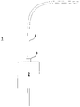
- FIG 1 shows schematically an exemplary embodiment of the sensor arrangement 1 according to the invention, which is used for tracking a vehicle 2 .
- the sensor arrangement 1 has an optical sensor 3, which in the present case is mounted on the front side of the vehicle 2 in such a way that the detection range of the optical sensor 3, in which objects or object structures can be detected, is directed towards a subsurface, which is the roadway for the vehicle 2 is used.
- the subsoil can be formed from a floor of a hall or, in general, of an industrial plant.
- optical track 4 as a further component of the sensor arrangement 1 is arranged on the ground.
- the optical track 4 can be in the form of a tape that is fixed to the substrate, for example by adhesive bonds.
- the Figures 2a and 2b show a first exemplary embodiment of the optical sensor 3 of the sensor arrangement 1 according to FIG figure 1 .
- the optical sensor 3 is designed as a reflection light grid.
- This optical sensor 3 has a linear arrangement of preferably identically designed light sensors, each of which consists of a transmitter 6 emitting transmitted light beams 5 and a receiver 8 receiving received light beams 7 .
- the transmitter 6 can be formed by light-emitting diodes, the receiver by photodiodes.
- the light sensors are integrated in a housing 9 and are connected to an evaluation unit, not shown, which controls the transmitter 6 and evaluates the received signals.
- the evaluation unit can be formed by a microprocessor or the like.
- the longitudinal axis of the optical sensor 3 is oriented transversely to the vehicle direction of the vehicle 2, so that the entire width of the optical track 4 can be detected with it.
- figure 3 12 shows a second exemplary embodiment of the optical sensor 3.
- This optical sensor 3 has an image sensor as the receiver 8, which consists of a matrix-shaped arrangement of receiving elements 8a.
- the image sensor can be in the form of a CMOS or CCD array, for example.
- a linear image sensor can also be provided.
- the optical sensor 3 according to figure 3 in the present case has an illumination unit in the form of a single transmitter 6 emitting transmitted light beams 5 .
- a multiple arrangement of transmitters 6 can also be provided.
- the components of the optical sensor 3 are integrated in a housing 9, in particular also the evaluation unit, which is used to control the transmitter or transmitters 6 and to evaluate the received signals of the receiving elements 8a of the image sensor.
- the optical sensor 3 is designed as a code reader.
- a corresponding decoding unit is implemented in the evaluation unit for this purpose.
- the optical track 4 scanned with the optical sensor 3 generally has a contrast pattern which has intrinsically defined contrast transitions which can be recognized by the optical sensor 3 independently of the remission properties.
- the optical sensor 3 thus continuously detects the optical track 4 while the vehicle 2 is driving, with the optical sensor 3 generating output signals as a function of this, which are fed to the controller of the vehicle 2 for tracking.
- the output signals of the optical sensor 3 can indicate, for example, whether the optical track 4 is detected completely, partially or not at all.
- the optical sensor 3 can also emit output signals that indicate the position of the optical track 4 within the detection range of the optical sensor 3 .
- figure 4 shows an embodiment of the optical track 4, which has a translation-invariant contrast pattern, which is formed by two adjacent strips 10a, 10b, which each extend with a constant width along the longitudinal axis of the optical track 4.
- the strips 10a, 10b forming the contrast pattern generally have a different remission behavior, so that a contrast transition, i.e. an abrupt change in contrast, is obtained along the dividing line of the strips 10a, 10b, which forms an intrinsic contrast pattern that can be detected with the optical sensor 3 can be detected regardless of the nature of the subsoil.
- the strips 10a, 10b can have a very different contrast behavior in that the first strip 10a forms a black area and the second strip 10b forms a white area.
- the strips 10a, 10b can also be formed from different colors.
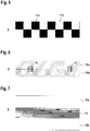
- figure 5 shows an embodiment of the optical track 4, which consists of an alternating sequence of different contrast pattern elements 11a, 11b.
- the first contrast pattern element 11a consists of a white field on a first side of the optical track 4 and a black field of the same area on the second side of the optical track 4.
- the second contrast pattern element 11b consists of a black field on the first side of the optical track 4 and a white field of the same area on the second side of the optical track 4.
- the contrasting pattern elements 11a, 11b thus complement one another to form a chessboard pattern, which can alternatively consist of fields of different colors.
- optical track 4 figure 5 is, as well as that according to the embodiment figure 4 , Given an intrinsic contrast pattern that can be reliably detected regardless of the remission properties of the ground, whereby a safe lane guidance of the vehicle 2 is made possible.
- the optical track 4 according to figure 5 used as an incremental track, in that the contrast pattern elements 11a, 11b of the optical track 4 are continuously determined with the optical sensor 3 as the vehicle 2 travels.
- the optical sensor 3 forms an incremental encoder with the optical track 4 for determining the relative position of the vehicle 2.
- the speed of the vehicle 2 can be determined by evaluating the chronological sequence in the detection of the contrast pattern elements 11a, 11b.
- a slip check can be carried out by controlling the contrast pattern elements 11a, 11b. This is the case when the position of the vehicle 2 is detected by means of an autometry method by detecting the revolutions of the wheels, it being possible for this position detection to be falsified by slippage of the wheels.
- FIG 6 shows an extension of the embodiment of the optical track 4 consisting of the two strips 10a, 10b.
- 4 codes 12 are provided at predetermined positions of the optical track. Their absolute positions can be encoded in the codes 12 so that the absolute position of the vehicle 2 can be determined by reading the codes 12 using the optical sensor 3 .
- tracking information can be encoded in the codes 12, and these can also be programmed specifically for the user. Examples of such tracking information are information about a switch in the optical track 4. A stop for the vehicle 2 can also be encoded with it.
- FIG 7 shows a further embodiment of the optical track 4.
- This optical track 4 has two outer strips 13a, 13b, which can have different contrasts, in particular different colors. Between the strips 13a, 13b there is a code track 14 with a continuous, location-dependent varying code 12, in which position information and/or tracking information can be encoded.
Description
Die Erfindung betrifft eine Sensoranordnung.The invention relates to a sensor arrangement.
Derartige Sensoranordnungen bilden generell optische Spurführungssysteme aus, mittels derer eine kontrollierte Bewegung eines Fahrzeugs entlang einer definierten Bahn bewerkstelligt werden kann. Der optische Sensor ist dabei auf dem Fahrzeug montiert. Mit dem optischen Sensor wird eine sich entlang der Bahn des Fahrzeugs erstreckende Spur erfasst, die insbesondere in Form eines eine bestimmte Farbe aufweisenden Streifens ausgebildet, der auf einem Untergrund, insbesondere der Fahrbahn, auf welcher das Fahrzeug fährt, aufgebracht ist. Durch diese Erfassung der Spur wird das Fahrzeug entlang der vorgegebenen Bahn geführt, indem der optische Sensor während der Fahrt des Fahrzeugs fortlaufend Ausgangssignale generiert, die angeben, ob die Spur erfasst wird oder nicht.Such sensor arrangements generally form optical tracking systems, by means of which a controlled movement of a vehicle along a defined path can be accomplished. The optical sensor is mounted on the vehicle. With the optical sensor, a track extending along the path of the vehicle is detected, which is in particular in the form of a strip having a specific color that is applied to a substrate, in particular the roadway on which the vehicle is driving. By detecting the lane in this way, the vehicle is guided along the predetermined path in that the optical sensor continuously generates output signals while the vehicle is moving, which indicate whether the lane is detected or not.
Je nach Einsatzbereich wird der die Spur bildende Streifen auf einem Hallenboden einer Fabrikhalle oder sogar im Außenbereich einer Industrieanlage aufgebracht, beispielsweise durch Aufkleben des Streifens oder durch Aufsprühen einer entsprechenden Farbe.Depending on the area of use, the strip that forms the track is applied to the floor of a factory building or even to the outside area of an industrial plant, for example by gluing the strip on or by spraying on an appropriate paint.
Ein Problem derartiger Systeme besteht darin, dass in größeren Hallen oder Anlagen der Untergrund hinsichtlich der Beschaffenheit und hinsichtlich der Farbe variieren kann. Dies kann dazu führen, dass sich in einigen Bereichen der Untergrund farblich oder kontrastmäßig nur noch schwach von dem die Spur bildenden Streifen unterscheidet. Dies kann dazu führen, dass die Spur vom optischen Sensor nicht mehr sicher erfasst werden kann, wodurch keine sichere Spurführung des Fahrzeugs mehr möglich ist.A problem with such systems is that in larger halls or facilities, the substrate can vary in terms of texture and color. This can mean that in some areas the background differs only slightly from the stripe forming the track in terms of color or contrast. This can mean that the lane can no longer be reliably detected by the optical sensor, which means that the vehicle can no longer be safely guided in the lane.
Diesem Problem kann prinzipiell dadurch begegnet werden, dass für unterschiedliche Untergründe unterschiedliche Spuren in Form von Streifen ausgewählt werden, deren Farbe einen ausreichenden Kontrast zum Untergrund bildet. Dies ist jedoch äußerst aufwändig.In principle, this problem can be countered by selecting different tracks in the form of strips for different backgrounds, the color of which forms a sufficient contrast to the background. However, this is extremely complex.
Die
Die
Die
Die
Die
Die
Die JP HO480409 A betrifft einen auf einem Fahrzeug installierten Barcodeleser, der auf einer Fahrbahn angeordnete Barcodes liest. In den Barcodes sind Informationen über die Beschaffenheit der Fahrbahn kodiert.JP HO480409 A relates to a vehicle-mounted barcode reader that reads barcodes arranged on a roadway. Information about the condition of the roadway is encoded in the barcodes.
Die
Die
Der Erfindung liegt die Aufgabe zugrunde, eine Sensoranordnung der eingangs genannten Art bereitzustellen, welche bei konstruktiv geringem Aufwand eine hohe Funktionalität aufweist.The invention is based on the object of providing a sensor arrangement of the type mentioned at the outset, which has a high level of functionality with little structural effort.
Zur Lösung dieser Aufgabe sind die Merkmale des Anspruchs 1 vorgesehen. Vorteilhafte Ausführungsformen und zweckmäßige Weiterbildungen der Erfindung sind in den abhängigen Ansprüchen beschrieben.To solve this problem, the features of
Die Erfindung betrifft eine Sensoranordnung mit einem optischen Sensor, welcher an einem Fahrzeug angeordnet ist. Das Fahrzeug wird entlang einer vorgegebenen Bahn bewegt. Die Sensoranordnung weist eine optische Spur auf, die eine Bahnkurve kennzeichnet und auf einem stationären Untergrund aufgebracht ist, welche eine Fahrbahn bildet, auf der das Fahrzeug fährt, wobei die optische Spur ein sich über deren Länge erstreckendes Kontrastmuster aufweist. Der optische Sensor erfasst das Kontrastmuster der optischen Spur während der Fahrt des Fahrzeugs. Der optische Sensor arbeitet nach dem Lichttasterprinzip. In Abhängigkeit von mit dem optischen Sensor generierten Ausgangssignalen ist eine Spurführung des Fahrzeugs durchführbar. Das Kontrastmuster ist in Längsrichtung der optischen Spur translationsinvariant ausgebildet. Durch die Erfassung des Kontrastmusters wird die Winkellage des optischen Sensors relativ zur optischen Spur bestimmt.The invention relates to a sensor arrangement with an optical sensor which is arranged on a vehicle. The vehicle is moved along a predetermined path. The sensor arrangement has an optical track which characterizes a trajectory and is applied to a stationary surface which forms a roadway on which the vehicle travels, the optical track having a contrasting pattern extending along its length. The optical sensor captures the contrast pattern of the optical lane while the vehicle is moving. The optical sensor works according to the light scanner principle. Tracking of the vehicle can be carried out as a function of output signals generated by the optical sensor. The contrast pattern is translation-invariant in the longitudinal direction of the optical track. The angular position of the optical sensor relative to the optical track is determined by detecting the contrast pattern.
Ein wesentlicher Vorteil der Erfindung besteht darin, dass die optische Spur ein intrinsisches Kontrastmuster aufweist, das heißt ein Kontrastmuster, das Kontrastunterschiede innerhalb der Spur ausbildet, die somit vom optischen Sensor sicher erfasst werden können und zwar unabhängig von der Beschaffenheit des Untergrunds, auf welchem die optische Spur aufgebracht ist. Das Kontrastmuster der optischen Spur kann damit unabhängig von den optischen Eigenschaften des Untergrunds, insbesondere unabhängig von dessen Remissionsgrad, vom optischen Sensor sicher erfasst werden.A major advantage of the invention is that the optical track has an intrinsic contrast pattern, i.e. a contrast pattern that forms contrast differences within the track, which can thus be reliably detected by the optical sensor, regardless of the nature of the substrate on which the optical track is applied. The contrast pattern of the optical track can thus be reliably detected by the optical sensor independently of the optical properties of the substrate, in particular independently of its reflectance.
Der optische Sensor generiert dann davon abhängig von der Erfassung der optischen Spur Ausgangssignale, die zur Steuerung des Fahrzeugs verwendet werden können.Depending on the detection of the optical track, the optical sensor then generates output signals that can be used to control the vehicle.
Besonders vorteilhaft ist in Abhängigkeit von mit dem optischen Sensor generierten Ausgangssignalen eine Spurführung des Fahrzeugs durchführbar.Lane guidance of the vehicle can be carried out particularly advantageously as a function of output signals generated by the optical sensor.
Der Untergrund, auf der die optische Spur angebracht ist, ist von der Fahrbahn gebildet, auf der das Fahrzeug fährt. Der optische Sensor ist dann im Bereich der Unterseite des Fahrzeugs so montiert, dass dieser in Abstand oberhalb des Untergrunds angeordnet ist, so dass dieser optische Sensor die optische Spur auf dem Untergrund erfassen kann.The ground on which the optical track is mounted is formed by the roadway on which the vehicle is driving. The optical sensor is then mounted in the area of the underside of the vehicle in such a way that it is arranged at a distance above the ground, so that this optical sensor can detect the optical track on the ground.
Je nach Ausbildung des Fahrzeugs und der Umgebung des Fahrzeugs, kann der Untergrund auch von einer Hallendecke oder dergleichen gebildet sein. Dann kann der optische Sensor an der Oberseite des Fahrzeugs angeordnet sein, um die optische Spur zu erfassen.Depending on the design of the vehicle and the environment of the vehicle, the subsoil can also be formed by a hall ceiling or the like. Then the optical sensor can be arranged at the top of the vehicle to detect the optical lane.
Erfindungsgemäß ist das Kontrastmuster in Längsrichtung der optischen Spur translationsinvariant ausgebildet.According to the invention, the contrast pattern is translation-invariant in the longitudinal direction of the optical track.
Das Kontrastmuster ist damit in Längsrichtung der optischen Spur translationsinvariant ausgebildet. Eine derartige optische Spur ist äußerst einfach aufgebaut und kann dementsprechend einfach hergestellt werden.The contrast pattern is thus formed in a translation-invariant manner in the longitudinal direction of the optical track. Such an optical track has an extremely simple structure and can accordingly be easily manufactured.
Ein Beispiel für eine derartige optische Spur ist, dass das Kontrastmuster von zwei nebeneinander liegenden, sich in Längsrichtung der optischen Spur erstreckenden Streifen mit unterschiedlichen Remissionen gebildet ist.An example of such an optical track is that the contrast pattern is formed by two strips with different remissions lying next to one another and extending in the longitudinal direction of the optical track.
Dieses Kontrastmuster weist eine besonders einfache Struktur auf. Durch die beiden in Längsrichtung der optischen Spur verlaufenden Streifen mit unterschiedlichen Remissionen wird am Übergang zwischen den beiden Streifen ein Kontrastunterschied erhalten, der mit dem optischen Sensor einfach und sicher erfasst werden kann. Wesentlich dabei ist, dass dieser Kontrastunterschied nicht an einem der längsseitigen Ränder der optischen Spur, sondern in deren zentralen Bereich liegt. Damit wirken sich Einflüsse der Remission des Untergrunds, unabhängig ob dieser stark oder schwach reflektierend ist, bei der Detektion des Übergangs zwischen den zwei Streifen nicht störend aus, so dass das Kontrastmuster unabhängig von der Beschaffenheit des Untergrunds sicher erfasst werden kann.This contrast pattern has a particularly simple structure. Due to the two strips running in the longitudinal direction of the optical track with different remissions, a Contrast difference obtained, which can be easily and reliably detected with the optical sensor. It is essential that this difference in contrast is not on one of the longitudinal edges of the optical track, but in its central area. This means that influences from the remission of the background, regardless of whether it is strongly or weakly reflective, do not have a disruptive effect on the detection of the transition between the two strips, so that the contrast pattern can be reliably detected regardless of the nature of the background.
Generell weist das Kontrastmuster der optischen Spur ein Kontrastmuster aus, das im inneren Bereich der optischen Spur Kontrastunterschiede ausbildet, die dann mit dem optischen Sensor unabhängig vom Untergrund erfasst werden können.In general, the contrast pattern of the optical track has a contrast pattern that forms contrast differences in the inner area of the optical track, which can then be detected with the optical sensor regardless of the background.
Schließlich ist durch die Erfassung des Kontrastmusters die Winkellage des optischen Sensors relativ zur optischen Spur bestimmt.Finally, the angular position of the optical sensor relative to the optical track is determined by detecting the contrast pattern.
Durch die Erfassung des Kontrastmusters wird mit dem optischen Sensor fortlaufend dessen Winkellage zur optischen Spur, das heißt der Winkel zwischen einer Achse des optischen Sensors zur Achse der optischen Spur bestimmt. Da der optische Sensor fest mit dem Fahrzeug verbunden ist, wird dadurch der aktuelle Winkel zwischen der Achse des Fahrzeugs und der optischen Spur bestimmt. Bei Kurvenfahrten oder bei Wiederanfahren des Fahrzeugs, zum Beispiel nach einem Stromausfall, liefert diese Winkelinformation eine wichtige Zusatzinformation für die Steuerung des Fahrzeugs, beispielsweise um den Lenkeinschlag des Fahrzeugs zu optimieren. Befindet sich beispielsweise die optische Spur in der Mitte des Fahrzeugs beziehungsweise des optischen Sensors, wird jedoch ein von 90° abweichender Winkel zwischen optischem Sensor und optischer Spur detektiert, kann die Lenkung des Fahrzeugs so eingeschlagen werden, dass bei einer Weiterfahrt des Fahrzeugs eine Vergrößerung der Abweichung von der optischen Spur vermieden wird.By detecting the contrast pattern, its angular position relative to the optical track, ie the angle between an axis of the optical sensor and the axis of the optical track, is continuously determined with the optical sensor. Since the optical sensor is permanently connected to the vehicle, it determines the current angle between the vehicle's axis and the optical track. When cornering or when the vehicle starts moving again, for example after a power failure, this angle information provides important additional information for controlling the vehicle, for example to optimize the steering angle of the vehicle. For example, if the optical track is in the middle of the vehicle or the optical sensor, but an angle deviating from 90° is detected between the optical sensor and the optical track, the vehicle can be steered in such a way that when the vehicle continues to drive, the Deviation from the optical track is avoided.
Die Funktionalität der erfindungsgemäßen Sensoranordnung kann dadurch erweitert werden, dass auf der optischen Spur Codes angebracht sind, welche mittels des optischen Sensors gelesen werden.The functionality of the sensor arrangement according to the invention can be expanded by applying codes to the optical track, which are read by means of the optical sensor.
Durch Lesen der Codes können weitere Informationen für die Steuerung des Fahrzeugs gewonnen werden.By reading the codes, further information for controlling the vehicle can be obtained.
Typischerweise wird bei dem Fahrzeug dessen Position nach der Methode der Autometrie bestimmt, das heißt es wird aus der Anzahl der Umdrehungen der Räder die Fahrzeugposition bestimmt. Bei Auftreten eines Schlupfs der Räder ist diese Positionsbestimmung fehlerhaft. Durch eine fortlaufende Erfassung der Kontrastmusterelemente des Kontrastmusters der optischen Spur kann eine Schlupfkontrolle durchgeführt werden, das heißt die Fehler der Positionsbestimmung aufgrund des vorhandenen Schlupfs können korrigiert werden.Typically, the position of the vehicle is determined using the autometry method, ie the vehicle position is determined from the number of revolutions of the wheels. If the wheels slip, this determination of position is incorrect. A slip check can be carried out by continuously detecting the contrast pattern elements of the contrast pattern of the optical track, ie the errors in the position determination due to the existing slip can be corrected.
Erfindungsgemäß wird durch die Erfassung des Kontrastmusters die Winkellage des optischen Sensors relativ zur optischen Spur bestimmt.According to the invention, the angular position of the optical sensor relative to the optical track is determined by detecting the contrast pattern.
Durch die Erfassung des Kontrastmusters wird mit dem optischen Sensor fortlaufend dessen Winkellage zur optischen Spur, das heißt der Winkel zwischen einer Achse des optischen Sensors zur Achse der optischen Spur bestimmt. Da der optische Sensor fest mit dem Fahrzeug verbunden ist, wird dadurch der aktuelle Winkel zwischen der Achse des Fahrzeugs und der optischen Spur bestimmt. Bei Kurvenfahrten oder bei Wiederanfahren des Fahrzeugs, zum Beispiel nach einem Stromausfall, liefert diese Winkelinformation eine wichtige Zusatzinformation für die Steuerung des Fahrzeugs, beispielsweise um den Lenkeinschlag des Fahrzeugs zu optimieren. Befindet sich beispielsweise die optische Spur in der Mitte des Fahrzeugs beziehungsweise des optischen Sensors, wird jedoch ein von 90° abweichender Winkel zwischen optischem Sensor und optischer Spur detektiert, kann die Lenkung des Fahrzeugs so eingeschlagen werden, dass bei einer Weiterfahrt des Fahrzeugs eine Vergrößerung der Abweichung von der optischen Spur vermieden wird.By detecting the contrast pattern, its angular position relative to the optical track, ie the angle between an axis of the optical sensor and the axis of the optical track, is continuously determined with the optical sensor. Since the optical sensor is permanently connected to the vehicle, it determines the current angle between the vehicle's axis and the optical track. When cornering or when the vehicle starts moving again, for example after a power failure, this angle information provides important additional information for controlling the vehicle, for example to optimize the steering angle of the vehicle. If, for example, the optical track is in the middle of the vehicle or the optical sensor, but an angle deviating from 90° is detected between the optical sensor and the optical track, the vehicle can be steered in such a way that when the vehicle continues to drive, the Deviation from the optical track is avoided.
Die Funktionalität der erfindungsgemäßen Sensoranordnung kann dadurch erweitert werden, dass auf der optischen Spur Codes angebracht sind, welche mittels des optischen Sensors gelesen werden.The functionality of the sensor arrangement according to the invention can be expanded by applying codes to the optical track, which are read by means of the optical sensor.
Durch Lesen der Codes können weitere Informationen für die Steuerung des Fahrzeugs gewonnen werden.By reading the codes, further information for controlling the vehicle can be obtained.
Gemäß einer ersten Ausgestaltung sind in den Codes Positionsinformationen kodiert.According to a first embodiment, position information is encoded in the codes.
Diese Positionsinformationen können insbesondere die Absolutpositionen des aufgebrachten Codes enthalten, so dass durch Lesen der Codes eine Bestimmung der Absolutposition des Fahrzeugs möglich ist.This position information can in particular contain the absolute positions of the applied code, so that the absolute position of the vehicle can be determined by reading the code.
Alternativ oder zusätzlich können in den Codes Spurführungsinformationen kodiert sein.Alternatively or additionally, tracking information can be encoded in the codes.
Derartige Spurinformationen können Informationen derart enthalten, dass sie eine Weiche oder Haltestelle für das Fahrzeug kodieren. Auch können die Codes frei programmiert werden, um so Zusatzinformationen über die Spurführung des Fahrzeugs vorzugeben.Such lane information can contain information such that it encodes a switch or stop for the vehicle. The codes can also be freely programmed in order to specify additional information about the lane guidance of the vehicle.
Der optische Sensor arbeitet generell nach dem Lichttasterprinzip und weist hierfür wenigstens einen Sendelichtstrahlen emittierenden Sender und wenigstens einen Empfangslichtstrahlen empfangenden Empfänger auf. Generell ist der optische Sensor dabei derart ausgebildet, dass mit diesem ortsaufgelöst Kontrastunterschiede erfasst werden können, so dass mit diesem die Kontrastmuster der optischen Spur erfasst werden können.The optical sensor generally works according to the light scanner principle and for this purpose has at least one transmitter emitting transmitted light beams and at least one receiver receiving received light beams. In general, the optical sensor is designed in such a way that spatially resolved contrast differences can be detected with it, so that the contrast pattern of the optical track can be detected with it.
Gemäß einer ersten Ausgestaltung ist der optische Sensor als Reflexionslichtgitter ausgebildet, das heißt der optische Sensor weist eine Linearanordnung mehrerer Lichttaster mit jeweils einem Sendelichtstrahlen emittierenden Sender und einem Empfangslichtstrahlen empfangenden Empfänger auf.According to a first embodiment, the optical sensor is designed as a reflection light grid, ie the optical sensor has a linear arrangement of several light sensors each with a transmitter emitting transmitted light beams and a receiver receiving received light beams.
Gemäß einer alternativen Ausgestaltung weist der optische Sensor als Empfänger einen Bildsensor auf, der in Form einer zeilen- oder matrixförmigen Anordnung von Empfangselementen ausgebildet ist. Insbesondere in dieser Ausgestaltung kann der optische Sensor als Codeleser ausgebildet sein, um auf der optischen Spur angeordnete Codes erfassen können.According to an alternative embodiment, the optical sensor has an image sensor as the receiver, which is designed in the form of a linear or matrix-shaped arrangement of receiving elements. In this embodiment in particular, the optical sensor can be designed as a code reader in order to be able to detect codes arranged on the optical track.
Die Erfindung wird im Folgenden anhand der Zeichnungen erläutert. Es zeigen:
- Figur 1:
- Schematische Darstellung der erfindungsgemäßen Sensoranordnung zur Spurführung eines Fahrzeugs.
- Figur 2:
- Erstes Ausführungsbeispiel des optischen Sensors der Sensoranordnung gemäß
Figur 1- a) Draufsicht
- b) Querschnittsdarstellung
- Figur 3:
- Zweites Ausführungsbeispiel des optischen Sensors der Sensoranordnung gemäß
Figur 1 - Figur 4:
- Erstes Ausführungsbeispiel einer optischen Spur für die
Sensoranordnung gemäß Figur 1 . - Figur 5:
- Zweites Ausführungsbeispiel einer optischen Spur für die
Sensoranordnung gemäß Figur 1 . - Figur 6:
- Drittes Ausführungsbeispiel einer optischen Spur für die
Sensoranordnung gemäß Figur 1 . - Figur 7:
- Viertes Ausführungsbeispiel einer optischen Spur für die
Sensoranordnung gemäß Figur 1 .
- Figure 1:
- Schematic representation of the sensor arrangement according to the invention for tracking a vehicle.
- Figure 2:
- First exemplary embodiment of the optical sensor according to the sensor arrangement
figure 1 .- a) top view
- b) cross-sectional representation
- Figure 3:
- Second exemplary embodiment of the optical sensor according to the sensor arrangement
figure 1 . - Figure 4:
- First embodiment of an optical track for the sensor arrangement according to
figure 1 . - Figure 5:
- Second exemplary embodiment of an optical track for the sensor arrangement according to FIG
figure 1 . - Figure 6:
- Third exemplary embodiment of an optical track for the sensor arrangement according to FIG
figure 1 . - Figure 7:
- Fourth exemplary embodiment of an optical track for the sensor arrangement according to FIG
figure 1 .
Auf dem Untergrund ist eine optische Spur 4 als weiteres Bestandteil der Sensoranordnung 1 angeordnet. Die optische Spur 4 kann in Form eines Bands ausgebildet sein, das auf dem Untergrund fixiert wird, beispielsweise durch Klebeverbindungen.An
Die
Zur Detektion der optischen Spur 4, insbesondere der dort enthaltenen intrinsischen Kontrastmuster, ist die Längsachse des optischen Sensors 3 quer zur Fahrzeugrichtung des Fahrzeugs 2 orientiert, so dass mit diesem die gesamte Breite der optischen Spur 4 erfasst werden kann.To detect the
Alternativ kann auch ein zeilenförmiger Bildsensor vorgesehen sein.Alternatively, a linear image sensor can also be provided.
Der optische Sensor 3 gemäß
Analog zur Ausführungsform der
Insbesondere in der Ausführungsform gemäß
Die mit dem optischen Sensor 3 abgetastete optische Spur 4 weist generell ein Kontrastmuster auf, das intrinsisch definierte Kontrastübergänge aufweist, die mittels des optischen Sensors 3 unabhängig von den Remissionseigenschaften erkannt werden können.The
Mit dem optischen Sensor 3 erfolgt somit fortlaufend während der Fahrt des Fahrzeugs 2 eine ortsaufgelöste Erfassung der optischen Spur 4, wobei in Abhängigkeit hiervon der optische Sensor 3 Ausgangssignale generiert, die der Steuerung des Fahrzeugs 2 für eine Spurführung zugeführt werden. Die Ausgangssignale des optischen Sensors 3 können beispielsweise angeben, ob die optische Spur 4 vollständig, teilweise oder gar nicht erfasst wird. Prinzipiell kann der optische Sensor 3 auch Ausgangssignale ausgeben, die die Lage der optischen Spur 4 innerhalb des Erfassungsbereichs des optischen Sensors 3 angeben.The
Die
Die das Kontrastmuster bildenden Streifen 10a, 10b weisen generell ein unterschiedliches Remissionsverhalten auf, so dass entlang der Trennlinie der Streifen 10a, 10b ein Kontrastübergang, das heißt ein abrupter Wechsel des Kontrasts erhalten wird, der ein intrinsisches Kontrastmuster ausbildet, das mit dem optischen Sensor 3 unabhängig von der Beschaffenheit des Untergrunds erfasst werden kann. Die Streifen 10a, 10b können ein stark unterschiedliches Kontrastverhalten aufweisen, in dem der erste Streifen 10a eine schwarze Fläche und der zweite Streifen 10b eine weiße Fläche ausbildet. Auch können die Streifen 10a, 10b aus unterschiedlichen Farben gebildet sein.The
Das erste Kontrastmusterelement 11a besteht aus einem weißen Feld auf einer ersten Seite der optischen Spur 4 und einem flächengleichem schwarzen Feld auf der zweiten Seite der optischen Spur 4.The first
Das zweite Kontrastmusterelement 11b besteht aus einem schwarzen Feld auf der ersten Seite der optischen Spur 4 und einem flächengleichen weißen Feld auf der zweiten Seite der optischen Spur 4.The second
Somit ergänzen sich die Kontrastmusterelemente 11a, 11b zu einem Schachbrettmuster, das alternativ aus Feldern unterschiedlicher Farbe bestehen kann.The
Auch bei der optischen Spur 4 gemäß
Weiterhin wird die optische Spur 4 gemäß
Durch die Auswertung der zeitlichen Abfolge bei der Detektion der Kontrastmusterelemente 11a, 11b kann außerdem die Geschwindigkeit des Fahrzeugs 2 bestimmt werden.In addition, the speed of the
Schließlich kann durch eine Steuerung der Kontrastmusterelemente 11a, 11b eine Schlupfkontrolle durchgeführt werden. Dies ist dann der Fall, wenn mittels eines Autometrieverfahrens durch die Erfassung der Umdrehungen der Räder die Position des Fahrzeugs 2 erfasst wird, wobei diese Positionserfassung durch einen Schlupf der Räder verfälscht sein kann.Finally, a slip check can be carried out by controlling the
- (1)(1)
- Sensoranordnungsensor arrangement
- (2)(2)
- Fahrzeugvehicle
- (3)(3)
- Optischer Sensoroptical sensor
- (4)(4)
- Optische Spuroptical track
- (5)(5)
- Sendelichtstrahlentransmission light rays
- (6)(6)
- SenderChannel
- (7)(7)
- Empfangslichtstrahlenreceiving light beams
- (8)(8th)
- Empfängerrecipient
- (8a)(8a)
- Empfangselementereceiving elements
- (9)(9)
- GehäuseHousing
- (10a)(10a)
- Streifenstripes
- (10b)(10b)
- Streifenstripes
- (11a)(11a)
- Kontrastmusterelementcontrast pattern element
- (11b)(11b)
- Kontrastmusterelementcontrast pattern element
- (12)(12)
- Codecode
- (13a)(13a)
- Streifenstripes
- (13b)(13b)
- Streifenstripes
- (14)(14)
- Codespurcode track
Claims (7)
- Sensor arrangement (1) with an optical sensor (3), which can be arranged at a vehicle (2) moved along a predetermined path, wherein the sensor arrangement comprises an optical track which characterises a path curve and can be mounted on a stationary substrate, which forms a travel path on which the vehicle travels, wherein the optical track (3) has a contrast pattern extending over the length thereof and wherein the optical sensor (3) is suitable for the purpose of detecting the contrast pattern of the optical track (4) during travel of the vehicle (2) and wherein the optical sensor (3) operates in accordance with the light scanning principle, wherein track guidance of the vehicle (2) can be performed in dependence on output signals generated by the optical sensor (3) and wherein the contrast pattern is formed to be translation-invariant in the longitudinal direction of the optical track (4), characterised in that the sensor arrangement (1) is suitable for the purpose of determining the angular position of the optical sensor (3) relative to the optical track (4) through detection of the contrast pattern.
- Sensor arrangement (1) according to claim 1, characterised in that the contrast pattern is formed by two mutually adjacent strips (10a, 10b), which extend in the longitudinal direction of the optical track (4), with different diffuse reflectivities.
- Sensor arrangement (1) according to one of claims 1 and 2, characterised in that codes (12) which are read by means of the optical sensor (3) are applied to the optical track (4).
- Sensor arrangement (1) according to claim 3, characterised in that positional data are coded in the codes (12).
- Sensor arrangement (1) according to one of claims 3 and 4, characterised in that the track guidance data are coded in the codes (12).
- Sensor arrangement (1) according to any one of claims 1 to 5, characterised in that the optical sensor (3) comprises an image sensor or the optical sensor (3) is constructed in the form of a reflection light grating.
- Sensor arrangement (1) according to any one of claims 1 to 6, characterised in that the optical sensor (3) is a code reader.
Priority Applications (1)
| Application Number | Priority Date | Filing Date | Title |
|---|---|---|---|
| EP19151358.9A EP3680624B1 (en) | 2019-01-11 | 2019-01-11 | Sensor assembly |
Applications Claiming Priority (1)
| Application Number | Priority Date | Filing Date | Title |
|---|---|---|---|
| EP19151358.9A EP3680624B1 (en) | 2019-01-11 | 2019-01-11 | Sensor assembly |
Publications (2)
| Publication Number | Publication Date |
|---|---|
| EP3680624A1 EP3680624A1 (en) | 2020-07-15 |
| EP3680624B1 true EP3680624B1 (en) | 2022-09-07 |
Family
ID=65019366
Family Applications (1)
| Application Number | Title | Priority Date | Filing Date |
|---|---|---|---|
| EP19151358.9A Active EP3680624B1 (en) | 2019-01-11 | 2019-01-11 | Sensor assembly |
Country Status (1)
| Country | Link |
|---|---|
| EP (1) | EP3680624B1 (en) |
Citations (14)
| Publication number | Priority date | Publication date | Assignee | Title |
|---|---|---|---|---|
| US2996137A (en) * | 1958-01-29 | 1961-08-15 | Chu Yaohan | Automatic radar guided and computer controlled vehicles |
| JPH0480409A (en) * | 1990-07-23 | 1992-03-13 | Komatsu Ltd | Marking on road and detection method thereof |
| DE10013767A1 (en) | 2000-03-20 | 2001-10-11 | Rosenheimer Foerderanlage | Electric transport vehicles surface transport system with supply-and control-system for contactless power transmission, has flush-mounted rail system for track-guidance and contactless inductive power supply |
| EP1345031A2 (en) | 2002-03-16 | 2003-09-17 | Leuze electronic GmbH + Co. | Optoelectronic device |
| EP1621504A1 (en) | 2004-07-27 | 2006-02-01 | ThyssenKrupp Aufzüge GmbH | Measuring strip and system for determining the motion of a moving object |
| DE102005047658A1 (en) | 2005-10-05 | 2007-04-12 | Leuze Electronic Gmbh + Co. Kg | Dimensional device for detecting marks for a vehicle position's dimensions has a position-dimensioning system formed by an arrangement of marks and an optical sensor to detect the marks |
| EP1867542A1 (en) | 2006-06-13 | 2007-12-19 | Robert Bosch Gmbh | Lane keeping assistant with lane change function |
| EP2037227A1 (en) | 2007-09-12 | 2009-03-18 | Pepperl + Fuchs Gmbh | Method and device for determining the position of a vehicle |
| DE112011103834T5 (en) | 2010-11-19 | 2013-09-05 | Magna Electronics, Inc. | Lane departure warning and lane centering |
| US20140368837A1 (en) * | 2012-02-20 | 2014-12-18 | Korea Railroad Research Institute | Absolute position detection system |
| DE202014100689U1 (en) * | 2014-02-17 | 2015-06-01 | Sick Ag | Optoelectronic device for position determination |
| DE112014003434T5 (en) | 2013-07-23 | 2016-05-04 | Toyota Jidosha Kabushiki Kaisha | Lane departure warning device |
| EP3270114A1 (en) | 2016-07-15 | 2018-01-17 | Leuze electronic GmbH + Co KG | Sensor assembly |
| EP3282286A1 (en) | 2016-08-08 | 2018-02-14 | Leuze electronic GmbH + Co KG | Optical sensor |
-
2019
- 2019-01-11 EP EP19151358.9A patent/EP3680624B1/en active Active
Patent Citations (14)
| Publication number | Priority date | Publication date | Assignee | Title |
|---|---|---|---|---|
| US2996137A (en) * | 1958-01-29 | 1961-08-15 | Chu Yaohan | Automatic radar guided and computer controlled vehicles |
| JPH0480409A (en) * | 1990-07-23 | 1992-03-13 | Komatsu Ltd | Marking on road and detection method thereof |
| DE10013767A1 (en) | 2000-03-20 | 2001-10-11 | Rosenheimer Foerderanlage | Electric transport vehicles surface transport system with supply-and control-system for contactless power transmission, has flush-mounted rail system for track-guidance and contactless inductive power supply |
| EP1345031A2 (en) | 2002-03-16 | 2003-09-17 | Leuze electronic GmbH + Co. | Optoelectronic device |
| EP1621504A1 (en) | 2004-07-27 | 2006-02-01 | ThyssenKrupp Aufzüge GmbH | Measuring strip and system for determining the motion of a moving object |
| DE102005047658A1 (en) | 2005-10-05 | 2007-04-12 | Leuze Electronic Gmbh + Co. Kg | Dimensional device for detecting marks for a vehicle position's dimensions has a position-dimensioning system formed by an arrangement of marks and an optical sensor to detect the marks |
| EP1867542A1 (en) | 2006-06-13 | 2007-12-19 | Robert Bosch Gmbh | Lane keeping assistant with lane change function |
| EP2037227A1 (en) | 2007-09-12 | 2009-03-18 | Pepperl + Fuchs Gmbh | Method and device for determining the position of a vehicle |
| DE112011103834T5 (en) | 2010-11-19 | 2013-09-05 | Magna Electronics, Inc. | Lane departure warning and lane centering |
| US20140368837A1 (en) * | 2012-02-20 | 2014-12-18 | Korea Railroad Research Institute | Absolute position detection system |
| DE112014003434T5 (en) | 2013-07-23 | 2016-05-04 | Toyota Jidosha Kabushiki Kaisha | Lane departure warning device |
| DE202014100689U1 (en) * | 2014-02-17 | 2015-06-01 | Sick Ag | Optoelectronic device for position determination |
| EP3270114A1 (en) | 2016-07-15 | 2018-01-17 | Leuze electronic GmbH + Co KG | Sensor assembly |
| EP3282286A1 (en) | 2016-08-08 | 2018-02-14 | Leuze electronic GmbH + Co KG | Optical sensor |
Non-Patent Citations (6)
| Title |
|---|
| ANONYMOUS: "Handbuch PGV...-F200/-F200A...-B16-V15 Auflicht-Positioniersystem", PEPPERL+FUCHS, 30 September 2016 (2016-09-30), XP093116036, [retrieved on 20240104] |
| ANONYMOUS: "Handbuch PGV...-F200/-F200A...-B6-V15B Auflicht-Positioniersystem", PEPPERL+FUCHS, 30 April 2015 (2015-04-30), XP093116037, [retrieved on 20240104] |
| ANONYMOUS: "HG G-73840 Optical Line Tracker – Auswerter für 2 Kameras, CANopen® / seriell / parallel Port", GÖTTING, 9 December 2020 (2020-12-09), XP093116041, Retrieved from the Internet <URL:https://www.goetting.de/komponenten/73840> [retrieved on 20240104] |
| ANONYMOUS: "Optical Line Tracker — Auswerter für 2 Kameras — CANopen® — seriell — parallel Port HG G-73840ZC", GÖTTING KG, 2 November 2016 (2016-11-02), XP093116039, Retrieved from the Internet <URL:https://www.goetting.de/dateien/downloads/HG_G-73840ZC_D_geraetebeschreibung_R16_TD.pdf> [retrieved on 20240104] |
| PEPPERLFUCHSUSA: "PGV – Automated Guided Vehicle Control AGV", YOUTUBE, XP093116043, Retrieved from the Internet <URL:https://www.youtube.com/watch?v=dDK496dhgds> [retrieved on 20240104] |
| PEPPERLFUCHSUSA: "Position Guided Vision Optimal for Automatic Guided Vehicles", YOUTUBE, XP093116045, Retrieved from the Internet <URL:https://www.youtube.com/watch?v=5tyEDJUTKME> [retrieved on 20240104] |
Also Published As
| Publication number | Publication date |
|---|---|
| EP3680624A1 (en) | 2020-07-15 |
Similar Documents
| Publication | Publication Date | Title |
|---|---|---|
| DE19910933B4 (en) | Device for positioning a vehicle | |
| EP0555507B1 (en) | Position measuring apparatus | |
| WO2011101115A2 (en) | Roadway-integrated radar sensor | |
| DE102007043460B4 (en) | Method for navigating a vehicle | |
| DE102017117162A1 (en) | Sensor and method for detection and distance determination of objects | |
| DE10211779B4 (en) | Optoelectronic device | |
| DE102005047658B4 (en) | Device for determining position | |
| EP3680624B1 (en) | Sensor assembly | |
| EP3809157B1 (en) | Distance-measuring optoelectronic sensor and method for detecting a target object | |
| WO2008034742A2 (en) | Method and system for determining the position and orientation of an unmanned vehicle as well as corresponding vehicle | |
| DE102005055905A1 (en) | Length measuring arrangement for use in e.g. vehicle position sensor, has encoder with magnetic field that symmetrically runs between arrangements, where field line run has variation with respect to measuring direction over measuring area | |
| EP1770375B1 (en) | Position measuring device with two scales whose coded tracks overlap one another | |
| WO2004059341A1 (en) | Method for detecting environmental information and for determining the position of a parking space | |
| EP3510461B1 (en) | Method and system for position capture | |
| DE102007045181A1 (en) | Moved object i.e. steering wheel, linear movement or rotation angle detecting device for motor vehicle, has microwave radar with transmitter and receiver that are present in sensor arrangement for scanning surface structures | |
| DE102008032786A1 (en) | Device for determining position of vehicle, is mobile along course in direction of motion, and has optical position mark reader for line-wise scanning from position marks | |
| EP1742022A1 (en) | Position detection on a rod | |
| EP1637493B1 (en) | Elevator system with a device for determining the position of an elevator cabin and method to operate the elevator system | |
| DE19508397C2 (en) | Optoelectronic device for recognizing marks | |
| DE202005012194U1 (en) | Position and distance detection device has component in light path between light source and sensor movable relative to source and/or sensor that varies light property of light detected by sensor depending on its relative movement | |
| EP3348967B1 (en) | Optoelectronic position detection device and method for position detection | |
| EP0973013B1 (en) | Displacement sensor | |
| DE102018208327A1 (en) | System and method for determining the position of a vehicle for automated driving on a terrain | |
| WO2008071167A2 (en) | Determination of the position of an object using a sensor | |
| DE10225546B4 (en) | Optoelectronic device |
Legal Events
| Date | Code | Title | Description |
|---|---|---|---|
| PUAI | Public reference made under article 153(3) epc to a published international application that has entered the european phase |
Free format text: ORIGINAL CODE: 0009012 |
|
| STAA | Information on the status of an ep patent application or granted ep patent |
Free format text: STATUS: REQUEST FOR EXAMINATION WAS MADE |
|
| 17P | Request for examination filed |
Effective date: 20190925 |
|
| AK | Designated contracting states |
Kind code of ref document: A1 Designated state(s): AL AT BE BG CH CY CZ DE DK EE ES FI FR GB GR HR HU IE IS IT LI LT LU LV MC MK MT NL NO PL PT RO RS SE SI SK SM TR |
|
| AX | Request for extension of the european patent |
Extension state: BA ME |
|
| STAA | Information on the status of an ep patent application or granted ep patent |
Free format text: STATUS: EXAMINATION IS IN PROGRESS |
|
| 17Q | First examination report despatched |
Effective date: 20210223 |
|
| GRAP | Despatch of communication of intention to grant a patent |
Free format text: ORIGINAL CODE: EPIDOSNIGR1 |
|
| STAA | Information on the status of an ep patent application or granted ep patent |
Free format text: STATUS: GRANT OF PATENT IS INTENDED |
|
| RIC1 | Information provided on ipc code assigned before grant |
Ipc: B61L 25/02 20060101ALI20220513BHEP Ipc: B61L 23/04 20060101ALI20220513BHEP Ipc: G01D 5/249 20060101ALI20220513BHEP Ipc: G01D 5/245 20060101AFI20220513BHEP |
|
| INTG | Intention to grant announced |
Effective date: 20220531 |
|
| GRAS | Grant fee paid |
Free format text: ORIGINAL CODE: EPIDOSNIGR3 |
|
| GRAA | (expected) grant |
Free format text: ORIGINAL CODE: 0009210 |
|
| STAA | Information on the status of an ep patent application or granted ep patent |
Free format text: STATUS: THE PATENT HAS BEEN GRANTED |
|
| AK | Designated contracting states |
Kind code of ref document: B1 Designated state(s): AL AT BE BG CH CY CZ DE DK EE ES FI FR GB GR HR HU IE IS IT LI LT LU LV MC MK MT NL NO PL PT RO RS SE SI SK SM TR |
|
| REG | Reference to a national code |
Ref country code: GB Ref legal event code: FG4D Free format text: NOT ENGLISH |
|
| REG | Reference to a national code |
Ref country code: CH Ref legal event code: EP Ref country code: AT Ref legal event code: REF Ref document number: 1517407 Country of ref document: AT Kind code of ref document: T Effective date: 20220915 |
|
| REG | Reference to a national code |
Ref country code: DE Ref legal event code: R096 Ref document number: 502019005526 Country of ref document: DE |
|
| REG | Reference to a national code |
Ref country code: IE Ref legal event code: FG4D Free format text: LANGUAGE OF EP DOCUMENT: GERMAN |
|
| REG | Reference to a national code |
Ref country code: LT Ref legal event code: MG9D |
|
| REG | Reference to a national code |
Ref country code: NL Ref legal event code: MP Effective date: 20220907 |
|
| PG25 | Lapsed in a contracting state [announced via postgrant information from national office to epo] |
Ref country code: SE Free format text: LAPSE BECAUSE OF FAILURE TO SUBMIT A TRANSLATION OF THE DESCRIPTION OR TO PAY THE FEE WITHIN THE PRESCRIBED TIME-LIMIT Effective date: 20220907 Ref country code: RS Free format text: LAPSE BECAUSE OF FAILURE TO SUBMIT A TRANSLATION OF THE DESCRIPTION OR TO PAY THE FEE WITHIN THE PRESCRIBED TIME-LIMIT Effective date: 20220907 Ref country code: NO Free format text: LAPSE BECAUSE OF FAILURE TO SUBMIT A TRANSLATION OF THE DESCRIPTION OR TO PAY THE FEE WITHIN THE PRESCRIBED TIME-LIMIT Effective date: 20221207 Ref country code: LV Free format text: LAPSE BECAUSE OF FAILURE TO SUBMIT A TRANSLATION OF THE DESCRIPTION OR TO PAY THE FEE WITHIN THE PRESCRIBED TIME-LIMIT Effective date: 20220907 Ref country code: LT Free format text: LAPSE BECAUSE OF FAILURE TO SUBMIT A TRANSLATION OF THE DESCRIPTION OR TO PAY THE FEE WITHIN THE PRESCRIBED TIME-LIMIT Effective date: 20220907 Ref country code: FI Free format text: LAPSE BECAUSE OF FAILURE TO SUBMIT A TRANSLATION OF THE DESCRIPTION OR TO PAY THE FEE WITHIN THE PRESCRIBED TIME-LIMIT Effective date: 20220907 |
|
| PG25 | Lapsed in a contracting state [announced via postgrant information from national office to epo] |
Ref country code: HR Free format text: LAPSE BECAUSE OF FAILURE TO SUBMIT A TRANSLATION OF THE DESCRIPTION OR TO PAY THE FEE WITHIN THE PRESCRIBED TIME-LIMIT Effective date: 20220907 Ref country code: GR Free format text: LAPSE BECAUSE OF FAILURE TO SUBMIT A TRANSLATION OF THE DESCRIPTION OR TO PAY THE FEE WITHIN THE PRESCRIBED TIME-LIMIT Effective date: 20221208 |
|
| PG25 | Lapsed in a contracting state [announced via postgrant information from national office to epo] |
Ref country code: SM Free format text: LAPSE BECAUSE OF FAILURE TO SUBMIT A TRANSLATION OF THE DESCRIPTION OR TO PAY THE FEE WITHIN THE PRESCRIBED TIME-LIMIT Effective date: 20220907 Ref country code: RO Free format text: LAPSE BECAUSE OF FAILURE TO SUBMIT A TRANSLATION OF THE DESCRIPTION OR TO PAY THE FEE WITHIN THE PRESCRIBED TIME-LIMIT Effective date: 20220907 Ref country code: PT Free format text: LAPSE BECAUSE OF FAILURE TO SUBMIT A TRANSLATION OF THE DESCRIPTION OR TO PAY THE FEE WITHIN THE PRESCRIBED TIME-LIMIT Effective date: 20230109 Ref country code: ES Free format text: LAPSE BECAUSE OF FAILURE TO SUBMIT A TRANSLATION OF THE DESCRIPTION OR TO PAY THE FEE WITHIN THE PRESCRIBED TIME-LIMIT Effective date: 20220907 Ref country code: CZ Free format text: LAPSE BECAUSE OF FAILURE TO SUBMIT A TRANSLATION OF THE DESCRIPTION OR TO PAY THE FEE WITHIN THE PRESCRIBED TIME-LIMIT Effective date: 20220907 |
|
| PG25 | Lapsed in a contracting state [announced via postgrant information from national office to epo] |
Ref country code: SK Free format text: LAPSE BECAUSE OF FAILURE TO SUBMIT A TRANSLATION OF THE DESCRIPTION OR TO PAY THE FEE WITHIN THE PRESCRIBED TIME-LIMIT Effective date: 20220907 Ref country code: PL Free format text: LAPSE BECAUSE OF FAILURE TO SUBMIT A TRANSLATION OF THE DESCRIPTION OR TO PAY THE FEE WITHIN THE PRESCRIBED TIME-LIMIT Effective date: 20220907 Ref country code: IS Free format text: LAPSE BECAUSE OF FAILURE TO SUBMIT A TRANSLATION OF THE DESCRIPTION OR TO PAY THE FEE WITHIN THE PRESCRIBED TIME-LIMIT Effective date: 20230107 Ref country code: EE Free format text: LAPSE BECAUSE OF FAILURE TO SUBMIT A TRANSLATION OF THE DESCRIPTION OR TO PAY THE FEE WITHIN THE PRESCRIBED TIME-LIMIT Effective date: 20220907 |
|
| PGFP | Annual fee paid to national office [announced via postgrant information from national office to epo] |
Ref country code: DE Payment date: 20230112 Year of fee payment: 5 |
|
| REG | Reference to a national code |
Ref country code: DE Ref legal event code: R026 Ref document number: 502019005526 Country of ref document: DE |
|
| PLBI | Opposition filed |
Free format text: ORIGINAL CODE: 0009260 |
|
| PLAX | Notice of opposition and request to file observation + time limit sent |
Free format text: ORIGINAL CODE: EPIDOSNOBS2 |
|
| PG25 | Lapsed in a contracting state [announced via postgrant information from national office to epo] |
Ref country code: NL Free format text: LAPSE BECAUSE OF FAILURE TO SUBMIT A TRANSLATION OF THE DESCRIPTION OR TO PAY THE FEE WITHIN THE PRESCRIBED TIME-LIMIT Effective date: 20220907 Ref country code: AL Free format text: LAPSE BECAUSE OF FAILURE TO SUBMIT A TRANSLATION OF THE DESCRIPTION OR TO PAY THE FEE WITHIN THE PRESCRIBED TIME-LIMIT Effective date: 20220907 |
|
| 26 | Opposition filed |
Opponent name: PEPPERL+FUCHS SE Effective date: 20230607 |
|
| PG25 | Lapsed in a contracting state [announced via postgrant information from national office to epo] |
Ref country code: DK Free format text: LAPSE BECAUSE OF FAILURE TO SUBMIT A TRANSLATION OF THE DESCRIPTION OR TO PAY THE FEE WITHIN THE PRESCRIBED TIME-LIMIT Effective date: 20220907 |
|
| PG25 | Lapsed in a contracting state [announced via postgrant information from national office to epo] |
Ref country code: SI Free format text: LAPSE BECAUSE OF FAILURE TO SUBMIT A TRANSLATION OF THE DESCRIPTION OR TO PAY THE FEE WITHIN THE PRESCRIBED TIME-LIMIT Effective date: 20220907 |
|
| REG | Reference to a national code |
Ref country code: CH Ref legal event code: PL |
|
| GBPC | Gb: european patent ceased through non-payment of renewal fee |
Effective date: 20230111 |
|
| PG25 | Lapsed in a contracting state [announced via postgrant information from national office to epo] |
Ref country code: LU Free format text: LAPSE BECAUSE OF NON-PAYMENT OF DUE FEES Effective date: 20230111 |
|
| REG | Reference to a national code |
Ref country code: BE Ref legal event code: MM Effective date: 20230131 |
|
| PLBB | Reply of patent proprietor to notice(s) of opposition received |
Free format text: ORIGINAL CODE: EPIDOSNOBS3 |
|
| PG25 | Lapsed in a contracting state [announced via postgrant information from national office to epo] |
Ref country code: LI Free format text: LAPSE BECAUSE OF NON-PAYMENT OF DUE FEES Effective date: 20230131 Ref country code: GB Free format text: LAPSE BECAUSE OF NON-PAYMENT OF DUE FEES Effective date: 20230111 Ref country code: CH Free format text: LAPSE BECAUSE OF NON-PAYMENT OF DUE FEES Effective date: 20230131 |
|
| PG25 | Lapsed in a contracting state [announced via postgrant information from national office to epo] |
Ref country code: FR Free format text: LAPSE BECAUSE OF NON-PAYMENT OF DUE FEES Effective date: 20230131 Ref country code: BE Free format text: LAPSE BECAUSE OF NON-PAYMENT OF DUE FEES Effective date: 20230131 |
|
| PG25 | Lapsed in a contracting state [announced via postgrant information from national office to epo] |
Ref country code: IE Free format text: LAPSE BECAUSE OF NON-PAYMENT OF DUE FEES Effective date: 20230111 |