EP3680560B1 - Cooker hood - Google Patents
Cooker hood Download PDFInfo
- Publication number
- EP3680560B1 EP3680560B1 EP19216876.3A EP19216876A EP3680560B1 EP 3680560 B1 EP3680560 B1 EP 3680560B1 EP 19216876 A EP19216876 A EP 19216876A EP 3680560 B1 EP3680560 B1 EP 3680560B1
- Authority
- EP
- European Patent Office
- Prior art keywords
- smoke deflector
- lighting apparatus
- state
- cooker hood
- disposed
- Prior art date
- Legal status (The legal status is an assumption and is not a legal conclusion. Google has not performed a legal analysis and makes no representation as to the accuracy of the status listed.)
- Active
Links
Images
Classifications
-
- F—MECHANICAL ENGINEERING; LIGHTING; HEATING; WEAPONS; BLASTING
- F24—HEATING; RANGES; VENTILATING
- F24C—DOMESTIC STOVES OR RANGES ; DETAILS OF DOMESTIC STOVES OR RANGES, OF GENERAL APPLICATION
- F24C15/00—Details
- F24C15/20—Removing cooking fumes
- F24C15/2064—Removing cooking fumes illumination for cooking hood
-
- F—MECHANICAL ENGINEERING; LIGHTING; HEATING; WEAPONS; BLASTING
- F21—LIGHTING
- F21V—FUNCTIONAL FEATURES OR DETAILS OF LIGHTING DEVICES OR SYSTEMS THEREOF; STRUCTURAL COMBINATIONS OF LIGHTING DEVICES WITH OTHER ARTICLES, NOT OTHERWISE PROVIDED FOR
- F21V33/00—Structural combinations of lighting devices with other articles, not otherwise provided for
- F21V33/0004—Personal or domestic articles
- F21V33/0044—Household appliances, e.g. washing machines or vacuum cleaners
-
- F—MECHANICAL ENGINEERING; LIGHTING; HEATING; WEAPONS; BLASTING
- F21—LIGHTING
- F21V—FUNCTIONAL FEATURES OR DETAILS OF LIGHTING DEVICES OR SYSTEMS THEREOF; STRUCTURAL COMBINATIONS OF LIGHTING DEVICES WITH OTHER ARTICLES, NOT OTHERWISE PROVIDED FOR
- F21V7/00—Reflectors for light sources
Definitions
- the present application relates to the field of cooker hoods.
- An existing cooker hood is generally provided with a lighting apparatus, where the lighting apparatus is configured to project light to a cooking area.
- the lighting mode lacks variety.
- the light emitted by the lighting apparatus of the existing cooker hood is directly projected to the cooking area, and is easy to directly enter human eyes, causing discomfort.
- the light emitted by the lighting apparatus of the existing cooker hood is generally not soft enough.
- the light emitted by the lighting apparatus of the existing cooker hood is difficult to be evenly distributed in the cooking area.
- An objective of the embodiments of the present application is to provide an improved cooker hood.
- An embodiment of the present application relates to a cooker hood, including a lighting apparatus, and further including a light reflection member with the features of claim 1.
- the light reflection member is disposed to be suitable for reflecting light emitted by the lighting apparatus.
- the light reflection member is disposed to be suitable for reflecting light emitted by the lighting apparatus to be used for illumination or creating a specific atmosphere. In this way, this helps prevent the light emitted by the lighting apparatus from being directly entering human eyes.
- the light reflection member is a reflective structural member attached to a component of the cooker hood.
- the reflective structural member is a mirror reflection member or a diffuse reflection member.
- the light reflection member is a reflective layer attached to a component of the cooker hood.
- the reflective layer includes a reflective film or a reflective coating or a reflective metal layer.
- the cooker hood is an inclined cooker hood, including an air inlet and a smoke deflector.
- the light reflection member is disposed on an inner wall of the smoke deflector.
- the smoke deflector is disposed to be suitable for switching between a first state and a second state. When the smoke deflector is in the first state, the smoke deflector seals the air inlet. When the smoke deflector is in the second state, a bottom end of the smoke deflector rotates outward to form an eaves, and the light reflection member is disposed to be suitable for reflecting the light emitted by the lighting apparatus. When the smoke deflector is in the second state, the light reflection member is disposed to be suitable for reflecting the light emitted by the lighting apparatus to be used for illumination or creating a specific atmosphere.
- the lighting apparatus is disposed on edges at both sides of the air inlet.
- the smoke deflector When the smoke deflector is in the first state, the smoke deflector shields the lighting apparatus.
- a light transmissive surface of the lighting apparatus faces the inner wall of the smoke deflector.
- the smoke deflector When the smoke deflector is in the second state, the light emitted by the lighting apparatus passes through the light transmissive surface of the lighting apparatus to project onto the inner wall of the smoke deflector.
- the smoke deflector when the smoke deflector is in the second state, the smoke deflector shields the lighting apparatus in a horizontal direction.
- the lighting apparatus is set to be brightness adjustable.
- the cooker hood is an inclined cooker hood, including an air inlet and a glass smoke deflector.
- An outer surface of the glass smoke deflector is plated with a metal reflective film.
- the glass smoke deflector is disposed to be suitable for switching between a first state and a second state. When the glass smoke deflector is in the first state, the glass smoke deflector seals the air inlet. When the glass smoke deflector is in the second state, a bottom end of the glass smoke deflector rotates outward to form an eaves, and the glass smoke deflector is disposed to be suitable for reflecting light emitted by the lighting apparatus to be used for illumination.
- an inner wall of the metal smoke deflector is equivalent to a mirror surface.
- the inner wall of the metal smoke deflector is suitable for reflecting the light emitted by the lighting apparatus.
- the inner wall of the metal smoke deflector is suitable for reflecting the light emitted by the lighting apparatus to be used for illumination or creating a specific atmosphere. In this way, this helps prevent the light emitted by the lighting apparatus from being directly entering human eyes.
- Still another embodiment of the present application relates to a cooker hood, including a lighting apparatus.
- the cooker hood is an inclined cooker hood, including an air inlet and a metal smoke deflector.
- the metal smoke deflector is disposed to be suitable for switching between a first state and a second state. When the metal smoke deflector is in the first state, the metal smoke deflector seals the air inlet. When the metal smoke deflector is in the second state, a bottom end of the metal smoke deflector rotates outward to form an eaves.
- a light transmissive surface of the lighting apparatus faces an inner wall of the smoke deflector, and light emitted by the lighting apparatus passes through the light transmissive surface of the lighting apparatus to project onto the inner wall of the metal smoke deflector and is reflected by the inner wall of the metal smoke deflector.
- the metal smoke deflector is in the second state, the light emitted by the lighting apparatus passes through the light transmissive surface of the lighting apparatus to project onto the inner wall of the metal smoke deflector and is reflected by the inner wall of the metal smoke deflector to be used for illumination or creating a specific atmosphere. In this way, this helps prevent the light emitted by the lighting apparatus from being directly entering human eyes.
- first and second appearing this specification are merely intended for the purpose of description, and are not intended to indicate relative importance.
- the terms are not intended to define the quantity of defined features.
- the terms are not intended to define a logical relationship or a sequence relationship of defined features.
- the cooker hood is an inclined cooker hood, including a lighting apparatus 1, a light reflection member, an air inlet, a smoke deflector 2, a control panel 3, an oil deflector 4, a filter 5, an oil cup 6, an upper housing member 7, a lower housing member 8, and a blower.
- the blower (not shown in the figure) is disposed in the lower housing member 8.
- the filter 5 is disposed at the air inlet.
- the control panel 3, the smoke deflector 2, the oil deflector 4, and the oil cup 6 are successively disposed on the lower housing member 8 from top to bottom.
- the oil cup 6 is located at the bottom of the inclined cooker hood.
- the light reflection member is disposed to be suitable for reflecting light emitted by the lighting apparatus 1 to be used for illumination.
- the light reflection member is a reflective layer attached to a component of the cooker hood, where the reflective layer is a reflective film.
- the light reflection member is disposed on an inner wall of the smoke deflector 2.
- the reflective layer is attached to the inner wall of the smoke deflector 2 of the cooker hood.
- the smoke deflector 2 is disposed to be suitable for switching between a first state and a second state.
- the smoke deflector 2 When the smoke deflector 2 is in the first state, the smoke deflector 2 seals the air inlet.
- a bottom end of the smoke deflector 2 rotates outward to form an eaves (to be specific, when the smoke deflector 2 switches from the first state to the second state, the bottom end of the smoke deflector 2 rotates outward, so that the smoke deflector 2 forms the eaves when the smoke deflector 2 is in the second state), as shown in FIG. 1 and FIG. 2 .
- the light reflection member is disposed to be suitable for reflecting the light emitted by the lighting apparatus 1 to be used for illumination. Because the light is reflected by the light reflection member, the light for immolation is relatively soft. In addition, because the light is reflected by the light reflection member, the light for illumination is more evenly distributed in a cooking area.
- the lighting apparatus 1 is the only component for illumination in this embodiment of the cooker hood.
- the lighting apparatus 1 includes two lighting lamps, where the two lighting lamps are disposed on edges at both sides of the air inlet respectively. As shown in FIG. 1 (only the lighting lamp on the edge at the right side of the air inlet is shown in the figure), the filter 5 is disposed between the two lighting lamps.
- An LED light source is preferably used as the lighting lamp, and each lighting lamp may be provided with one or several LED light sources. Each lighting lamp may alternatively be a lamp strip composed of a plurality of LED light sources.
- the smoke deflector 2 When the smoke deflector 2 is in the first state, the smoke deflector 2 shields the lighting apparatus 1. In this case, the lighting apparatus is not suitable for illumination, and the lighting apparatus 1 is turned off.
- the bottom end of the smoke deflector 2 When the smoke deflector 2 is in the second state, the bottom end of the smoke deflector 2 is connected to a top end of the oil deflector 4, and a top end of the smoke deflector 2 is connected to a bottom end of the control panel 3.
- the control panel 3, the smoke deflector 2, and the oil deflector 4 are successively connected from top to bottom, and are all disposed obliquely, and outer surfaces of the three are in the same plane.
- a light transmissive surface of the lighting apparatus 1 faces the inner wall of the smoke deflector 2.
- the light transmissive surface of the lighting apparatus 1 is made of light transmissive glass.
- FIG. 2 indicates a direction of the light emitted by the lighting apparatus 1, where a light path along which the light emitted by the lighting apparatus 1 passing through the light transmissive surface of the lighting apparatus 1 to project onto the inner wall of the smoke deflector 2 is shown by the arrow in FIG. 2 .
- the smoke deflector 2 When the smoke deflector 2 is in the second state, the smoke deflector 2 shields the lighting apparatus 1 in a horizontal direction.
- the lighting apparatus 1 is set to be brightness adjustable. When the brightness of the lighting apparatus 1 is reduced to some extent, a specific atmosphere may also be created. It can be seen that functions of the lighting apparatus 1 may be optionally switched between being used for illumination and being used for creating a specific atmosphere.
- the blower may be disposed in the upper housing member.
- the blower may be partially disposed in the upper housing member, and partially disposed in the lower housing member.
- the light reflection member may alternatively be a mirror reflection member, namely, a mirror suitable for reflecting light.
- the mirror reflection member with a mirror reflection member facing outward, is fixedly attached to the inner wall of the smoke deflector.
- the light reflection member may alternatively be a diffuse reflection member.
- the diffuse reflection member, with a diffuse reflection surface facing outward is fixedly attached to the inner wall of the smoke deflector.
- the reflective layer may be a reflective coating or a reflective metal layer.
- the reflective metal layer may be a metal sheet suitable for reflecting light, and may be fixedly attached to the inner wall of the smoke deflector.
- a specific location of the lighting apparatus is not limited in this embodiment either, and may alternatively be other possible locations, for example, an air inlet area, an upper side of the air inlet, or a lower side of the air inlet.
- the invention further provides a cooker hood, where the cooker hood is an inclined cooker hood, including a lighting apparatus, an air inlet and a glass smoke deflector.
- the glass smoke deflector is disposed to be suitable for switching between a first state and a second state. When the glass smoke deflector is in the first state, the glass smoke deflector seals the air inlet. When the glass smoke deflector is in the second state, a bottom end of the glass smoke deflector rotates outward to form an eaves.
- An outer surface of the glass smoke deflector is plated with a metal reflective film. In this way, the glass smoke deflector forms a mirror, and an inner wall of the glass smoke deflector is a reflective surface of the glass smoke deflector.
- the inner wall of the glass smoke deflector and the outer surface of the glass smoke deflector are located at inner and outer sides of the glass smoke deflector respectively.
- the inner wall of the glass smoke deflector is disposed to be suitable for reflecting light emitted by the lighting apparatus to be used for illumination.
- the present application further provides still another embodiment of a cooker hood, not covered by the claims, where the cooker hood is an inclined cooker hood, including a lighting apparatus, an air inlet and a metal smoke deflector.
- the metal smoke deflector is disposed to be suitable for switching between a first state and a second state. When the metal smoke deflector is in the first state, the metal smoke deflector seals the air inlet. When the metal smoke deflector is in the second state, a bottom end of the metal smoke deflector rotates outward to form an eaves.
- a light transmissive surface of the lighting apparatus faces an inner wall of the smoke deflector, and light emitted by the lighting apparatus passes through the light transmissive surface of the lighting apparatus to project onto the inner wall of the metal smoke deflector and is reflected by the inner wall of the metal smoke deflector to be used for illumination. Because the light transmissive surface of the lighting apparatus faces the inner wall of the smoke deflector, the light emitted by the lighting apparatus passes through the light transmissive surface of the lighting apparatus to directly project onto the inner wall of the metal smoke deflector. To improve reflective performance of the inner wall of the metal smoke deflector, the inner wall of the metal smoke deflector is polished.
Landscapes
- Engineering & Computer Science (AREA)
- General Engineering & Computer Science (AREA)
- Chemical & Material Sciences (AREA)
- Combustion & Propulsion (AREA)
- Mechanical Engineering (AREA)
- Non-Portable Lighting Devices Or Systems Thereof (AREA)
- Arrangement Of Elements, Cooling, Sealing, Or The Like Of Lighting Devices (AREA)
- Planar Illumination Modules (AREA)
- Ventilation (AREA)
Description
- The present application relates to the field of cooker hoods.
-
DE 10 2015 107 048 A1 ,EP 2 428 737 A1CN206669830U andCN203964090U disclose range hoods with lighting devices. - An existing cooker hood is generally provided with a lighting apparatus, where the lighting apparatus is configured to project light to a cooking area. The lighting mode lacks variety. In addition, the light emitted by the lighting apparatus of the existing cooker hood is directly projected to the cooking area, and is easy to directly enter human eyes, causing discomfort. Besides, the light emitted by the lighting apparatus of the existing cooker hood is generally not soft enough. In addition, the light emitted by the lighting apparatus of the existing cooker hood is difficult to be evenly distributed in the cooking area.
- An objective of the embodiments of the present application is to provide an improved cooker hood.
- An embodiment of the present application relates to a cooker hood, including a lighting apparatus, and further including a light reflection member with the features of
claim 1. The light reflection member is disposed to be suitable for reflecting light emitted by the lighting apparatus. The light reflection member is disposed to be suitable for reflecting light emitted by the lighting apparatus to be used for illumination or creating a specific atmosphere. In this way, this helps prevent the light emitted by the lighting apparatus from being directly entering human eyes. - In a possible embodiment, the light reflection member is a reflective structural member attached to a component of the cooker hood. The reflective structural member is a mirror reflection member or a diffuse reflection member.
- In a possible embodiment, the light reflection member is a reflective layer attached to a component of the cooker hood.
- In a possible embodiment, the reflective layer includes a reflective film or a reflective coating or a reflective metal layer.
- According to the invention, the cooker hood is an inclined cooker hood, including an air inlet and a smoke deflector. The light reflection member is disposed on an inner wall of the smoke deflector. The smoke deflector is disposed to be suitable for switching between a first state and a second state. When the smoke deflector is in the first state, the smoke deflector seals the air inlet. When the smoke deflector is in the second state, a bottom end of the smoke deflector rotates outward to form an eaves, and the light reflection member is disposed to be suitable for reflecting the light emitted by the lighting apparatus. When the smoke deflector is in the second state, the light reflection member is disposed to be suitable for reflecting the light emitted by the lighting apparatus to be used for illumination or creating a specific atmosphere.
- In a possible embodiment, the lighting apparatus is disposed on edges at both sides of the air inlet. When the smoke deflector is in the first state, the smoke deflector shields the lighting apparatus.
- When the smoke deflector is in the second state, a light transmissive surface of the lighting apparatus faces the inner wall of the smoke deflector.
- When the smoke deflector is in the second state, the light emitted by the lighting apparatus passes through the light transmissive surface of the lighting apparatus to project onto the inner wall of the smoke deflector.
- In a possible embodiment, when the smoke deflector is in the second state, the smoke deflector shields the lighting apparatus in a horizontal direction.
- In a possible embodiment, the lighting apparatus is set to be brightness adjustable.
- Another embodiment of the present application relates to a cooker hood, including a lighting apparatus. The cooker hood is an inclined cooker hood, including an air inlet and a glass smoke deflector. An outer surface of the glass smoke deflector is plated with a metal reflective film. The glass smoke deflector is disposed to be suitable for switching between a first state and a second state. When the glass smoke deflector is in the first state, the glass smoke deflector seals the air inlet. When the glass smoke deflector is in the second state, a bottom end of the glass smoke deflector rotates outward to form an eaves, and the glass smoke deflector is disposed to be suitable for reflecting light emitted by the lighting apparatus to be used for illumination. Because the outer surface of the glass smoke deflector is plated with the metal reflective film, an inner wall of the metal smoke deflector is equivalent to a mirror surface. When the glass smoke deflector is in the second state, the inner wall of the metal smoke deflector is suitable for reflecting the light emitted by the lighting apparatus. When the smoke deflector is in the second state, the inner wall of the metal smoke deflector is suitable for reflecting the light emitted by the lighting apparatus to be used for illumination or creating a specific atmosphere. In this way, this helps prevent the light emitted by the lighting apparatus from being directly entering human eyes.
- Still another embodiment of the present application, not covered by the claims, relates to a cooker hood, including a lighting apparatus. The cooker hood is an inclined cooker hood, including an air inlet and a metal smoke deflector. The metal smoke deflector is disposed to be suitable for switching between a first state and a second state. When the metal smoke deflector is in the first state, the metal smoke deflector seals the air inlet. When the metal smoke deflector is in the second state, a bottom end of the metal smoke deflector rotates outward to form an eaves. In this case, a light transmissive surface of the lighting apparatus faces an inner wall of the smoke deflector, and light emitted by the lighting apparatus passes through the light transmissive surface of the lighting apparatus to project onto the inner wall of the metal smoke deflector and is reflected by the inner wall of the metal smoke deflector. When the metal smoke deflector is in the second state, the light emitted by the lighting apparatus passes through the light transmissive surface of the lighting apparatus to project onto the inner wall of the metal smoke deflector and is reflected by the inner wall of the metal smoke deflector to be used for illumination or creating a specific atmosphere. In this way, this helps prevent the light emitted by the lighting apparatus from being directly entering human eyes.
- Herein, it should be noted that the directional expressions such as "bottom end", "top end", "horizontal direction", "top-down", "below" and the like appearing in the present application are based on the usual use state of the cooker hood unless otherwise specified particularly.
- Herein, it should be noted that the terms "first" and "second" appearing this specification are merely intended for the purpose of description, and are not intended to indicate relative importance. In addition, the terms are not intended to define the quantity of defined features. In addition, the terms are not intended to define a logical relationship or a sequence relationship of defined features.
- The foregoing technical solutions in the present application are not intended to describe all possible embodiments of the present application.
- The following accompanying drawings are merely used for describing and explaining the present application by using examples, and are not intended to limit the scope of the present application, where:
-
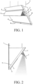
FIG. 1 is a schematic structural diagram of an embodiment of a cooker hood according to the present application; and -
FIG. 2 is another schematic structural diagram of an embodiment of a cooker hood according to the present application. - 1. lighting apparatus; 2. smoke deflector; 3. control panel; 4. oil deflector; 5. filter; 6. oil cup; 7. upper housing member; 8. lower housing member.
- To make the objectives, solutions, and beneficial effects of the present application clearer, the present application is further described below with reference to the accompanying drawings and preferred embodiments.
- The present application provides an embodiment of a cooker hood. As shown in
FIG. 1 and FIG. 2 , the cooker hood is an inclined cooker hood, including alighting apparatus 1, a light reflection member, an air inlet, asmoke deflector 2, acontrol panel 3, anoil deflector 4, afilter 5, anoil cup 6, anupper housing member 7, alower housing member 8, and a blower. The blower (not shown in the figure) is disposed in thelower housing member 8. Thefilter 5 is disposed at the air inlet. Thecontrol panel 3, thesmoke deflector 2, theoil deflector 4, and theoil cup 6 are successively disposed on thelower housing member 8 from top to bottom. Theoil cup 6 is located at the bottom of the inclined cooker hood. - The light reflection member is disposed to be suitable for reflecting light emitted by the
lighting apparatus 1 to be used for illumination. The light reflection member is a reflective layer attached to a component of the cooker hood, where the reflective layer is a reflective film. Specifically, the light reflection member is disposed on an inner wall of thesmoke deflector 2. In other words, the reflective layer is attached to the inner wall of thesmoke deflector 2 of the cooker hood. - The
smoke deflector 2 is disposed to be suitable for switching between a first state and a second state. When thesmoke deflector 2 is in the first state, thesmoke deflector 2 seals the air inlet. When thesmoke deflector 2 is in the second state, a bottom end of thesmoke deflector 2 rotates outward to form an eaves (to be specific, when thesmoke deflector 2 switches from the first state to the second state, the bottom end of thesmoke deflector 2 rotates outward, so that thesmoke deflector 2 forms the eaves when thesmoke deflector 2 is in the second state), as shown inFIG. 1 and FIG. 2 . When thesmoke deflector 2 is in the second state, the light reflection member is disposed to be suitable for reflecting the light emitted by thelighting apparatus 1 to be used for illumination. Because the light is reflected by the light reflection member, the light for immolation is relatively soft. In addition, because the light is reflected by the light reflection member, the light for illumination is more evenly distributed in a cooking area. - The
lighting apparatus 1 is the only component for illumination in this embodiment of the cooker hood. Thelighting apparatus 1 includes two lighting lamps, where the two lighting lamps are disposed on edges at both sides of the air inlet respectively. As shown inFIG. 1 (only the lighting lamp on the edge at the right side of the air inlet is shown in the figure), thefilter 5 is disposed between the two lighting lamps. An LED light source is preferably used as the lighting lamp, and each lighting lamp may be provided with one or several LED light sources. Each lighting lamp may alternatively be a lamp strip composed of a plurality of LED light sources. - When the
smoke deflector 2 is in the first state, thesmoke deflector 2 shields thelighting apparatus 1. In this case, the lighting apparatus is not suitable for illumination, and thelighting apparatus 1 is turned off. When thesmoke deflector 2 is in the second state, the bottom end of thesmoke deflector 2 is connected to a top end of theoil deflector 4, and a top end of thesmoke deflector 2 is connected to a bottom end of thecontrol panel 3. In this case, thecontrol panel 3, thesmoke deflector 2, and theoil deflector 4 are successively connected from top to bottom, and are all disposed obliquely, and outer surfaces of the three are in the same plane. - When the
smoke deflector 2 is in the second state, a light transmissive surface of thelighting apparatus 1 faces the inner wall of thesmoke deflector 2. The light transmissive surface of thelighting apparatus 1 is made of light transmissive glass. When thesmoke deflector 2 is in the second state, the light emitted by thelighting apparatus 1 passes through the light transmissive surface of thelighting apparatus 1 to project onto the inner wall of thesmoke deflector 2, and the light projected onto the inner wall of thesmoke deflector 2 is reflected by the reflective layer and projected onto the cooking area below the cooker hood. A shaded area inFIG. 2 indicates a direction of the light emitted by thelighting apparatus 1, where a light path along which the light emitted by thelighting apparatus 1 passing through the light transmissive surface of thelighting apparatus 1 to project onto the inner wall of thesmoke deflector 2 is shown by the arrow inFIG. 2 . - When the
smoke deflector 2 is in the second state, thesmoke deflector 2 shields thelighting apparatus 1 in a horizontal direction. To be specific, when a user stands in front of the cooker hood and looks towards thesmoke deflector 2 in the horizontal direction, and the user cannot see thelighting apparatus 1 due to the shielding of thesmoke deflector 2. Thelighting apparatus 1 is set to be brightness adjustable. When the brightness of thelighting apparatus 1 is reduced to some extent, a specific atmosphere may also be created. It can be seen that functions of thelighting apparatus 1 may be optionally switched between being used for illumination and being used for creating a specific atmosphere. - For example, alternatively, the blower may be disposed in the upper housing member. For another example, alternatively, the blower may be partially disposed in the upper housing member, and partially disposed in the lower housing member. For another example, the light reflection member may alternatively be a mirror reflection member, namely, a mirror suitable for reflecting light. Specifically, the mirror reflection member, with a mirror reflection member facing outward, is fixedly attached to the inner wall of the smoke deflector. For another example, the light reflection member may alternatively be a diffuse reflection member. Specifically, the diffuse reflection member, with a diffuse reflection surface facing outward, is fixedly attached to the inner wall of the smoke deflector. For another example, alternatively, the reflective layer may be a reflective coating or a reflective metal layer. The reflective metal layer may be a metal sheet suitable for reflecting light, and may be fixedly attached to the inner wall of the smoke deflector. For another example, a specific location of the lighting apparatus is not limited in this embodiment either, and may alternatively be other possible locations, for example, an air inlet area, an upper side of the air inlet, or a lower side of the air inlet.
- The invention further provides a cooker hood, where the cooker hood is an inclined cooker hood, including a lighting apparatus, an air inlet and a glass smoke deflector. The glass smoke deflector is disposed to be suitable for switching between a first state and a second state. When the glass smoke deflector is in the first state, the glass smoke deflector seals the air inlet. When the glass smoke deflector is in the second state, a bottom end of the glass smoke deflector rotates outward to form an eaves. An outer surface of the glass smoke deflector is plated with a metal reflective film. In this way, the glass smoke deflector forms a mirror, and an inner wall of the glass smoke deflector is a reflective surface of the glass smoke deflector. The inner wall of the glass smoke deflector and the outer surface of the glass smoke deflector are located at inner and outer sides of the glass smoke deflector respectively. When the glass smoke deflector is in the second state, the inner wall of the glass smoke deflector is disposed to be suitable for reflecting light emitted by the lighting apparatus to be used for illumination. For the specific structure of the cooker hood in this embodiment, refer to the structures shown in
FIG. 1 and FIG. 2 , and details are not described herein again. - The present application further provides still another embodiment of a cooker hood, not covered by the claims, where the cooker hood is an inclined cooker hood, including a lighting apparatus, an air inlet and a metal smoke deflector. The metal smoke deflector is disposed to be suitable for switching between a first state and a second state. When the metal smoke deflector is in the first state, the metal smoke deflector seals the air inlet. When the metal smoke deflector is in the second state, a bottom end of the metal smoke deflector rotates outward to form an eaves. In this case, a light transmissive surface of the lighting apparatus faces an inner wall of the smoke deflector, and light emitted by the lighting apparatus passes through the light transmissive surface of the lighting apparatus to project onto the inner wall of the metal smoke deflector and is reflected by the inner wall of the metal smoke deflector to be used for illumination. Because the light transmissive surface of the lighting apparatus faces the inner wall of the smoke deflector, the light emitted by the lighting apparatus passes through the light transmissive surface of the lighting apparatus to directly project onto the inner wall of the metal smoke deflector. To improve reflective performance of the inner wall of the metal smoke deflector, the inner wall of the metal smoke deflector is polished. For the specific structure of the cooker hood in this embodiment, refer to the structures shown in
FIG. 1 and FIG. 2 , and details are not described herein again. - It should be additionally noted that the present application should not be understood as being limited to the implementations described above, but should be interpreted as covering all possible implementations that are determined by the claims of the present application with reference to the content disclosed in the specification.
Claims (10)
- A cooker hood, comprising a lighting apparatus (1), wherein:the cooker hood further comprises a light reflection member;the light reflection member is disposed to be suitable for reflecting light emitted bythe lighting apparatus (1); andthe cooker hood is an inclined cooker hood, comprising an air inlet and a smoke deflector (2), wherein the smoke deflector (2) is disposed to be suitable for switching between a first state and a second state;when the smoke deflector is in the first state, the smoke deflector (2) seals the air inlet;when the smoke deflector is in the second state, a light transmissive surface of the lighting apparatus (1) faces an inner wall of the smoke deflector (2);characterized in that :the light reflection member is disposed on an inner wall of the smoke deflector (2); andwhen the smoke deflector (2) is in the second state, a bottom end of the smoke deflector (2) rotates outward to form an eaves, and the light reflection member is disposed to be suitable for reflecting the light emitted by the lighting apparatus (1) through the light transmissive surface.
- The cooker hood according to claim 1, characterized in that:the light reflection member is a reflective structural member attached to a component of the cooker hood; andthe reflective structural member is a mirror reflection member or a diffuse reflection member.
- The cooker hood according to claim 1, characterized in that:
the light reflection member is a reflective layer attached to a component of the cooker hood. - The cooker hood according to claim 3, characterized in that:
the reflective layer comprises a reflective film or a reflective coating or a reflective metal layer. - The cooker hood according to claim 1, characterized in that:the lighting apparatus (1) is disposed on edges at both sides of the air inlet; andwhen the smoke deflector (2) is in the first state, the smoke deflector (2) shields the lighting apparatus (1).
- The cooker hood according to claim 1, characterized in that:
when the smoke deflector (2) is in the second state, a light transmissive surface of the lighting apparatus (1) faces the inner wall of the smoke deflector (2). - The cooker hood according to claim 6, characterized in that:
when the smoke deflector (2) is in the second state, the light emitted by the lighting apparatus (1) passes through the light transmissive surface of the lighting apparatus of the lighting apparatus to project onto the inner wall of the smoke deflector (2). - The cooker hood according to claim 1, characterized in that:
when the smoke deflector (2) is in the second state, the smoke deflector (2) shields the lighting apparatus (1) in a horizontal direction. - The cooker hood according to claim 1, characterized in that:
the lighting apparatus (1) is set to be brightness adjustable. - A cooker hood, comprising a lighting apparatus, wherein:the cooker hood is an inclined cooker hood, comprising an air inlet and a smoke deflector;the smoke deflector is disposed to be suitable for switching between a first state and a second state;when the smoke deflector is in the first state, the smoke deflector seals the air inlet; andwhen the smoke deflector is in the second state, a light transmissive surface of the lighting apparatus (1) faces an inner wall of the smoke deflector (2), characterized in that:the smoke deflector is a glass smoke deflector;an outer surface of the glass smoke deflector is plated with a metal reflective film;andwhen the glass smoke deflector is in the second state, a bottom end of the glass smoke deflector rotates outward to form an eaves, and the glass smoke deflector is disposed to be suitable for reflecting light emitted by the lighting apparatus through the light transmissive surface.
Applications Claiming Priority (1)
| Application Number | Priority Date | Filing Date | Title |
|---|---|---|---|
| CN201920033370.3U CN210320196U (en) | 2019-01-09 | 2019-01-09 | Smoke exhaust ventilator |
Publications (2)
| Publication Number | Publication Date |
|---|---|
| EP3680560A1 EP3680560A1 (en) | 2020-07-15 |
| EP3680560B1 true EP3680560B1 (en) | 2023-08-02 |
Family
ID=68944154
Family Applications (1)
| Application Number | Title | Priority Date | Filing Date |
|---|---|---|---|
| EP19216876.3A Active EP3680560B1 (en) | 2019-01-09 | 2019-12-17 | Cooker hood |
Country Status (2)
| Country | Link |
|---|---|
| EP (1) | EP3680560B1 (en) |
| CN (1) | CN210320196U (en) |
Cited By (1)
| Publication number | Priority date | Publication date | Assignee | Title |
|---|---|---|---|---|
| US12629733B2 (en) | 2020-05-12 | 2026-05-19 | BSH Hausgeräte GmbH | Extractor hood and method for operating an extractor hood |
Families Citing this family (4)
| Publication number | Priority date | Publication date | Assignee | Title |
|---|---|---|---|---|
| DE102020205974A1 (en) * | 2020-05-12 | 2021-12-02 | BSH Hausgeräte GmbH | Extractor hood and method for operating an extractor hood |
| CN116685884A (en) * | 2020-08-15 | 2023-09-01 | 胡方明 | secondary mirror |
| US11333346B1 (en) | 2020-12-02 | 2022-05-17 | Weber-Stephen Products Llc | Handle-integrated cooking surface lighting for lids of grills |
| US12379102B2 (en) | 2021-03-23 | 2025-08-05 | Weber-Stephen Products Llc | Cooking chamber lighting for pellet grills |
Family Cites Families (4)
| Publication number | Priority date | Publication date | Assignee | Title |
|---|---|---|---|---|
| DE102010040509A1 (en) * | 2010-09-09 | 2012-03-15 | BSH Bosch und Siemens Hausgeräte GmbH | Hood |
| CN203964090U (en) * | 2014-06-17 | 2014-11-26 | 广东美的厨房电器制造有限公司 | Range hood |
| DE102015107048B4 (en) * | 2015-05-06 | 2020-12-17 | Miele & Cie. Kg | Extractor hood |
| CN206669830U (en) * | 2017-03-17 | 2017-11-24 | 中山市中田厨房设备有限公司 | Side-draft range hood with improved illumination |
-
2019
- 2019-01-09 CN CN201920033370.3U patent/CN210320196U/en active Active
- 2019-12-17 EP EP19216876.3A patent/EP3680560B1/en active Active
Cited By (1)
| Publication number | Priority date | Publication date | Assignee | Title |
|---|---|---|---|---|
| US12629733B2 (en) | 2020-05-12 | 2026-05-19 | BSH Hausgeräte GmbH | Extractor hood and method for operating an extractor hood |
Also Published As
| Publication number | Publication date |
|---|---|
| CN210320196U (en) | 2020-04-14 |
| EP3680560A1 (en) | 2020-07-15 |
Similar Documents
| Publication | Publication Date | Title |
|---|---|---|
| EP3680560A1 (en) | Cooker hood | |
| EP2650599A1 (en) | Light source strip, lighting module and luminaire | |
| US7744253B2 (en) | Built-in light | |
| JPS6327807B2 (en) | ||
| WO2025228290A1 (en) | Lamp | |
| CN113790403A (en) | Lamp capable of simulating natural illumination | |
| WO2024067239A1 (en) | Subtraction table lamp | |
| CN101749638A (en) | Indoor lamp | |
| US20120039076A1 (en) | Energy-saving lighting device with even distribution of light | |
| JP2003510759A (en) | Reflector for reflective lighting equipment, lighting equipment for lighting and canopy | |
| CN210179385U (en) | Sun-shading board cosmetic mirror lamp light-emitting module | |
| JP2011253711A (en) | Lighting system | |
| WO2016054795A1 (en) | Short-focus orthographic projection screen structure | |
| CN209839723U (en) | Panel light and chassis thereof | |
| CN213872460U (en) | Use screen hanging lamp on curved surface screen | |
| TW201213873A (en) | Lens and light source module | |
| CN221923254U (en) | Multifunctional atmosphere lamp | |
| CN114543015B (en) | Lighting system and desk lamp | |
| CN223271318U (en) | Fume exhaust fan | |
| CN218954718U (en) | Tube lamp | |
| CN221825249U (en) | Lens combination, atmosphere lamp and LED lamp area of multi-angle lens combination | |
| CN110332504B (en) | Reflector and lighting device | |
| JP2576164Y2 (en) | lighting equipment | |
| CN207661548U (en) | A kind of classroom lamp | |
| CN218954762U (en) | Line lamp |
Legal Events
| Date | Code | Title | Description |
|---|---|---|---|
| PUAI | Public reference made under article 153(3) epc to a published international application that has entered the european phase |
Free format text: ORIGINAL CODE: 0009012 |
|
| STAA | Information on the status of an ep patent application or granted ep patent |
Free format text: STATUS: THE APPLICATION HAS BEEN PUBLISHED |
|
| AK | Designated contracting states |
Kind code of ref document: A1 Designated state(s): AL AT BE BG CH CY CZ DE DK EE ES FI FR GB GR HR HU IE IS IT LI LT LU LV MC MK MT NL NO PL PT RO RS SE SI SK SM TR |
|
| AX | Request for extension of the european patent |
Extension state: BA ME |
|
| STAA | Information on the status of an ep patent application or granted ep patent |
Free format text: STATUS: REQUEST FOR EXAMINATION WAS MADE |
|
| 17P | Request for examination filed |
Effective date: 20210115 |
|
| RBV | Designated contracting states (corrected) |
Designated state(s): AL AT BE BG CH CY CZ DE DK EE ES FI FR GB GR HR HU IE IS IT LI LT LU LV MC MK MT NL NO PL PT RO RS SE SI SK SM TR |
|
| STAA | Information on the status of an ep patent application or granted ep patent |
Free format text: STATUS: EXAMINATION IS IN PROGRESS |
|
| 17Q | First examination report despatched |
Effective date: 20211215 |
|
| GRAP | Despatch of communication of intention to grant a patent |
Free format text: ORIGINAL CODE: EPIDOSNIGR1 |
|
| STAA | Information on the status of an ep patent application or granted ep patent |
Free format text: STATUS: GRANT OF PATENT IS INTENDED |
|
| INTG | Intention to grant announced |
Effective date: 20230321 |
|
| GRAS | Grant fee paid |
Free format text: ORIGINAL CODE: EPIDOSNIGR3 |
|
| GRAA | (expected) grant |
Free format text: ORIGINAL CODE: 0009210 |
|
| STAA | Information on the status of an ep patent application or granted ep patent |
Free format text: STATUS: THE PATENT HAS BEEN GRANTED |
|
| AK | Designated contracting states |
Kind code of ref document: B1 Designated state(s): AL AT BE BG CH CY CZ DE DK EE ES FI FR GB GR HR HU IE IS IT LI LT LU LV MC MK MT NL NO PL PT RO RS SE SI SK SM TR |
|
| REG | Reference to a national code |
Ref country code: GB Ref legal event code: FG4D |
|
| REG | Reference to a national code |
Ref country code: CH Ref legal event code: EP |
|
| REG | Reference to a national code |
Ref country code: DE Ref legal event code: R096 Ref document number: 602019033956 Country of ref document: DE |
|
| REG | Reference to a national code |
Ref country code: IE Ref legal event code: FG4D |
|
| REG | Reference to a national code |
Ref country code: LT Ref legal event code: MG9D |
|
| REG | Reference to a national code |
Ref country code: NL Ref legal event code: MP Effective date: 20230802 |
|
| REG | Reference to a national code |
Ref country code: AT Ref legal event code: MK05 Ref document number: 1595155 Country of ref document: AT Kind code of ref document: T Effective date: 20230802 |
|
| PG25 | Lapsed in a contracting state [announced via postgrant information from national office to epo] |
Ref country code: GR Free format text: LAPSE BECAUSE OF FAILURE TO SUBMIT A TRANSLATION OF THE DESCRIPTION OR TO PAY THE FEE WITHIN THE PRESCRIBED TIME-LIMIT Effective date: 20231103 |
|
| PG25 | Lapsed in a contracting state [announced via postgrant information from national office to epo] |
Ref country code: IS Free format text: LAPSE BECAUSE OF FAILURE TO SUBMIT A TRANSLATION OF THE DESCRIPTION OR TO PAY THE FEE WITHIN THE PRESCRIBED TIME-LIMIT Effective date: 20231202 |
|
| PG25 | Lapsed in a contracting state [announced via postgrant information from national office to epo] |
Ref country code: SE Free format text: LAPSE BECAUSE OF FAILURE TO SUBMIT A TRANSLATION OF THE DESCRIPTION OR TO PAY THE FEE WITHIN THE PRESCRIBED TIME-LIMIT Effective date: 20230802 Ref country code: RS Free format text: LAPSE BECAUSE OF FAILURE TO SUBMIT A TRANSLATION OF THE DESCRIPTION OR TO PAY THE FEE WITHIN THE PRESCRIBED TIME-LIMIT Effective date: 20230802 Ref country code: PT Free format text: LAPSE BECAUSE OF FAILURE TO SUBMIT A TRANSLATION OF THE DESCRIPTION OR TO PAY THE FEE WITHIN THE PRESCRIBED TIME-LIMIT Effective date: 20231204 Ref country code: NO Free format text: LAPSE BECAUSE OF FAILURE TO SUBMIT A TRANSLATION OF THE DESCRIPTION OR TO PAY THE FEE WITHIN THE PRESCRIBED TIME-LIMIT Effective date: 20231102 Ref country code: NL Free format text: LAPSE BECAUSE OF FAILURE TO SUBMIT A TRANSLATION OF THE DESCRIPTION OR TO PAY THE FEE WITHIN THE PRESCRIBED TIME-LIMIT Effective date: 20230802 Ref country code: LV Free format text: LAPSE BECAUSE OF FAILURE TO SUBMIT A TRANSLATION OF THE DESCRIPTION OR TO PAY THE FEE WITHIN THE PRESCRIBED TIME-LIMIT Effective date: 20230802 Ref country code: LT Free format text: LAPSE BECAUSE OF FAILURE TO SUBMIT A TRANSLATION OF THE DESCRIPTION OR TO PAY THE FEE WITHIN THE PRESCRIBED TIME-LIMIT Effective date: 20230802 Ref country code: IS Free format text: LAPSE BECAUSE OF FAILURE TO SUBMIT A TRANSLATION OF THE DESCRIPTION OR TO PAY THE FEE WITHIN THE PRESCRIBED TIME-LIMIT Effective date: 20231202 Ref country code: HR Free format text: LAPSE BECAUSE OF FAILURE TO SUBMIT A TRANSLATION OF THE DESCRIPTION OR TO PAY THE FEE WITHIN THE PRESCRIBED TIME-LIMIT Effective date: 20230802 Ref country code: GR Free format text: LAPSE BECAUSE OF FAILURE TO SUBMIT A TRANSLATION OF THE DESCRIPTION OR TO PAY THE FEE WITHIN THE PRESCRIBED TIME-LIMIT Effective date: 20231103 Ref country code: FI Free format text: LAPSE BECAUSE OF FAILURE TO SUBMIT A TRANSLATION OF THE DESCRIPTION OR TO PAY THE FEE WITHIN THE PRESCRIBED TIME-LIMIT Effective date: 20230802 Ref country code: AT Free format text: LAPSE BECAUSE OF FAILURE TO SUBMIT A TRANSLATION OF THE DESCRIPTION OR TO PAY THE FEE WITHIN THE PRESCRIBED TIME-LIMIT Effective date: 20230802 |
|
| PG25 | Lapsed in a contracting state [announced via postgrant information from national office to epo] |
Ref country code: PL Free format text: LAPSE BECAUSE OF FAILURE TO SUBMIT A TRANSLATION OF THE DESCRIPTION OR TO PAY THE FEE WITHIN THE PRESCRIBED TIME-LIMIT Effective date: 20230802 |
|
| PG25 | Lapsed in a contracting state [announced via postgrant information from national office to epo] |
Ref country code: ES Free format text: LAPSE BECAUSE OF FAILURE TO SUBMIT A TRANSLATION OF THE DESCRIPTION OR TO PAY THE FEE WITHIN THE PRESCRIBED TIME-LIMIT Effective date: 20230802 |
|
| PG25 | Lapsed in a contracting state [announced via postgrant information from national office to epo] |
Ref country code: SM Free format text: LAPSE BECAUSE OF FAILURE TO SUBMIT A TRANSLATION OF THE DESCRIPTION OR TO PAY THE FEE WITHIN THE PRESCRIBED TIME-LIMIT Effective date: 20230802 Ref country code: RO Free format text: LAPSE BECAUSE OF FAILURE TO SUBMIT A TRANSLATION OF THE DESCRIPTION OR TO PAY THE FEE WITHIN THE PRESCRIBED TIME-LIMIT Effective date: 20230802 Ref country code: ES Free format text: LAPSE BECAUSE OF FAILURE TO SUBMIT A TRANSLATION OF THE DESCRIPTION OR TO PAY THE FEE WITHIN THE PRESCRIBED TIME-LIMIT Effective date: 20230802 Ref country code: EE Free format text: LAPSE BECAUSE OF FAILURE TO SUBMIT A TRANSLATION OF THE DESCRIPTION OR TO PAY THE FEE WITHIN THE PRESCRIBED TIME-LIMIT Effective date: 20230802 Ref country code: DK Free format text: LAPSE BECAUSE OF FAILURE TO SUBMIT A TRANSLATION OF THE DESCRIPTION OR TO PAY THE FEE WITHIN THE PRESCRIBED TIME-LIMIT Effective date: 20230802 Ref country code: CZ Free format text: LAPSE BECAUSE OF FAILURE TO SUBMIT A TRANSLATION OF THE DESCRIPTION OR TO PAY THE FEE WITHIN THE PRESCRIBED TIME-LIMIT Effective date: 20230802 Ref country code: SK Free format text: LAPSE BECAUSE OF FAILURE TO SUBMIT A TRANSLATION OF THE DESCRIPTION OR TO PAY THE FEE WITHIN THE PRESCRIBED TIME-LIMIT Effective date: 20230802 |
|
| REG | Reference to a national code |
Ref country code: DE Ref legal event code: R097 Ref document number: 602019033956 Country of ref document: DE |
|
| PLBE | No opposition filed within time limit |
Free format text: ORIGINAL CODE: 0009261 |
|
| STAA | Information on the status of an ep patent application or granted ep patent |
Free format text: STATUS: NO OPPOSITION FILED WITHIN TIME LIMIT |
|
| 26N | No opposition filed |
Effective date: 20240503 |
|
| PG25 | Lapsed in a contracting state [announced via postgrant information from national office to epo] |
Ref country code: SI Free format text: LAPSE BECAUSE OF FAILURE TO SUBMIT A TRANSLATION OF THE DESCRIPTION OR TO PAY THE FEE WITHIN THE PRESCRIBED TIME-LIMIT Effective date: 20230802 |
|
| REG | Reference to a national code |
Ref country code: CH Ref legal event code: PL |
|
| PG25 | Lapsed in a contracting state [announced via postgrant information from national office to epo] |
Ref country code: LU Free format text: LAPSE BECAUSE OF NON-PAYMENT OF DUE FEES Effective date: 20231217 |
|
| PG25 | Lapsed in a contracting state [announced via postgrant information from national office to epo] |
Ref country code: MC Free format text: LAPSE BECAUSE OF FAILURE TO SUBMIT A TRANSLATION OF THE DESCRIPTION OR TO PAY THE FEE WITHIN THE PRESCRIBED TIME-LIMIT Effective date: 20230802 |
|
| GBPC | Gb: european patent ceased through non-payment of renewal fee |
Effective date: 20231217 |
|
| REG | Reference to a national code |
Ref country code: BE Ref legal event code: MM Effective date: 20231231 |
|
| PG25 | Lapsed in a contracting state [announced via postgrant information from national office to epo] |
Ref country code: MC Free format text: LAPSE BECAUSE OF FAILURE TO SUBMIT A TRANSLATION OF THE DESCRIPTION OR TO PAY THE FEE WITHIN THE PRESCRIBED TIME-LIMIT Effective date: 20230802 Ref country code: LU Free format text: LAPSE BECAUSE OF NON-PAYMENT OF DUE FEES Effective date: 20231217 |
|
| REG | Reference to a national code |
Ref country code: IE Ref legal event code: MM4A |
|
| PG25 | Lapsed in a contracting state [announced via postgrant information from national office to epo] |
Ref country code: IE Free format text: LAPSE BECAUSE OF NON-PAYMENT OF DUE FEES Effective date: 20231217 |
|
| PG25 | Lapsed in a contracting state [announced via postgrant information from national office to epo] |
Ref country code: GB Free format text: LAPSE BECAUSE OF NON-PAYMENT OF DUE FEES Effective date: 20231217 |
|
| PG25 | Lapsed in a contracting state [announced via postgrant information from national office to epo] |
Ref country code: BE Free format text: LAPSE BECAUSE OF NON-PAYMENT OF DUE FEES Effective date: 20231231 |
|
| PG25 | Lapsed in a contracting state [announced via postgrant information from national office to epo] |
Ref country code: FR Free format text: LAPSE BECAUSE OF NON-PAYMENT OF DUE FEES Effective date: 20231231 |
|
| PG25 | Lapsed in a contracting state [announced via postgrant information from national office to epo] |
Ref country code: CH Free format text: LAPSE BECAUSE OF NON-PAYMENT OF DUE FEES Effective date: 20231231 |
|
| PG25 | Lapsed in a contracting state [announced via postgrant information from national office to epo] |
Ref country code: IE Free format text: LAPSE BECAUSE OF NON-PAYMENT OF DUE FEES Effective date: 20231217 Ref country code: GB Free format text: LAPSE BECAUSE OF NON-PAYMENT OF DUE FEES Effective date: 20231217 Ref country code: FR Free format text: LAPSE BECAUSE OF NON-PAYMENT OF DUE FEES Effective date: 20231231 Ref country code: CH Free format text: LAPSE BECAUSE OF NON-PAYMENT OF DUE FEES Effective date: 20231231 Ref country code: BE Free format text: LAPSE BECAUSE OF NON-PAYMENT OF DUE FEES Effective date: 20231231 |
|
| PG25 | Lapsed in a contracting state [announced via postgrant information from national office to epo] |
Ref country code: BG Free format text: LAPSE BECAUSE OF FAILURE TO SUBMIT A TRANSLATION OF THE DESCRIPTION OR TO PAY THE FEE WITHIN THE PRESCRIBED TIME-LIMIT Effective date: 20230802 |
|
| PG25 | Lapsed in a contracting state [announced via postgrant information from national office to epo] |
Ref country code: BG Free format text: LAPSE BECAUSE OF FAILURE TO SUBMIT A TRANSLATION OF THE DESCRIPTION OR TO PAY THE FEE WITHIN THE PRESCRIBED TIME-LIMIT Effective date: 20230802 |
|
| PG25 | Lapsed in a contracting state [announced via postgrant information from national office to epo] |
Ref country code: CY Free format text: LAPSE BECAUSE OF FAILURE TO SUBMIT A TRANSLATION OF THE DESCRIPTION OR TO PAY THE FEE WITHIN THE PRESCRIBED TIME-LIMIT; INVALID AB INITIO Effective date: 20191217 |
|
| PG25 | Lapsed in a contracting state [announced via postgrant information from national office to epo] |
Ref country code: HU Free format text: LAPSE BECAUSE OF FAILURE TO SUBMIT A TRANSLATION OF THE DESCRIPTION OR TO PAY THE FEE WITHIN THE PRESCRIBED TIME-LIMIT; INVALID AB INITIO Effective date: 20191217 |
|
| PGFP | Annual fee paid to national office [announced via postgrant information from national office to epo] |
Ref country code: TR Payment date: 20251215 Year of fee payment: 7 |
|
| PGFP | Annual fee paid to national office [announced via postgrant information from national office to epo] |
Ref country code: DE Payment date: 20251231 Year of fee payment: 7 |
|
| PGFP | Annual fee paid to national office [announced via postgrant information from national office to epo] |
Ref country code: IT Payment date: 20251231 Year of fee payment: 7 |