EP3680525B1 - Adjustable valve - Google Patents
Adjustable valve Download PDFInfo
- Publication number
- EP3680525B1 EP3680525B1 EP20151521.0A EP20151521A EP3680525B1 EP 3680525 B1 EP3680525 B1 EP 3680525B1 EP 20151521 A EP20151521 A EP 20151521A EP 3680525 B1 EP3680525 B1 EP 3680525B1
- Authority
- EP
- European Patent Office
- Prior art keywords
- valve body
- engageable
- disengageable
- flow port
- actuating
- Prior art date
- Legal status (The legal status is an assumption and is not a legal conclusion. Google has not performed a legal analysis and makes no representation as to the accuracy of the status listed.)
- Active
Links
- 238000007789 sealing Methods 0.000 claims description 33
- 239000012530 fluid Substances 0.000 description 55
- 238000005192 partition Methods 0.000 description 15
- 238000001816 cooling Methods 0.000 description 4
- 230000009286 beneficial effect Effects 0.000 description 1
- 238000002485 combustion reaction Methods 0.000 description 1
- 239000002826 coolant Substances 0.000 description 1
- 239000000110 cooling liquid Substances 0.000 description 1
Images


Classifications
-
- F—MECHANICAL ENGINEERING; LIGHTING; HEATING; WEAPONS; BLASTING
- F16—ENGINEERING ELEMENTS AND UNITS; GENERAL MEASURES FOR PRODUCING AND MAINTAINING EFFECTIVE FUNCTIONING OF MACHINES OR INSTALLATIONS; THERMAL INSULATION IN GENERAL
- F16K—VALVES; TAPS; COCKS; ACTUATING-FLOATS; DEVICES FOR VENTING OR AERATING
- F16K11/00—Multiple-way valves, e.g. mixing valves; Pipe fittings incorporating such valves
- F16K11/02—Multiple-way valves, e.g. mixing valves; Pipe fittings incorporating such valves with all movable sealing faces moving as one unit
- F16K11/08—Multiple-way valves, e.g. mixing valves; Pipe fittings incorporating such valves with all movable sealing faces moving as one unit comprising only taps or cocks
- F16K11/087—Multiple-way valves, e.g. mixing valves; Pipe fittings incorporating such valves with all movable sealing faces moving as one unit comprising only taps or cocks with spherical plug
- F16K11/0873—Multiple-way valves, e.g. mixing valves; Pipe fittings incorporating such valves with all movable sealing faces moving as one unit comprising only taps or cocks with spherical plug the plug being only rotatable around one spindle
- F16K11/0876—Multiple-way valves, e.g. mixing valves; Pipe fittings incorporating such valves with all movable sealing faces moving as one unit comprising only taps or cocks with spherical plug the plug being only rotatable around one spindle one connecting conduit having the same axis as the spindle
-
- F—MECHANICAL ENGINEERING; LIGHTING; HEATING; WEAPONS; BLASTING
- F16—ENGINEERING ELEMENTS AND UNITS; GENERAL MEASURES FOR PRODUCING AND MAINTAINING EFFECTIVE FUNCTIONING OF MACHINES OR INSTALLATIONS; THERMAL INSULATION IN GENERAL
- F16K—VALVES; TAPS; COCKS; ACTUATING-FLOATS; DEVICES FOR VENTING OR AERATING
- F16K11/00—Multiple-way valves, e.g. mixing valves; Pipe fittings incorporating such valves
- F16K11/10—Multiple-way valves, e.g. mixing valves; Pipe fittings incorporating such valves with two or more closure members not moving as a unit
- F16K11/14—Multiple-way valves, e.g. mixing valves; Pipe fittings incorporating such valves with two or more closure members not moving as a unit operated by one actuating member, e.g. a handle
- F16K11/16—Multiple-way valves, e.g. mixing valves; Pipe fittings incorporating such valves with two or more closure members not moving as a unit operated by one actuating member, e.g. a handle which only slides, or only turns, or only swings in one plane
- F16K11/163—Multiple-way valves, e.g. mixing valves; Pipe fittings incorporating such valves with two or more closure members not moving as a unit operated by one actuating member, e.g. a handle which only slides, or only turns, or only swings in one plane only turns
- F16K11/165—Multiple-way valves, e.g. mixing valves; Pipe fittings incorporating such valves with two or more closure members not moving as a unit operated by one actuating member, e.g. a handle which only slides, or only turns, or only swings in one plane only turns with the rotating spindles parallel to the closure members
-
- F—MECHANICAL ENGINEERING; LIGHTING; HEATING; WEAPONS; BLASTING
- F16—ENGINEERING ELEMENTS AND UNITS; GENERAL MEASURES FOR PRODUCING AND MAINTAINING EFFECTIVE FUNCTIONING OF MACHINES OR INSTALLATIONS; THERMAL INSULATION IN GENERAL
- F16K—VALVES; TAPS; COCKS; ACTUATING-FLOATS; DEVICES FOR VENTING OR AERATING
- F16K27/00—Construction of housing; Use of materials therefor
- F16K27/06—Construction of housing; Use of materials therefor of taps or cocks
- F16K27/067—Construction of housing; Use of materials therefor of taps or cocks with spherical plugs
-
- F—MECHANICAL ENGINEERING; LIGHTING; HEATING; WEAPONS; BLASTING
- F16—ENGINEERING ELEMENTS AND UNITS; GENERAL MEASURES FOR PRODUCING AND MAINTAINING EFFECTIVE FUNCTIONING OF MACHINES OR INSTALLATIONS; THERMAL INSULATION IN GENERAL
- F16K—VALVES; TAPS; COCKS; ACTUATING-FLOATS; DEVICES FOR VENTING OR AERATING
- F16K31/00—Actuating devices; Operating means; Releasing devices
- F16K31/44—Mechanical actuating means
- F16K31/52—Mechanical actuating means with crank, eccentric, or cam
- F16K31/524—Mechanical actuating means with crank, eccentric, or cam with a cam
- F16K31/52458—Mechanical actuating means with crank, eccentric, or cam with a cam comprising a tap or cock
- F16K31/52466—Mechanical actuating means with crank, eccentric, or cam with a cam comprising a tap or cock comprising a multiple-way tap or cock
-
- F—MECHANICAL ENGINEERING; LIGHTING; HEATING; WEAPONS; BLASTING
- F16—ENGINEERING ELEMENTS AND UNITS; GENERAL MEASURES FOR PRODUCING AND MAINTAINING EFFECTIVE FUNCTIONING OF MACHINES OR INSTALLATIONS; THERMAL INSULATION IN GENERAL
- F16K—VALVES; TAPS; COCKS; ACTUATING-FLOATS; DEVICES FOR VENTING OR AERATING
- F16K31/00—Actuating devices; Operating means; Releasing devices
- F16K31/44—Mechanical actuating means
- F16K31/52—Mechanical actuating means with crank, eccentric, or cam
- F16K31/528—Mechanical actuating means with crank, eccentric, or cam with pin and slot
- F16K31/5284—Mechanical actuating means with crank, eccentric, or cam with pin and slot comprising a tap or cock
-
- F—MECHANICAL ENGINEERING; LIGHTING; HEATING; WEAPONS; BLASTING
- F16—ENGINEERING ELEMENTS AND UNITS; GENERAL MEASURES FOR PRODUCING AND MAINTAINING EFFECTIVE FUNCTIONING OF MACHINES OR INSTALLATIONS; THERMAL INSULATION IN GENERAL
- F16K—VALVES; TAPS; COCKS; ACTUATING-FLOATS; DEVICES FOR VENTING OR AERATING
- F16K31/00—Actuating devices; Operating means; Releasing devices
- F16K31/44—Mechanical actuating means
- F16K31/53—Mechanical actuating means with toothed gearing
- F16K31/535—Mechanical actuating means with toothed gearing for rotating valves
Definitions
- the present disclosure relates to a valve, and more specifically to an adjustable valve being able to adjust flow and control the connection and disconnection of passage.
- An adjustable valve is applied in a vehicle.
- the adjustable valve controls a flow path of a cooling liquid by connecting different thermal control passages inside the vehicle, in order to adjust the temperature of various components inside the vehicle.
- the adjustable valve generally comprises a housing and a valve body disposed inside the housing.
- the housing is provided with housing flow ports. Each housing flow port is connected to a temperature adjustable system inside the vehicle via a pipeline.
- the valve body is provided with an opening. The valve body can rotate under an actuator, such that different opening of the valve body is aligned with a housing flow port to fluidly connect different flow ports of the housing, and then to fluidly connect different temperature adjustable passages in the temperature adjustable system.
- US 10094268 discusses a coolant control valve for an internal combustion engine, including: a housing; a first rotary valve disposed within the housing, the first rotary valve including an axis of rotation and an end stop; and a resilient element connected to the housing.
- Exemplary embodiments of the present disclosure can address at least some of the above problems.
- the present disclosure provides an adjustable valve, comprising a housing, a first valve body, a second valve body, a third valve body, a fourth valve body, and an actuating shaft.
- the housing has a first cavity and a second cavity.
- the first valve body is disposed in the first cavity.
- the second valve body is disposed in the first cavity, and the first valve body and the second valve body can rotate about a first axis X.
- the third valve body is disposed in the second cavity.
- the fourth valve body is disposed in the first cavity, and the third valve body and the fourth valve body can rotate about a second axis Y
- the actuating shaft is rotatably disposed in the first cavity, and the actuating shaft can selectively drive one or more of the first valve body, the second valve body, the third valve body, and the fourth valve body to rotate.
- the adjustable valve further comprises a first engageable and disengageable actuating structure, a second engageable and disengageable actuating structure, and a third engageable and disengageable actuating structure provided on the actuating shaft.
- the first engageable and disengageable actuating structure, the second engageable and disengageable actuating structure, and the third engageable and disengageable actuating structure can rotate together.
- the adjustable valve further comprises a first engageable and disengageable actuated structure, a second engageable and disengageable actuated structure, a third engageable and disengageable actuated structure and a fourth engageable and disengageable actuated structure.
- the first engageable and disengageable actuated structure is provided on the first valve body.
- the first engageable and disengageable actuated structure can be cooperated with the first engageable and disengageable actuating structure to form a first engaging and disengaging structure, such that the first valve body can engage or disengage with the actuating shaft.
- the second engageable and disengageable actuated structure is provided on the second valve body, wherein the second engageable and disengageable actuated structure can be cooperated with the second engageable and disengageable actuating structure to form a second engaging and disengaging structure, such that the second valve body can engage or disengage with the actuating shaft.
- the third engageable and disengageable actuated structure is provided on the third valve body, wherein the third engageable and disengageable actuated structure can be cooperated with the third engageable and disengageable actuating structure to form a third engaging and disengaging structure, such that the third valve body can engage or disengage with the actuating shaft.
- the fourth engageable and disengageable actuated structure is provided on the fourth valve body, wherein the fourth engageable and disengageable actuated structure can be cooperated with the third engageable and disengageable actuating structure to form a fourth engaging and disengaging structure, such that the fourth valve body can engage or disengage with the actuating shaft.
- the first engageable and disengageable actuating structure comprises a plurality of first rods, and the first engageable and disengageable actuated structure comprises a plurality of first grooves.
- the second engageable and disengageable actuating structure comprises a second rod, and the second engageable and disengageable actuated structure comprises a second groove.
- the third engageable and disengageable actuating structure comprises a third rod, the third engageable and disengageable actuated structure comprises a third groove, and the fourth engageable and disengageable actuated structure comprises a fourth groove .
- the adjustable valve when the actuating shaft rotates within a first angle range, at least one of the plurality of first rods can engage with one of the plurality of first grooves, such that the actuating shaft can drive the first valve body to rotate.
- the second rod can engage with the second groove, such that the actuating shaft can drive the second valve body to rotate.
- the third rod can engage with the third groove, such that the actuating shaft can drive the third valve body to rotate.
- the third rod can engage with the fourth groove, such that the actuating shaft can drive the fourth valve body to rotate.
- the first cavity has a first group of flow ports on cavity wall thereof, and the second cavity has a second group of flow ports on cavity wall thereof.
- the first valve body has a first group of openings thereon, the second valve body has a second group of opening thereon, the third valve body has a third group of opening thereon, and the fourth valve body has a fourth group of opening thereon.
- the top portion of the housing has step portion, the second cavity is provided above the step portion and the first cavity is provided below the step portion, such that the second cavity is at least partially located above the first cavity .
- the second group of flow ports include a pump outlet flow port.
- the upper portion of the first cavity is used for connecting to pump inlet and the pump outlet flow port is used for connecting to the pump outlet, such that the first cavity can fluidly connect the second cavity via the pump.
- the adjustable valve further comprises a first group of sealing elements and a second group of sealing elements.
- Each sealing element of the first group of sealing elements is respectively disposed between the first valve body and corresponding one of the first group of flow ports, between the second valve body and corresponding one of the first group of flow ports, between the fourth valve body and corresponding one of the first group of flow ports.
- the second group of flow ports include seventh flow port and eighth flow port, one of the second group of sealing elements is disposed between the third valve body and the seventh flow port, and another of the second group of sealing elements is disposed between the third valve body and the eighth flow port.
- an actuator is disposed under the housing, and the actuating shaft is actuated by the actuator to rotate.
- the adjustable valve of the present disclosure can realize the connection and disconnection of different fluid passages, and can control the flow of each passage, which is beneficial to the integrated design of the system.
- first and second used in the disclosure are only used for distinguishing and identifying, and do not have any other meaning. If nothing is specified, they do not represent a specific order or have a specific relevance. For example, the term of “first part” itself does not imply the existence of “second part”, nor does the term of “second part” itself imply the existence of "first part”.
- Fig. 1A is a perspective view of an adjustable valve 100 according to an embodiment of the present disclosure.
- Fig. 1B is an exploded view of the adjustable valve 100 shown in Fig. 1A .
- Fig. 1C is a vertical downward cross-sectional view of the adjustable valve 100 shown in Fig. 1A taken along a section line A-A in Fig. 1A .
- sealing elements provided at respective flow ports are not shown in Figs. 1A-1C .
- the adjustable valve 100 comprises a housing 101, a first valve body 132, a second valve body 134, a third valve body 136, and a fourth valve body 138.
- the housing 101 has a first cavity 112 and a second cavity 114.
- the first valve body 132, the second valve body 134, and the fourth valve body 138 are disposed in the first cavity 112, and the third valve body 136 is disposed in the second cavity 114.
- a sleeve 155 is provided at the bottom of a rotating shaft 162 of the first valve body 132.
- the sleeve 155 is sleeved at the top of a rotating shaft 164 of the second valve body 134, such that the first valve body 132 and the second valve body 134 can rotate about the same first axis X.
- a lower portion of a rotating shaft 166 of the third valve body 136 passes through a first transversal partition plate 120 of the first cavity 112 and the second cavity 114 and then extends into the first cavity 112.
- a sleeve 156 is provided at the bottom of the third valve body 136.
- the sleeve 156 is sleeved at the top of a rotating shaft 168 of the fourth valve body 138, such that the third valve body 136 and the fourth valve body 138 can rotate about the same second axis Y
- the adjustable valve 100 further comprises an actuating shaft 118.
- the actuating shaft 118 is disposed in the first cavity 112 and can rotate about a third axis Z.
- the first valve body 132 and the second valve body 134 are disposed on a left side of the actuating shaft 118, and the third valve body 136 and the fourth valve body 138 are disposed on a right side of the actuating shaft 118.
- the adjustable valve 100 further comprises a first engaging and disengaging structure, a second engaging and disengaging structure, a third engaging and disengaging structure, and a fourth engaging and disengaging structure.
- the first valve body 132, the second valve body 134, the third valve body 136, and the fourth valve body 138 can respectively and selectively rotate together with the actuating shaft 118 via the first engaging and disengaging structure, the second engaging and disengaging structure, the third engaging and disengaging structure, and the fourth engaging and disengaging structure.
- Fig. 2 is an exploded view of the housing 101 shown in Fig. 1A .
- the housing 101 comprises a housing body 202 and a cover 203.
- the size of the cover 203 can cooperate with the size of an orifice 375 of a pipe 370 on the housing body 202.
- the cover 203 can be mounted on the orifice 375 and blocks the orifice 375, so that a fluid in the housing 101 cannot flow into or out of the housing 101 through the orifice 375.
- Fig. 3A is a perspective view of the housing body 202 shown in Fig. 2 as viewed from top to bottom in front of the housing 101.
- Fig. 3B is a perspective view of the housing body 202 shown in Fig. 2 as viewed from bottom to top in back of the housing 101.
- Figs. 3C and 3D are respectively a top view and a bottom view of the housing body 202 shown in Fig. 2 .
- Fig. 3E is a vertical downward cross-sectional view of the housing body 202 shown in Fig. 2 taken along a section line B-B in Fig. 3A , showing more structural details inside the housing body 202.
- an extension direction of each of the first axis X, the second axis Y, and the third axis Z is taken as a first direction
- the direction of a horizontal connecting line between the first axis X and the third axis Z is taken as a second direction
- the direction perpendicular to the first direction and the second direction is taken as a third direction.
- the housing body 202 has a top plate.
- the top plate comprises a first transversal partition plate 120, a second transversal partition plate 323, and a vertical partition plate 324.
- the first transversal partition plate 120 and the second transversal partition plate 323 are provided to have a height difference in the first direction to form a step portion 310.
- the first cavity 112 is provided below the first transversal partition plate 120 and the second transversal partition plate 323, and the second cavity 114 is provided above the first transversal partition plate 120, so that the top of the second cavity 114 is partially higher than the top of the first cavity 112 in the first direction.
- a perforation 391 is provided in the first transversal partition plate 120.
- the lower portion of the third valve body 136 can pass through the perforation 391, so that the lower portion of the third valve body 136 extends into the first cavity 112, and the third valve body 136 can rotate about the second axis Y
- a first bottom plate 395 of the first cavity 112 has a concave portion 396 for receiving a lower portion of the fourth valve body 138.
- An upper portion of the fourth valve body 138 is connected to the lower portion of the third valve body 136, and the lower portion of the fourth valve body 138 is received in the concave portion 396 of the first bottom plate 395, so the fourth valve body 138 can be disposed in the first cavity 112 and can rotate about the second axis Y
- the second transversal partition plate 323 has a concave portion 393 for receiving an upper portion of the first valve body 132.
- a second bottom plate 397 of the first cavity 112 has a concave portion 398 for receiving a lower portion of the second valve body 134. Because a lower portion of the first valve body 132 is sleeved with an upper portion of the second valve body 134, the first valve body 132 and the second valve body 134 can be disposed together in the first cavity 112 and can rotate about the first axis X.
- the second transversal partition plate 323 also has a concave portion 394 for receiving an upper portion of the actuating shaft 118, such that when an actuator (not shown) drives the actuating shaft 118 to rotate, the actuating shaft 118 can rotate about the third axis Z.
- Fig. 3F is a cross-sectional view of the housing body 202 shown in Fig. 2 taken along a parallel direction of a section line C-C in Fig. 3A , showing the shape of the first cavity 112 more clearly.
- the first cavity 112 is substantially in the shape of three intersecting cylinders, thereby forming a first cut cylindrical cavity 311, a second cut cylindrical cavity 312, and a third cut cylindrical cavity 313.
- the first valve body 132 and the second valve body 134 are disposed in the first cut cylindrical cavity 311.
- the actuating shaft 118 is disposed in the second cut cylindrical cavity 312.
- the fourth valve body 138 is disposed in the third cut cylindrical cavity 313.
- the central axis M of the first cut cylindrical cavity 311 coincides with the first axis X.
- the central axis N of the second cut cylindrical cavity 312 coincides with the third axis Z.
- the central axis O of the third cut cylindrical cavity 313 coincides with the second axis Y
- the wall of the first cavity 112 is provided with a first group of flow ports including a first flow port 361 arranged in the third direction and a second flow port 362 arranged reversely in the third direction.
- the first flow port 361 and the second flow port 362 are arranged at the same height in the first direction, and the height of the first flow port 361 and the second flow port 362 is set to enable the first flow port 361 and the second flow port 362 to cooperate with the first valve body 132.
- the first valve body 132 when the first valve body 132 rotates, the first valve body 132 can selectively connect or disconnect the first flow port 361 and/or the second flow port 362.
- the first group of flow ports further includes a third flow port 363.
- the third flow port 363 is arranged within the range of an included angle between the reverse direction of the second direction and the third direction, and the height of the third flow port is lower than that of the first flow port 361 and the second flow port 362 in the first direction.
- the height of the third flow port 363 is set to enable the third flow port 363 to cooperate with the second valve body 134. In other words, when the second valve body 134 rotates, the second valve body 134 can selectively connect or disconnect the third flow port 363.
- the first group of flow ports further include a fourth flow port 364.
- the fourth flow port 364 is arranged within the range of an included angle between the reverse direction of the second direction and the reverse direction of the third direction, and is slightly lower than the third flow port 363 in the first direction.
- the height of the fourth flow port 364 is lower than that of the second valve body 134. In other words, regardless of the angle to which the second valve body 134 rotates, the fourth flow port 364 remains fluidly connecting the first cavity 112.
- Each of the first flow port 361, the second flow port 362, the third flow port 363, and the fourth flow port 364 is provided on the wall (i.e., the housing 101) of the first cut cylindrical cavity 311 around the central axis M of the first cut cylindrical cavity 311.
- the first group of flow ports further include a fifth flow port 365, which is arranged within the range of an included angle between the reverse direction of the third direction and the second direction, and the height of the fifth flow port is slightly lower than that of the second flow port 362 in the first direction.
- the height of the fifth flow port 365 is set to enable the fifth flow port 365 to cooperate with the fourth valve body 138. In other words, when the fourth valve body 138 rotates, the fourth valve body 138 can selectively connect or disconnect the fifth flow port 365.
- the fifth flow port 365 is provided on the wall of the third cut cylindrical cavity 313 around the central axis O of the third cut cylindrical cavity 313.
- Each of the first flow port 361, the second flow port 362, the third flow port 363, the fourth flow port 364, and the fifth flow port 365 is provided with a pipe that surrounds the flow port and extends outward from the housing body 202, such that each flow port can be connected to other devices or pipes through the pipe.
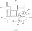
- Fig. 3G is a cross-sectional view of the housing body 202 shown in Fig. 2 taken along a section line D-D in Fig. 3D , showing the specific arrangement of a sixth flow port 366.
- the first group of flow ports further includes the sixth flow port 366.
- the sixth flow port 366 is arranged at the junction between the wall of the first cut cylindrical cavity 311 and the wall of the second cut cylindrical cavity 312.
- the sixth flow port 366 is arranged within the range of an included angle between the reverse direction of the third direction and the second direction, and the height of the sixth flow port is slightly lower than that of the second flow port 362 in the first direction.
- the height of the sixth flow port 366 is set to enable the sixth flow port 366 to cooperate with the second valve body 134. In other words, when the second valve body 134 rotates, the second valve body 134 can selectively connect or disconnect the sixth flow port 366.
- the pipe 370 is provided around the sixth flow port 366 and extends outward from the housing body 202.
- the orifice 375 of the pipe 370 is blocked by the cover 203, such that the fluid cannot flow into or out of the housing body 202 from the orifice 375.
- the housing body 202 further comprises a pipe 371 provided perpendicular to the pipe 370.
- the pipe 371 and the pipe 370 can fluidly be connected. In this way, the fluid flowing out of or into the housing body 202 through the sixth flow port 366 can flow through orifices 373, 374 of the pipe 371.
- a second group of flow ports are provided on the wall of the second cavity 114.
- the second group of flow ports include a seventh flow port 367 and an eighth flow port 368.
- the seventh flow port 367 is arranged within the range of an included angle between the second direction and the third direction, and is arranged to be higher than the fourth flow port 364 in the first direction.
- the eighth flow port 368 is arranged within the range of an included angle between the reverse direction of the third direction and the second direction, and the height of the eighth flow port is slightly lower than that of the seventh flow port 367 in the first direction.
- the heights of the seventh flow port 367 and the eighth flow port 368 are set to enable the seventh flow port 367 and the eighth flow port 368 to cooperate with the third valve body 136. In other words, when the third valve body 136 rotates, the third valve body 136 can selectively connect or disconnect the seventh flow port 367 and/or the eighth flow port 368.
- Each of the seventh flow port 367 and the eighth flow port 368 is provided with a pipe that surrounds the flow port and extends outward from the housing body 202, such that each flow port can be connected to other devices or pipes through the pipe.
- the second group of flow ports further include a pump outlet flow port 369.
- the pump outlet flow port 369 is provided on the vertical partition plate 324 for connecting with a pump outlet (not shown).
- the pump outlet flow port 369 is arranged within the range of an included angle between the reverse direction of the second direction and the reverse direction of the third direction, and the height of the pump outlet flow port 369 is set to enable the pump outlet flow port 369 to cooperate with the third valve body 136. In other words, when the third valve body 136 rotates, the third valve body 136 can selectively connect or disconnect the pump outlet flow port 369.
- the adjustable valve 100 in the present disclosure uses a pump (not shown) as a power source for fluid flow.
- the second transversal partition plate 323 at the top of the first cavity 112 is provided with a plurality of through holes 342 for connecting with an inlet of the pump.
- An opening 399 at the top of the second cavity 114 can be covered by the pump.
- the fluid in the first cavity 112 can flow out of the housing 101 through a plurality of holes 242 and enter the pump, and then the fluid flowing out through the pump outlet can enter the second cavity 114 through the pump outlet flow port 369.
- the actuator (not shown) is used as a power source for the rotation of the actuating shaft 118 in the present disclosure.
- the bottom of the first cavity 112 has a circular hole 303 for disposing the actuator.
- the actuator can be connected to the actuating shaft 118 through the hole 303 to drive the actuating shaft 118 to rotate.
- Fig. 4A is a perspective view of the actuating shaft 118 shown in Fig. 1B as viewed from top to bottom at an angle.
- Fig. 4B is a perspective view of the actuating shaft shown in Fig. 1B as viewed from bottom to top at another angle.
- the actuating shaft 118 comprises a shaft rod 401.
- An upper end 410 of the shaft rod 401 is designed to cooperate with the concave portion 394 in the housing body 202, such that the shaft rod 401 can be rotatably connected to the housing 101.
- a lower end 412 of the shaft rod 401 is designed to cooperate with an output end of the actuator, such that the actuator can drive the actuating shaft 118 to rotate during operation.
- the adjustable valve 100 comprises a first engageable and disengageable actuating structure 402, a second engageable and disengageable actuating structure 403, and a third engageable and disengageable actuating structure 404 that are provided on the shaft rod 401.
- the first engageable and disengageable actuating structure 402 is provided at an upper portion of the shaft rod 401.
- the first engageable and disengageable actuating structure 402 comprises a first transversal plate 422 and a plurality of first rods 424, 426, 428.
- the first transversal plate 422 is substantially sector-shaped, and is transversely provided at the upper portion of the shaft rod 401, such that a circumferential direction of the sector is identical to a circumferential direction of the shaft rod 401.
- the center of a circle of the sector on the axis of the shaft lever 401 such that when the actuating shaft 118 rotates about the first axis X, the plurality of first rods 424, 426, 428 on the first transversal plate 422 can also rotate about the first axis X.
- the plurality of first rods 424, 426, 428 are uniformly provided near an outer edge of the first transversal plate 422 along a circumferential direction of the first transversal plate 422, and extend downward from a bottom surface of the first transversal plate 422.
- the plurality of first rods 424, 426, 428 are provided to cooperate with a first engageable and disengageable actuated structure 555 on the first valve body 132, such that when the actuating shaft 118 rotates within a first angle range, the first engageable and disengageable actuating structure 402 (i.e., at least one of the plurality of first rods 424, 426, 428) on the actuating shaft 118 can drive the first valve body 132 to rotate together.
- the second engageable and disengageable actuating structure 403 comprises a second transversal arm 432 and a second rod 433.
- the second transversal arm 432 is substantially elongated, and extends perpendicularly from the shaft rod 401 in a radial direction of the shaft rod 401, such that when the shaft rod 401 rotates, a distal end 436 of the second transversal arm 432 can move in the circumferential direction.
- the second rod 433 is provided at the distal end 436 of the second transversal arm 432 and extends upward from an upper surface of the second transversal arm 432.
- the second rod 433 is provided to cooperate with a second engageable and disengageable actuated structure 755 on the second valve body 134, such that when the actuating shaft 118 rotates within a second angle range, the second engageable and disengageable actuating structure 403 (i.e., the second rod 433) on the actuating shaft 118 can drive the second valve body 134 to rotate together.
- the third engageable and disengageable actuating structure 404 comprises a third transversal arm 442 and a third rod 443.
- the third transversal arm 442 is substantially elongated, and extends perpendicularly from the upper portion of the shaft rod 401 in the radial direction of the shaft rod 401, such that when the shaft rod 401 rotates, a distal end 446 of the third transversal arm 442 can move in the circumferential direction.
- the third rod 443 is provided at the distal end 446 of the third transversal arm 442 and extends downward from a lower surface of the third transversal arm 442.
- the third rod 443 is provided to cooperate with a third engageable and disengageable actuated structure 955 on the third valve body 136 and a fourth engageable and disengageable actuated structure 1155 on the fourth valve body 138, such that when the actuating shaft 118 rotates within a third angle range, the third engageable and disengageable actuating structure 404 (i.e., the third rod 443) on the actuating shaft 118 can drive the third valve body 136 to rotate; and when the actuating shaft 118 rotates within a fourth angle range, the third engageable and disengageable actuating structure 404 (i.e., the third rod 443) on the actuating shaft 118 can drive the fourth valve body 138 to rotate.
- the third engageable and disengageable actuating structure 404 i.e., the third rod 443
- Fig. 5A is a perspective view of the first valve body 132 shown in Fig. 1B as viewed from top to bottom.
- Fig. 5B is a perspective view of the first valve body 132 shown in Fig. 1B as viewed from bottom to top.
- the first valve body 132 is substantially a sphere with upper and lower portions cut, and has the rotating shaft 162.
- a lower portion of the rotating shaft 162 is provided with a recess 552 to form the sleeve 155.
- the sleeve 155 is used to receive an upper end of the rotating shaft 164 of the second valve body 134, such that the first valve body 132 and the second valve body 134 can rotate about the same first axis X.
- An upper portion 502 of the first valve body 132 is designed to cooperate with the concave portion 393 of the second transversal partition plate 323, such that the upper portion 502 of the first valve body 132 can be received by the concave portion 393.
- the sphere of the first valve body 132 is provided with the first engageable and disengageable actuated structure 555.
- the first engageable and disengageable actuated structure 555 includes a plurality of first grooves 512, 513, 514, 515, 516, 517.
- the plurality of first grooves 512, 513, 514, 515, 516, 517 are provided on an upper surface of the sphere of the first valve body 132, and are arranged along a circumferential direction of the first valve body 132.
- the plurality of first grooves 512, 513, 514, 515, 516, 517 are formed by grooving from an edge of the sphere of the first valve body 132 to the inside of the sphere, and the central angle formed by the distribution of the plurality of first grooves 512, 513, 514, 515, 516, 517 on the sphere of the first valve body 132 is ⁇ .
- the first valve body 132 is provided with two openings 562, 564, and the two openings 562, 564 are configured such that when the first valve body 132 rotates, at least one of the two openings 562, 564 can be selectively aligned with the first flow port 361 and/or the second flow port 362 on the wall of the first cavity 112, to respectively connect and disconnect the first flow port 361 and the second flow port 362.
- Fig. 6 is a schematic view of a cooperation relationship between the first valve body 132 and the actuating shaft 118, exemplarily showing one of the states when the first engageable and disengageable actuating structure 402 engages with the first engageable and disengageable actuated structure 555.
- the actuating shaft 118 rotates within the first angle range, at least one of the plurality of first rods 424, 426, 428 on the actuating shaft 118 can engage with at least one of the plurality of first grooves 512, 513, 514, 515, 516, 517.
- the actuating shaft 118 can drive the first valve body 132 to rotate.
- first valve body 132 is sleeved on the second valve body 134, but due to the friction between the first valve body 132 and the second valve body 134, when the first valve body 132 rotates, the second valve body 134 does not rotate with the first valve body 132.
- Fig. 7A is a perspective view of the second valve body 134 shown in Fig. 1B as viewed from top to bottom.
- Fig. 7B is a perspective view of the second valve body 134 shown in Fig. 1B as viewed from bottom to top.
- the second valve body 134 comprises a second valve body main body 733 and the rotating shaft 164.
- the top of the rotating shaft 164 is stepped, and can be received by the sleeve 155 at the lower portion of the first valve body 132, such that the first valve body 132 and the second valve body 134 can rotate about the same first axis X.
- the second valve body main body 733 is substantially a spherical shell with upper and lower portions cut, and the second valve body main body 733 is disposed around the rotating shaft 164.
- a lower portion of the second valve body main body 733 is fixedly connected to the rotating shaft 164 via a plurality of connecting posts 704, 706, 708.
- the second valve body main body 733 is provided with an opening 762, and the opening 762 is configured such that when the second valve body 134 rotates, the opening 762 can be selectively aligned with the third flow port 363 and/or the sixth flow port 366 on the wall of the first cavity 112, to connect and disconnect the third flow port 363 and the sixth flow port 366.
- a second engageable and disengageable actuated structure 755 is provided at the lower portion of the rotating shaft 164.
- the second engageable and disengageable actuated structure 755 comprises a second valve body plate 712.
- One end of the second valve body plate 712 is connected to the lower portion of the rotating shaft 164, the other end of the second valve body plate 712 is provided with a second groove 722.
- the second groove 722 is arranged in a radial direction of the second valve body 134.
- Fig. 8 is a schematic view of a cooperation relationship between the second valve body 134 and the actuating shaft 118, exemplarily showing one of the states when the second engageable and disengageable actuating structure 403 engages with the second engageable and disengageable actuated structure 755.
- the second rod 433 on the actuating shaft 118 engages with the second groove 722.
- the actuating shaft 118 can drive the second valve body 134 to rotate within the second angle range.
- first valve body 132 is sleeved on the second valve body 134, but due to the friction between the first valve body 132 and the second valve body 134, when the second valve body 134 rotates, the first valve body 132 does not rotate with the rotation of the second valve body 134.
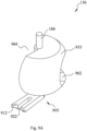
- Fig. 9A is a perspective view of the third valve body 136 shown in Fig. 1B as viewed from top to bottom at an angle.
- Fig. 9B is a perspective view of the third valve body 136 shown in Fig. 1B as viewed from bottom to top at another angle.
- the third valve body 136 comprises a third valve body main body 933 and the rotating shaft 166.
- the top of the rotating shaft 166 is received by a connecting portion provided on the pump.
- the lower portion of the rotating shaft 166 is provided with a recess 902 to form the sleeve 156.
- the sleeve 156 is used to receive an upper end of the rotating shaft 168 of the fourth valve body 138, such that the third valve body 136 and the fourth valve body 138 can rotate about the same second axis Y
- the third valve body main body 933 is substantially in the shape of a spherical shell, and is disposed around the rotating shaft 166.
- the lower portion of the third valve body main body 933 are fixedly connected to the rotating shaft 166 via a connecting plate 904.
- the third valve body main body 933 is provided with two openings 962, 964.
- the two openings 962, 964 are configured such that when the third valve body 136 rotates, at least one of the two openings 962, 964 can be selectively aligned with the pump outlet flow port 369, the seventh flow port 367 and/or the eighth flow port 368 on the wall of the second cavity 114, in order to connect and disconnect the pump outlet flow port 369, the seventh flow port 367 and the eighth flow port 368.
- a third engageable and disengageable actuated structure 955 is provided at the lower portion of the rotating shaft 166.
- the third engageable and disengageable actuated structure 955 comprises a third valve body plate 912.
- One end of the third valve body plate 912 is connected to the lower portion of the rotating shaft 166, the other end of the third valve body plate 912 is provided with a third groove 922.
- the third groove 922 is arranged in a radial direction of the third valve body 136.
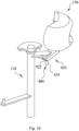
- Fig. 10 is a schematic view of a cooperation relationship between the third valve body 136 and the actuating shaft 118, exemplarily showing one of the states when the third engageable and disengageable actuating structure 404 engages with the third engageable and disengageable actuated structure 955.
- the third rod 443 on the actuating shaft 118 engages with the third groove 922 on the third valve body 136.
- the actuating shaft 118 can drive the third valve body 136 to rotate within the third angle range.
- the third valve body 136 is sleeved on the fourth valve body 138, but due to the friction between the third valve body 136 and the fourth valve body 138, when the third valve body 136 rotates, the fourth valve body 138 does not rotate with the rotation of the second valve body 134.
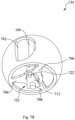
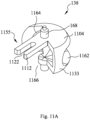
- Fig. 11A is a perspective view of the fourth valve body 138 shown in Fig. 1B as viewed from top to bottom at an angle.
- Fig. 11B is a perspective view of the fourth valve body 138 shown in Fig. 1B as viewed from bottom to top at another angle.
- the fourth valve body 138 comprises a fourth valve body main body 1133 and the rotating shaft 168.
- the top of the rotating shaft 166 is stepped, such that the top of the rotating shaft 166 can be received by the sleeve 156 at the lower portion of the third valve body 136, and the third valve body 136 and the fourth valve body 138 can rotate about the same second axis Y
- the fourth valve body main body 1133 is substantially in the shape of a spherical shell, and is provided around the rotating shaft 168. Connecting plates 1104, 1105 are respectively provided at an upper portion and a lower portion of the fourth valve body main body 1133 and are fixedly connected to the rotating shaft 168.
- the fourth valve body main body 1133 is provided with three openings 1162, 1164, 1166, and the three openings 1162, 1164, 1166 are configured such that when the fourth valve body 138 rotates, at least one of the three openings 1162, 1164, 1166 can be selectively aligned with the fourth flow port 364 on the wall of the first cavity 112, to connect and disconnect the fourth flow port 364.
- a fourth engageable and disengageable actuated structure 1155 is provided at an upper portion of the rotating shaft 168.
- the fourth engageable and disengageable actuated structure 1155 comprises a fourth valve body plate 1112.
- One end of the fourth valve body plate 1112 is connected to the upper portion of the rotating shaft 168, the other end of the fourth valve body plate 1112 is provided with a fourth groove 1122, and the fourth groove 1122 is arranged in a radial direction of the fourth valve body 138.
- Fig. 12 is a schematic view of a cooperation relationship between the fourth valve body 138 and the actuating shaft 118, exemplarily showing one of the states when the third engageable and disengageable actuating structure 404 engages with the fourth engageable and disengageable actuated structure 1155.
- the third rod 443 on the actuating shaft 118 engages with the fourth groove 1122.
- the actuating shaft 118 can drive the fourth valve body 138 to rotate within the fourth angle range.
- the third valve body 136 is sleeved on the fourth valve body 138, but due to the friction between the third valve body 136 and the fourth valve body 138, when the fourth valve body 138 rotates, the third valve body 136 does not rotate with the rotation of the fourth valve body 138.
- the third engageable and disengageable actuated structure 955 and the fourth engageable and disengageable actuated structure 1155 respectively cooperate with the third engageable and disengageable actuating structure 404 to form the third engaging and disengaging structure and the fourth engaging and disengaging structure.
- groove walls on two sides of the third groove 922 and groove walls at two ends of the fourth groove 1122 are different in length, the moment for engagement and disengagement of the third engaging and disengaging structure and the fourth engaging and disengaging structure is also different.
- the third engaging and disengaging structure can be engaged when the actuating shaft 118 rotates within the third angle range
- the fourth engaging and disengaging structure can be engaged when the actuating shaft 118 rotates within the fourth angle range.
- first engaging and disengaging structure, the second engaging and disengaging structure, the third engaging and disengaging structure, and the fourth engaging and disengaging structure in the present disclosure substantially use the way of grooves and rods to achieve engagement and disengagement, in order to clearly illustrate the specific cooperation relationship in the engaging and disengaging structure, the third engaging and disengaging structure is taken as an example in the present disclosure for detailed description below.
- Figs. 13A-13H are schematic views of the third engaging and disengaging structure during operation, showing how the third engaging and disengaging structure achieves engagement and disengagement.
- the third engaging and disengaging structure comprises the third engageable and disengageable actuating structure 404 and the third engageable and disengageable actuated structure 955.
- the third engageable and disengageable actuating structure 404 can engage with the third engageable and disengageable actuated structure 955, so as to drive the third engageable and disengageable actuated structure 955 to rotate together.
- Figs. 13A-13H schematically show the relative positional relationships among the shaft rod 401 of the actuating shaft 118, the third transversal arm 442, and the third rod 443.
- the shaft rod 401, the third transversal arm 442, and the third rod 443 rotate together about the third axis Z.
- 13A-13H also schematically show the relative positional relationships among the rotating shaft 166 of the third valve body 136, the third valve body plate 912, and the third groove 922.
- the rotating shaft 166, the third valve body plate 912, and the third groove 922 rotate together about the second axis Y
- Fig. 13A shows the relative positional relationship between the third engageable and disengageable actuating structure 404 and the third engageable and disengageable actuated structure 955 when the actuating shaft 118 has not yet rotated to an initial angle of the third angle range.
- the actuator drives the actuating shaft 118 to rotate counterclockwise (for example, as indicated by an arrow T in Fig. 13A ), such that the third engageable and disengageable actuating structure 404 also rotates counterclockwise.
- the third engageable and disengageable actuated structure 955 stays in a first position because it is not driven by the actuator.
- Fig. 13B shows the relative positional relationship between the third engageable and disengageable actuating structure 404 and the third engageable and disengageable actuated structure 955 when the actuating shaft 118 rotates to a first boundary angle of the third angle range. Specifically, when the actuating shaft 118 rotates counterclockwise to the initial angle of the third angle range, the third rod 443 of the actuating shaft 118 contacts a first side wall 1302 of the third groove 922, such that the third rod 443 is received in the third groove 922.
- Fig. 13C shows the relative positional relationship between the third engageable and disengageable actuating structure 404 and the third engageable and disengageable actuated structure 955 when the actuating shaft 118 rotates counterclockwise within the third angle range. Specifically, when the actuating shaft 118 continues to rotate counterclockwise, the third rod 443 pushes the first side wall 1302 of the third groove 922, such that the third valve body plate 912 rotates. Thereby, the third engageable and disengageable actuating structure 404 drives the third engageable and disengageable actuated structure 955 to rotate clockwise (for example, as indicated by an arrow U in Fig. 13C ).
- Fig. 13D shows that, when the actuating shaft 118 rotates to a second boundary angle of the third angle range, the third engageable and disengageable actuating structure 404 is disengaged from the third engageable and disengageable actuated structure 955.
- Fig. 13E shows that, when the actuating shaft 118 rotates beyond the third angle range, the third engageable and disengageable actuating structure 404 is disengaged from the third engageable and disengageable actuated structure 955.
- the third rod 443 is disengaged from the third groove 922, such that the actuating shaft 118 continues to rotate counterclockwise while the third engageable and disengageable actuated structure 955 retains in a second position. That is, at this time, the third engageable and disengageable actuating structure 404 cannot drive the third engageable and disengageable actuated structure 955 to rotate.
- Fig. 13F shows the relative positional relationship between the third engageable and disengageable actuating structure 404 and the third engageable and disengageable actuated structure 955 when the actuating shaft 118 rotates to the second boundary angle of the third angle range.
- the third engageable and disengageable actuating structure 404 also rotates clockwise.
- the third rod 443 of the actuating shaft 118 contacts a second side wall 1304 of the third groove 922, such that the third rod 443 is received in the third groove 922.
- Fig. 13G shows the relative positional relationship between the third engageable and disengageable actuating structure 404 and the third engageable and disengageable actuated structure 955 when the actuating shaft 118 rotates clockwise within the third angle range.
- the third rod 443 pushes the second side wall 1304 of the third groove 922, such that the third valve body plate 912 rotates.
- the third engageable and disengageable actuating structure 404 drives the third engageable and disengageable actuated structure 955 to rotate counterclockwise (for example, as indicated by an arrow V in Fig. 13G ).
- Fig. 13H shows that, when the actuating shaft 118 rotates to the first boundary angle of the third angle range, the third engageable and disengageable actuating structure 404 is disengaged from the third engageable and disengageable actuated structure 955.
- the third rod 443 is disengaged from the third groove 922, such that the actuating shaft 118 continues to rotate clockwise while the third engageable and disengageable actuated structure 955 retains in the first position. That is, at this time, the third engageable and disengageable actuating structure 404 cannot drive the third engageable and disengageable actuated structure 955 to rotate.
- the third angle range is the angle at which the third engageable and disengageable actuating structure 404 can rotate to engage with the third engageable and disengageable actuated structure 955 so as to drive the third engageable and disengageable actuated structure 955 to rotate.
- first engageable and disengageable actuating structure 402 the second engageable and disengageable actuating structure 403, and the third engageable and disengageable actuating structure 404 are provided along different angle directions of the shaft rod 401.
- the engageable and disengageable actuating structures on the shaft rod 401 can selectively engage with the engageable and disengageable actuated structures on the valve bodies, thereby driving different valve bodies to rotate.
- first valve body 132 can cooperate with a first flow port 361 and a second flow port 362, so that the openings on the first valve body 132 can selectively open at least one of the first flow port 361 and the second flow port 362; an opening on the second valve body 134 can cooperate with a third flow port 363 and a sixth flow port 366, so that the opening on the second valve body 134 can selectively open at least one of the third flow port 363 and the sixth flow port 366; the openings on the third valve body 136 can cooperate with a seventh flow port 367 and an eighth flow port 368, so that the openings on the third valve body
- the adjustable valve 100 can achieve multiple fluidly connection relationships as shown in Table 1. Table 1 No.
- serial numbers 1-10 on the left side of Table 1 indicate that the actuating shaft 118 rotates at different angles.
- the serial number 1 indicates that the actuating shaft 118 rotates at a first angle.
- the serial numbers 1-10 indicate the angles that the actuating shaft 118 rotates from an initial angle in the same direction.
- the actuating shaft 118 can rotate in both directions (i.e., rotating clockwise and counterclockwise).
- the symbol “O” in Table 1 indicates that the flow port is fully connected, that is, the flow port on the housing is aligned with the opening on the valve body, such that the fluid can flow through the entire area of the flow port on the housing.
- the symbol “R” in Table 1 indicates that the flow port is partially connected, that is, the flow port on the housing is partially aligned with the opening on the valve body, such that the fluid can only flow through the portion where the flow port is aligned with the opening of the valve body.
- the symbol “ ⁇ ” in Table 1 indicates that the flow port is disconnected, that is, the flow port is blocked by the valve body main body, such that the fluid cannot flow through the flow port on the housing. It should be noted that "connected” in the present disclosure includes a fully connected state and a partially connected state.
- a plurality of fluid passages can be formed in the valve 100 by controlling the opening and closing states of the flow ports on the housing, and the cooperation between the valve bodies.
- Each fluid passage is used to communicate two corresponding flow ports, so that the external pipes connected to the two corresponding flow ports can be communicated through the fluid passage.
- the plurality of fluid passages in the valve 100 can be connected or disconnected by controlling the rotation of the respective valve bodies.
- the fourth flow port 364 listed in Table 1 is used as a fluid inlet of the valve 100, and the remaining seven flow ports are used as fluid outlets of the valve 100, there are seven fluid passages in the valve 100, the seven fluid passages comprising a fluid passage 1, a fluid passage 2, a fluid passage 3, a fluid passage 5, a fluid passage 6, a fluid passage 7, and a fluid passage 8.
- the fluid passage 1 connects the fourth flow port 364 and the first flow port 361
- the fluid passage 2 connects the fourth flow port 364 and the second flow port 362
- the fluid passage 3 connects the fourth flow port 364 and the third flow port 363
- the fluid passage 5 connects the fourth flow port 364 and the fifth flow port 365
- the fluid passage 6 connects the fourth flow port 364 and the sixth flow port 366
- the fluid passage 7 connects the fourth flow port 364 and the seventh flow port 367
- the fluid passage 8 connects the fourth flow port 364 and the eighth flow port 368.
- valve body opening portion on the first valve body 132 is aligned with the first flow port 361, so that the first flow port 361 is opened; the valve body opening portion on the first valve body 132 is aligned with the second flow port 362, so that the second flow port 362 is opened; the valve body opening portion on the second valve body 134 is aligned with the third flow port 363, so that the third flow port 363 is opened; the valve body opening portion on the fourth valve body 138 is aligned with the fifth flow port 365, so that the fifth flow port 365 is opened; the valve body opening portion on the third valve body 136 is aligned with the seventh flow port 367, so that the seventh flow port 367 is opened; the valve body opening portion on the third valve body 136 is aligned with the eighth flow port 368, so that the eighth flow port 368 is opened; and the valve body opening portion on the second valve body 134 is not aligned with the sixth flow port 366, so that the sixth flow port 366 is closed or
- the fluid passage 1 that connects the fourth flow port 364 and the first flow port 361 is connected
- the fluid passage 2 that connects the fourth flow port 364 and the second flow port 362 is connected
- the fluid passage 3 that connects the fourth flow port 364 and the third flow port 363 is connected
- the fluid passage 5 that connects the fourth flow port 364 and the fifth flow port 365 is connected
- the fluid passage 7 that connects the fourth flow port 364 and the seventh flow port 367 is connected
- the fluid passage 8 that connects the fourth flow port 364 and the eighth flow port 368 is connected
- the fluid passage 6 that connects the fourth flow port 364 and the sixth flow port 366 is disconnected.
- valve body opening portion on the first valve body 132 is aligned with the first flow port 361, so that the first flow port 361 is opened; the valve body opening portion on the first valve body 132 is aligned with the second flow port 362, so that the second flow port 362 is opened; the valve body opening portion on the second valve body 134 is aligned with the third flow port 363, so that the third flow port 363 is opened; the valve body opening portion on the fourth valve body 138 is aligned with the fifth flow port 365, so that the fifth flow port 365 is opened; the valve body opening portion on the second valve body 134 is aligned with the sixth flow port 366, so that the sixth flow port 366 is opened; the valve body opening portion on the third valve body 136 is aligned with the seventh flow port 367, so that the seventh flow port 367 is opened; and the valve body opening portion on the third valve body 136 is aligned with the eighth flow port 368, so that the eighth flow port 368 is opened.
- the fluid passage 1 that connects the fourth flow port 364 and the first flow port 361 is connected
- the fluid passage 2 that connects the fourth flow port 364 and the second flow port 362 is connected
- the fluid passage 3 that connects the fourth flow port 364 and the third flow port 363 is connected
- the fluid passage 5 that connects the fourth flow port 364 and the fifth flow port 365 is connected
- the fluid passage 6 that connects the fourth flow port 364 and the sixth flow port 366 is connected
- the fluid passage 7 that connects the fourth flow port 364 and the seventh flow port 367 is connected
- the fluid passage 8 that connects the fourth flow port 364 and the eighth flow port 368 is connected.
- the valve 100 according to the embodiment is shown in Figs. 1A to 14 .
- a variety of fluid passages can be formed in the valve 100 by configuring a power device such as a pump, so that the valve 100 is used as a switching device of the cooling path to achieve the purpose of switching the cooling path.
- the adjustable valve 100 in the present disclosure can switch different passages for the fluid and can also control the flow of each passage by the arrangement of the openings on the valve bodies and the flow ports.
- a control assembly in the system can switch different passages for the fluid by controlling less elements, and the stability of system control can be enhanced while integrated control is achieved.
- the adjustable valve 100 further comprises a first group of sealing elements and a second group of sealing elements.
- Each of the first group of sealing elements is disposed between the first valve body 132, the second valve body 134 or the fourth valve body 138 and each of the first group of flow ports.
- Each of the first group of sealing elements is configured to abut against the cavity wall where each of the first group of flow ports is located, such that when the valve body rotates, the first group of sealing elements can abut against the cavity wall and does not rotate with the rotation of the valve body.
- the second group of sealing elements include two sealing elements, one of the two sealing elements is disposed between the seventh flow port 367 and the third valve body 136, and the other one of the two sealing elements is disposed between the eighth flow port 368 and the third valve body 136. Since the pump outlet flow port 369 in the second group of flow ports is connected to the outlet of the pump, no sealing element is provided there.
- the actuator that drives the valve body to rotate requires a larger driving force to drive the valve body to rotate, so as to overcome the friction between the valve body and the sealing element.
- the actuating shaft of the valve needs to overcome the friction generated by the relative movement of all the sealing elements and the valve bodies provided in the housing, such that the required power of the actuator is relatively large.
- the actuating shaft 118 of the adjustable valve 100 in the present disclosure selectively makes actuating structure engage with the actuated structure at one time, and the actuating structure drives the actuated structure rotate, so that the actuating shaft 118 drives at least one of the first valve body 132, the second valve body 134, the third valve body 136, and the fourth valve body 138 to rotate.
- the adjustable valve 100 in the present disclosure also has the following advantages: when the fluid passage required in the adjustable valve 100 can be realized by the rotation of the valve body on one side of the actuating shaft 118, since the valve body on the other side does not rotate, there is no friction between the non-rotating valve body and the sealing element, the driving force provided by the actuator is reduced.
- the actuator is only required to provide the power to overcome the friction produced by the valve body which needs to be rotated by the actuating shaft 118.
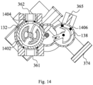
- the states of the valve bodies in the adjustable valve 100 at the serial numbers 8-10 in Table 1 will be described below as an example.
- Fig. 14 is a schematic view of the adjustable valve 100 shown in Fig. 1A cut to the first flow port 361 and the second flow port 362 in the horizontal direction.
- Fig. 14 shows a first sealing element 1402 disposed between the first valve body 132 and the first flow port 361, a second sealing element 1404 disposed between the first valve body 132 and the second flow port 362, and a third sealing element 1406 disposed between the fourth valve body 138 and the fifth flow port 365.
- the valve provided by the present disclosure is particularly suitable for disclosures that provide more fluid passages, because the actuating shaft of the valve of the present disclosure only needs to overcome the frictional force generated by the sealing element between the actuated at least one group of valve bodies and the housing, but not to overcome the frictional force generated by all the sealing elements between the valve bodies and the housing. Therefore, the output power of the actuator 190 does not need to increase with the increase of fluid passages in the valve.
Description
- The present disclosure relates to a valve, and more specifically to an adjustable valve being able to adjust flow and control the connection and disconnection of passage.
- An adjustable valve is applied in a vehicle. The adjustable valve controls a flow path of a cooling liquid by connecting different thermal control passages inside the vehicle, in order to adjust the temperature of various components inside the vehicle. The adjustable valve generally comprises a housing and a valve body disposed inside the housing. The housing is provided with housing flow ports. Each housing flow port is connected to a temperature adjustable system inside the vehicle via a pipeline. The valve body is provided with an opening. The valve body can rotate under an actuator, such that different opening of the valve body is aligned with a housing flow port to fluidly connect different flow ports of the housing, and then to fluidly connect different temperature adjustable passages in the temperature adjustable system.
- For example,
US 10094268 - As more and more components, which need to be adjustable, is provided inside the vehicle, the number of flow ports on the housing is increasing. An adjustable valve is needed to provide more fluid passages, thereby achieving different flow paths to form different thermal control passages.
- Exemplary embodiments of the present disclosure can address at least some of the above problems.
- The present disclosure provides an adjustable valve, comprising a housing, a first valve body, a second valve body, a third valve body, a fourth valve body, and an actuating shaft. The housing has a first cavity and a second cavity. The first valve body is disposed in the first cavity. The second valve body is disposed in the first cavity, and the first valve body and the second valve body can rotate about a first axis X. The third valve body is disposed in the second cavity. The fourth valve body is disposed in the first cavity, and the third valve body and the fourth valve body can rotate about a second axis Y The actuating shaft is rotatably disposed in the first cavity, and the actuating shaft can selectively drive one or more of the first valve body, the second valve body, the third valve body, and the fourth valve body to rotate.
- According to the adjustable valve, the adjustable valve further comprises a first engageable and disengageable actuating structure, a second engageable and disengageable actuating structure, and a third engageable and disengageable actuating structure provided on the actuating shaft.
- During the rotation of the actuating shaft, the first engageable and disengageable actuating structure, the second engageable and disengageable actuating structure, and the third engageable and disengageable actuating structure can rotate together.
- According to the adjustable valve, the adjustable valve further comprises a first engageable and disengageable actuated structure, a second engageable and disengageable actuated structure, a third engageable and disengageable actuated structure and a fourth engageable and disengageable actuated structure. The first engageable and disengageable actuated structure is provided on the first valve body. The first engageable and disengageable actuated structure can be cooperated with the first engageable and disengageable actuating structure to form a first engaging and disengaging structure, such that the first valve body can engage or disengage with the actuating shaft. The second engageable and disengageable actuated structure is provided on the second valve body, wherein the second engageable and disengageable actuated structure can be cooperated with the second engageable and disengageable actuating structure to form a second engaging and disengaging structure, such that the second valve body can engage or disengage with the actuating shaft. The third engageable and disengageable actuated structure is provided on the third valve body, wherein the third engageable and disengageable actuated structure can be cooperated with the third engageable and disengageable actuating structure to form a third engaging and disengaging structure, such that the third valve body can engage or disengage with the actuating shaft. The fourth engageable and disengageable actuated structure is provided on the fourth valve body, wherein the fourth engageable and disengageable actuated structure can be cooperated with the third engageable and disengageable actuating structure to form a fourth engaging and disengaging structure, such that the fourth valve body can engage or disengage with the actuating shaft.
- According to the adjustable valve, the first engageable and disengageable actuating structure comprises a plurality of first rods, and the first engageable and disengageable actuated structure comprises a plurality of first grooves. The second engageable and disengageable actuating structure comprises a second rod, and the second engageable and disengageable actuated structure comprises a second groove. The third engageable and disengageable actuating structure comprises a third rod, the third engageable and disengageable actuated structure comprises a third groove, and the fourth engageable and disengageable actuated structure comprises a fourth groove .
- According to the adjustable valve, when the actuating shaft rotates within a first angle range, at least one of the plurality of first rods can engage with one of the plurality of first grooves, such that the actuating shaft can drive the first valve body to rotate. When the actuating shaft rotates within a second angle range, the second rod can engage with the second groove, such that the actuating shaft can drive the second valve body to rotate. When the actuating shaft rotates within a third angle range, the third rod can engage with the third groove, such that the actuating shaft can drive the third valve body to rotate. When the actuating shaft rotates within a fourth angle range, the third rod can engage with the fourth groove, such that the actuating shaft can drive the fourth valve body to rotate.
- According to the adjustable valve, the first cavity has a first group of flow ports on cavity wall thereof, and the second cavity has a second group of flow ports on cavity wall thereof. The first valve body has a first group of openings thereon, the second valve body has a second group of opening thereon, the third valve body has a third group of opening thereon, and the fourth valve body has a fourth group of opening thereon.
- According to the adjustable valve, the top portion of the housing has step portion, the second cavity is provided above the step portion and the first cavity is provided below the step portion, such that the second cavity is at least partially located above the first cavity .
- According to the adjustable valve, the second group of flow ports include a pump outlet flow port. The upper portion of the first cavity is used for connecting to pump inlet and the pump outlet flow port is used for connecting to the pump outlet, such that the first cavity can fluidly connect the second cavity via the pump.
- According to the adjustable valve, the adjustable valve further comprises a first group of sealing elements and a second group of sealing elements.
- Each sealing element of the first group of sealing elements is respectively disposed between the first valve body and corresponding one of the first group of flow ports, between the second valve body and corresponding one of the first group of flow ports, between the fourth valve body and corresponding one of the first group of flow ports.
- The second group of flow ports include seventh flow port and eighth flow port, one of the second group of sealing elements is disposed between the third valve body and the seventh flow port, and another of the second group of sealing elements is disposed between the third valve body and the eighth flow port.
- According to the adjustable valve, an actuator is disposed under the housing, and the actuating shaft is actuated by the actuator to rotate.
- The adjustable valve of the present disclosure can realize the connection and disconnection of different fluid passages, and can control the flow of each passage, which is beneficial to the integrated design of the system.
- The features and advantages of the present disclosure may be better understood by reading the following detailed description with reference to the accompanying drawings. In all the accompanying drawings, the same reference numerals represent the same parts, wherein:
-
Fig. 1A is a perspective view of an adjustable valve according to an embodiment of the present disclosure; -
Fig. 1B is an exploded view of the adjustable valve shown inFig. 1A ; -
Fig. 1C is a cross-sectional view of the adjustable valve shown inFig. 1A taken along a section line A-A inFig. 1A ; -
Fig. 2 is an exploded view of a housing shown inFig. 1A ; -
Fig. 3A is a perspective view of a housing body shown inFig. 2 as viewed from top to bottom; -
Fig. 3B is a perspective view of the housing body shown inFig. 2 as viewed from bottom to top; -
Fig. 3C is a top view of the housing body shown inFig. 2 ; -
Fig. 3D is a bottom view of the housing body shown inFig. 2 ; -
Fig. 3E is a cross-sectional view of the housing body shown inFig. 2 taken along a section line B-B inFig. 3A ; -
Fig. 3F is a cross-sectional view of the housing body shown inFig. 2 taken along a section line C-C inFig. 3A ; -
Fig. 3G is a cross-sectional view of the housing body shown inFig. 2 taken along a section line D-D inFig. 3D ; -
Fig. 4A is a perspective view of an actuating shaft shown inFig. 1B as viewed from top to bottom; -
Fig. 4B is a perspective view of the actuating shaft shown inFig. 1B as viewed from bottom to top; -
Fig. 5A is a perspective view of a first valve body shown inFig. 1B as viewed from top to bottom; -
Fig. 5B is a perspective view of the first valve body shown inFig. 1B as viewed from bottom to top; -
Fig. 6 is a schematic view of a cooperation relationship between the first valve body and the actuating shaft; -
Fig. 7A is a perspective view of a second valve body shown inFig. 1B as viewed from top to bottom; -
Fig. 7B is a perspective view of the second valve body shown inFig. 1B as viewed from bottom to top; -
Fig. 8 is a schematic view of a cooperation relationship between the second valve body and the actuating shaft; -
Fig. 9A is a perspective view of a third valve body shown inFig. 1B as viewed from top to bottom; -
Fig. 9B is a perspective view of the third valve body shown inFig. 1B as viewed from bottom to top; -
Fig. 10 is a schematic view of a cooperation relationship between the third valve body and the actuating shaft; -
Fig. 11A is a perspective view of a fourth valve body shown inFig. 1B as viewed from top to bottom at an angle; -
Fig. 11B is a perspective view of the fourth valve body shown inFig. 1B as viewed from bottom to top at another angle; -
Fig. 12 is a schematic view of a cooperation relationship between the fourth valve body and the actuating shaft; -
Figs. 13A-13H are schematic views of a third engaging and disengaging structure during operation; and -
Fig. 14 is a schematic view of the adjustable valve shown inFig. 1A cut to a first flow port and a second flow port in a horizontal direction. - Particular embodiments of the present disclosure are described below with reference to the accompanying drawings which constitute part of this description. It should be understood that, in the following accompanying drawings, the same reference numerals are used for the same components, and similar reference numerals are used for similar components.
- Particular embodiments of the present disclosure are described below with reference to the accompanying drawings which constitute part of this description. It is to be understood that although the terms indicating orientations, such as "front", "rear", "upper", "lower", "left", "right", "inner", "outer", "top" and "bottom", are used in the present disclosure to describe structural parts and elements in various examples of the present disclosure, these terms are used herein only for ease of illustration and are determined based on the exemplary orientations as shown in the accompanying drawings. Since the embodiments disclosed in the present disclosure can be arranged in different directions, these terms indicating directions are only illustrative and should not be considered as limitations.
- The ordinal numbers such as "first" and "second" used in the disclosure are only used for distinguishing and identifying, and do not have any other meaning. If nothing is specified, they do not represent a specific order or have a specific relevance. For example, the term of "first part" itself does not imply the existence of "second part", nor does the term of "second part" itself imply the existence of "first part".
-
Fig. 1A is a perspective view of anadjustable valve 100 according to an embodiment of the present disclosure.Fig. 1B is an exploded view of theadjustable valve 100 shown inFig. 1A .Fig. 1C is a vertical downward cross-sectional view of theadjustable valve 100 shown inFig. 1A taken along a section line A-A inFig. 1A . In order to clearly show main components in theadjustable valve 100, sealing elements provided at respective flow ports are not shown inFigs. 1A-1C . As shown inFigs. 1A-1C , theadjustable valve 100 comprises ahousing 101, afirst valve body 132, asecond valve body 134, athird valve body 136, and afourth valve body 138. Thehousing 101 has afirst cavity 112 and asecond cavity 114. Thefirst valve body 132, thesecond valve body 134, and thefourth valve body 138 are disposed in thefirst cavity 112, and thethird valve body 136 is disposed in thesecond cavity 114. Asleeve 155 is provided at the bottom of arotating shaft 162 of thefirst valve body 132. Thesleeve 155 is sleeved at the top of arotating shaft 164 of thesecond valve body 134, such that thefirst valve body 132 and thesecond valve body 134 can rotate about the same first axis X. A lower portion of arotating shaft 166 of thethird valve body 136 passes through a firsttransversal partition plate 120 of thefirst cavity 112 and thesecond cavity 114 and then extends into thefirst cavity 112. Asleeve 156 is provided at the bottom of thethird valve body 136. Thesleeve 156 is sleeved at the top of arotating shaft 168 of thefourth valve body 138, such that thethird valve body 136 and thefourth valve body 138 can rotate about the same second axis Y - The
adjustable valve 100 further comprises anactuating shaft 118. Theactuating shaft 118 is disposed in thefirst cavity 112 and can rotate about a third axis Z. Thefirst valve body 132 and thesecond valve body 134 are disposed on a left side of theactuating shaft 118, and thethird valve body 136 and thefourth valve body 138 are disposed on a right side of theactuating shaft 118. Theadjustable valve 100 further comprises a first engaging and disengaging structure, a second engaging and disengaging structure, a third engaging and disengaging structure, and a fourth engaging and disengaging structure. When theactuating shaft 118 rotates, thefirst valve body 132, thesecond valve body 134, thethird valve body 136, and thefourth valve body 138 can respectively and selectively rotate together with theactuating shaft 118 via the first engaging and disengaging structure, the second engaging and disengaging structure, the third engaging and disengaging structure, and the fourth engaging and disengaging structure. -
Fig. 2 is an exploded view of thehousing 101 shown inFig. 1A . As shown inFig. 2 , thehousing 101 comprises ahousing body 202 and acover 203. The size of thecover 203 can cooperate with the size of anorifice 375 of apipe 370 on thehousing body 202. Thecover 203 can be mounted on theorifice 375 and blocks theorifice 375, so that a fluid in thehousing 101 cannot flow into or out of thehousing 101 through theorifice 375. -
Fig. 3A is a perspective view of thehousing body 202 shown inFig. 2 as viewed from top to bottom in front of thehousing 101.Fig. 3B is a perspective view of thehousing body 202 shown inFig. 2 as viewed from bottom to top in back of thehousing 101.Figs. 3C and3D are respectively a top view and a bottom view of thehousing body 202 shown inFig. 2 .Fig. 3E is a vertical downward cross-sectional view of thehousing body 202 shown inFig. 2 taken along a section line B-B inFig. 3A , showing more structural details inside thehousing body 202. In order to better describe the structure of thehousing body 202, in the present disclosure, an extension direction of each of the first axis X, the second axis Y, and the third axis Z is taken as a first direction, the direction of a horizontal connecting line between the first axis X and the third axis Z is taken as a second direction, and the direction perpendicular to the first direction and the second direction is taken as a third direction. - As shown in
Figs. 3A-3E , thehousing body 202 has a top plate. The top plate comprises a firsttransversal partition plate 120, a secondtransversal partition plate 323, and avertical partition plate 324. The firsttransversal partition plate 120 and the secondtransversal partition plate 323 are provided to have a height difference in the first direction to form astep portion 310. Thefirst cavity 112 is provided below the firsttransversal partition plate 120 and the secondtransversal partition plate 323, and thesecond cavity 114 is provided above the firsttransversal partition plate 120, so that the top of thesecond cavity 114 is partially higher than the top of thefirst cavity 112 in the first direction. - A
perforation 391 is provided in the firsttransversal partition plate 120. The lower portion of thethird valve body 136 can pass through theperforation 391, so that the lower portion of thethird valve body 136 extends into thefirst cavity 112, and thethird valve body 136 can rotate about the second axis Y - A
first bottom plate 395 of thefirst cavity 112 has aconcave portion 396 for receiving a lower portion of thefourth valve body 138. An upper portion of thefourth valve body 138 is connected to the lower portion of thethird valve body 136, and the lower portion of thefourth valve body 138 is received in theconcave portion 396 of thefirst bottom plate 395, so thefourth valve body 138 can be disposed in thefirst cavity 112 and can rotate about the second axis Y - The second
transversal partition plate 323 has aconcave portion 393 for receiving an upper portion of thefirst valve body 132. Asecond bottom plate 397 of thefirst cavity 112 has a concave portion 398 for receiving a lower portion of thesecond valve body 134. Because a lower portion of thefirst valve body 132 is sleeved with an upper portion of thesecond valve body 134, thefirst valve body 132 and thesecond valve body 134 can be disposed together in thefirst cavity 112 and can rotate about the first axis X. - The second
transversal partition plate 323 also has aconcave portion 394 for receiving an upper portion of theactuating shaft 118, such that when an actuator (not shown) drives theactuating shaft 118 to rotate, theactuating shaft 118 can rotate about the third axis Z. -
Fig. 3F is a cross-sectional view of thehousing body 202 shown inFig. 2 taken along a parallel direction of a section line C-C inFig. 3A , showing the shape of thefirst cavity 112 more clearly. As shown inFig. 3F , thefirst cavity 112 is substantially in the shape of three intersecting cylinders, thereby forming a first cutcylindrical cavity 311, a second cutcylindrical cavity 312, and a third cutcylindrical cavity 313. Thefirst valve body 132 and thesecond valve body 134 are disposed in the first cutcylindrical cavity 311. Theactuating shaft 118 is disposed in the second cutcylindrical cavity 312. Thefourth valve body 138 is disposed in the third cutcylindrical cavity 313. The central axis M of the first cutcylindrical cavity 311 coincides with the first axis X. The central axis N of the second cutcylindrical cavity 312 coincides with the third axis Z. The central axis O of the third cutcylindrical cavity 313 coincides with the second axis Y - It can be seen with reference to
Figs. 3A-3E that the wall of thefirst cavity 112 is provided with a first group of flow ports including afirst flow port 361 arranged in the third direction and asecond flow port 362 arranged reversely in the third direction. Thefirst flow port 361 and thesecond flow port 362 are arranged at the same height in the first direction, and the height of thefirst flow port 361 and thesecond flow port 362 is set to enable thefirst flow port 361 and thesecond flow port 362 to cooperate with thefirst valve body 132. In other words, when thefirst valve body 132 rotates, thefirst valve body 132 can selectively connect or disconnect thefirst flow port 361 and/or thesecond flow port 362. - The first group of flow ports further includes a
third flow port 363. Thethird flow port 363 is arranged within the range of an included angle between the reverse direction of the second direction and the third direction, and the height of the third flow port is lower than that of thefirst flow port 361 and thesecond flow port 362 in the first direction. The height of thethird flow port 363 is set to enable thethird flow port 363 to cooperate with thesecond valve body 134. In other words, when thesecond valve body 134 rotates, thesecond valve body 134 can selectively connect or disconnect thethird flow port 363. - The first group of flow ports further include a
fourth flow port 364. Thefourth flow port 364 is arranged within the range of an included angle between the reverse direction of the second direction and the reverse direction of the third direction, and is slightly lower than thethird flow port 363 in the first direction. The height of thefourth flow port 364 is lower than that of thesecond valve body 134. In other words, regardless of the angle to which thesecond valve body 134 rotates, thefourth flow port 364 remains fluidly connecting thefirst cavity 112. - Each of the
first flow port 361, thesecond flow port 362, thethird flow port 363, and thefourth flow port 364 is provided on the wall (i.e., the housing 101) of the first cutcylindrical cavity 311 around the central axis M of the first cutcylindrical cavity 311. - The first group of flow ports further include a
fifth flow port 365, which is arranged within the range of an included angle between the reverse direction of the third direction and the second direction, and the height of the fifth flow port is slightly lower than that of thesecond flow port 362 in the first direction. The height of thefifth flow port 365 is set to enable thefifth flow port 365 to cooperate with thefourth valve body 138. In other words, when thefourth valve body 138 rotates, thefourth valve body 138 can selectively connect or disconnect thefifth flow port 365. In addition, thefifth flow port 365 is provided on the wall of the third cutcylindrical cavity 313 around the central axis O of the third cutcylindrical cavity 313. - Each of the
first flow port 361, thesecond flow port 362, thethird flow port 363, thefourth flow port 364, and thefifth flow port 365 is provided with a pipe that surrounds the flow port and extends outward from thehousing body 202, such that each flow port can be connected to other devices or pipes through the pipe. -
Fig. 3G is a cross-sectional view of thehousing body 202 shown inFig. 2 taken along a section line D-D inFig. 3D , showing the specific arrangement of asixth flow port 366. As shown inFig. 3G , the first group of flow ports further includes thesixth flow port 366. Thesixth flow port 366 is arranged at the junction between the wall of the first cutcylindrical cavity 311 and the wall of the second cutcylindrical cavity 312. Thesixth flow port 366 is arranged within the range of an included angle between the reverse direction of the third direction and the second direction, and the height of the sixth flow port is slightly lower than that of thesecond flow port 362 in the first direction. The height of thesixth flow port 366 is set to enable thesixth flow port 366 to cooperate with thesecond valve body 134. In other words, when thesecond valve body 134 rotates, thesecond valve body 134 can selectively connect or disconnect thesixth flow port 366. - With reference to
Fig. 2 , thepipe 370 is provided around thesixth flow port 366 and extends outward from thehousing body 202. Theorifice 375 of thepipe 370 is blocked by thecover 203, such that the fluid cannot flow into or out of thehousing body 202 from theorifice 375. Thehousing body 202 further comprises apipe 371 provided perpendicular to thepipe 370. Thepipe 371 and thepipe 370 can fluidly be connected. In this way, the fluid flowing out of or into thehousing body 202 through thesixth flow port 366 can flow throughorifices pipe 371. - With continued reference to
Figs. 3A-3E , a second group of flow ports are provided on the wall of thesecond cavity 114. The second group of flow ports include aseventh flow port 367 and aneighth flow port 368. Theseventh flow port 367 is arranged within the range of an included angle between the second direction and the third direction, and is arranged to be higher than thefourth flow port 364 in the first direction. Theeighth flow port 368 is arranged within the range of an included angle between the reverse direction of the third direction and the second direction, and the height of the eighth flow port is slightly lower than that of theseventh flow port 367 in the first direction. The heights of theseventh flow port 367 and theeighth flow port 368 are set to enable theseventh flow port 367 and theeighth flow port 368 to cooperate with thethird valve body 136. In other words, when thethird valve body 136 rotates, thethird valve body 136 can selectively connect or disconnect theseventh flow port 367 and/or theeighth flow port 368. - Each of the
seventh flow port 367 and theeighth flow port 368 is provided with a pipe that surrounds the flow port and extends outward from thehousing body 202, such that each flow port can be connected to other devices or pipes through the pipe. - The second group of flow ports further include a pump
outlet flow port 369. The pumpoutlet flow port 369 is provided on thevertical partition plate 324 for connecting with a pump outlet (not shown). Specifically, the pumpoutlet flow port 369 is arranged within the range of an included angle between the reverse direction of the second direction and the reverse direction of the third direction, and the height of the pumpoutlet flow port 369 is set to enable the pumpoutlet flow port 369 to cooperate with thethird valve body 136. In other words, when thethird valve body 136 rotates, thethird valve body 136 can selectively connect or disconnect the pumpoutlet flow port 369. - As an example, the
adjustable valve 100 in the present disclosure uses a pump (not shown) as a power source for fluid flow. As shown inFig. 3A , the secondtransversal partition plate 323 at the top of thefirst cavity 112 is provided with a plurality of throughholes 342 for connecting with an inlet of the pump. Anopening 399 at the top of thesecond cavity 114 can be covered by the pump. In this way, the fluid in thefirst cavity 112 can flow out of thehousing 101 through a plurality of holes 242 and enter the pump, and then the fluid flowing out through the pump outlet can enter thesecond cavity 114 through the pumpoutlet flow port 369. - As an example, the actuator (not shown) is used as a power source for the rotation of the
actuating shaft 118 in the present disclosure. As shown inFig. 3B , the bottom of thefirst cavity 112 has acircular hole 303 for disposing the actuator. The actuator can be connected to theactuating shaft 118 through thehole 303 to drive the actuatingshaft 118 to rotate. -
Fig. 4A is a perspective view of theactuating shaft 118 shown inFig. 1B as viewed from top to bottom at an angle.Fig. 4B is a perspective view of the actuating shaft shown inFig. 1B as viewed from bottom to top at another angle. As shown inFigs. 4A and4B , theactuating shaft 118 comprises ashaft rod 401. Anupper end 410 of theshaft rod 401 is designed to cooperate with theconcave portion 394 in thehousing body 202, such that theshaft rod 401 can be rotatably connected to thehousing 101. Alower end 412 of theshaft rod 401 is designed to cooperate with an output end of the actuator, such that the actuator can drive the actuatingshaft 118 to rotate during operation. - The
adjustable valve 100 comprises a first engageable anddisengageable actuating structure 402, a second engageable anddisengageable actuating structure 403, and a third engageable anddisengageable actuating structure 404 that are provided on theshaft rod 401. Specifically, the first engageable anddisengageable actuating structure 402 is provided at an upper portion of theshaft rod 401. The first engageable anddisengageable actuating structure 402 comprises a firsttransversal plate 422 and a plurality offirst rods transversal plate 422 is substantially sector-shaped, and is transversely provided at the upper portion of theshaft rod 401, such that a circumferential direction of the sector is identical to a circumferential direction of theshaft rod 401. The center of a circle of the sector on the axis of theshaft lever 401, such that when theactuating shaft 118 rotates about the first axis X, the plurality offirst rods transversal plate 422 can also rotate about the first axis X. The plurality offirst rods transversal plate 422 along a circumferential direction of the firsttransversal plate 422, and extend downward from a bottom surface of the firsttransversal plate 422. The plurality offirst rods structure 555 on thefirst valve body 132, such that when theactuating shaft 118 rotates within a first angle range, the first engageable and disengageable actuating structure 402 (i.e., at least one of the plurality offirst rods actuating shaft 118 can drive thefirst valve body 132 to rotate together. - The second engageable and
disengageable actuating structure 403 comprises a secondtransversal arm 432 and asecond rod 433. The secondtransversal arm 432 is substantially elongated, and extends perpendicularly from theshaft rod 401 in a radial direction of theshaft rod 401, such that when theshaft rod 401 rotates, adistal end 436 of the secondtransversal arm 432 can move in the circumferential direction. Thesecond rod 433 is provided at thedistal end 436 of the secondtransversal arm 432 and extends upward from an upper surface of the secondtransversal arm 432. Thesecond rod 433 is provided to cooperate with a second engageable and disengageable actuatedstructure 755 on thesecond valve body 134, such that when theactuating shaft 118 rotates within a second angle range, the second engageable and disengageable actuating structure 403 (i.e., the second rod 433) on theactuating shaft 118 can drive thesecond valve body 134 to rotate together. - The third engageable and
disengageable actuating structure 404 comprises a thirdtransversal arm 442 and athird rod 443. The thirdtransversal arm 442 is substantially elongated, and extends perpendicularly from the upper portion of theshaft rod 401 in the radial direction of theshaft rod 401, such that when theshaft rod 401 rotates, adistal end 446 of the thirdtransversal arm 442 can move in the circumferential direction. Thethird rod 443 is provided at thedistal end 446 of the thirdtransversal arm 442 and extends downward from a lower surface of the thirdtransversal arm 442. Thethird rod 443 is provided to cooperate with a third engageable and disengageable actuatedstructure 955 on thethird valve body 136 and a fourth engageable and disengageable actuatedstructure 1155 on thefourth valve body 138, such that when theactuating shaft 118 rotates within a third angle range, the third engageable and disengageable actuating structure 404 (i.e., the third rod 443) on theactuating shaft 118 can drive thethird valve body 136 to rotate; and when theactuating shaft 118 rotates within a fourth angle range, the third engageable and disengageable actuating structure 404 (i.e., the third rod 443) on theactuating shaft 118 can drive thefourth valve body 138 to rotate. -
Fig. 5A is a perspective view of thefirst valve body 132 shown inFig. 1B as viewed from top to bottom.Fig. 5B is a perspective view of thefirst valve body 132 shown inFig. 1B as viewed from bottom to top. As shown inFigs. 5A and5B , thefirst valve body 132 is substantially a sphere with upper and lower portions cut, and has therotating shaft 162. A lower portion of therotating shaft 162 is provided with arecess 552 to form thesleeve 155. Thesleeve 155 is used to receive an upper end of therotating shaft 164 of thesecond valve body 134, such that thefirst valve body 132 and thesecond valve body 134 can rotate about the same first axis X. Anupper portion 502 of thefirst valve body 132 is designed to cooperate with theconcave portion 393 of the secondtransversal partition plate 323, such that theupper portion 502 of thefirst valve body 132 can be received by theconcave portion 393. - The sphere of the
first valve body 132 is provided with the first engageable and disengageable actuatedstructure 555. The first engageable and disengageable actuatedstructure 555 includes a plurality offirst grooves first grooves first valve body 132, and are arranged along a circumferential direction of thefirst valve body 132. Specifically, the plurality offirst grooves first valve body 132 to the inside of the sphere, and the central angle formed by the distribution of the plurality offirst grooves first valve body 132 is β. - The
first valve body 132 is provided with twoopenings openings first valve body 132 rotates, at least one of the twoopenings first flow port 361 and/or thesecond flow port 362 on the wall of thefirst cavity 112, to respectively connect and disconnect thefirst flow port 361 and thesecond flow port 362. -
Fig. 6 is a schematic view of a cooperation relationship between thefirst valve body 132 and theactuating shaft 118, exemplarily showing one of the states when the first engageable anddisengageable actuating structure 402 engages with the first engageable and disengageable actuatedstructure 555. As shown inFig. 6 , when theactuating shaft 118 rotates within the first angle range, at least one of the plurality offirst rods actuating shaft 118 can engage with at least one of the plurality offirst grooves actuating shaft 118 can drive thefirst valve body 132 to rotate. - It should be noted that the
first valve body 132 is sleeved on thesecond valve body 134, but due to the friction between thefirst valve body 132 and thesecond valve body 134, when thefirst valve body 132 rotates, thesecond valve body 134 does not rotate with thefirst valve body 132. -
Fig. 7A is a perspective view of thesecond valve body 134 shown inFig. 1B as viewed from top to bottom.Fig. 7B is a perspective view of thesecond valve body 134 shown inFig. 1B as viewed from bottom to top. As shown inFigs. 7A and7B , thesecond valve body 134 comprises a second valve bodymain body 733 and therotating shaft 164. The top of therotating shaft 164 is stepped, and can be received by thesleeve 155 at the lower portion of thefirst valve body 132, such that thefirst valve body 132 and thesecond valve body 134 can rotate about the same first axis X. - The second valve body
main body 733 is substantially a spherical shell with upper and lower portions cut, and the second valve bodymain body 733 is disposed around therotating shaft 164. A lower portion of the second valve bodymain body 733 is fixedly connected to therotating shaft 164 via a plurality of connectingposts main body 733 is provided with anopening 762, and theopening 762 is configured such that when thesecond valve body 134 rotates, theopening 762 can be selectively aligned with thethird flow port 363 and/or thesixth flow port 366 on the wall of thefirst cavity 112, to connect and disconnect thethird flow port 363 and thesixth flow port 366. - A second engageable and disengageable actuated
structure 755 is provided at the lower portion of therotating shaft 164. The second engageable and disengageable actuatedstructure 755 comprises a secondvalve body plate 712. One end of the secondvalve body plate 712 is connected to the lower portion of therotating shaft 164, the other end of the secondvalve body plate 712 is provided with asecond groove 722. Thesecond groove 722 is arranged in a radial direction of thesecond valve body 134. When theactuating shaft 118 rotates within the second angle range, thesecond rod 433 on theactuating shaft 118 can engage with thesecond groove 722 on thesecond valve body 134. -
Fig. 8 is a schematic view of a cooperation relationship between thesecond valve body 134 and theactuating shaft 118, exemplarily showing one of the states when the second engageable anddisengageable actuating structure 403 engages with the second engageable and disengageable actuatedstructure 755. As shown inFig. 8 , when theactuating shaft 118 rotates within the second angle range, thesecond rod 433 on theactuating shaft 118 engages with thesecond groove 722. Thereby, theactuating shaft 118 can drive thesecond valve body 134 to rotate within the second angle range. - It should be noted that the
first valve body 132 is sleeved on thesecond valve body 134, but due to the friction between thefirst valve body 132 and thesecond valve body 134, when thesecond valve body 134 rotates, thefirst valve body 132 does not rotate with the rotation of thesecond valve body 134. -
Fig. 9A is a perspective view of thethird valve body 136 shown inFig. 1B as viewed from top to bottom at an angle.Fig. 9B is a perspective view of thethird valve body 136 shown inFig. 1B as viewed from bottom to top at another angle. As shown inFigs. 9A and9B , thethird valve body 136 comprises a third valve bodymain body 933 and therotating shaft 166. The top of therotating shaft 166 is received by a connecting portion provided on the pump. The lower portion of therotating shaft 166 is provided with arecess 902 to form thesleeve 156. Thesleeve 156 is used to receive an upper end of therotating shaft 168 of thefourth valve body 138, such that thethird valve body 136 and thefourth valve body 138 can rotate about the same second axis Y - The third valve body
main body 933 is substantially in the shape of a spherical shell, and is disposed around therotating shaft 166. The lower portion of the third valve bodymain body 933 are fixedly connected to therotating shaft 166 via a connecting plate 904.The third valve bodymain body 933 is provided with twoopenings openings third valve body 136 rotates, at least one of the twoopenings outlet flow port 369, theseventh flow port 367 and/or theeighth flow port 368 on the wall of thesecond cavity 114, in order to connect and disconnect the pumpoutlet flow port 369, theseventh flow port 367 and theeighth flow port 368. - A third engageable and disengageable actuated
structure 955 is provided at the lower portion of therotating shaft 166. The third engageable and disengageable actuatedstructure 955 comprises a thirdvalve body plate 912. One end of the thirdvalve body plate 912 is connected to the lower portion of therotating shaft 166, the other end of the thirdvalve body plate 912 is provided with athird groove 922. Thethird groove 922 is arranged in a radial direction of thethird valve body 136. When theactuating shaft 118 rotates within the third angle range, thethird rod 443 on theactuating shaft 118 can engage with thethird groove 922 on thethird valve body 136. -
Fig. 10 is a schematic view of a cooperation relationship between thethird valve body 136 and theactuating shaft 118, exemplarily showing one of the states when the third engageable anddisengageable actuating structure 404 engages with the third engageable and disengageable actuatedstructure 955. As shown inFig. 10 , when theactuating shaft 118 rotates within the third angle range, thethird rod 443 on theactuating shaft 118 engages with thethird groove 922 on thethird valve body 136. Thereby, theactuating shaft 118 can drive thethird valve body 136 to rotate within the third angle range. - It should be noted that the
third valve body 136 is sleeved on thefourth valve body 138, but due to the friction between thethird valve body 136 and thefourth valve body 138, when thethird valve body 136 rotates, thefourth valve body 138 does not rotate with the rotation of thesecond valve body 134. -
Fig. 11A is a perspective view of thefourth valve body 138 shown inFig. 1B as viewed from top to bottom at an angle.Fig. 11B is a perspective view of thefourth valve body 138 shown inFig. 1B as viewed from bottom to top at another angle. As shown inFigs. 11A and11B , thefourth valve body 138 comprises a fourth valve bodymain body 1133 and therotating shaft 168. The top of therotating shaft 166 is stepped, such that the top of therotating shaft 166 can be received by thesleeve 156 at the lower portion of thethird valve body 136, and thethird valve body 136 and thefourth valve body 138 can rotate about the same second axis Y - The fourth valve body
main body 1133 is substantially in the shape of a spherical shell, and is provided around therotating shaft 168. Connectingplates main body 1133 and are fixedly connected to therotating shaft 168. The fourth valve bodymain body 1133 is provided with threeopenings openings fourth valve body 138 rotates, at least one of the threeopenings fourth flow port 364 on the wall of thefirst cavity 112, to connect and disconnect thefourth flow port 364. - A fourth engageable and disengageable actuated
structure 1155 is provided at an upper portion of therotating shaft 168. The fourth engageable and disengageable actuatedstructure 1155 comprises a fourthvalve body plate 1112. One end of the fourthvalve body plate 1112 is connected to the upper portion of therotating shaft 168, the other end of the fourthvalve body plate 1112 is provided with afourth groove 1122, and thefourth groove 1122 is arranged in a radial direction of thefourth valve body 138. When theactuating shaft 118 rotates within the fourth angle range, thethird rod 443 on theactuating shaft 118 can engage with thefourth groove 1122 on thefourth valve body 138. -
Fig. 12 is a schematic view of a cooperation relationship between thefourth valve body 138 and theactuating shaft 118, exemplarily showing one of the states when the third engageable anddisengageable actuating structure 404 engages with the fourth engageable and disengageable actuatedstructure 1155. As shown inFig. 12 , when theactuating shaft 118 rotates within the fourth angle range, thethird rod 443 on theactuating shaft 118 engages with thefourth groove 1122. Thereby, theactuating shaft 118 can drive thefourth valve body 138 to rotate within the fourth angle range. - It should be noted that the
third valve body 136 is sleeved on thefourth valve body 138, but due to the friction between thethird valve body 136 and thefourth valve body 138, when thefourth valve body 138 rotates, thethird valve body 136 does not rotate with the rotation of thefourth valve body 138. - It should also be noted that, in the embodiment of the present disclosure, the third engageable and disengageable actuated
structure 955 and the fourth engageable and disengageable actuatedstructure 1155 respectively cooperate with the third engageable anddisengageable actuating structure 404 to form the third engaging and disengaging structure and the fourth engaging and disengaging structure. However, since groove walls on two sides of thethird groove 922 and groove walls at two ends of thefourth groove 1122 are different in length, the moment for engagement and disengagement of the third engaging and disengaging structure and the fourth engaging and disengaging structure is also different. In the embodiment of the present disclosure, the third engaging and disengaging structure can be engaged when theactuating shaft 118 rotates within the third angle range, and the fourth engaging and disengaging structure can be engaged when theactuating shaft 118 rotates within the fourth angle range. - Since the first engaging and disengaging structure, the second engaging and disengaging structure, the third engaging and disengaging structure, and the fourth engaging and disengaging structure in the present disclosure substantially use the way of grooves and rods to achieve engagement and disengagement, in order to clearly illustrate the specific cooperation relationship in the engaging and disengaging structure, the third engaging and disengaging structure is taken as an example in the present disclosure for detailed description below.
-
Figs. 13A-13H are schematic views of the third engaging and disengaging structure during operation, showing how the third engaging and disengaging structure achieves engagement and disengagement. Specifically, the third engaging and disengaging structure comprises the third engageable anddisengageable actuating structure 404 and the third engageable and disengageable actuatedstructure 955. When theactuating shaft 118 rotates within the third angle range, the third engageable anddisengageable actuating structure 404 can engage with the third engageable and disengageable actuatedstructure 955, so as to drive the third engageable and disengageable actuatedstructure 955 to rotate together. When theactuating shaft 118 rotates beyond the third angle range, the third engageable anddisengageable actuating structure 404 is disengaged from the third engageable and disengageable actuatedstructure 955, so as not to drive the third engageable and disengageable actuatedstructure 955 to rotate.Figs. 13A-13H schematically show the relative positional relationships among theshaft rod 401 of theactuating shaft 118, the thirdtransversal arm 442, and thethird rod 443. When theactuating shaft 118 rotates, theshaft rod 401, the thirdtransversal arm 442, and thethird rod 443 rotate together about the third axis Z.Figs. 13A-13H also schematically show the relative positional relationships among therotating shaft 166 of thethird valve body 136, the thirdvalve body plate 912, and thethird groove 922. When thethird valve body 136 rotates, therotating shaft 166, the thirdvalve body plate 912, and thethird groove 922 rotate together about the second axis Y -
Fig. 13A shows the relative positional relationship between the third engageable anddisengageable actuating structure 404 and the third engageable and disengageable actuatedstructure 955 when theactuating shaft 118 has not yet rotated to an initial angle of the third angle range. Specifically, the actuator drives theactuating shaft 118 to rotate counterclockwise (for example, as indicated by an arrow T inFig. 13A ), such that the third engageable anddisengageable actuating structure 404 also rotates counterclockwise. The third engageable and disengageable actuatedstructure 955 stays in a first position because it is not driven by the actuator. -
Fig. 13B shows the relative positional relationship between the third engageable anddisengageable actuating structure 404 and the third engageable and disengageable actuatedstructure 955 when theactuating shaft 118 rotates to a first boundary angle of the third angle range. Specifically, when theactuating shaft 118 rotates counterclockwise to the initial angle of the third angle range, thethird rod 443 of theactuating shaft 118 contacts afirst side wall 1302 of thethird groove 922, such that thethird rod 443 is received in thethird groove 922. -
Fig. 13C shows the relative positional relationship between the third engageable anddisengageable actuating structure 404 and the third engageable and disengageable actuatedstructure 955 when theactuating shaft 118 rotates counterclockwise within the third angle range. Specifically, when theactuating shaft 118 continues to rotate counterclockwise, thethird rod 443 pushes thefirst side wall 1302 of thethird groove 922, such that the thirdvalve body plate 912 rotates. Thereby, the third engageable anddisengageable actuating structure 404 drives the third engageable and disengageable actuatedstructure 955 to rotate clockwise (for example, as indicated by an arrow U inFig. 13C ). -
Fig. 13D shows that, when theactuating shaft 118 rotates to a second boundary angle of the third angle range, the third engageable anddisengageable actuating structure 404 is disengaged from the third engageable and disengageable actuatedstructure 955.Fig. 13E shows that, when theactuating shaft 118 rotates beyond the third angle range, the third engageable anddisengageable actuating structure 404 is disengaged from the third engageable and disengageable actuatedstructure 955. Specifically, when theactuating shaft 118 continues to rotate counterclockwise, thethird rod 443 is disengaged from thethird groove 922, such that theactuating shaft 118 continues to rotate counterclockwise while the third engageable and disengageable actuatedstructure 955 retains in a second position. That is, at this time, the third engageable anddisengageable actuating structure 404 cannot drive the third engageable and disengageable actuatedstructure 955 to rotate. -
Fig. 13F shows the relative positional relationship between the third engageable anddisengageable actuating structure 404 and the third engageable and disengageable actuatedstructure 955 when theactuating shaft 118 rotates to the second boundary angle of the third angle range. Specifically, when theactuating shaft 118 rotates clockwise (for example, as indicated by an arrow P inFig. 13F ), the third engageable anddisengageable actuating structure 404 also rotates clockwise. Thethird rod 443 of theactuating shaft 118 contacts asecond side wall 1304 of thethird groove 922, such that thethird rod 443 is received in thethird groove 922. -
Fig. 13G shows the relative positional relationship between the third engageable anddisengageable actuating structure 404 and the third engageable and disengageable actuatedstructure 955 when theactuating shaft 118 rotates clockwise within the third angle range. Specifically, when theactuating shaft 118 continues to rotate clockwise, thethird rod 443 pushes thesecond side wall 1304 of thethird groove 922, such that the thirdvalve body plate 912 rotates. Thereby, the third engageable anddisengageable actuating structure 404 drives the third engageable and disengageable actuatedstructure 955 to rotate counterclockwise (for example, as indicated by an arrow V inFig. 13G ). -
Fig. 13H shows that, when theactuating shaft 118 rotates to the first boundary angle of the third angle range, the third engageable anddisengageable actuating structure 404 is disengaged from the third engageable and disengageable actuatedstructure 955. Specifically, when theactuating shaft 118 continues to rotate clockwise, thethird rod 443 is disengaged from thethird groove 922, such that theactuating shaft 118 continues to rotate clockwise while the third engageable and disengageable actuatedstructure 955 retains in the first position. That is, at this time, the third engageable anddisengageable actuating structure 404 cannot drive the third engageable and disengageable actuatedstructure 955 to rotate. - It should be noted that the third angle range is the angle at which the third engageable and
disengageable actuating structure 404 can rotate to engage with the third engageable and disengageable actuatedstructure 955 so as to drive the third engageable and disengageable actuatedstructure 955 to rotate. - With continued reference to
Figs. 4A-4B , it can be seen that the first engageable anddisengageable actuating structure 402, the second engageable anddisengageable actuating structure 403, and the third engageable anddisengageable actuating structure 404 are provided along different angle directions of theshaft rod 401. With such arrangement, when theshaft rod 401 rotates at different angles, the engageable and disengageable actuating structures on theshaft rod 401 can selectively engage with the engageable and disengageable actuated structures on the valve bodies, thereby driving different valve bodies to rotate. - In the present disclosure, the specific structures and positional relationships of a first valve body 132, a second valve body 134, a third valve body 136 and a fourth valve body 138, as well as a first engaging and disengaging structure, a second engaging and disengaging structure, a third engaging and disengaging structure and a fourth engaging and disengaging structure can be configured such that: the openings on the first valve body 132 can cooperate with a first flow port 361 and a second flow port 362, so that the openings on the first valve body 132 can selectively open at least one of the first flow port 361 and the second flow port 362; an opening on the second valve body 134 can cooperate with a third flow port 363 and a sixth flow port 366, so that the opening on the second valve body 134 can selectively open at least one of the third flow port 363 and the sixth flow port 366; the openings on the third valve body 136 can cooperate with a seventh flow port 367 and an eighth flow port 368, so that the openings on the third valve body 136 can selectively open at least one of the seventh flow port 367 and the eighth flow port 368; and the openings on the fourth valve body 138 can cooperate with a fifth flow port 365, so that the openings on the fourth valve body 138 can selectively open the fifth flow port 365.
- When the
actuating shaft 118 rotates, one or more of thefirst valve body 132, thesecond valve body 134, thethird valve body 136, and thefourth valve body 138 can be selectively rotated, such that different fluid passages are formed inside theadjustable valve 100. As an example, theadjustable valve 100 can achieve multiple fluidly connection relationships as shown in Table 1.Table 1 No. First flow port 361Second flow port 362Third flow port 363Fourth flow port 364Fifth flow port 365Sixth flow port 366Seventh flow port 367Eighth flow port 3681 O O O O O × O O 2 O O R O O R O O 3 O O × O × R O × 4 O O × O × O O × 5 O O × O O O O × 6 R × × O O O R × 7 × × × O × O R × 8 × × × O × O × × 9 × O R O × O × × 10 × O O O × × × × - The serial numbers 1-10 on the left side of Table 1 indicate that the
actuating shaft 118 rotates at different angles. For example, the serial number 1 indicates that theactuating shaft 118 rotates at a first angle. It should be noted that, as an example, the serial numbers 1-10 indicate the angles that theactuating shaft 118 rotates from an initial angle in the same direction. It should also be noted that theactuating shaft 118 can rotate in both directions (i.e., rotating clockwise and counterclockwise). - The symbol "O" in Table 1 indicates that the flow port is fully connected, that is, the flow port on the housing is aligned with the opening on the valve body, such that the fluid can flow through the entire area of the flow port on the housing. The symbol "R" in Table 1 indicates that the flow port is partially connected, that is, the flow port on the housing is partially aligned with the opening on the valve body, such that the fluid can only flow through the portion where the flow port is aligned with the opening of the valve body. The symbol "×" in Table 1 indicates that the flow port is disconnected, that is, the flow port is blocked by the valve body main body, such that the fluid cannot flow through the flow port on the housing. It should be noted that "connected" in the present disclosure includes a fully connected state and a partially connected state.
- A plurality of fluid passages can be formed in the
valve 100 by controlling the opening and closing states of the flow ports on the housing, and the cooperation between the valve bodies. Each fluid passage is used to communicate two corresponding flow ports, so that the external pipes connected to the two corresponding flow ports can be communicated through the fluid passage. The plurality of fluid passages in thevalve 100 can be connected or disconnected by controlling the rotation of the respective valve bodies. For example, if thefourth flow port 364 listed in Table 1 is used as a fluid inlet of thevalve 100, and the remaining seven flow ports are used as fluid outlets of thevalve 100, there are seven fluid passages in thevalve 100, the seven fluid passages comprising a fluid passage 1, a fluid passage 2, a fluid passage 3, a fluid passage 5, a fluid passage 6, a fluid passage 7, and a fluid passage 8. The fluid passage 1 connects thefourth flow port 364 and thefirst flow port 361, the fluid passage 2 connects thefourth flow port 364 and thesecond flow port 362, the fluid passage 3 connects thefourth flow port 364 and thethird flow port 363, the fluid passage 5 connects thefourth flow port 364 and thefifth flow port 365, the fluid passage 6 connects thefourth flow port 364 and thesixth flow port 366, the fluid passage 7 connects thefourth flow port 364 and theseventh flow port 367, and the fluid passage 8 connects thefourth flow port 364 and theeighth flow port 368. - When the
valve 100 is at a first angle, the valve body opening portion on thefirst valve body 132 is aligned with thefirst flow port 361, so that thefirst flow port 361 is opened; the valve body opening portion on thefirst valve body 132 is aligned with thesecond flow port 362, so that thesecond flow port 362 is opened; the valve body opening portion on thesecond valve body 134 is aligned with thethird flow port 363, so that thethird flow port 363 is opened; the valve body opening portion on thefourth valve body 138 is aligned with thefifth flow port 365, so that thefifth flow port 365 is opened; the valve body opening portion on thethird valve body 136 is aligned with theseventh flow port 367, so that theseventh flow port 367 is opened; the valve body opening portion on thethird valve body 136 is aligned with theeighth flow port 368, so that theeighth flow port 368 is opened; and the valve body opening portion on thesecond valve body 134 is not aligned with thesixth flow port 366, so that thesixth flow port 366 is closed or blocked. At this time, the fluid passage 1 that connects thefourth flow port 364 and thefirst flow port 361 is connected, the fluid passage 2 that connects thefourth flow port 364 and thesecond flow port 362 is connected, the fluid passage 3 that connects thefourth flow port 364 and thethird flow port 363 is connected, the fluid passage 5 that connects thefourth flow port 364 and thefifth flow port 365 is connected, the fluid passage 7 that connects thefourth flow port 364 and theseventh flow port 367 is connected, the fluid passage 8 that connects thefourth flow port 364 and theeighth flow port 368 is connected, while the fluid passage 6 that connects thefourth flow port 364 and thesixth flow port 366 is disconnected. - When the
valve 100 is at a second angle, the valve body opening portion on thefirst valve body 132 is aligned with thefirst flow port 361, so that thefirst flow port 361 is opened; the valve body opening portion on thefirst valve body 132 is aligned with thesecond flow port 362, so that thesecond flow port 362 is opened; the valve body opening portion on thesecond valve body 134 is aligned with thethird flow port 363, so that thethird flow port 363 is opened; the valve body opening portion on thefourth valve body 138 is aligned with thefifth flow port 365, so that thefifth flow port 365 is opened; the valve body opening portion on thesecond valve body 134 is aligned with thesixth flow port 366, so that thesixth flow port 366 is opened; the valve body opening portion on thethird valve body 136 is aligned with theseventh flow port 367, so that theseventh flow port 367 is opened; and the valve body opening portion on thethird valve body 136 is aligned with theeighth flow port 368, so that theeighth flow port 368 is opened. At this time, the fluid passage 1 that connects thefourth flow port 364 and thefirst flow port 361 is connected, the fluid passage 2 that connects thefourth flow port 364 and thesecond flow port 362 is connected, the fluid passage 3 that connects thefourth flow port 364 and thethird flow port 363 is connected, the fluid passage 5 that connects thefourth flow port 364 and thefifth flow port 365 is connected, the fluid passage 6 that connects thefourth flow port 364 and thesixth flow port 366 is connected, the fluid passage 7 that connects thefourth flow port 364 and theseventh flow port 367 is connected, and the fluid passage 8 that connects thefourth flow port 364 and theeighth flow port 368 is connected. - Similarly, when the
valve 100 is at the third to tenth angles, the connected and disconnected states of each fluid passage in thevalve 100 can be obtained according to Table 1. - The
valve 100 according to the embodiment is shown inFigs. 1A to 14 . According to the needs of a cooling path of a cooling system, a variety of fluid passages can be formed in thevalve 100 by configuring a power device such as a pump, so that thevalve 100 is used as a switching device of the cooling path to achieve the purpose of switching the cooling path. - Although the way of grooves and rods is used to achieve an engaging and disengaging structure in the present disclosure, those skilled in the art can understand that other cooperative ways to achieve such engagement and disengagement (for example, a clasping device, a gear engagement device) also fall within the scope of protection of the present disclosure.
- The
adjustable valve 100 in the present disclosure can switch different passages for the fluid and can also control the flow of each passage by the arrangement of the openings on the valve bodies and the flow ports. With such arrangement, a control assembly in the system can switch different passages for the fluid by controlling less elements, and the stability of system control can be enhanced while integrated control is achieved. - In order to ensure the leakproofness between the flow ports and the valve bodies when each flow port in the
adjustable valve 100 is not aligned with the opening on the valve body (that is, the flow port is closed), theadjustable valve 100 further comprises a first group of sealing elements and a second group of sealing elements. Each of the first group of sealing elements is disposed between thefirst valve body 132, thesecond valve body 134 or thefourth valve body 138 and each of the first group of flow ports. Each of the first group of sealing elements is configured to abut against the cavity wall where each of the first group of flow ports is located, such that when the valve body rotates, the first group of sealing elements can abut against the cavity wall and does not rotate with the rotation of the valve body. The second group of sealing elements include two sealing elements, one of the two sealing elements is disposed between theseventh flow port 367 and thethird valve body 136, and the other one of the two sealing elements is disposed between theeighth flow port 368 and thethird valve body 136. Since the pumpoutlet flow port 369 in the second group of flow ports is connected to the outlet of the pump, no sealing element is provided there. - When the valve body rotates, because of the friction between the valve body and the sealing element, the actuator that drives the valve body to rotate requires a larger driving force to drive the valve body to rotate, so as to overcome the friction between the valve body and the sealing element. When the conventional valve drives one or more valve bodies to rotate, the actuating shaft of the valve needs to overcome the friction generated by the relative movement of all the sealing elements and the valve bodies provided in the housing, such that the required power of the actuator is relatively large. The
actuating shaft 118 of theadjustable valve 100 in the present disclosure selectively makes actuating structure engage with the actuated structure at one time, and the actuating structure drives the actuated structure rotate, so that theactuating shaft 118 drives at least one of thefirst valve body 132, thesecond valve body 134, thethird valve body 136, and thefourth valve body 138 to rotate. - The
adjustable valve 100 in the present disclosure also has the following advantages: when the fluid passage required in theadjustable valve 100 can be realized by the rotation of the valve body on one side of theactuating shaft 118, since the valve body on the other side does not rotate, there is no friction between the non-rotating valve body and the sealing element, the driving force provided by the actuator is reduced. The actuator is only required to provide the power to overcome the friction produced by the valve body which needs to be rotated by theactuating shaft 118. The states of the valve bodies in theadjustable valve 100 at the serial numbers 8-10 in Table 1 will be described below as an example. -
Fig. 14 is a schematic view of theadjustable valve 100 shown inFig. 1A cut to thefirst flow port 361 and thesecond flow port 362 in the horizontal direction.Fig. 14 shows afirst sealing element 1402 disposed between thefirst valve body 132 and thefirst flow port 361, asecond sealing element 1404 disposed between thefirst valve body 132 and thesecond flow port 362, and athird sealing element 1406 disposed between thefourth valve body 138 and thefifth flow port 365. When theactuating shaft 118 rotates within the angle range shown in the serial numbers 8-10, only thefirst valve body 132 and thesecond valve body 134 need to be rotated, so the actuator for driving theactuating shaft 118 to rotate only needs to provide what can overcome the friction of the sealing elements on thefirst valve body 132 and thesecond valve body 134. - When the output power of the actuator is constant, the valve provided by the present disclosure is particularly suitable for disclosures that provide more fluid passages, because the actuating shaft of the valve of the present disclosure only needs to overcome the frictional force generated by the sealing element between the actuated at least one group of valve bodies and the housing, but not to overcome the frictional force generated by all the sealing elements between the valve bodies and the housing. Therefore, the output power of the actuator 190 does not need to increase with the increase of fluid passages in the valve.
- Although only some features of the present disclosure are illustrated and described herein, those skilled in the art may make various improvements and changes. Therefore, it should be understood that the appended claims define the scope of the present disclosure
Claims (10)
- An adjustable valve (100), comprising:a housing (101) comprising a first cavity (112) and a second cavity (114);a first valve body (132) disposed within the first cavity (112);a second valve body (134) disposed within the first cavity (112), wherein the first valve body (132) and the second valve body (134) can rotate about a first axis (X);a third valve body (136) disposed within the second cavity (114);a fourth valve body (138) disposed within the first cavity (112), wherein the third valve body (136) and the fourth valve body (138) can rotate about a second axis (Y); andan actuating shaft (118) which is rotatably disposed within the first cavity (112) and can selectively actuate one or more of the first valve body (132), the second valve body (134), the third valve body (136), and the fourth valve body (138) to rotate.
- The adjustable valve (100) according to claim 1, further comprising:a first engageable and disengageable actuating structure (402), a second engageable and disengageable actuating structure (403), and a third engageable and disengageable actuating structure (404) provided on the actuating shaft (118);wherein during the rotation of the actuating shaft (118), the first engageable and disengageable actuating structure (402), the second engageable and disengageable actuating structure (403), and the third engageable and disengageable actuating structure (404) can rotate together.
- The adjustable valve (100) according to claim 2, further comprising:a first engageable and disengageable actuated structure (555) provided on the first valve body (132), wherein the first engageable and disengageable actuated structure (555) can be cooperated with the first engageable and disengageable actuating structure (402) to form a first engaging and disengaging structure, such that the first valve body (132) can engage or disengage with the actuating shaft (118);a second engageable and disengageable actuated structure (755) provided on the second valve body (134), wherein the second engageable and disengageable actuated structure (755) can be cooperated with the second engageable and disengageable actuating structure (403) to form a second engaging and disengaging structure, such that the second valve body (134) can engage or disengage with the actuating shaft (118);a third engageable and disengageable actuated structure (955) provided on the third valve body (136), wherein the third engageable and disengageable actuated structure (955) can be cooperated with the third engageable and disengageable actuating structure (404) to form a third engaging and disengaging structure, such that the third valve body (136) can engage or disengage with the actuating shaft (118); anda fourth engageable and disengageable actuated structure (1155) provided on the fourth valve body (138), wherein the fourth engageable and disengageable actuated structure (1155) can be cooperated with the third engageable and disengageable actuating structure (404) to form a fourth engaging and disengaging structure, such that the fourth valve body (138) can engage or disengage with the actuating shaft (118).
- The adjustable valve (100) according to claim 3, wherein:the first engageable and disengageable actuating structure (402) comprises a plurality of first rods (424,426,428), and the first engageable and disengageable actuated structure (555) comprises a plurality of first grooves (512,513,514,515,516,517);the second engageable and disengageable actuating structure (403) comprises a second rod (433), and the second engageable and disengageable actuated structure (755) comprises a second groove (722); andthe third engageable and disengageable actuating structure (404) comprises a third rod (443), the third engageable and disengageable actuated structure (955) comprises a third groove (922), and the fourth engageable and disengageable actuated structure (1155) comprises a fourth groove (1122).
- The adjustable valve (100) according to claim 4, wherein:when the actuating shaft (118) rotates within a first angle range, at least one of the plurality of first rods (424,426,428) can engage with one of the plurality of first grooves (512,513,514,515,516,517), such that the actuating shaft (118) can drive the first valve body (132) to rotate;when the actuating shaft (118) rotates within a second angle range, the second rod (433) can engage with the second groove (722), such that the actuating shaft (118) can drive the second valve body (134) to rotate;when the actuating shaft (118) rotates within a third angle range, the third rod (309) can engage with the third groove (922), such that the actuating shaft (118) can drive the third valve body (136) to rotate;when the actuating shaft (118) rotates within a fourth angle range, the third rod (309) can engage with the fourth groove (1122), such that the actuating shaft (118) can drive the fourth valve body (138) to rotate.
- The adjustable valve (100) according to claim 1, wherein:the first cavity (112) has a first group of flow ports on cavity wall thereof, and the second cavity (114) has a second group of flow ports on cavity wall thereof;the first valve body (132) has a first group of openings thereon, the second valve body (134) has a second group of opening thereon, the third valve body (136) has a third group of opening thereon, and the fourth valve body (138) has a fourth group of opening thereon.
- The adjustable valve (100) according to claim 6, wherein:
the top portion of the housing has step portion (301), the second cavity (114) is provided above the step portion (301) and the first cavity (112) is provided below the step portion (301), such that the second cavity (114) is at least partially located above the first cavity (112). - The adjustable valve (100) according to claim 7, wherein:the second group of flow ports include a pump outlet flow port (369);the upper portion of the first cavity (112) is used for connecting to pump inlet and the pump outlet flow port (369) is used for connecting to the pump outlet, such that the first cavity (112) can fluidly communicate with the second cavity (114) via the pump.
- The adjustable valve (100) according to claim 8, further comprising:a first group of sealing elements and a second group of sealing elements;wherein each sealing element of the first group of sealing elements is respectively disposed between the first valve body (132) and corresponding one of the first group of flow ports, between the second valve body (134) and corresponding one of the first group of flow ports, between the fourth valve body (138) and corresponding one of the first group of flow ports;wherein the second group of flow ports include seventh flow port (367) and eighth flow port (368), one of the second group of sealing elements is disposed between the third valve body (136) and the seventh flow port (367), and another of the second group of sealing elements is disposed between the third valve body (136) and the eighth flow port (368).
- The adjustable valve (100) according to claim 1, wherein:
an actuator is disposed in a circular hole (303) at the bottom of the first cavity (112), and the actuating shaft (118) is actuated by the actuator to rotate.
Applications Claiming Priority (2)
| Application Number | Priority Date | Filing Date | Title |
|---|---|---|---|
| CN201910033574 | 2019-01-14 | ||
| CN202010018387.9A CN111434960A (en) | 2019-01-14 | 2020-01-08 | Regulating valve |
Publications (2)
| Publication Number | Publication Date |
|---|---|
| EP3680525A1 EP3680525A1 (en) | 2020-07-15 |
| EP3680525B1 true EP3680525B1 (en) | 2023-08-30 |
Family
ID=69770354
Family Applications (1)
| Application Number | Title | Priority Date | Filing Date |
|---|---|---|---|
| EP20151521.0A Active EP3680525B1 (en) | 2019-01-14 | 2020-01-13 | Adjustable valve |
Country Status (2)
| Country | Link |
|---|---|
| US (1) | US11085547B2 (en) |
| EP (1) | EP3680525B1 (en) |
Families Citing this family (5)
| Publication number | Priority date | Publication date | Assignee | Title |
|---|---|---|---|---|
| DE102020213985A1 (en) | 2020-11-06 | 2022-05-12 | Volkswagen Aktiengesellschaft | Valve device for connecting fluid lines and temperature control system |
| DE102021204164A1 (en) * | 2021-04-27 | 2022-10-27 | Mahle International Gmbh | valve unit |
| KR20230032228A (en) * | 2021-08-30 | 2023-03-07 | 현대자동차주식회사 | Multi-way coolant valve and heat pump system having the same |
| US11787261B1 (en) | 2022-06-29 | 2023-10-17 | Robert Bosch Gmbh | Multi-port rotary valve |
| US11958336B2 (en) | 2022-06-29 | 2024-04-16 | Robert Bosch Gmbh | Multi-port rotary valve |
Citations (1)
| Publication number | Priority date | Publication date | Assignee | Title |
|---|---|---|---|---|
| US9556962B2 (en) * | 2013-08-12 | 2017-01-31 | Techno Takatsyki, Co., Ltd | Multi-directional selector valve |
Family Cites Families (11)
| Publication number | Priority date | Publication date | Assignee | Title |
|---|---|---|---|---|
| US2539221A (en) * | 1944-08-26 | 1951-01-23 | James H Badeaux | Multiple control valve |
| US2941788A (en) | 1957-11-18 | 1960-06-21 | Gen Motors Corp | Four barrel carburetor |
| FR1458254A (en) | 1965-07-20 | 1966-03-04 | L Bernard Ets | Servo control device for rotary ball valves |
| US4846225A (en) | 1988-09-19 | 1989-07-11 | Keystone International, Inc. | Transmission assembly for use with double block and bleed system |
| FR2673991B1 (en) * | 1991-03-15 | 1993-07-09 | Europ Propulsion | VALVE REDUCED ON CLOSING. |
| US8671982B2 (en) * | 2006-10-27 | 2014-03-18 | Audi Ag | Rotary slide valve, in particular for a coolant circuit, which has a plurality of branches, of an internal combustion engine; electromechanical assembly |
| US8584708B2 (en) * | 2011-08-24 | 2013-11-19 | GM Global Technology Operations LLC | Multi-port variable flow control valve with single actuator and interface |
| CN103114902B (en) | 2012-10-31 | 2015-05-13 | 浙江吉利罗佑发动机有限公司 | Motor cooling water pump assembly and flow-quantity controlling method thereof |
| US9382833B2 (en) | 2013-07-25 | 2016-07-05 | Schaeffler Technologies AG & Co. KG | Actuation system for multi-chamber thermal management valve module |
| US10107175B1 (en) | 2017-07-12 | 2018-10-23 | GM Global Technology Operations LLC | Valve assembly for thermal management system |
| US10094268B1 (en) | 2017-08-15 | 2018-10-09 | Schaeffler Technologies AG & Co. KG | Coolant control valve with load-limiting end stop arrangement and method of operating a coolant control valve |
-
2020
- 2020-01-13 EP EP20151521.0A patent/EP3680525B1/en active Active
- 2020-01-13 US US16/741,264 patent/US11085547B2/en active Active
Patent Citations (1)
| Publication number | Priority date | Publication date | Assignee | Title |
|---|---|---|---|---|
| US9556962B2 (en) * | 2013-08-12 | 2017-01-31 | Techno Takatsyki, Co., Ltd | Multi-directional selector valve |
Also Published As
| Publication number | Publication date |
|---|---|
| US20200224777A1 (en) | 2020-07-16 |
| EP3680525A1 (en) | 2020-07-15 |
| US11085547B2 (en) | 2021-08-10 |
Similar Documents
| Publication | Publication Date | Title |
|---|---|---|
| EP3680525B1 (en) | Adjustable valve | |
| CN115325217A (en) | Vehicle thermal management multi-way valve and vehicle thermal management system | |
| US8936043B2 (en) | Rotary valve | |
| KR102166939B1 (en) | Multi port valve | |
| EP3680526B1 (en) | Valve | |
| EP3680524A1 (en) | Actuating mechanism | |
| CN106763902B (en) | Valve core and valve | |
| CN115654177B (en) | Multi-way valve | |
| CN111434959A (en) | Driving mechanism | |
| US20220120353A1 (en) | Valve control device for a coolant circuit of a motor vehicle | |
| CN218440809U (en) | Vehicle thermal management multi-way valve and vehicle thermal management system | |
| CN116557591A (en) | Multi-way switching valve, thermal management system and vehicle | |
| CN111434960A (en) | Regulating valve | |
| EP3680522A1 (en) | Valve | |
| CN218031576U (en) | Multi-way valve and vehicle | |
| CN111434961A (en) | Valve with a valve body | |
| WO2024063071A1 (en) | Flow-path switching device | |
| CN219062525U (en) | Switching valve and fuel cell system | |
| CN219623297U (en) | Reversing valve, reversing system and vehicle | |
| WO2023169450A1 (en) | Control valve | |
| CN219954296U (en) | Multi-way coolant control valve | |
| CN219588179U (en) | Valve element of multi-way valve, thermal management system and vehicle | |
| WO2023176379A1 (en) | Flow path switch valve | |
| CN219317696U (en) | Five-way valve and cooling system | |
| CN219639532U (en) | Four-way valve, pipeline connecting device and thermal management assembly |
Legal Events
| Date | Code | Title | Description |
|---|---|---|---|
| PUAI | Public reference made under article 153(3) epc to a published international application that has entered the european phase |
Free format text: ORIGINAL CODE: 0009012 |
|
| STAA | Information on the status of an ep patent application or granted ep patent |
Free format text: STATUS: THE APPLICATION HAS BEEN PUBLISHED |
|
| AK | Designated contracting states |
Kind code of ref document: A1 Designated state(s): AL AT BE BG CH CY CZ DE DK EE ES FI FR GB GR HR HU IE IS IT LI LT LU LV MC MK MT NL NO PL PT RO RS SE SI SK SM TR |
|
| AX | Request for extension of the european patent |
Extension state: BA ME |
|
| STAA | Information on the status of an ep patent application or granted ep patent |
Free format text: STATUS: REQUEST FOR EXAMINATION WAS MADE |
|
| 17P | Request for examination filed |
Effective date: 20210104 |
|
| RBV | Designated contracting states (corrected) |
Designated state(s): AL AT BE BG CH CY CZ DE DK EE ES FI FR GB GR HR HU IE IS IT LI LT LU LV MC MK MT NL NO PL PT RO RS SE SI SK SM TR |
|
| STAA | Information on the status of an ep patent application or granted ep patent |
Free format text: STATUS: EXAMINATION IS IN PROGRESS |
|
| 17Q | First examination report despatched |
Effective date: 20210621 |
|
| GRAP | Despatch of communication of intention to grant a patent |
Free format text: ORIGINAL CODE: EPIDOSNIGR1 |
|
| STAA | Information on the status of an ep patent application or granted ep patent |
Free format text: STATUS: GRANT OF PATENT IS INTENDED |
|
| INTG | Intention to grant announced |
Effective date: 20230424 |
|
| P01 | Opt-out of the competence of the unified patent court (upc) registered |
Effective date: 20230606 |
|
| GRAS | Grant fee paid |
Free format text: ORIGINAL CODE: EPIDOSNIGR3 |
|
| GRAA | (expected) grant |
Free format text: ORIGINAL CODE: 0009210 |
|
| STAA | Information on the status of an ep patent application or granted ep patent |
Free format text: STATUS: THE PATENT HAS BEEN GRANTED |
|
| AK | Designated contracting states |
Kind code of ref document: B1 Designated state(s): AL AT BE BG CH CY CZ DE DK EE ES FI FR GB GR HR HU IE IS IT LI LT LU LV MC MK MT NL NO PL PT RO RS SE SI SK SM TR |
|
| REG | Reference to a national code |
Ref country code: GB Ref legal event code: FG4D |
|
| REG | Reference to a national code |
Ref country code: CH Ref legal event code: EP |
|
| REG | Reference to a national code |
Ref country code: DE Ref legal event code: R096 Ref document number: 602020016462 Country of ref document: DE |
|
| REG | Reference to a national code |
Ref country code: IE Ref legal event code: FG4D |
|
| REG | Reference to a national code |
Ref country code: LT Ref legal event code: MG9D |
|
| REG | Reference to a national code |
Ref country code: NL Ref legal event code: MP Effective date: 20230830 |
|
| REG | Reference to a national code |
Ref country code: AT Ref legal event code: MK05 Ref document number: 1605833 Country of ref document: AT Kind code of ref document: T Effective date: 20230830 |
|
| PG25 | Lapsed in a contracting state [announced via postgrant information from national office to epo] |
Ref country code: GR Free format text: LAPSE BECAUSE OF FAILURE TO SUBMIT A TRANSLATION OF THE DESCRIPTION OR TO PAY THE FEE WITHIN THE PRESCRIBED TIME-LIMIT Effective date: 20231201 |
|
| PG25 | Lapsed in a contracting state [announced via postgrant information from national office to epo] |
Ref country code: IS Free format text: LAPSE BECAUSE OF FAILURE TO SUBMIT A TRANSLATION OF THE DESCRIPTION OR TO PAY THE FEE WITHIN THE PRESCRIBED TIME-LIMIT Effective date: 20231230 |
|
| PG25 | Lapsed in a contracting state [announced via postgrant information from national office to epo] |
Ref country code: SE Free format text: LAPSE BECAUSE OF FAILURE TO SUBMIT A TRANSLATION OF THE DESCRIPTION OR TO PAY THE FEE WITHIN THE PRESCRIBED TIME-LIMIT Effective date: 20230830 Ref country code: RS Free format text: LAPSE BECAUSE OF FAILURE TO SUBMIT A TRANSLATION OF THE DESCRIPTION OR TO PAY THE FEE WITHIN THE PRESCRIBED TIME-LIMIT Effective date: 20230830 Ref country code: NO Free format text: LAPSE BECAUSE OF FAILURE TO SUBMIT A TRANSLATION OF THE DESCRIPTION OR TO PAY THE FEE WITHIN THE PRESCRIBED TIME-LIMIT Effective date: 20231130 Ref country code: LV Free format text: LAPSE BECAUSE OF FAILURE TO SUBMIT A TRANSLATION OF THE DESCRIPTION OR TO PAY THE FEE WITHIN THE PRESCRIBED TIME-LIMIT Effective date: 20230830 Ref country code: LT Free format text: LAPSE BECAUSE OF FAILURE TO SUBMIT A TRANSLATION OF THE DESCRIPTION OR TO PAY THE FEE WITHIN THE PRESCRIBED TIME-LIMIT Effective date: 20230830 Ref country code: IS Free format text: LAPSE BECAUSE OF FAILURE TO SUBMIT A TRANSLATION OF THE DESCRIPTION OR TO PAY THE FEE WITHIN THE PRESCRIBED TIME-LIMIT Effective date: 20231230 Ref country code: HR Free format text: LAPSE BECAUSE OF FAILURE TO SUBMIT A TRANSLATION OF THE DESCRIPTION OR TO PAY THE FEE WITHIN THE PRESCRIBED TIME-LIMIT Effective date: 20230830 Ref country code: GR Free format text: LAPSE BECAUSE OF FAILURE TO SUBMIT A TRANSLATION OF THE DESCRIPTION OR TO PAY THE FEE WITHIN THE PRESCRIBED TIME-LIMIT Effective date: 20231201 Ref country code: FI Free format text: LAPSE BECAUSE OF FAILURE TO SUBMIT A TRANSLATION OF THE DESCRIPTION OR TO PAY THE FEE WITHIN THE PRESCRIBED TIME-LIMIT Effective date: 20230830 Ref country code: AT Free format text: LAPSE BECAUSE OF FAILURE TO SUBMIT A TRANSLATION OF THE DESCRIPTION OR TO PAY THE FEE WITHIN THE PRESCRIBED TIME-LIMIT Effective date: 20230830 |
|
| PG25 | Lapsed in a contracting state [announced via postgrant information from national office to epo] |
Ref country code: PL Free format text: LAPSE BECAUSE OF FAILURE TO SUBMIT A TRANSLATION OF THE DESCRIPTION OR TO PAY THE FEE WITHIN THE PRESCRIBED TIME-LIMIT Effective date: 20230830 Ref country code: NL Free format text: LAPSE BECAUSE OF FAILURE TO SUBMIT A TRANSLATION OF THE DESCRIPTION OR TO PAY THE FEE WITHIN THE PRESCRIBED TIME-LIMIT Effective date: 20230830 |