EP3680503A1 - Brake system and hydraulic motor provided with same - Google Patents
Brake system and hydraulic motor provided with same Download PDFInfo
- Publication number
- EP3680503A1 EP3680503A1 EP19860327.6A EP19860327A EP3680503A1 EP 3680503 A1 EP3680503 A1 EP 3680503A1 EP 19860327 A EP19860327 A EP 19860327A EP 3680503 A1 EP3680503 A1 EP 3680503A1
- Authority
- EP
- European Patent Office
- Prior art keywords
- brake
- connection port
- valve
- working oil
- pressure
- Prior art date
- Legal status (The legal status is an assumption and is not a legal conclusion. Google has not performed a legal analysis and makes no representation as to the accuracy of the status listed.)
- Granted
Links
Images


Classifications
-
- F—MECHANICAL ENGINEERING; LIGHTING; HEATING; WEAPONS; BLASTING
- F03—MACHINES OR ENGINES FOR LIQUIDS; WIND, SPRING, OR WEIGHT MOTORS; PRODUCING MECHANICAL POWER OR A REACTIVE PROPULSIVE THRUST, NOT OTHERWISE PROVIDED FOR
- F03C—POSITIVE-DISPLACEMENT ENGINES DRIVEN BY LIQUIDS
- F03C1/00—Reciprocating-piston liquid engines
- F03C1/003—Reciprocating-piston liquid engines controlling
-
- F—MECHANICAL ENGINEERING; LIGHTING; HEATING; WEAPONS; BLASTING
- F16—ENGINEERING ELEMENTS AND UNITS; GENERAL MEASURES FOR PRODUCING AND MAINTAINING EFFECTIVE FUNCTIONING OF MACHINES OR INSTALLATIONS; THERMAL INSULATION IN GENERAL
- F16D—COUPLINGS FOR TRANSMITTING ROTATION; CLUTCHES; BRAKES
- F16D55/00—Brakes with substantially-radial braking surfaces pressed together in axial direction, e.g. disc brakes
- F16D55/24—Brakes with substantially-radial braking surfaces pressed together in axial direction, e.g. disc brakes with a plurality of axially-movable discs, lamellae, or pads, pressed from one side towards an axially-located member
- F16D55/26—Brakes with substantially-radial braking surfaces pressed together in axial direction, e.g. disc brakes with a plurality of axially-movable discs, lamellae, or pads, pressed from one side towards an axially-located member without self-tightening action
- F16D55/36—Brakes with a plurality of rotating discs all lying side by side
-
- F—MECHANICAL ENGINEERING; LIGHTING; HEATING; WEAPONS; BLASTING
- F03—MACHINES OR ENGINES FOR LIQUIDS; WIND, SPRING, OR WEIGHT MOTORS; PRODUCING MECHANICAL POWER OR A REACTIVE PROPULSIVE THRUST, NOT OTHERWISE PROVIDED FOR
- F03C—POSITIVE-DISPLACEMENT ENGINES DRIVEN BY LIQUIDS
- F03C1/00—Reciprocating-piston liquid engines
- F03C1/02—Reciprocating-piston liquid engines with multiple-cylinders, characterised by the number or arrangement of cylinders
- F03C1/06—Reciprocating-piston liquid engines with multiple-cylinders, characterised by the number or arrangement of cylinders with cylinder axes generally coaxial with, or parallel or inclined to, main shaft axis
- F03C1/0636—Reciprocating-piston liquid engines with multiple-cylinders, characterised by the number or arrangement of cylinders with cylinder axes generally coaxial with, or parallel or inclined to, main shaft axis having rotary cylinder block
- F03C1/0644—Component parts
-
- F—MECHANICAL ENGINEERING; LIGHTING; HEATING; WEAPONS; BLASTING
- F03—MACHINES OR ENGINES FOR LIQUIDS; WIND, SPRING, OR WEIGHT MOTORS; PRODUCING MECHANICAL POWER OR A REACTIVE PROPULSIVE THRUST, NOT OTHERWISE PROVIDED FOR
- F03C—POSITIVE-DISPLACEMENT ENGINES DRIVEN BY LIQUIDS
- F03C1/00—Reciprocating-piston liquid engines
- F03C1/02—Reciprocating-piston liquid engines with multiple-cylinders, characterised by the number or arrangement of cylinders
- F03C1/06—Reciprocating-piston liquid engines with multiple-cylinders, characterised by the number or arrangement of cylinders with cylinder axes generally coaxial with, or parallel or inclined to, main shaft axis
-
- F—MECHANICAL ENGINEERING; LIGHTING; HEATING; WEAPONS; BLASTING
- F16—ENGINEERING ELEMENTS AND UNITS; GENERAL MEASURES FOR PRODUCING AND MAINTAINING EFFECTIVE FUNCTIONING OF MACHINES OR INSTALLATIONS; THERMAL INSULATION IN GENERAL
- F16D—COUPLINGS FOR TRANSMITTING ROTATION; CLUTCHES; BRAKES
- F16D55/00—Brakes with substantially-radial braking surfaces pressed together in axial direction, e.g. disc brakes
- F16D55/24—Brakes with substantially-radial braking surfaces pressed together in axial direction, e.g. disc brakes with a plurality of axially-movable discs, lamellae, or pads, pressed from one side towards an axially-located member
- F16D55/26—Brakes with substantially-radial braking surfaces pressed together in axial direction, e.g. disc brakes with a plurality of axially-movable discs, lamellae, or pads, pressed from one side towards an axially-located member without self-tightening action
- F16D55/36—Brakes with a plurality of rotating discs all lying side by side
- F16D55/40—Brakes with a plurality of rotating discs all lying side by side actuated by a fluid-pressure device arranged in or one the brake
-
- F—MECHANICAL ENGINEERING; LIGHTING; HEATING; WEAPONS; BLASTING
- F16—ENGINEERING ELEMENTS AND UNITS; GENERAL MEASURES FOR PRODUCING AND MAINTAINING EFFECTIVE FUNCTIONING OF MACHINES OR INSTALLATIONS; THERMAL INSULATION IN GENERAL
- F16D—COUPLINGS FOR TRANSMITTING ROTATION; CLUTCHES; BRAKES
- F16D59/00—Self-acting brakes, e.g. coming into operation at a predetermined speed
- F16D59/02—Self-acting brakes, e.g. coming into operation at a predetermined speed spring-loaded and adapted to be released by mechanical, fluid, or electromagnetic means
-
- F—MECHANICAL ENGINEERING; LIGHTING; HEATING; WEAPONS; BLASTING
- F16—ENGINEERING ELEMENTS AND UNITS; GENERAL MEASURES FOR PRODUCING AND MAINTAINING EFFECTIVE FUNCTIONING OF MACHINES OR INSTALLATIONS; THERMAL INSULATION IN GENERAL
- F16D—COUPLINGS FOR TRANSMITTING ROTATION; CLUTCHES; BRAKES
- F16D65/00—Parts or details
- F16D65/14—Actuating mechanisms for brakes; Means for initiating operation at a predetermined position
- F16D65/28—Actuating mechanisms for brakes; Means for initiating operation at a predetermined position arranged apart from the brake
-
- F—MECHANICAL ENGINEERING; LIGHTING; HEATING; WEAPONS; BLASTING
- F16—ENGINEERING ELEMENTS AND UNITS; GENERAL MEASURES FOR PRODUCING AND MAINTAINING EFFECTIVE FUNCTIONING OF MACHINES OR INSTALLATIONS; THERMAL INSULATION IN GENERAL
- F16D—COUPLINGS FOR TRANSMITTING ROTATION; CLUTCHES; BRAKES
- F16D2121/00—Type of actuator operation force
- F16D2121/02—Fluid pressure
-
- F—MECHANICAL ENGINEERING; LIGHTING; HEATING; WEAPONS; BLASTING
- F16—ENGINEERING ELEMENTS AND UNITS; GENERAL MEASURES FOR PRODUCING AND MAINTAINING EFFECTIVE FUNCTIONING OF MACHINES OR INSTALLATIONS; THERMAL INSULATION IN GENERAL
- F16D—COUPLINGS FOR TRANSMITTING ROTATION; CLUTCHES; BRAKES
- F16D2121/00—Type of actuator operation force
- F16D2121/02—Fluid pressure
- F16D2121/04—Fluid pressure acting on a piston-type actuator, e.g. for liquid pressure
- F16D2121/06—Fluid pressure acting on a piston-type actuator, e.g. for liquid pressure for releasing a normally applied brake
-
- F—MECHANICAL ENGINEERING; LIGHTING; HEATING; WEAPONS; BLASTING
- F16—ENGINEERING ELEMENTS AND UNITS; GENERAL MEASURES FOR PRODUCING AND MAINTAINING EFFECTIVE FUNCTIONING OF MACHINES OR INSTALLATIONS; THERMAL INSULATION IN GENERAL
- F16D—COUPLINGS FOR TRANSMITTING ROTATION; CLUTCHES; BRAKES
- F16D2125/00—Components of actuators
- F16D2125/02—Fluid-pressure mechanisms
Definitions
- the present invention relates to a brake system and a fluid pressure motor including the same.
- JP2002-039047A discloses a brake system of a fluid pressure motor, including a brake device configured to cancel brake force by supply of a pressurized working fluid and generate the brake force by discharge of the working fluid, and a switching valve configured to switch open and close of a supply passage through which the working fluid is supplied to the brake device.
- the switching valve of the brake system described in JP2002-039047A is to open and close the supply passage in accordance with pressure of supplied pilot pressure. Therefore, in addition to the supply passage, an introduction passage for introducing the pilot pressure is provided in the switching valve. Since the supply passage and the introduction passage are provided in the switching valve in such a way, two passages through which the working fluid is supplied from a pressurizing source configured to pressurize the working fluid to the switching valve are provided.
- An object of the present invention is to reduce manufacturing cost of a brake system.
- a brake system used in a fluid pressure motor including a cylinder block configured to be rotated by fluid pressure, an output shaft configured to be rotated integrally with the cylinder block, and a case configured to rotatably support the output shaft
- the brake system includes: a brake device configured to cancel brake force by supply of a pressurized working fluid and generate the brake force by discharge of the working fluid; a supply passage through which the working fluid pressurized in a working fluid pressurizing source is supplied to the brake device; a valve device configured to open and close the supply passage; a discharge passage through which the working fluid discharged from the brake device flows; and a restrictor configured to apply resistance to the working fluid flowing through the discharge passage
- the valve device has a first connection port connected to the upstream side of the supply passage, the first connection port to which the working fluid is led from the working fluid pressurizing source, a second connection port connected to the downstream side of the supply passage, the second connection port from which the working fluid is led to the brake device, and a
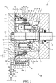
- Fig. 1 is a sectional view showing the entire configuration of a hydraulic motor 1 serving as a fluid pressure motor to which the brake system 100 is applied.
- the hydraulic motor 1 is, for example, a swash plate type hydraulic motor used for a traveling device or a turning device of a construction machine, etc.
- the hydraulic motor 1 includes an output shaft 2 coupled to a driven body (not shown) serving as a load, and a cylinder block 3 coupled to the output shaft 2 which is configured to be rotated integrally with the output shaft 2.
- the output shaft 2 is rotatably supported by a case 11 via two bearings 17, 18.
- the case 11 is divided into a housing case 12 configured to house the cylinder block 3, and a lid member 13 combined with the housing case 12 via a bolt (not shown) and configured to cover an opening portion of the housing case 12.
- Plural cylinders 4 arranged on the concentric circle centered on the axis O1 of the output shaft 2 are provided in the cylinder block 3 in parallel to the output shaft 2.
- the cylinders 4 are opened on one end surface of the cylinder block 3, and a piston 6 defining a capacity chamber 5 in the cylinder 4 is reciprocatably and slidably inserted into each of the cylinders 4.
- a spline 3a formed along the axis O1 of the output shaft 2 is provided in an outer periphery of the cylinder block 3.
- a shoe 9 is coupled to a leading end of the piston 6 via a spherical surface seat 6a.
- the shoe 9 is in surface contact with a swash plate 7 fixed to the housing case 12.
- the piston 6 reciprocates in the cylinder 4 by a stroke amount in accordance with a tilt angle of the swash plate 7 with which the shoe 9 is in sliding contact.
- a valve plate 8 in sliding contact with a base end surface of the cylinder block 3 is attached between the lid member 13 and the cylinder block 3.
- the valve plate 8 has a supply port (not shown) communicating with a hydraulic supply source (not shown), and a discharge port (not shown) communicating with the tank side.
- the pistons 6 project from the cylinders 4 by hydraulic pressure led from the hydraulic supply source to the capacity chambers 5 via the supply port, and the pistons 6 push the swash plate 7 via the shoes 9, so that the cylinder block 3 is rotated. Rotation of the cylinder block 3 is transmitted to the driven body via the output shaft 2, so that it is possible to drive the driven body.
- the hydraulic motor 1 includes the friction brake type brake system 100 configured to maintain the cylinder block 3 in a non-rotated state in order to prevent that the driven body starts moving in a state where the pressure oil is not suppled to the cylinders 4.
- the brake system 100 will be described.
- the brake system 100 includes a brake device 20 configured to cancel brake force by supply of working oil serving as a pressurized working fluid and generate the brake force by discharge of the working oil, supply passages 53, 54 through which the working oil pressurized in a hydraulic pump 51 serving as a working fluid pressurizing source is supplied to the brake device 20, a valve device 40 provided in the supply passages 53, 54 and configured to open and close the supply passages 53, 54, a discharge passage 56 through which the working oil discharged from the brake device 20 flows, and a restrictor 57 provided in the discharge passage 56 and configured to apply resistance to the working oil flowing through the discharge passage 56.
- the supply passages 53, 54 have the first supply passage 53 on the hydraulic pump 51 side serving as a supply passage on the upstream side, and the second supply passage 54 on the brake device 20 side serving as a supply passage on the downstream side.
- the valve device 40 is provided between the first supply passage 53 and the second supply passage 54.
- the working fluid is not limited to the working oil but may be an alternative soluble liquid, etc.
- the brake device 20 has plural disc plates 21 configured to be rotated together with the cylinder block 3, plural friction plates 22 non-rotatably provided in the housing case 12, the friction plates being configured to generate friction brake force between the friction plates and the disc plates 21 by being abutted with the disc plates 21, and a brake driving mechanism 25 capable of generating the friction brake force by pressing the disc plates 21 and the friction plates 22 against one another and cancelling the friction brake force by cancelling the pressing.
- the disc plates 21 are ring shaped members, and in the present embodiment, as shown in Fig. 1 , three disc plates are provided so that the disc plates are separated from each other in the axis O1 direction of the output shaft 2 and sandwich the friction plates 22.
- the disc plates 21 By meshing the teeth 21a of the disc plates 21 with the splines 3a of the cylinder block 3, the disc plates 21 can be rotated following the rotation of the cylinder block 3 and the disc plates 21 are movable in the axis O1 direction of the output shaft 2 with respect to the cylinder block 3. In such a way, the disc plates 21 are spline-fitted to the outer periphery of the cylinder block 3.
- the disc plates 21 may be spline-fitted not to the cylinder block 3 but to another member configured to be rotated together with the output shaft 2.
- the friction plates 22 are ring shaped members, and in the present embodiment, as shown in Fig. 1 , two friction plates are provided so that the friction plates are separated from each other and sandwiched by the disc plates 21 in the axis O1 direction of the output shaft 2.
- Each of the friction plates 22 has a projecting portion (not shown) extending from an outer edge toward the radially outside. This projecting portion is fitted to a spline (not shown) formed on an inner peripheral surface of the housing case 12. Therefore, the friction plates 22 are not rotatable with respect to the housing case 12, and the friction plates 22 are movable in the axis O1 direction of the output shaft 2 with respect to the housing case 12.
- a stepped portion 12c configured to regulate predetermined movement or more of the disc plates 21 and the friction plates 22 in the axis O1 direction of the output shaft 2 is formed in the housing case 12 to which the friction plates 22 are assembled.
- the plural disc plates 21 and the plural friction plates 22 are arranged in a state where the plates are laminated between the brake driving mechanism 25 and the stepped portion 12c.
- the number of the disc plates 21 is not limited to three but may be one or may be plural numbers which is other than three.
- the number of the friction plates 22 is also not limited to two but appropriately provided in accordance with the number of the disc plates 21. In a case where the number of the disc plates 21 is one, the friction plates 22 do not have to be provided.
- the brake driving mechanism 25 has an annular brake piston 27 supported by the housing case 12, the brake piston being movable in the axial direction of the output shaft 2, plural brake springs 30 serving as a piston bias member placed between the lid member 13 and the brake piston 27, the brake springs being configured to bias the brake piston 27 toward the disc plates 21, and a brake cancellation chamber 28 configured to move the brake piston 27 against bias force of the brake springs 30 by supply of the pressurized working oil.
- the brake piston 27 has a sliding portion 27a configured to slide along a first inner peripheral wall 12a of the housing case 12, and an abutment portion 27b having an outer diameter smaller than that of the sliding portion 27a and projecting from the sliding portion 27a toward the disc plates 21.
- An outer peripheral surface 27c of the abutment portion 27b slides along a second inner peripheral wall 12b having a diameter smaller than that of the first inner peripheral wall 12a.
- the brake cancellation chamber 28 is provided between the housing case 12 and the brake piston 27 that slide with respect to each other.
- the brake cancellation chamber 28 is defined by the outer peripheral surface 27c of the abutment portion 27b and the first inner peripheral wall 12a of the housing case 12.
- the second supply passage 54 for leading the working oil from the hydraulic pump 51 to the brake cancellation chamber 28 and the discharge passage 56 for leading the working oil discharged from the brake cancellation chamber 28 to a space 15 in the case 11 are formed in the housing case 12 defining the brake cancellation chamber 28.
- One end of the second supply passage 54 communicates with the brake cancellation chamber 28, and the other end is open on the outside of the housing case 12.
- One end of the discharge passage 56 communicates with the brake cancellation chamber 28, and the other end is open on the inside of the housing case 12. In such a way, the brake cancellation chamber 28 always communicates with the space 15 in the case 11 communicating with a tank 52 through the discharge passage 56.
- the restrictor 57 is provided in the discharge passage 56. Therefore, resistance in accordance with the passage sectional area of the restrictor 57 is applied to the working oil flowing from the brake cancellation chamber 28 to the space 15 in the case 11 through the discharge passage 56.
- the counter bores 27d formed on a surface opposing the lid member 13 are provided in the sliding portion 27a of the brake piston 27.
- the counter bores 27d are evenly arranged along the circumferential direction.
- Each of the brake springs 30 is accommodated in each of the counter bores 27d.
- the brake springs 30 are coil springs placed between the lid member 13 and the brake piston 27 in a compressed state.
- the brake springs bias the brake piston 27 in the direction in which the capacity of the brake cancellation chamber 28 is shrunk and generate the bias force to push the brake piston 27 to the disc plates 21.
- double springs formed by an inside spring and an outside spring may be used in order to ensure sufficient bias force.
- the valve device 40 has a valve housing 42, a spool valve 41 serving as a valve element configured to be slidably housed in a housing hole 42a formed in the valve housing 42, a closing member 44 closing one end of the housing hole 42a, and a spring 43 arranged between the closing member 44 and the spool valve 41 in a compressed state, the spring being configured to apply bias force to the spool valve 41.
- the housing hole 42a is formed, and a first connection port 55a connected to the first supply passage 53 on the hydraulic pump 51 side, the first connection port to which the working oil is led from the hydraulic pump 51, and a second connection port 55b connected to the second supply passage 54 on the brake device 20 side, the second connection port from which the working oil is led to the brake device 20 are formed.
- the first connection port 55a is formed continuously to the housing hole 42a in the axial direction, and the second connection port 55b is formed so that one end is open on a side surface of the housing hole 42a.
- the valve device 40 is assembled to the housing case 12 so that the second connection port 55b is connected to the second supply passage 54 formed in the housing case 12.
- the valve device 40 can be assembled to the case 11 only by connecting the second connection port 55b to the second supply passage 54. In such a way, the valve device 40 and the case 11 are connected only with one passage. Thus, it is possible to freely set the direction in which the valve device 40 is assembled to the case 11. As a result, it is possible to improve an assembling property of the valve device 40.
- the valve device 40 may be assembled inside the housing case 12 or may be assembled inside the lid member 13.
- the spool valve 41 is a columnar member slidably supported by the housing hole 42a, and has a pressure receiving surface 41a facing the first connection port 55a, a communication hole 41b formed along the axial direction of the spool valve 41, and an annular groove 41c formed in an annular shape on an outer peripheral surface.
- the communication hole 41b is a non-through hole in which one end is open on the pressure receiving surface 41a, and the annular groove 41c communicates with the communication hole 41b through plural holes formed in the radial direction.
- the spool valve 41 also has a land portion 41d provided on the opposite side of an opening end of the communication hole 41b with respect to the annular groove 41c.
- the land portion 41d functions as a sliding surface to slide with respect to the housing hole 42a, and also functions as a shut-off portion to shut off communication between the annular groove 41c and the second connection port 55b. That is, when the spool valve 41 is moved so that the land portion 41d is placed between the annular groove 41c and the second connection port 55b, the communication between the first connection port 55a and the second connection port 55b is shut off.
- a limiting portion configured to limit movement of the spool valve 41 may be provided so that the spool valve 41 is moved only between a position where the communication between the first connection port 55a and the second connection port 55b is permitted and a position where the communication between the first connection port 55a and the second connection port 55b is shut off.
- the hydraulic pump 51 is a pump configured to be driven by a drive source (not shown) such as an engine.
- the hydraulic pump sucks the working oil stored in the tank 52, and supplies the pressurized working oil to the brake device 20 through the supply passages 53, 54 and the valve device 40.
- the hydraulic pump 51 may also serve as a pump configured to supply the working oil to the hydraulic motor 1.
- a switching valve 58 is also provided between the hydraulic pump 51 and the valve device 40.
- the switching valve 58 is a two position electromagnetic switching valve having two positions of a brake activation position 58a where the first supply passage 53 and the tank 52 communicate with each other, and a brake cancellation position 58b where the first supply passage 53 and the hydraulic pump 51 communicate with each other.
- the switching valve 58 is switched in conjunction with operation of an operation lever (not shown) for operating the hydraulic motor 1.
- a position of the switching valve 58 is switched to the brake cancellation position 58b.
- the position of the switching valve 58 is switched to the brake activation position 58a.
- the switching valve 58 may be mechanically switched in conjunction with the operation of the operation lever.
- Fig. 1 shows a state where rotation of the hydraulic motor 1 is braked by the brake system 100.
- the pressurized working oil is led from the hydraulic pump 51 to the first connection port 55a through the first supply passage 53.
- Pressure of the working oil led to the first connection port 55a acts on the pressure receiving surface 41a of the spool valve 41, and becomes thrust force that moves the spool valve 41 against the bias force of the spring 43.
- the spool valve 41 When the pressure of the working oil led to the first connection port 55a reaches predetermined pressure, the spool valve 41 is moved to the position where the communication between the first connection port 55a and the second connection port 55b is permitted.
- the brake cancellation chamber 28 always communicates with the space 15 in the case 11 through the discharge passage 56, pressure in the brake cancellation chamber 28 is maintained to be predetermined pressure by the restrictor 57 provided in the discharge passage 56. Therefore, the brake piston 27 is held in a state where the brake piston is separated from the disc plates 21.
- the first supply passage 53 communicates with the tank 52.
- pressure in the first connection port 55a of the valve device 40 is lowered to pressure of the tank 52. Therefore, the spool valve 41 is moved to the position where the communication between the first connection port 55a and the second connection port 55b is shut off by the bias force of the spring 43.
- the friction brake force is generated between the disc plates 21 and the friction plates 22.
- the cylinder block 3 is maintained in a state where the rotation is stopped.
- valve device 40 by inhibiting the working oil from going into and out of the brake cancellation chamber 28 through the second supply passage 54 and discharging the working oil from the brake cancellation chamber 28 through the discharge passage 56, it is possible to maintain the hydraulic motor 1 in a stopped state.
- the pressure of the brake cancellation chamber 28 is relatively slowly lowered. That is, even when the position of the switching valve 58 is switched to the brake activation position 58a, the cylinder block 3 is not instantaneously completely braked but after a predetermined time elapses, the brake force is gradually increased.
- the valve device 40 provided in the supply passages 53, 54 through which the working oil supplied to the brake device 20 flows is opened by the pressure of the working oil supplied from the hydraulic pump 51 to the first connection port 55a, and permits that the working oil is supplied to the brake device 20 through the first connection port 55a and the second connection port 55b.
- valve device 40 since the valve device 40 is directly opened by the working oil supplied to the brake device 20, there is no need for separately leading pilot pressure for opening the valve device 40 to the valve device 40. Therefore, it is possible to simplify the configuration of the valve device 40, and it is possible to make the number of pipes through which the working oil is supplied to the valve device 40 only one. As a result, it is possible to reduce manufacturing cost of the brake system 100.
- the discharge passage 56 and the restrictor 57 are provided to communicate with the supply passages 53, 54 via the brake cancellation chamber 28. That is, part of the working oil supplied to the brake cancellation chamber 28 through the supply passages 53, 54 is discharged through the discharge passage 56 and the restrictor 57. Therefore, even when the air remains in the brake cancellation chamber 28 at the time of assembling the brake system 100 or when the air is mixed in the working oil supplied from the valve device 40, it is possible to discharge the air in the brake cancellation chamber 28 without performing an air vent task. As a result, it is possible to stabilize activation responsiveness of the brake system 100.
- a brake system 200 according to a second embodiment of the present invention will be described.
- different points from the first embodiment will be mainly described, and the same configurations as the first embodiment will be given the same reference signs and description thereof will be omitted.
- the basic configurations of the brake system 200 are the same as those of the brake system 100 according to the first embodiment.
- the brake system 200 is different from the brake system 100 in a point that working oil in a brake cancellation chamber 28 is discharged through a valve device 140.
- the brake system 200 includes a brake device 120 configured to cancel brake force by supply of pressurized working oil and generate the brake force by discharge of the working oil, supply passages 53, 54 through which the working oil pressurized in a hydraulic pump 51 is supplied to the brake device 120, the valve device 140 provided in the supply passages 53, 54 and configured to open and close the supply passages 53, 54, a discharge passage 60 through which the working oil discharged from the brake device 120 flows, and a restrictor 141g configured to apply resistance to the working oil flowing through the discharge passage 60.
- the brake device 120 has the same basic configurations as the brake device 20 of the brake system 100 according to the above first embodiment. However, the working oil goes into and out of the brake cancellation chamber 28 of the brake device 120 only through the second supply passage 54. In place of the discharge passage 56, the discharge passage 60 for leading the working oil discharged from the brake cancellation chamber 28 through the valve device 140 to a space 15 in a case 11 is formed in a housing case 12. One end of the discharge passage 60 is open on the outside of the housing case 12 and the other end is open on the inside of the housing case 12.
- the valve device 140 has a valve housing 142, a spool valve 141 serving as a valve element configured to be slidably housed in a housing hole 42a formed in the valve housing 142, a closing member 44 closing one end of the housing hole 42a, and a spring 43 arranged between the closing member 44 and the spool valve 141 in a compressed state, the spring being configured to apply bias force to the spool valve 141.
- the housing hole 42a, a first connection port 55a connected to the first supply passage 53, and a second connection port 55b connected to the second supply passage 54 are formed, and further, a third connection port 55c connected to the discharge passage 60, the third connection port from which the working oil is led to the space 15 in the case 11 is formed.
- the third connection port 55c is formed so that one end is open on a side surface of the housing hole 42a.
- the valve device 140 is assembled to the housing case 12 so that the second connection port 55b is connected to the second supply passage 54 formed in the housing case 12 and the third connection port 55c is connected to the discharge passage 60 formed in the housing case 12.
- the spool valve 141 has a communication hole 41b, an annular groove 41c communicating with the communication hole 41b, and a land portion 41d, and also has a discharge hole 141e serving as an exhaust passage formed along the axial direction on the opposite side of the communication hole 41b, a discharge groove 141f serving as an exhaust passage formed in an annular shape on an outer peripheral surface on the opposite side of the annular groove 41c with respect to the land portion 41d, and the restrictor 141g providing communication between the discharge hole 141e and the discharge groove 141f.
- the discharge hole 141e is a non-through hole open on an end surface on the opposite side of an end surface on which the communication hole 41b is open.
- a position where the restrictor 141g is provided is not limited to the position where the discharge hole 141e and the discharge groove 141f communicate with each other but may be in an opening end of the discharge hole 141e, in the third connection port 55c, or in the discharge passage 60.
- a limiting portion configured to limit movement of the spool valve 141 may be provided so that the spool valve 141 is moved only between a position where the communication between the first connection port 55a and the second connection port 55b is permitted and a position where communication between the second connection port 55b and the third connection port 55c is permitted.
- the first supply passage 53 communicates with a tank 52.
- pressure in the first connection port 55a of the valve device 140 is lowered to pressure of the tank 52. Therefore, the spool valve 141 is moved to a position where the communication between the first connection port 55a and the second connection port 55b is shut off and the communication between the second connection port 55b and the third connection port 55c is permitted by the bias force of the spring 43.
- valve device 140 by inhibiting supply of the working oil to the brake cancellation chamber 28 through the second supply passage 54 and discharging the working oil from the brake cancellation chamber 28 through the second supply passage 54, it is possible to maintain the hydraulic motor 1 in a stopped state.
- the restrictor 141g is provided in the spool valve 141 of the valve device 140 through which the working oil discharged from the brake cancellation chamber 28 flows, as well as the above first embodiment, the pressure of the brake cancellation chamber 28 is relatively slowly lowered, and even when the position of the switching valve 58 is switched to the brake activation position 58a, the cylinder block 3 is not instantaneously completely braked but after a predetermined time elapses, brake force is gradually increased.
- the valve device 140 provided in the supply passages 53, 54 through which the working oil supplied to the brake device 120 flows is opened by the pressure of the working oil supplied from the hydraulic pump 51 to the first connection port 55a, and permits that the working oil is supplied to the brake device 120 through the first connection port 55a and the second connection port 55b.
- valve device 140 since the valve device 140 is directly opened by the working oil supplied to the brake device 120, there is no need for separately leading pilot pressure for opening the valve device 140 to the valve device 140. Therefore, it is possible to simplify the configuration of the valve device 140, and it is possible to make the number of pipes through which the working oil is supplied to the valve device 140 only one. As a result, it is possible to reduce manufacturing cost of the brake system 200.
- the discharge passage 141e and the restrictor 141g are provided in the valve element 141. Since the discharge passage 141e and the restrictor 141g are provided in the valve element 141 of the valve device 140 in such a way, by replacing the valve element 141 or the valve device 140, it is possible to easily adjust an activation delay time at the time of generating the brake force by the brake system 200.
- the working oil discharged from the brake cancellation chamber 28 through the discharge hole 141e formed in the spool valve 141 is led to the space 15 in the case 11 by the third connection port 55c and the discharge passage 60.
- the working oil discharged from the brake cancellation chamber 28 through the discharge hole 141e may be directly led to the tank 52.
- a brake system 300 according to a third embodiment of the present invention will be described.
- different points from the first embodiment will be mainly described, and the same configurations as the first embodiment will be given the same reference signs and description thereof will be omitted.
- the basic configurations of the brake system 300 are the same as those of the brake system 100 according to the first embodiment.
- the brake system 300 is different from the brake system 100 in a point that a valve element of a valve device 240 is a poppet valve 241 and a point that a discharge passage 61 is formed in a brake piston 27.
- the brake system 300 includes a brake device 220 configured to cancel brake force by supply of pressurized working oil and generate the brake force by discharge of the working oil, supply passages 53, 54 through which the working oil pressurized in a hydraulic pump 51 is supplied to the brake device 220, the valve device 240 provided in the supply passages 53, 54 and configured to open and close the supply passages 53, 54, the discharge passage 61 through which the working oil discharged from the brake device 220 flows, and a restrictor 62 provided in the discharge passage 61 and configured to apply resistance to the working oil flowing through the discharge passage 61.
- the brake device 220 has the same basic configurations as the brake device 20 of the brake system 100 according to the above first embodiment.
- the discharge passage 61 for leading the working oil discharged from a brake cancellation chamber 28 to a space 15 in a case 11 is provided not in a housing case 12 but in the brake piston 27.
- One end of the discharge passage 61 communicates with the brake cancellation chamber 28 and the other end is open on a surface facing the space 15 in the case 11. In such a way, the brake cancellation chamber 28 always communicates with the space 15 in the case 11 communicating with a tank 52 through the discharge passage 61.
- the restrictor 62 is provided in the discharge passage 61. Therefore, resistance in accordance with the passage sectional area of the restrictor 62 is applied to the working oil flowing from the brake cancellation chamber 28 to the space 15 in the case 11 through the discharge passage 61.
- the valve device 240 has a valve housing 242, the poppet valve 241 serving as a valve element configured to be slidably housed in a housing hole 242a formed in the valve housing 242, a closing member 44 closing one end of the housing hole 242a, and a spring 43 arranged between the closing member 44 and the poppet valve 241 in a compressed state, the spring being configured to apply bias force to the poppet valve 241.
- the housing hole 242a is formed, and a valve seat portion 242b from and in which the poppet valve 241 is separated and seated, a first connection port 55a connected to the first supply passage 53 on the hydraulic pump 51 side, the first connection port to which the working oil is led from the hydraulic pump 51, and a second connection port 55b connected to the second supply passage 54 on the brake device 220 side, the second connection port from which the working oil is led to the brake device 220 are formed.
- the first connection port 55a is formed continuously to the housing hole 242a in the axial direction
- the valve seat portion 242b is formed between the housing hole 242a and the first connection port 55a
- the second connection port 55b is formed so that one end is open on a side surface of the housing hole 242a.
- the valve device 240 is assembled to the housing case 12 so that the second connection port 55b is connected to the second supply passage 54 formed in the housing case 12.
- the valve device 240 can be assembled to the case 11 only by connecting the second connection port 55b to the second supply passage 54. In such a way, the valve device 240 and the case 11 are connected only with one passage. Thus, it is possible to freely set the direction in which the valve device 240 is assembled to the case 11. As a result, it is possible to improve an assembling property of the valve device 240.
- the poppet valve 241 has a pressure receiving surface 241a facing the first connection port 55a, a valve portion 241b provided in a periphery of the pressure receiving surface 241a, the valve portion being configured to be separated from and seated in the valve seat portion 242b, a cylindrical sliding portion 241c slidably supported by the housing hole 242a, and a small diameter portion 241d formed on an outer peripheral surface between the valve portion 241b and the sliding portion 241c.
- the small diameter portion 241d has an outer diameter smaller than that of the sliding portion 241c, and a clearance is formed between the small diameter portion 241d and the housing hole 242a.
- the small diameter portion 241d is provided between the valve portion 241b and the sliding portion 241c in the poppet valve 241.
- the first connection port 55a and the second connection port 55b communicate with each other through a clearance between the valve portion 241b and the valve seat portion 242b and the clearance between the small diameter portion 241d and the housing hole 242a.
- the valve portion 241b is seated in the valve seat portion 242b, communication between the first connection port 55a and the second connection port 55b is shut off.
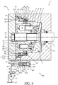
- Fig. 3 shows a state where rotation of a hydraulic motor 1 is braked by the brake system 300.
- the poppet valve 241 When the pressure of the working oil led to the first connection port 55a reaches predetermined pressure, the poppet valve 241 is moved in the direction in which the valve portion 241b is separated from the valve seat portion 242b, that is, in the direction in which the communication between the first connection port 55a and the second connection port 55b is permitted.
- the pressurized working oil is supplied from the hydraulic pump 51 to the brake cancellation chamber 28 through the first supply passage 53, the valve device 240, and the second supply passage 54.
- the brake cancellation chamber 28 always communicates with the space 15 in the case 11 through the discharge passage 61, pressure in the brake cancellation chamber 28 is maintained to be predetermined pressure by the restrictor 62 provided in the discharge passage 61. Therefore, the brake piston 27 is held in a state where the brake piston is separated from the disc plates 21.
- the first supply passage 53 communicates with the tank 52.
- pressure in the first connection port 55a of the valve device 240 is lowered to pressure of the tank 52. Therefore, the poppet valve 241 is moved in the direction in which the valve portion 241b is seated in the valve seat portion 242b, that is, to a position where the communication between the first connection port 55a and the second connection port 55b is shut off by the bias force of the spring 43.
- the friction brake force is generated between the disc plates 21 and the friction plates 22.
- the cylinder block 3 is maintained in a state where the rotation is stopped.
- valve device 240 by inhibiting the working oil from going into and out of the brake cancellation chamber 28 through the second supply passage 54 and discharging the working oil from the brake cancellation chamber 28 through the discharge passage 61, it is possible to maintain the hydraulic motor 1 in a stopped state.
- the pressure of the brake cancellation chamber 28 is relatively slowly lowered. That is, even when the position of the switching valve 58 is switched to the brake activation position 58a, the cylinder block 3 is not instantaneously completely braked but after a predetermined time elapses, the brake force is gradually increased.
- the valve device 240 provided in the supply passages 53, 54 through which the working oil supplied to the brake device 220 flows is opened by the pressure of the working oil supplied from the hydraulic pump 51 to the first connection port 55a, and permits that the working oil is supplied to the brake device 220 through the first connection port 55a and the second connection port 55b.
- valve device 240 since the valve device 240 is directly opened by the working oil supplied to the brake device 220, there is no need for separately leading pilot pressure for opening the valve device 240 to the valve device 240. Therefore, it is possible to simplify the configuration of the valve device 240, and it is possible to make the number of pipes through which the working oil is supplied to the valve device 240 only one. As a result, it is possible to reduce manufacturing cost of the brake system 300.
- the discharge passage 61 and the restrictor 62 are provided to communicate with the supply passages 53, 54 via the brake cancellation chamber 28. That is, part of the working oil supplied to the brake cancellation chamber 28 through the supply passages 53, 54 is discharged through the discharge passage 61 and the restrictor 62. Therefore, even when the air remains in the brake cancellation chamber 28 at the time of assembling the brake system 300 or when the air is mixed in the working oil supplied from the valve device 240, it is possible to discharge the air in the brake cancellation chamber 28 without performing an air vent task. As a result, it is possible to stabilize activation responsiveness of the brake system 300.
- the discharge passage 61 and the restrictor 62 are provided in the brake piston 27.
- the discharge passage 61 and the restrictor 62 may be provided in the housing case 12 as well as the above first embodiment.
- the discharge passage 56 and the restrictor 57 of the brake system 100 according to the above first embodiment may be provided in the brake piston 27 as well as the above third embodiment.
- a brake system 400 according to a fourth embodiment of the present invention will be described.
- different points from the third embodiment will be mainly described, and the same configurations as the third embodiment will be given the same reference signs and description thereof will be omitted.
- the basic configurations of the brake system 400 are the same as those of the brake system 300 according to the third embodiment.
- the brake system 400 is different from the brake system 300 in a point that working oil in a brake cancellation chamber 28 is discharged through a valve device 340.
- the brake system 400 includes a brake device 320 configured to cancel brake force by supply of pressurized working oil and generate the brake force by discharge of the working oil, supply passages 53, 54 through which the working oil pressurized in a hydraulic pump 51 is supplied to the brake device 320, the valve device 340 provided in the supply passages 53, 54 and configured to open and close the supply passages 53, 54, a discharge passage 60 through which the working oil discharged from the brake device 320 flows, and a restrictor 341f configured to apply resistance to the working oil flowing through the discharge passage 60.
- the brake device 320 has the same basic configurations as the brake device 220 of the brake system 300 according to the above third embodiment. However, the working oil goes into and out of the brake cancellation chamber 28 of the brake device 320 only through the second supply passage 54.
- the discharge passage 60 for leading the working oil discharged from the brake cancellation chamber 28 through the valve device 340 to a space 15 in a case 11 is formed in a housing case 12. One end of the discharge passage 60 is open on the outside of the housing case 12 and the other end is open on the inside of the housing case 12.
- the valve device 340 has a valve housing 342, a poppet valve 341 serving as a valve element configured to be slidably housed in a housing hole 242a formed in the valve housing 342, a closing member 44 closing one end of the housing hole 242a, and a spring 43 arranged between the closing member 44 and the poppet valve 341 in a compressed state, the spring being configured to apply bias force to the poppet valve 341.
- the third connection port 55c is formed so that one end is open on a side surface of the housing hole 242a.
- the valve device 340 is assembled to the housing case 12 so that the second connection port 55b is connected to the second supply passage 54 formed in the housing case 12 and the third connection port 55c is connected to the discharge passage 60 formed in the housing case 12.
- the poppet valve 341 has a valve portion 241b, a sliding portion 241c, and a small diameter portion 241d formed between the valve portion 241b and the sliding portion 241c, and also has a discharge hole 341e serving as a discharge passage formed along the axial direction on the opposite side of the valve portion 241b, and the restrictor 341f providing communication between a clearance between the small diameter portion 241d and the housing hole 242a and the discharge hole 341e.
- the discharge hole 341e is a non-through hole open on an end surface on the opposite side of an end surface on which the valve portion 241b is formed.
- valve portion 241b of the poppet valve 341 having the above configuration When the valve portion 241b of the poppet valve 341 having the above configuration is seated in the valve seat portion 242b, communication between the first connection port 55a and the second connection port 55b is shut off, while the second connection port 55b and the third connection port 55c communicate with each other through the discharge hole 341e and the restrictor 341f.
- the restrictor 341f By providing the restrictor 341f, resistance in accordance with the passage sectional area of the restrictor 341f is applied to the working oil flowing between the second connection port 55b and the third connection port 55c.
- the third connection port 55c is provided at a position where the third connection port is not closed by the sliding portion 241c at the time of seating the valve portion 241b of the poppet valve 341 in the valve seat portion 242b.
- the first supply passage 53 communicates with a tank 52.
- pressure in the first connection port 55a of the valve device 340 is lowered to pressure of the tank 52. Therefore, the poppet valve 341 is moved in the direction in which the valve portion 241b is seated in the valve seat portion 242b, that is, to a position where the communication between the first connection port 55a and the second connection port 55b is shut off by the bias force of the spring 43.
- valve device 340 by inhibiting supply of the working oil to the brake cancellation chamber 28 through the second supply passage 54 and discharging the working oil from the brake cancellation chamber 28 through the second supply passage 54, it is possible to maintain the hydraulic motor 1 in a stopped state.
- the restrictor 341f is provided in the poppet valve 341 of the valve device 340 through which the working oil discharged from the brake cancellation chamber 28 flows, as well as the above third embodiment, the pressure of the brake cancellation chamber 28 is relatively slowly lowered, and even when the position of the switching valve 58 is switched to the brake activation position 58a, the cylinder block 3 is not instantaneously completely braked but after a predetermined time elapses, brake force is gradually increased.
- the valve device 340 provided in the supply passages 53, 54 through which the working oil supplied to the brake device 320 flows is opened by the pressure of the working oil supplied from the hydraulic pump 51 to the first connection port 55a, and permits that the working oil is supplied to the brake device 320 through the first connection port 55a and the second connection port 55b.
- valve device 340 since the valve device 340 is directly opened by the working oil supplied to the brake device 320, there is no need for separately leading pilot pressure for opening the valve device 340 to the valve device 340. Therefore, it is possible to simplify the configuration of the valve device 340, and it is possible to make the number of pipes through which the working oil is supplied to the valve device 340 only one. As a result, it is possible to reduce manufacturing cost of the brake system 400.
- the discharge passage 341e and the restrictor 341f are provided in the valve element 341. Since the discharge passage 341e and the restrictor 341f are provided in the valve element 341 of the valve device 340 in such a way, by replacing the valve element 341 or the valve device 340, it is possible to easily adjust an activation delay time at the time of generating the brake force by the brake system 400.
- the working oil discharged from the brake cancellation chamber 28 through the discharge hole 341e formed in the poppet valve 341 is led to the space 15 in the case 11 by the third connection port 55c and the discharge passage 60.
- the working oil discharged from the brake cancellation chamber 28 through the discharge hole 341e may be directly led to the tank 52.
- the brake system 100, 200, 300, 400 includes the brake device 20, 120, 220, 320 configured to cancel the brake force by supply of the pressurized working oil and generate the brake force by discharge of the working oil, the supply passages 53, 54 through which the working oil pressurized in the hydraulic pump 51 is supplied to the brake device 20, 120, 220, 320, the valve device 40, 140, 240, 340 provided in the supply passages 53, 54 and configured to open and close the supply passages 53, 54, the discharge passage 56, 60, 61 through which the working oil discharged from the brake device 20, 120, 220, 320 flows, and the restrictor 57, 62, 141g, 341f configured to apply resistance to the working oil flowing through the discharge passage 56, 60, 61.
- the valve device 40, 140, 240, 340 has the first connection port 55a connected to the upstream side of the supply passages 53, 54, the first connection port to which the working oil is led from the hydraulic pump 51, the second connection port 55b connected to the downstream side of the supply passages 53, 54, the second connection port from which the working oil is led to the brake device 20, 120, 220, 320, and the valve element 41, 141, 241, 341 provided with the pressure receiving surface 41a, 241a facing the first connection port 55a, and the valve element 41, 141, 241, 341 permits the communication between the first connection port 55a and the second connection port 55b when the pressure of the working oil led to the first connection port 55a reaches the predetermined pressure, and shuts off the communication between the first connection port 55a and the second connection port 55b when the pressure of the working oil led to the first connection port 55a becomes less than the predetermined pressure.
- valve device 40, 140, 240, 340 provided in the supply passages 53, 54 through which the working oil supplied to the brake device 20, 120, 220, 320 flows is opened by the pressure of the working oil supplied from the hydraulic pump 51 to the first connection port 55a, and permits that the working oil is supplied to the brake device 20, 120, 220, 320 through the first connection port 55a and the second connection port 55b.
- valve device 40, 140, 240, 340 is directly opened by the working oil supplied to the brake device 20, 120, 220, 320, there is no need for separately leading pilot pressure for opening the valve device 40, 140, 240, 340 to the valve device 40, 140, 240, 340. Therefore, it is possible to simplify the configuration of the valve device 40, 140, 240, 340, and it is possible to make the number of pipes through which the working oil is supplied to the valve device 40, 140, 240, 340 only one. As a result, it is possible to reduce the manufacturing cost of the brake system 100, 200, 300, 400.
- the valve element 41, 141 is the spool valve having the communication hole 41b open on the pressure receiving surface 41a, and the annular groove 41c formed on the outer peripheral surface, the annular groove communicating with the communication hole 41b, and by moving the valve element 41, 141 to the position where the annular groove 41c and the second connection port 55b oppose each other by the pressure of the working oil led to the first connection port 55a, the communication between the first connection port 55a and the second connection port 55b is permitted.
- the valve device 40, 140 supplies the working oil to the brake device 20, 120 through the communication hole 41b open on the pressure receiving surface 41a on which the pressure of the working oil to open the valve element 41, 141 acts. That is, there is no need for separately leading pilot pressure for opening the valve device 40, 140 to the valve device 40, 140. Therefore, it is possible to simplify the configuration of the valve device 40, 140, and it is possible to make the number of pipes through which the working oil is supplied to the valve device 40, 140 only one. As a result, it is possible to reduce the manufacturing cost of the brake system 100, 200.
- the valve element 241, 341 is the poppet valve having the valve portion 241b provided in the periphery of the pressure receiving surface 241a, the valve portion being configured to be separated from and seated in the valve seat portion 242b, and by moving the valve element 241, 341 in the direction in which the valve portion 241b is separated from the valve seat portion 242b by the pressure of the working oil led to the first connection port 55a, the communication between the first connection port 55a and the second connection port 55b is permitted.
- the first connection port 55a and the second connection port 55b communicate with each other through the clearance between the valve portion 241b provided in the periphery of the pressure receiving surface 241a and the valve seat portion 242b.
- the valve device 240, 340 supplies the working oil to the brake device 220, 320 via the valve portion 241b provided in the periphery of the pressure receiving surface 241a on which the pressure of the working oil to open the valve element 241, 341 acts. That is, there is no need for separately leading pilot pressure for opening the valve device 240, 340 to the valve device 240, 340.
- valve device 240, 340 it is possible to simplify the configuration of the valve device 240, 340, and it is possible to make the number of pipes through which the working oil is supplied to the valve device 240, 340 only one. As a result, it is possible to reduce the manufacturing cost of the brake system 300, 400.
- the brake device 20, 220 has the disc plates 21 configured to be rotated together with the cylinder block 3, the brake piston 27 supported by the housing case 12 slidably and movably in the axial direction of the output shaft 2, the brake springs 30 configured to generate the bias force that biases the brake piston 27 toward the disc plates 21, and the brake cancellation chamber 28 defined by the brake piston 27 and the housing case 12, the brake cancellation chamber being configured to move the brake piston 27 against the bias force of the brake springs 30 by supply of the working oil, the discharge passage 56, 61 and the restrictor 57, 62 are provided in the brake piston 27 or the housing case 12 defining the brake cancellation chamber 28, and the supply passages 53, 54 and the discharge passage 56, 61 communicate with each other via the brake cancellation chamber 28.
- the discharge passage 56, 61 and the restrictor 57, 62 are provided to communicate with the supply passages 53, 54 via the brake cancellation chamber 28. That is, part of the working oil supplied to the brake cancellation chamber 28 through the supply passages 53, 54 is discharged through the discharge passage 56, 61 and the restrictor 57, 62. Therefore, even when the air remains in the brake cancellation chamber 28 at the time of assembling the brake system 100, 300 or when the air is mixed in the working oil supplied from the valve device 40, 240, it is possible to discharge the air in the brake cancellation chamber 28 without performing an air vent task. As a result, it is possible to stabilize the activation responsiveness of the brake system 100, 300.
- the discharge passage 141e, 341e and the restrictor 141g, 341f are provided in the valve element 141, 341, and when the communication between the first connection port 55a and the second connection port 55b is shut off by the valve element 141, 341, the discharge passage 141e, 341e communicates with the second connection port 55b.
- the discharge passage 141e, 341e and the restrictor 141g, 341f are provided in the valve element 141, 341. Since the discharge passage 141e, 341e and the restrictor 141g, 341f are provided in the valve element 141, 341 of the valve device 140, 340 in such a way, by replacing the valve element 141, 341, it is possible to easily adjust the activation delay time at the time of generating the brake force by the brake system 200, 400.
- the hydraulic motor 1 includes the brake system 100, 200, 300, 400 having the above configuration.
- the hydraulic motor 1 includes the brake system 100, 200, 300, 400 having the above configuration.
- the brake system 100, 200, 300, 400 having the above configuration it is possible to make the number of pipes through which the working oil is supplied to the valve device 40, 140, 240, 340 only one. As a result, it is possible to reduce manufacturing cost of the hydraulic motor 1 including the brake system 100, 200, 300, 400.
Landscapes
- Engineering & Computer Science (AREA)
- General Engineering & Computer Science (AREA)
- Mechanical Engineering (AREA)
- Chemical & Material Sciences (AREA)
- Combustion & Propulsion (AREA)
- Physics & Mathematics (AREA)
- Electromagnetism (AREA)
- Hydraulic Motors (AREA)
- Braking Arrangements (AREA)
Abstract
Description
- The present invention relates to a brake system and a fluid pressure motor including the same.
-
JP2002-039047A - The switching valve of the brake system described in
JP2002-039047A - Therefore, the number of pipes and parts that connect the pipes is increased, and the man-hour of processing the switching valve, the man-hour of connecting the pipes, etc. are increased. Thus, there is a possibility that manufacturing cost of the brake system is increased.
- An object of the present invention is to reduce manufacturing cost of a brake system.
- According to an aspect of the present invention, a brake system used in a fluid pressure motor including a cylinder block configured to be rotated by fluid pressure, an output shaft configured to be rotated integrally with the cylinder block, and a case configured to rotatably support the output shaft, the brake system includes: a brake device configured to cancel brake force by supply of a pressurized working fluid and generate the brake force by discharge of the working fluid; a supply passage through which the working fluid pressurized in a working fluid pressurizing source is supplied to the brake device; a valve device configured to open and close the supply passage; a discharge passage through which the working fluid discharged from the brake device flows; and a restrictor configured to apply resistance to the working fluid flowing through the discharge passage, wherein the valve device has a first connection port connected to the upstream side of the supply passage, the first connection port to which the working fluid is led from the working fluid pressurizing source, a second connection port connected to the downstream side of the supply passage, the second connection port from which the working fluid is led to the brake device, and a valve element provided with a pressure receiving surface facing the first connection port, and the valve element permits communication between the first connection port and the second connection port when pressure of the working fluid led to the first connection port reaches predetermined pressure, and shuts off the communication between the first connection port and the second connection port when the pressure of the working fluid led to the first connection port becomes less than the predetermined pressure.
-
- [
Fig. 1] Fig. 1 is a sectional view showing the entire configuration of a hydraulic motor to which a brake system according to a first embodiment of the present invention is applied. - [
Fig. 2] Fig. 2 is a sectional view showing the entire configuration of a hydraulic motor to which a brake system according to a second embodiment of the present invention is applied. - [
Fig. 3] Fig. 3 is a sectional view showing the entire configuration of a hydraulic motor to which a brake system according to a third embodiment of the present invention is applied. - [
Fig. 4] Fig. 4 is a sectional view showing the entire configuration of a hydraulic motor to which a brake system according to a fourth embodiment of the present invention is applied. - Hereinafter, embodiments of the present invention will be described with reference to the drawings.
- With reference to
Fig. 1 , abrake system 100 serving as an embodiment of the present invention will be described.Fig. 1 is a sectional view showing the entire configuration of a hydraulic motor 1 serving as a fluid pressure motor to which thebrake system 100 is applied. - First, the entire configuration of the hydraulic motor 1 will be described with reference to
Fig. 1 . The hydraulic motor 1 is, for example, a swash plate type hydraulic motor used for a traveling device or a turning device of a construction machine, etc. - The hydraulic motor 1 includes an
output shaft 2 coupled to a driven body (not shown) serving as a load, and acylinder block 3 coupled to theoutput shaft 2 which is configured to be rotated integrally with theoutput shaft 2. Theoutput shaft 2 is rotatably supported by acase 11 via twobearings case 11 is divided into ahousing case 12 configured to house thecylinder block 3, and alid member 13 combined with thehousing case 12 via a bolt (not shown) and configured to cover an opening portion of thehousing case 12. -
Plural cylinders 4 arranged on the concentric circle centered on the axis O1 of theoutput shaft 2 are provided in thecylinder block 3 in parallel to theoutput shaft 2. Thecylinders 4 are opened on one end surface of thecylinder block 3, and apiston 6 defining acapacity chamber 5 in thecylinder 4 is reciprocatably and slidably inserted into each of thecylinders 4. Aspline 3a formed along the axis O1 of theoutput shaft 2 is provided in an outer periphery of thecylinder block 3. - A
shoe 9 is coupled to a leading end of thepiston 6 via aspherical surface seat 6a. Theshoe 9 is in surface contact with aswash plate 7 fixed to thehousing case 12. Thepiston 6 reciprocates in thecylinder 4 by a stroke amount in accordance with a tilt angle of theswash plate 7 with which theshoe 9 is in sliding contact. - A
valve plate 8 in sliding contact with a base end surface of thecylinder block 3 is attached between thelid member 13 and thecylinder block 3. Thevalve plate 8 has a supply port (not shown) communicating with a hydraulic supply source (not shown), and a discharge port (not shown) communicating with the tank side. Thepistons 6 project from thecylinders 4 by hydraulic pressure led from the hydraulic supply source to thecapacity chambers 5 via the supply port, and thepistons 6 push theswash plate 7 via theshoes 9, so that thecylinder block 3 is rotated. Rotation of thecylinder block 3 is transmitted to the driven body via theoutput shaft 2, so that it is possible to drive the driven body. - In the hydraulic motor 1 having the above configuration, when supply of the pressure oil to the
cylinders 4 is stopped, force of pushing theswash plate 7 by thepistons 6 via theshoes 9 is eliminated, and the rotation of thecylinder block 3 is stopped. As a result, drive of the driven body is also stopped. - However, in a case where external force such as gravity force acts on the driven body configured to be driven by the hydraulic motor 1 and force corresponding to the external force is transmitted to the
cylinder block 3 via theoutput shaft 2, it is not possible to maintain thecylinder block 3 in a non-rotated state only by stopping the supply of the pressure oil to thecylinders 4. As a result, there is a possibility that the driven body starts moving. - Therefore, the hydraulic motor 1 includes the friction brake
type brake system 100 configured to maintain thecylinder block 3 in a non-rotated state in order to prevent that the driven body starts moving in a state where the pressure oil is not suppled to thecylinders 4. Hereinafter, thebrake system 100 will be described. - The
brake system 100 includes abrake device 20 configured to cancel brake force by supply of working oil serving as a pressurized working fluid and generate the brake force by discharge of the working oil,supply passages hydraulic pump 51 serving as a working fluid pressurizing source is supplied to thebrake device 20, avalve device 40 provided in thesupply passages supply passages discharge passage 56 through which the working oil discharged from thebrake device 20 flows, and arestrictor 57 provided in thedischarge passage 56 and configured to apply resistance to the working oil flowing through thedischarge passage 56. Thesupply passages first supply passage 53 on thehydraulic pump 51 side serving as a supply passage on the upstream side, and thesecond supply passage 54 on thebrake device 20 side serving as a supply passage on the downstream side. Thevalve device 40 is provided between thefirst supply passage 53 and thesecond supply passage 54. The working fluid is not limited to the working oil but may be an alternative soluble liquid, etc. - The
brake device 20 hasplural disc plates 21 configured to be rotated together with thecylinder block 3,plural friction plates 22 non-rotatably provided in thehousing case 12, the friction plates being configured to generate friction brake force between the friction plates and thedisc plates 21 by being abutted with thedisc plates 21, and abrake driving mechanism 25 capable of generating the friction brake force by pressing thedisc plates 21 and thefriction plates 22 against one another and cancelling the friction brake force by cancelling the pressing. - The
disc plates 21 are ring shaped members, and in the present embodiment, as shown inFig. 1 , three disc plates are provided so that the disc plates are separated from each other in the axis O1 direction of theoutput shaft 2 and sandwich thefriction plates 22. On the inner peripheral side of each of thedisc plates 21,plural teeth 21a configured to be meshed withsplines 3a formed in the outer periphery of thecylinder block 3 are provided. - By meshing the
teeth 21a of thedisc plates 21 with thesplines 3a of thecylinder block 3, thedisc plates 21 can be rotated following the rotation of thecylinder block 3 and thedisc plates 21 are movable in the axis O1 direction of theoutput shaft 2 with respect to thecylinder block 3. In such a way, thedisc plates 21 are spline-fitted to the outer periphery of thecylinder block 3. Thedisc plates 21 may be spline-fitted not to thecylinder block 3 but to another member configured to be rotated together with theoutput shaft 2. - The
friction plates 22 are ring shaped members, and in the present embodiment, as shown inFig. 1 , two friction plates are provided so that the friction plates are separated from each other and sandwiched by thedisc plates 21 in the axis O1 direction of theoutput shaft 2. Each of thefriction plates 22 has a projecting portion (not shown) extending from an outer edge toward the radially outside. This projecting portion is fitted to a spline (not shown) formed on an inner peripheral surface of thehousing case 12. Therefore, thefriction plates 22 are not rotatable with respect to thehousing case 12, and thefriction plates 22 are movable in the axis O1 direction of theoutput shaft 2 with respect to thehousing case 12. - A
stepped portion 12c configured to regulate predetermined movement or more of thedisc plates 21 and thefriction plates 22 in the axis O1 direction of theoutput shaft 2 is formed in thehousing case 12 to which thefriction plates 22 are assembled. Theplural disc plates 21 and theplural friction plates 22 are arranged in a state where the plates are laminated between thebrake driving mechanism 25 and thestepped portion 12c. The number of thedisc plates 21 is not limited to three but may be one or may be plural numbers which is other than three. The number of thefriction plates 22 is also not limited to two but appropriately provided in accordance with the number of thedisc plates 21. In a case where the number of thedisc plates 21 is one, thefriction plates 22 do not have to be provided. - The
brake driving mechanism 25 has anannular brake piston 27 supported by thehousing case 12, the brake piston being movable in the axial direction of theoutput shaft 2,plural brake springs 30 serving as a piston bias member placed between thelid member 13 and thebrake piston 27, the brake springs being configured to bias thebrake piston 27 toward thedisc plates 21, and abrake cancellation chamber 28 configured to move thebrake piston 27 against bias force of thebrake springs 30 by supply of the pressurized working oil. - The
brake piston 27 has a slidingportion 27a configured to slide along a first innerperipheral wall 12a of thehousing case 12, and anabutment portion 27b having an outer diameter smaller than that of the slidingportion 27a and projecting from the slidingportion 27a toward thedisc plates 21. An outerperipheral surface 27c of theabutment portion 27b slides along a second innerperipheral wall 12b having a diameter smaller than that of the first innerperipheral wall 12a. - In such a way, the
brake cancellation chamber 28 is provided between thehousing case 12 and thebrake piston 27 that slide with respect to each other. Specifically, thebrake cancellation chamber 28 is defined by the outerperipheral surface 27c of theabutment portion 27b and the first innerperipheral wall 12a of thehousing case 12. - The
second supply passage 54 for leading the working oil from thehydraulic pump 51 to thebrake cancellation chamber 28 and thedischarge passage 56 for leading the working oil discharged from thebrake cancellation chamber 28 to aspace 15 in thecase 11 are formed in thehousing case 12 defining thebrake cancellation chamber 28. One end of thesecond supply passage 54 communicates with thebrake cancellation chamber 28, and the other end is open on the outside of thehousing case 12. One end of thedischarge passage 56 communicates with thebrake cancellation chamber 28, and the other end is open on the inside of thehousing case 12. In such a way, thebrake cancellation chamber 28 always communicates with thespace 15 in thecase 11 communicating with atank 52 through thedischarge passage 56. - The restrictor 57 is provided in the
discharge passage 56. Therefore, resistance in accordance with the passage sectional area of the restrictor 57 is applied to the working oil flowing from thebrake cancellation chamber 28 to thespace 15 in thecase 11 through thedischarge passage 56. - Plural counter bores 27d formed on a surface opposing the
lid member 13 are provided in the slidingportion 27a of thebrake piston 27. The counter bores 27d are evenly arranged along the circumferential direction. Each of the brake springs 30 is accommodated in each of the counter bores 27d. - The brake springs 30 are coil springs placed between the
lid member 13 and thebrake piston 27 in a compressed state. The brake springs bias thebrake piston 27 in the direction in which the capacity of thebrake cancellation chamber 28 is shrunk and generate the bias force to push thebrake piston 27 to thedisc plates 21. As the brake springs 30, double springs formed by an inside spring and an outside spring may be used in order to ensure sufficient bias force. - The
valve device 40 has avalve housing 42, aspool valve 41 serving as a valve element configured to be slidably housed in ahousing hole 42a formed in thevalve housing 42, a closingmember 44 closing one end of thehousing hole 42a, and aspring 43 arranged between the closingmember 44 and thespool valve 41 in a compressed state, the spring being configured to apply bias force to thespool valve 41. - In the
valve housing 42, thehousing hole 42a is formed, and afirst connection port 55a connected to thefirst supply passage 53 on thehydraulic pump 51 side, the first connection port to which the working oil is led from thehydraulic pump 51, and asecond connection port 55b connected to thesecond supply passage 54 on thebrake device 20 side, the second connection port from which the working oil is led to thebrake device 20 are formed. - The
first connection port 55a is formed continuously to thehousing hole 42a in the axial direction, and thesecond connection port 55b is formed so that one end is open on a side surface of thehousing hole 42a. Thevalve device 40 is assembled to thehousing case 12 so that thesecond connection port 55b is connected to thesecond supply passage 54 formed in thehousing case 12. - Since the
discharge passage 56 is formed to communicate with thespace 15 as described above, thevalve device 40 can be assembled to thecase 11 only by connecting thesecond connection port 55b to thesecond supply passage 54. In such a way, thevalve device 40 and thecase 11 are connected only with one passage. Thus, it is possible to freely set the direction in which thevalve device 40 is assembled to thecase 11. As a result, it is possible to improve an assembling property of thevalve device 40. Thevalve device 40 may be assembled inside thehousing case 12 or may be assembled inside thelid member 13. - The
spool valve 41 is a columnar member slidably supported by thehousing hole 42a, and has apressure receiving surface 41a facing thefirst connection port 55a, acommunication hole 41b formed along the axial direction of thespool valve 41, and anannular groove 41c formed in an annular shape on an outer peripheral surface. Thecommunication hole 41b is a non-through hole in which one end is open on thepressure receiving surface 41a, and theannular groove 41c communicates with thecommunication hole 41b through plural holes formed in the radial direction. - When the
spool valve 41 is moved to a position where theannular groove 41c opposes thesecond connection port 55b, thefirst connection port 55a and thesecond connection port 55b communicate with each other through thecommunication hole 41b and theannular groove 41c. - The
spool valve 41 also has aland portion 41d provided on the opposite side of an opening end of thecommunication hole 41b with respect to theannular groove 41c. Theland portion 41d functions as a sliding surface to slide with respect to thehousing hole 42a, and also functions as a shut-off portion to shut off communication between theannular groove 41c and thesecond connection port 55b. That is, when thespool valve 41 is moved so that theland portion 41d is placed between theannular groove 41c and thesecond connection port 55b, the communication between thefirst connection port 55a and thesecond connection port 55b is shut off. - In the
spool valve 41 and thevalve housing 42, a limiting portion configured to limit movement of thespool valve 41 may be provided so that thespool valve 41 is moved only between a position where the communication between thefirst connection port 55a and thesecond connection port 55b is permitted and a position where the communication between thefirst connection port 55a and thesecond connection port 55b is shut off. - The
hydraulic pump 51 is a pump configured to be driven by a drive source (not shown) such as an engine. The hydraulic pump sucks the working oil stored in thetank 52, and supplies the pressurized working oil to thebrake device 20 through thesupply passages valve device 40. Thehydraulic pump 51 may also serve as a pump configured to supply the working oil to the hydraulic motor 1. - A switching
valve 58 is also provided between thehydraulic pump 51 and thevalve device 40. The switchingvalve 58 is a two position electromagnetic switching valve having two positions of abrake activation position 58a where thefirst supply passage 53 and thetank 52 communicate with each other, and abrake cancellation position 58b where thefirst supply passage 53 and thehydraulic pump 51 communicate with each other. The switchingvalve 58 is switched in conjunction with operation of an operation lever (not shown) for operating the hydraulic motor 1. - Specifically, in a case where the operation lever is operated by an operator in the direction in which the hydraulic motor 1 is driven, a position of the switching
valve 58 is switched to thebrake cancellation position 58b. In a case where the operation lever is operated to a position where the hydraulic motor 1 is stopped, the position of the switchingvalve 58 is switched to thebrake activation position 58a. The switchingvalve 58 may be mechanically switched in conjunction with the operation of the operation lever. - Next, activation of the
brake system 100 will be described.Fig. 1 shows a state where rotation of the hydraulic motor 1 is braked by thebrake system 100. - First, a case where braking by the
brake system 100 is cancelled will be described. - In a case where the operation lever is operated by the operator in the direction in which the hydraulic motor 1 is driven, there is a need for cancelling the braking of the hydraulic motor 1. Thus, the position of the switching
valve 58 is switched to thebrake cancellation position 58b. - When the position of the switching
valve 58 is switched to thebrake cancellation position 58b, the pressurized working oil is led from thehydraulic pump 51 to thefirst connection port 55a through thefirst supply passage 53. Pressure of the working oil led to thefirst connection port 55a acts on thepressure receiving surface 41a of thespool valve 41, and becomes thrust force that moves thespool valve 41 against the bias force of thespring 43. - When the pressure of the working oil led to the
first connection port 55a reaches predetermined pressure, thespool valve 41 is moved to the position where the communication between thefirst connection port 55a and thesecond connection port 55b is permitted. - When the
first connection port 55a and thesecond connection port 55b communicate with each other through thecommunication hole 41b and theannular groove 41c, the pressurized working oil is supplied from thehydraulic pump 51 to thebrake cancellation chamber 28 through thefirst supply passage 53, thevalve device 40, and thesecond supply passage 54. - When the pressure of the working oil supplied to the
brake cancellation chamber 28 reaches predetermined pressure, thebrake piston 27 is moved in the direction in which the brake piston is separated from thedisc plates 21 against the bias force of the brake springs 30. - In such a way, when the
brake piston 27 is separated from thedisc plates 21, and since thedisc plates 21 and thefriction plates 22 do not push against each other, no friction brake force is generated between thedisc plates 21 and thefriction plates 22. Therefore, thecylinder block 3 is brought into a rotatable state by the pressure of the working oil led to thecylinders 4. - Although the
brake cancellation chamber 28 always communicates with thespace 15 in thecase 11 through thedischarge passage 56, pressure in thebrake cancellation chamber 28 is maintained to be predetermined pressure by the restrictor 57 provided in thedischarge passage 56. Therefore, thebrake piston 27 is held in a state where the brake piston is separated from thedisc plates 21. - In such a way, by supplying the pressurized working oil from the
hydraulic pump 51 to thebrake cancellation chamber 28 through thevalve device 40, it is possible to cancel the braking of the hydraulic motor 1. - Next, a case where the braking by the
brake system 100 is activated will be described. - In a case where the operation lever is operated by the operator to a position where the hydraulic motor 1 is stopped, there is a need for maintaining the hydraulic motor 1 in a stopped state in order to prevent that the driven body starts moving. Therefore, the position of the switching
valve 58 is switched to thebrake activation position 58a. - When the position of the switching
valve 58 is switched to thebrake activation position 58a, thefirst supply passage 53 communicates with thetank 52. Thus, pressure in thefirst connection port 55a of thevalve device 40 is lowered to pressure of thetank 52. Therefore, thespool valve 41 is moved to the position where the communication between thefirst connection port 55a and thesecond connection port 55b is shut off by the bias force of thespring 43. - When the communication between the
first connection port 55a and thesecond connection port 55b is shut off, the working oil is not supplied to thebrake cancellation chamber 28 through thesecond supply passage 54, while the working oil in thebrake cancellation chamber 28 is discharged through thedischarge passage 56. - Therefore, the pressure of the
brake cancellation chamber 28 is gradually lowered, and then thebrake piston 27 is pushed to thedisc plates 21 by the bias force of the brake springs 30. - By bringing the
disc plates 21 and thefriction plates 22 into a state where the plates push against each other, the friction brake force is generated between thedisc plates 21 and thefriction plates 22. By generating the friction brake force in such a way and suppressing rotation of thedisc plates 21, thecylinder block 3 is maintained in a state where the rotation is stopped. - In such a way, with the
valve device 40, by inhibiting the working oil from going into and out of thebrake cancellation chamber 28 through thesecond supply passage 54 and discharging the working oil from thebrake cancellation chamber 28 through thedischarge passage 56, it is possible to maintain the hydraulic motor 1 in a stopped state. - Since the restrictor 57 is provided in the
discharge passage 56, the pressure of thebrake cancellation chamber 28 is relatively slowly lowered. That is, even when the position of the switchingvalve 58 is switched to thebrake activation position 58a, thecylinder block 3 is not instantaneously completely braked but after a predetermined time elapses, the brake force is gradually increased. - By delaying the braking by the
brake system 100 in such a way, rotation speed of the driven body configured to be driven by the hydraulic motor 1 is lowered at predetermined deceleration by brake force of the hydraulic motor 1 itself generated by stopping supply of the working oil to the hydraulic motor 1. Therefore, rotation of the driven body configured to be driven by the hydraulic motor 1 is avoided from being suddenly stopped by thebrake system 100. - According to the above first embodiment, the following effects are exerted.
- In the
brake system 100, thevalve device 40 provided in thesupply passages brake device 20 flows is opened by the pressure of the working oil supplied from thehydraulic pump 51 to thefirst connection port 55a, and permits that the working oil is supplied to thebrake device 20 through thefirst connection port 55a and thesecond connection port 55b. - That is, since the
valve device 40 is directly opened by the working oil supplied to thebrake device 20, there is no need for separately leading pilot pressure for opening thevalve device 40 to thevalve device 40. Therefore, it is possible to simplify the configuration of thevalve device 40, and it is possible to make the number of pipes through which the working oil is supplied to thevalve device 40 only one. As a result, it is possible to reduce manufacturing cost of thebrake system 100. - In the
brake system 100, thedischarge passage 56 and the restrictor 57 are provided to communicate with thesupply passages brake cancellation chamber 28. That is, part of the working oil supplied to thebrake cancellation chamber 28 through thesupply passages discharge passage 56 and therestrictor 57. Therefore, even when the air remains in thebrake cancellation chamber 28 at the time of assembling thebrake system 100 or when the air is mixed in the working oil supplied from thevalve device 40, it is possible to discharge the air in thebrake cancellation chamber 28 without performing an air vent task. As a result, it is possible to stabilize activation responsiveness of thebrake system 100. - Next, with reference to
Fig. 2 , abrake system 200 according to a second embodiment of the present invention will be described. Hereinafter, different points from the first embodiment will be mainly described, and the same configurations as the first embodiment will be given the same reference signs and description thereof will be omitted. - The basic configurations of the
brake system 200 are the same as those of thebrake system 100 according to the first embodiment. Thebrake system 200 is different from thebrake system 100 in a point that working oil in abrake cancellation chamber 28 is discharged through avalve device 140. - The
brake system 200 includes abrake device 120 configured to cancel brake force by supply of pressurized working oil and generate the brake force by discharge of the working oil,supply passages hydraulic pump 51 is supplied to thebrake device 120, thevalve device 140 provided in thesupply passages supply passages discharge passage 60 through which the working oil discharged from thebrake device 120 flows, and a restrictor 141g configured to apply resistance to the working oil flowing through thedischarge passage 60. - The
brake device 120 has the same basic configurations as thebrake device 20 of thebrake system 100 according to the above first embodiment. However, the working oil goes into and out of thebrake cancellation chamber 28 of thebrake device 120 only through thesecond supply passage 54. In place of thedischarge passage 56, thedischarge passage 60 for leading the working oil discharged from thebrake cancellation chamber 28 through thevalve device 140 to aspace 15 in acase 11 is formed in ahousing case 12. One end of thedischarge passage 60 is open on the outside of thehousing case 12 and the other end is open on the inside of thehousing case 12. - The
valve device 140 has avalve housing 142, aspool valve 141 serving as a valve element configured to be slidably housed in ahousing hole 42a formed in thevalve housing 142, a closingmember 44 closing one end of thehousing hole 42a, and aspring 43 arranged between the closingmember 44 and thespool valve 141 in a compressed state, the spring being configured to apply bias force to thespool valve 141. - In the
valve housing 142, as well as thevalve housing 42 of thebrake system 100 according to the above first embodiment, thehousing hole 42a, afirst connection port 55a connected to thefirst supply passage 53, and asecond connection port 55b connected to thesecond supply passage 54 are formed, and further, athird connection port 55c connected to thedischarge passage 60, the third connection port from which the working oil is led to thespace 15 in thecase 11 is formed. - The
third connection port 55c is formed so that one end is open on a side surface of thehousing hole 42a. Thevalve device 140 is assembled to thehousing case 12 so that thesecond connection port 55b is connected to thesecond supply passage 54 formed in thehousing case 12 and thethird connection port 55c is connected to thedischarge passage 60 formed in thehousing case 12. - As well as the
spool valve 41 of thebrake system 100 according to the above first embodiment, thespool valve 141 has acommunication hole 41b, anannular groove 41c communicating with thecommunication hole 41b, and aland portion 41d, and also has adischarge hole 141e serving as an exhaust passage formed along the axial direction on the opposite side of thecommunication hole 41b, adischarge groove 141f serving as an exhaust passage formed in an annular shape on an outer peripheral surface on the opposite side of theannular groove 41c with respect to theland portion 41d, and the restrictor 141g providing communication between thedischarge hole 141e and thedischarge groove 141f. Thedischarge hole 141e is a non-through hole open on an end surface on the opposite side of an end surface on which thecommunication hole 41b is open. - When the
spool valve 141 having the above configuration is moved so that theland portion 41d is placed between theannular groove 41c and thesecond connection port 55b, communication between thefirst connection port 55a and thesecond connection port 55b is shut off, while thesecond connection port 55b and thethird connection port 55c communicate with each other through thedischarge hole 141e, thedischarge groove 141f, and the restrictor 141g. By providing the restrictor 141g, resistance in accordance with the passage sectional area of the restrictor 141g is applied to the working oil flowing between thesecond connection port 55b and thethird connection port 55c. A position where the restrictor 141g is provided is not limited to the position where thedischarge hole 141e and thedischarge groove 141f communicate with each other but may be in an opening end of thedischarge hole 141e, in thethird connection port 55c, or in thedischarge passage 60. - In the
spool valve 141 and thevalve housing 142, a limiting portion configured to limit movement of thespool valve 141 may be provided so that thespool valve 141 is moved only between a position where the communication between thefirst connection port 55a and thesecond connection port 55b is permitted and a position where communication between thesecond connection port 55b and thethird connection port 55c is permitted. - Next, activation of the
brake system 200 will be described. Activation in a case where braking by thebrake system 200 is cancelled is the same as thebrake system 100 according to the above first embodiment. Thus, description thereof will be omitted. - Hereinafter, a case where the braking by the
brake system 200 is activated will be described. - In a case where an operation lever is operated by an operator to a position where a hydraulic motor 1 is stopped, there is a need for maintaining the hydraulic motor 1 in a stopped state in order to prevent that a driven body starts moving. Therefore, a position of a switching
valve 58 is switched to abrake activation position 58a. - When the position of the switching
valve 58 is switched to thebrake activation position 58a, thefirst supply passage 53 communicates with atank 52. Thus, pressure in thefirst connection port 55a of thevalve device 140 is lowered to pressure of thetank 52. Therefore, thespool valve 141 is moved to a position where the communication between thefirst connection port 55a and thesecond connection port 55b is shut off and the communication between thesecond connection port 55b and thethird connection port 55c is permitted by the bias force of thespring 43. - When the communication between the
first connection port 55a and thesecond connection port 55b is shut off, the working oil is not supplied to thebrake cancellation chamber 28 through thesecond supply passage 54, while the working oil in thebrake cancellation chamber 28 is discharged through thesecond supply passage 54, thesecond connection port 55b, thethird connection port 55c, and thedischarge passage 60. - Therefore, pressure of the
brake cancellation chamber 28 is gradually lowered, and then thebrake piston 27 is pushed todisc plates 21 by bias force of brake springs 30. - By bringing the
disc plates 21 andfriction plates 22 into a state where the plates push against each other, friction brake force is generated between thedisc plates 21 and thefriction plates 22. By generating the friction brake force in such a way and suppressing rotation of thedisc plates 21, acylinder block 3 is maintained in a state where rotation is stopped. - In such a way, with the
valve device 140, by inhibiting supply of the working oil to thebrake cancellation chamber 28 through thesecond supply passage 54 and discharging the working oil from thebrake cancellation chamber 28 through thesecond supply passage 54, it is possible to maintain the hydraulic motor 1 in a stopped state. - Since the restrictor 141g is provided in the
spool valve 141 of thevalve device 140 through which the working oil discharged from thebrake cancellation chamber 28 flows, as well as the above first embodiment, the pressure of thebrake cancellation chamber 28 is relatively slowly lowered, and even when the position of the switchingvalve 58 is switched to thebrake activation position 58a, thecylinder block 3 is not instantaneously completely braked but after a predetermined time elapses, brake force is gradually increased. - As well as the
brake system 100 according to the above first embodiment, by delaying the braking in thebrake system 200 in such a way, rotation speed of the driven body configured to be driven by the hydraulic motor 1 is lowered at predetermined deceleration by brake force of the hydraulic motor 1 itself generated by stopping supply of the working oil to the hydraulic motor 1. Therefore, rotation of the driven body configured to be driven by the hydraulic motor 1 is avoided from being suddenly stopped by thebrake system 200. - According to the above second embodiment, the following effects are exerted.
- In the
brake system 200, as well as thebrake system 100 according to the above first embodiment, thevalve device 140 provided in thesupply passages brake device 120 flows is opened by the pressure of the working oil supplied from thehydraulic pump 51 to thefirst connection port 55a, and permits that the working oil is supplied to thebrake device 120 through thefirst connection port 55a and thesecond connection port 55b. - That is, since the
valve device 140 is directly opened by the working oil supplied to thebrake device 120, there is no need for separately leading pilot pressure for opening thevalve device 140 to thevalve device 140. Therefore, it is possible to simplify the configuration of thevalve device 140, and it is possible to make the number of pipes through which the working oil is supplied to thevalve device 140 only one. As a result, it is possible to reduce manufacturing cost of thebrake system 200. - In the
brake system 200, thedischarge passage 141e and the restrictor 141g are provided in thevalve element 141. Since thedischarge passage 141e and the restrictor 141g are provided in thevalve element 141 of thevalve device 140 in such a way, by replacing thevalve element 141 or thevalve device 140, it is possible to easily adjust an activation delay time at the time of generating the brake force by thebrake system 200. - In the above second embodiment, the working oil discharged from the
brake cancellation chamber 28 through thedischarge hole 141e formed in thespool valve 141 is led to thespace 15 in thecase 11 by thethird connection port 55c and thedischarge passage 60. In place of this, the working oil discharged from thebrake cancellation chamber 28 through thedischarge hole 141e may be directly led to thetank 52. - Next, with reference to
Fig. 3 , abrake system 300 according to a third embodiment of the present invention will be described. Hereinafter, different points from the first embodiment will be mainly described, and the same configurations as the first embodiment will be given the same reference signs and description thereof will be omitted. - The basic configurations of the
brake system 300 are the same as those of thebrake system 100 according to the first embodiment. Thebrake system 300 is different from thebrake system 100 in a point that a valve element of avalve device 240 is apoppet valve 241 and a point that adischarge passage 61 is formed in abrake piston 27. - The
brake system 300 includes abrake device 220 configured to cancel brake force by supply of pressurized working oil and generate the brake force by discharge of the working oil,supply passages hydraulic pump 51 is supplied to thebrake device 220, thevalve device 240 provided in thesupply passages supply passages discharge passage 61 through which the working oil discharged from thebrake device 220 flows, and a restrictor 62 provided in thedischarge passage 61 and configured to apply resistance to the working oil flowing through thedischarge passage 61. - The
brake device 220 has the same basic configurations as thebrake device 20 of thebrake system 100 according to the above first embodiment. However, thedischarge passage 61 for leading the working oil discharged from abrake cancellation chamber 28 to aspace 15 in acase 11 is provided not in ahousing case 12 but in thebrake piston 27. One end of thedischarge passage 61 communicates with thebrake cancellation chamber 28 and the other end is open on a surface facing thespace 15 in thecase 11. In such a way, thebrake cancellation chamber 28 always communicates with thespace 15 in thecase 11 communicating with atank 52 through thedischarge passage 61. - The restrictor 62 is provided in the
discharge passage 61. Therefore, resistance in accordance with the passage sectional area of the restrictor 62 is applied to the working oil flowing from thebrake cancellation chamber 28 to thespace 15 in thecase 11 through thedischarge passage 61. - The
valve device 240 has avalve housing 242, thepoppet valve 241 serving as a valve element configured to be slidably housed in ahousing hole 242a formed in thevalve housing 242, a closingmember 44 closing one end of thehousing hole 242a, and aspring 43 arranged between the closingmember 44 and thepoppet valve 241 in a compressed state, the spring being configured to apply bias force to thepoppet valve 241. - In the
valve housing 242, thehousing hole 242a is formed, and avalve seat portion 242b from and in which thepoppet valve 241 is separated and seated, afirst connection port 55a connected to thefirst supply passage 53 on thehydraulic pump 51 side, the first connection port to which the working oil is led from thehydraulic pump 51, and asecond connection port 55b connected to thesecond supply passage 54 on thebrake device 220 side, the second connection port from which the working oil is led to thebrake device 220 are formed. - The
first connection port 55a is formed continuously to thehousing hole 242a in the axial direction, thevalve seat portion 242b is formed between thehousing hole 242a and thefirst connection port 55a, and thesecond connection port 55b is formed so that one end is open on a side surface of thehousing hole 242a. Thevalve device 240 is assembled to thehousing case 12 so that thesecond connection port 55b is connected to thesecond supply passage 54 formed in thehousing case 12. - Since the
discharge passage 61 is formed to communicate with thespace 15 as described above, thevalve device 240 can be assembled to thecase 11 only by connecting thesecond connection port 55b to thesecond supply passage 54. In such a way, thevalve device 240 and thecase 11 are connected only with one passage. Thus, it is possible to freely set the direction in which thevalve device 240 is assembled to thecase 11. As a result, it is possible to improve an assembling property of thevalve device 240. - The
poppet valve 241 has apressure receiving surface 241a facing thefirst connection port 55a, avalve portion 241b provided in a periphery of thepressure receiving surface 241a, the valve portion being configured to be separated from and seated in thevalve seat portion 242b, acylindrical sliding portion 241c slidably supported by thehousing hole 242a, and asmall diameter portion 241d formed on an outer peripheral surface between thevalve portion 241b and the slidingportion 241c. Thesmall diameter portion 241d has an outer diameter smaller than that of the slidingportion 241c, and a clearance is formed between thesmall diameter portion 241d and thehousing hole 242a. - In such a way, the
small diameter portion 241d is provided between thevalve portion 241b and the slidingportion 241c in thepoppet valve 241. Thus, when thevalve portion 241b of thepoppet valve 241 is separated from thevalve seat portion 242b, thefirst connection port 55a and thesecond connection port 55b communicate with each other through a clearance between thevalve portion 241b and thevalve seat portion 242b and the clearance between thesmall diameter portion 241d and thehousing hole 242a. When thevalve portion 241b is seated in thevalve seat portion 242b, communication between thefirst connection port 55a and thesecond connection port 55b is shut off. - Next, activation of the
brake system 300 will be described.Fig. 3 shows a state where rotation of a hydraulic motor 1 is braked by thebrake system 300. - First, a case where braking by the
brake system 300 is cancelled will be described. - In a case where an operation lever is operated by an operator in the direction in which the hydraulic motor 1 is driven, there is a need for cancelling the braking of the hydraulic motor 1. Thus, a position of a switching
valve 58 is switched to abrake cancellation position 58b. - When the position of the switching
valve 58 is switched to thebrake cancellation position 58b, the pressurized working oil is led from thehydraulic pump 51 to thefirst connection port 55a through thefirst supply passage 53. Pressure of the working oil led to thefirst connection port 55a acts on thepressure receiving surface 241a of thepoppet valve 241, and becomes thrust force that moves thepoppet valve 241 against the bias force of thespring 43. - When the pressure of the working oil led to the
first connection port 55a reaches predetermined pressure, thepoppet valve 241 is moved in the direction in which thevalve portion 241b is separated from thevalve seat portion 242b, that is, in the direction in which the communication between thefirst connection port 55a and thesecond connection port 55b is permitted. - When the
first connection port 55a and thesecond connection port 55b communicate with each other through the clearance between thevalve portion 241b and thevalve seat portion 242b and the clearance between thesmall diameter portion 241d and thehousing hole 242a, the pressurized working oil is supplied from thehydraulic pump 51 to thebrake cancellation chamber 28 through thefirst supply passage 53, thevalve device 240, and thesecond supply passage 54. - When the pressure of the working oil supplied to the
brake cancellation chamber 28 reaches predetermined pressure, thebrake piston 27 is moved in the direction in which the brake piston is separated fromdisc plates 21 against bias force of brake springs 30. - In such a way, when the
brake piston 27 is separated from thedisc plates 21, and since thedisc plates 21 andfriction plates 22 do not push against each other, no friction brake force is generated between thedisc plates 21 and thefriction plates 22. Therefore, acylinder block 3 is brought into a rotatable state by the pressure of the working oil led tocylinders 4. - Although the
brake cancellation chamber 28 always communicates with thespace 15 in thecase 11 through thedischarge passage 61, pressure in thebrake cancellation chamber 28 is maintained to be predetermined pressure by the restrictor 62 provided in thedischarge passage 61. Therefore, thebrake piston 27 is held in a state where the brake piston is separated from thedisc plates 21. - In such a way, by supplying the pressurized working oil from the
hydraulic pump 51 to thebrake cancellation chamber 28 through thevalve device 240, it is possible to cancel the braking of the hydraulic motor 1. - Next, a case where the braking by the
brake system 300 is activated will be described. - In a case where the operation lever is operated by the operator to a position where the hydraulic motor 1 is stopped, there is a need for maintaining the hydraulic motor 1 in a stopped state in order to prevent that the driven body starts moving. Therefore, the position of the switching
valve 58 is switched to abrake activation position 58a. - When the position of the switching
valve 58 is switched to thebrake activation position 58a, thefirst supply passage 53 communicates with thetank 52. Thus, pressure in thefirst connection port 55a of thevalve device 240 is lowered to pressure of thetank 52. Therefore, thepoppet valve 241 is moved in the direction in which thevalve portion 241b is seated in thevalve seat portion 242b, that is, to a position where the communication between thefirst connection port 55a and thesecond connection port 55b is shut off by the bias force of thespring 43. - When the communication between the
first connection port 55a and thesecond connection port 55b is shut off, the working oil is not supplied to thebrake cancellation chamber 28 through thesecond supply passage 54, while the working oil in thebrake cancellation chamber 28 is discharged through thedischarge passage 61. - Therefore, the pressure of the
brake cancellation chamber 28 is gradually lowered, and then thebrake piston 27 is pushed to thedisc plates 21 by the bias force of the brake springs 30. - By bringing the
disc plates 21 and thefriction plates 22 into a state where the plates push against each other, the friction brake force is generated between thedisc plates 21 and thefriction plates 22. By generating the friction brake force in such a way and suppressing rotation of thedisc plates 21, thecylinder block 3 is maintained in a state where the rotation is stopped. - In such a way, with the
valve device 240, by inhibiting the working oil from going into and out of thebrake cancellation chamber 28 through thesecond supply passage 54 and discharging the working oil from thebrake cancellation chamber 28 through thedischarge passage 61, it is possible to maintain the hydraulic motor 1 in a stopped state. - Since the restrictor 62 is provided in the
discharge passage 61, as well as the above first embodiment, the pressure of thebrake cancellation chamber 28 is relatively slowly lowered. That is, even when the position of the switchingvalve 58 is switched to thebrake activation position 58a, thecylinder block 3 is not instantaneously completely braked but after a predetermined time elapses, the brake force is gradually increased. - As well as the above first embodiment, by delaying the braking in the
brake system 300 in such a way, rotation speed of the driven body configured to be driven by the hydraulic motor 1 is lowered at predetermined deceleration by brake force of the hydraulic motor 1 itself generated by stopping supply of the working oil to the hydraulic motor 1. Therefore, rotation of the driven body configured to be driven by the hydraulic motor 1 is avoided from being suddenly stopped by thebrake system 300. - According to the above third embodiment, the following effects are exerted.
- In the
brake system 300, as well as thebrake system 100 according to the above first embodiment, thevalve device 240 provided in thesupply passages brake device 220 flows is opened by the pressure of the working oil supplied from thehydraulic pump 51 to thefirst connection port 55a, and permits that the working oil is supplied to thebrake device 220 through thefirst connection port 55a and thesecond connection port 55b. - That is, since the
valve device 240 is directly opened by the working oil supplied to thebrake device 220, there is no need for separately leading pilot pressure for opening thevalve device 240 to thevalve device 240. Therefore, it is possible to simplify the configuration of thevalve device 240, and it is possible to make the number of pipes through which the working oil is supplied to thevalve device 240 only one. As a result, it is possible to reduce manufacturing cost of thebrake system 300. - In the
brake system 300, thedischarge passage 61 and the restrictor 62 are provided to communicate with thesupply passages brake cancellation chamber 28. That is, part of the working oil supplied to thebrake cancellation chamber 28 through thesupply passages discharge passage 61 and therestrictor 62. Therefore, even when the air remains in thebrake cancellation chamber 28 at the time of assembling thebrake system 300 or when the air is mixed in the working oil supplied from thevalve device 240, it is possible to discharge the air in thebrake cancellation chamber 28 without performing an air vent task. As a result, it is possible to stabilize activation responsiveness of thebrake system 300. - In the above third embodiment, the
discharge passage 61 and the restrictor 62 are provided in thebrake piston 27. In place of this, thedischarge passage 61 and the restrictor 62 may be provided in thehousing case 12 as well as the above first embodiment. Thedischarge passage 56 and therestrictor 57 of thebrake system 100 according to the above first embodiment may be provided in thebrake piston 27 as well as the above third embodiment. - Next, with reference to
Fig. 4 , abrake system 400 according to a fourth embodiment of the present invention will be described. Hereinafter, different points from the third embodiment will be mainly described, and the same configurations as the third embodiment will be given the same reference signs and description thereof will be omitted. - The basic configurations of the
brake system 400 are the same as those of thebrake system 300 according to the third embodiment. Thebrake system 400 is different from thebrake system 300 in a point that working oil in abrake cancellation chamber 28 is discharged through avalve device 340. - The
brake system 400 includes abrake device 320 configured to cancel brake force by supply of pressurized working oil and generate the brake force by discharge of the working oil,supply passages hydraulic pump 51 is supplied to thebrake device 320, thevalve device 340 provided in thesupply passages supply passages discharge passage 60 through which the working oil discharged from thebrake device 320 flows, and a restrictor 341f configured to apply resistance to the working oil flowing through thedischarge passage 60. - The
brake device 320 has the same basic configurations as thebrake device 220 of thebrake system 300 according to the above third embodiment. However, the working oil goes into and out of thebrake cancellation chamber 28 of thebrake device 320 only through thesecond supply passage 54. Thedischarge passage 60 for leading the working oil discharged from thebrake cancellation chamber 28 through thevalve device 340 to aspace 15 in acase 11 is formed in ahousing case 12. One end of thedischarge passage 60 is open on the outside of thehousing case 12 and the other end is open on the inside of thehousing case 12. - The
valve device 340 has avalve housing 342, apoppet valve 341 serving as a valve element configured to be slidably housed in ahousing hole 242a formed in thevalve housing 342, a closingmember 44 closing one end of thehousing hole 242a, and aspring 43 arranged between the closingmember 44 and thepoppet valve 341 in a compressed state, the spring being configured to apply bias force to thepoppet valve 341. - In the
valve housing 342, as well as thevalve housing 242 of thebrake system 300 according to the above third embodiment, thehousing hole 242a, avalve seat portion 242b from and in which thepoppet valve 341 is separated and seated, afirst connection port 55a connected to thefirst supply passage 53, and asecond connection port 55b connected to thesecond supply passage 54 are formed, and further, athird connection port 55c connected to thedischarge passage 60, the third connection port from which the working oil is led to thespace 15 in thecase 11 is formed. - The
third connection port 55c is formed so that one end is open on a side surface of thehousing hole 242a. Thevalve device 340 is assembled to thehousing case 12 so that thesecond connection port 55b is connected to thesecond supply passage 54 formed in thehousing case 12 and thethird connection port 55c is connected to thedischarge passage 60 formed in thehousing case 12. - As well as the
spool valve 241 of thebrake system 300 according to the above third embodiment, thepoppet valve 341 has avalve portion 241b, a slidingportion 241c, and asmall diameter portion 241d formed between thevalve portion 241b and the slidingportion 241c, and also has adischarge hole 341e serving as a discharge passage formed along the axial direction on the opposite side of thevalve portion 241b, and the restrictor 341f providing communication between a clearance between thesmall diameter portion 241d and thehousing hole 242a and thedischarge hole 341e. Thedischarge hole 341e is a non-through hole open on an end surface on the opposite side of an end surface on which thevalve portion 241b is formed. - When the
valve portion 241b of thepoppet valve 341 having the above configuration is seated in thevalve seat portion 242b, communication between thefirst connection port 55a and thesecond connection port 55b is shut off, while thesecond connection port 55b and thethird connection port 55c communicate with each other through thedischarge hole 341e and the restrictor 341f. By providing the restrictor 341f, resistance in accordance with the passage sectional area of the restrictor 341f is applied to the working oil flowing between thesecond connection port 55b and thethird connection port 55c. Thethird connection port 55c is provided at a position where the third connection port is not closed by the slidingportion 241c at the time of seating thevalve portion 241b of thepoppet valve 341 in thevalve seat portion 242b. - Next, activation of the
brake system 400 will be described. Activation in a case where braking by thebrake system 400 is cancelled is the same as thebrake system 300 according to the above third embodiment. Thus, description thereof will be omitted. - Hereinafter, a case where the braking by the
brake system 400 is activated will be described. - In a case where an operation lever is operated by an operator to a position where a hydraulic motor 1 is stopped, there is a need for maintaining the hydraulic motor 1 in a stopped state in order to prevent that a driven body starts moving. Therefore, a position of a switching
valve 58 is switched to abrake activation position 58a. - When the position of the switching
valve 58 is switched to thebrake activation position 58a, thefirst supply passage 53 communicates with atank 52. Thus, pressure in thefirst connection port 55a of thevalve device 340 is lowered to pressure of thetank 52. Therefore, thepoppet valve 341 is moved in the direction in which thevalve portion 241b is seated in thevalve seat portion 242b, that is, to a position where the communication between thefirst connection port 55a and thesecond connection port 55b is shut off by the bias force of thespring 43. - When the communication between the
first connection port 55a and thesecond connection port 55b is shut off, the working oil is not supplied to thebrake cancellation chamber 28 through thesecond supply passage 54, while the working oil in thebrake cancellation chamber 28 is discharged through thesecond supply passage 54, thesecond connection port 55b, thethird connection port 55c, and thedischarge passage 60. - Therefore, pressure of the
brake cancellation chamber 28 is gradually lowered, and then thebrake piston 27 is pushed todisc plates 21 by bias force of brake springs 30. - By bringing the
disc plates 21 andfriction plates 22 into a state where the plates push against each other, friction brake force is generated between thedisc plates 21 and thefriction plates 22. By generating the friction brake force in such a way and suppressing rotation of thedisc plates 21, acylinder block 3 is maintained in a state where rotation is stopped. - In such a way, with the
valve device 340, by inhibiting supply of the working oil to thebrake cancellation chamber 28 through thesecond supply passage 54 and discharging the working oil from thebrake cancellation chamber 28 through thesecond supply passage 54, it is possible to maintain the hydraulic motor 1 in a stopped state. - Since the restrictor 341f is provided in the
poppet valve 341 of thevalve device 340 through which the working oil discharged from thebrake cancellation chamber 28 flows, as well as the above third embodiment, the pressure of thebrake cancellation chamber 28 is relatively slowly lowered, and even when the position of the switchingvalve 58 is switched to thebrake activation position 58a, thecylinder block 3 is not instantaneously completely braked but after a predetermined time elapses, brake force is gradually increased. - As well as the
brake system 300 according to the above third embodiment, by delaying the braking in thebrake system 400 in such a way, rotation speed of the driven body configured to be driven by the hydraulic motor 1 is lowered at predetermined deceleration by brake force of the hydraulic motor 1 itself generated by stopping supply of the working oil to the hydraulic motor 1. Therefore, rotation of the driven body configured to be driven by the hydraulic motor 1 is avoided from being suddenly stopped by thebrake system 400. - According to the above fourth embodiment, the following effects are exerted.
- In the
brake system 400, as well as thebrake system 300 according to the above third embodiment, thevalve device 340 provided in thesupply passages brake device 320 flows is opened by the pressure of the working oil supplied from thehydraulic pump 51 to thefirst connection port 55a, and permits that the working oil is supplied to thebrake device 320 through thefirst connection port 55a and thesecond connection port 55b. - That is, since the
valve device 340 is directly opened by the working oil supplied to thebrake device 320, there is no need for separately leading pilot pressure for opening thevalve device 340 to thevalve device 340. Therefore, it is possible to simplify the configuration of thevalve device 340, and it is possible to make the number of pipes through which the working oil is supplied to thevalve device 340 only one. As a result, it is possible to reduce manufacturing cost of thebrake system 400. - In the
brake system 400, thedischarge passage 341e and the restrictor 341f are provided in thevalve element 341. Since thedischarge passage 341e and the restrictor 341f are provided in thevalve element 341 of thevalve device 340 in such a way, by replacing thevalve element 341 or thevalve device 340, it is possible to easily adjust an activation delay time at the time of generating the brake force by thebrake system 400. - In the above fourth embodiment, the working oil discharged from the
brake cancellation chamber 28 through thedischarge hole 341e formed in thepoppet valve 341 is led to thespace 15 in thecase 11 by thethird connection port 55c and thedischarge passage 60. In place of this, the working oil discharged from thebrake cancellation chamber 28 through thedischarge hole 341e may be directly led to thetank 52. - Hereinafter, the configurations, the operations, and the effects of the embodiments of the present invention will be summed up and described.
- The
brake system brake device supply passages hydraulic pump 51 is supplied to thebrake device valve device supply passages supply passages discharge passage brake device discharge passage valve device first connection port 55a connected to the upstream side of thesupply passages hydraulic pump 51, thesecond connection port 55b connected to the downstream side of thesupply passages brake device valve element pressure receiving surface first connection port 55a, and thevalve element first connection port 55a and thesecond connection port 55b when the pressure of the working oil led to thefirst connection port 55a reaches the predetermined pressure, and shuts off the communication between thefirst connection port 55a and thesecond connection port 55b when the pressure of the working oil led to thefirst connection port 55a becomes less than the predetermined pressure. - With this configuration, the
valve device supply passages brake device hydraulic pump 51 to thefirst connection port 55a, and permits that the working oil is supplied to thebrake device first connection port 55a and thesecond connection port 55b. - That is, since the
valve device brake device valve device valve device valve device valve device brake system - The
valve element communication hole 41b open on thepressure receiving surface 41a, and theannular groove 41c formed on the outer peripheral surface, the annular groove communicating with thecommunication hole 41b, and by moving thevalve element annular groove 41c and thesecond connection port 55b oppose each other by the pressure of the working oil led to thefirst connection port 55a, the communication between thefirst connection port 55a and thesecond connection port 55b is permitted. - With this configuration, the
first connection port 55a and thesecond connection port 55b communicate with each other through thecommunication hole 41b open on thepressure receiving surface 41a. In such a way, thevalve device brake device communication hole 41b open on thepressure receiving surface 41a on which the pressure of the working oil to open thevalve element valve device valve device valve device valve device brake system - The
valve element valve portion 241b provided in the periphery of thepressure receiving surface 241a, the valve portion being configured to be separated from and seated in thevalve seat portion 242b, and by moving thevalve element valve portion 241b is separated from thevalve seat portion 242b by the pressure of the working oil led to thefirst connection port 55a, the communication between thefirst connection port 55a and thesecond connection port 55b is permitted. - With this configuration, the
first connection port 55a and thesecond connection port 55b communicate with each other through the clearance between thevalve portion 241b provided in the periphery of thepressure receiving surface 241a and thevalve seat portion 242b. In such a way, thevalve device brake device valve portion 241b provided in the periphery of thepressure receiving surface 241a on which the pressure of the working oil to open thevalve element valve device valve device valve device valve device brake system - The
brake device disc plates 21 configured to be rotated together with thecylinder block 3, thebrake piston 27 supported by thehousing case 12 slidably and movably in the axial direction of theoutput shaft 2, the brake springs 30 configured to generate the bias force that biases thebrake piston 27 toward thedisc plates 21, and thebrake cancellation chamber 28 defined by thebrake piston 27 and thehousing case 12, the brake cancellation chamber being configured to move thebrake piston 27 against the bias force of the brake springs 30 by supply of the working oil, thedischarge passage brake piston 27 or thehousing case 12 defining thebrake cancellation chamber 28, and thesupply passages discharge passage brake cancellation chamber 28. - With this configuration, the
discharge passage supply passages brake cancellation chamber 28. That is, part of the working oil supplied to thebrake cancellation chamber 28 through thesupply passages discharge passage brake cancellation chamber 28 at the time of assembling thebrake system valve device brake cancellation chamber 28 without performing an air vent task. As a result, it is possible to stabilize the activation responsiveness of thebrake system - The
discharge passage valve element first connection port 55a and thesecond connection port 55b is shut off by thevalve element discharge passage second connection port 55b. - With this configuration, the
discharge passage valve element discharge passage valve element valve device valve element brake system - The hydraulic motor 1 includes the
brake system - With this configuration, the hydraulic motor 1 includes the
brake system brake system valve device brake system - Embodiments of this invention were described above, but the above embodiments are merely examples of applications of this invention, and the technical scope of this invention is not limited to the specific constitutions of the above embodiments.
- This application claims priority based on Japanese Patent Application No.
2018-168637
Claims (6)
- A brake system used in a fluid pressure motor including a cylinder block configured to be rotated by fluid pressure, an output shaft configured to be rotated integrally with the cylinder block, and a case configured to rotatably support the output shaft, the brake system comprising:a brake device configured to cancel brake force by supply of a pressurized working fluid and generate the brake force by discharge of the working fluid;a supply passage through which the working fluid pressurized in a working fluid pressurizing source is supplied to the brake device;a valve device configured to open and close the supply passage;a discharge passage through which the working fluid discharged from the brake device flows; anda restrictor configured to apply resistance to the working fluid flowing through the discharge passage, whereinthe valve device has a first connection port connected to the upstream side of the supply passage, the first connection port to which the working fluid is led from the working fluid pressurizing source, a second connection port connected to the downstream side of the supply passage, the second connection port from which the working fluid is led to the brake device, and a valve element provided with a pressure receiving surface facing the first connection port, andthe valve element permits communication between the first connection port and the second connection port when pressure of the working fluid led to the first connection port reaches predetermined pressure, and shuts off the communication between the first connection port and the second connection port when the pressure of the working fluid led to the first connection port becomes less than the predetermined pressure.
- The brake system according to claim 1, wherein
the valve element is a spool valve having a communication hole open on the pressure receiving surface, and an annular groove formed on an outer peripheral surface, the annular groove communicating with the communication hole, and
by moving the valve element to a position where the annular groove and the second connection port oppose each other by the pressure of the working fluid led to the first connection port, the communication between the first connection port and the second connection port is permitted. - The brake system according to claim 1, wherein
the valve element is a poppet valve having a valve portion provided in a periphery of the pressure receiving surface, the valve portion being configured to be separated from and seated in a valve seat, and
by moving the valve element in the direction in which the valve portion is separated from the valve seat by the pressure of the working fluid led to the first connection port, the communication between the first connection port and the second connection port is permitted. - The brake system according to claim 1, wherein
the brake device has:a disc plate configured to be rotated together with the cylinder block;a brake piston supported by the case slidably and movably in the axial direction of the output shaft;a piston bias member configured to generate bias force that biases the brake piston toward the disc plate; anda brake cancellation chamber defined by the brake piston and the case, the brake cancellation chamber being configured to move the brake piston against the bias force of the piston bias member by supply of the working fluid,the discharge passage and the restrictor are provided in the brake piston or the case, andthe supply passage and the discharge passage communicate with each other via the brake cancellation chamber. - The brake system according to claim 1, wherein
the discharge passage and the restrictor are provided in the valve element, and
when the communication between the first connection port and the second connection port is shut off by the valve element, the discharge passage communicates with the second connection port. - A fluid pressure motor, comprising:
the brake system according to claim 1.
Applications Claiming Priority (2)
| Application Number | Priority Date | Filing Date | Title |
|---|---|---|---|
| JP2018168637A JP7049222B2 (en) | 2018-09-10 | 2018-09-10 | Brake system and hydraulic motor equipped with it |
| PCT/JP2019/022000 WO2020054144A1 (en) | 2018-09-10 | 2019-06-03 | Brake system and hydraulic motor provided with same |
Publications (3)
| Publication Number | Publication Date |
|---|---|
| EP3680503A1 true EP3680503A1 (en) | 2020-07-15 |
| EP3680503A4 EP3680503A4 (en) | 2021-05-05 |
| EP3680503B1 EP3680503B1 (en) | 2022-01-05 |
Family
ID=69776631
Family Applications (1)
| Application Number | Title | Priority Date | Filing Date |
|---|---|---|---|
| EP19860327.6A Active EP3680503B1 (en) | 2018-09-10 | 2019-06-03 | Brake system and hydraulic motor provided with same |
Country Status (6)
| Country | Link |
|---|---|
| US (1) | US20200309088A1 (en) |
| EP (1) | EP3680503B1 (en) |
| JP (1) | JP7049222B2 (en) |
| KR (1) | KR102229516B1 (en) |
| CN (1) | CN111433480B (en) |
| WO (1) | WO2020054144A1 (en) |
Families Citing this family (1)
| Publication number | Priority date | Publication date | Assignee | Title |
|---|---|---|---|---|
| CN112833120B (en) * | 2020-12-30 | 2022-07-12 | 重庆奥特比汽车制动系统有限公司 | Ceramic brake pad structure and formula thereof |
Family Cites Families (27)
| Publication number | Priority date | Publication date | Assignee | Title |
|---|---|---|---|---|
| US2020667A (en) * | 1933-11-08 | 1935-11-12 | Wingfoot Corp | Brake |
| US2702618A (en) * | 1951-04-03 | 1955-02-22 | Curtiss Wright Corp | Hydraulically operated friction clutch or brake with multiple relief valves |
| US2740512A (en) * | 1952-01-25 | 1956-04-03 | Gen Motors Corp | Hydraulic clutch and relief valve therefor |
| US2823770A (en) * | 1956-03-21 | 1958-02-18 | Gen Motors Corp | Actuating mechanism for a friction brake |
| FR1557888A (en) * | 1968-01-05 | 1969-02-21 | ||
| US3647037A (en) * | 1969-05-28 | 1972-03-07 | Nissan Motor | Clutch with centrifugal dump valve |
| US3808811A (en) * | 1971-08-19 | 1974-05-07 | Ferodo Sa | Hydrostatic unit with variable cylinder-capacity and transmission incorporating said unit |
| DE3140266A1 (en) * | 1981-10-10 | 1983-04-28 | Mannesmann Rexroth GmbH, 8770 Lohr | "DEVICE FOR CONTROLLING A HYDROMOTOR" |
| JPH08177899A (en) * | 1994-12-27 | 1996-07-12 | Komatsu Ltd | Brake device for hydraulic motor |
| US6334512B1 (en) * | 1998-08-07 | 2002-01-01 | Linde Aktiengesellschaft | Shaftless axial piston motor |
| JP3058629B1 (en) * | 1999-01-08 | 2000-07-04 | 川崎重工業株式会社 | Piston motor |
| JP2001020847A (en) * | 1999-07-08 | 2001-01-23 | Teijin Seiki Co Ltd | Fluid motor braking device |
| US6594993B1 (en) * | 1999-12-23 | 2003-07-22 | Danfoss A/S | Hydraulic driving device and system for a vehicle |
| US6585088B1 (en) * | 2000-05-10 | 2003-07-01 | Poclain Hydraulics Industrie | Braking system for braking a rotor relative to a stator |
| CA2348197C (en) * | 2000-05-31 | 2005-04-26 | Honda Giken Kogyo Kabushiki Kaisha | Hydrostatic continuously variable transmission |
| JP4562877B2 (en) | 2000-07-25 | 2010-10-13 | 東芝機械株式会社 | Swash plate type piston motor |
| JP2002303247A (en) | 2001-04-03 | 2002-10-18 | Hitachi Constr Mach Co Ltd | Brake device of hydraulic motor |
| JP2002349508A (en) | 2001-05-31 | 2002-12-04 | Hitachi Constr Mach Co Ltd | Hydraulic motor brake device |
| JP4564425B2 (en) * | 2005-08-24 | 2010-10-20 | 株式会社クボタ | Control valve |
| JP5348899B2 (en) * | 2008-01-30 | 2013-11-20 | カヤバ工業株式会社 | Brake system |
| JP5389461B2 (en) * | 2008-03-05 | 2014-01-15 | ナブテスコ株式会社 | Hydraulic motor |
| JP2012218668A (en) * | 2011-04-13 | 2012-11-12 | Honda Motor Co Ltd | Hydraulic pressure feeder of driving force distributing device |
| JP2013170406A (en) * | 2012-02-21 | 2013-09-02 | Toshiba Mach Co Ltd | Construction machine equipped with hybrid drive device, regeneration device provided in the same, and regeneration method |
| JP5891064B2 (en) * | 2012-02-22 | 2016-03-22 | Kyb株式会社 | Hydraulic motor |
| JP5571809B2 (en) * | 2013-02-04 | 2014-08-13 | カヤバ工業株式会社 | Brake system |
| CN204136371U (en) * | 2014-09-24 | 2015-02-04 | 无锡海天机械有限公司 | A kind of braking anti-loose structure for hydraulic injection molding machine formula gear mould adjusting mechanism |
| JP6709747B2 (en) | 2017-03-30 | 2020-06-17 | 協立工業株式会社 | Membrane structure |
-
2018
- 2018-09-10 JP JP2018168637A patent/JP7049222B2/en active Active
-
2019
- 2019-06-03 CN CN201980006193.2A patent/CN111433480B/en active Active
- 2019-06-03 KR KR1020207011143A patent/KR102229516B1/en active Active
- 2019-06-03 US US16/755,024 patent/US20200309088A1/en not_active Abandoned
- 2019-06-03 EP EP19860327.6A patent/EP3680503B1/en active Active
- 2019-06-03 WO PCT/JP2019/022000 patent/WO2020054144A1/en not_active Ceased
Also Published As
| Publication number | Publication date |
|---|---|
| JP7049222B2 (en) | 2022-04-06 |
| WO2020054144A1 (en) | 2020-03-19 |
| KR20200055062A (en) | 2020-05-20 |
| EP3680503B1 (en) | 2022-01-05 |
| CN111433480A (en) | 2020-07-17 |
| JP2020041582A (en) | 2020-03-19 |
| CN111433480B (en) | 2021-10-26 |
| KR102229516B1 (en) | 2021-03-17 |
| EP3680503A4 (en) | 2021-05-05 |
| US20200309088A1 (en) | 2020-10-01 |
Similar Documents
| Publication | Publication Date | Title |
|---|---|---|
| US9670926B2 (en) | Variable displacement pump | |
| JP5483567B2 (en) | Relief valve with relief pressure change function | |
| US8636483B2 (en) | Pump apparatus, power transmission apparatus, and vehicle | |
| KR102298471B1 (en) | Hydraulic pump | |
| WO2010143496A1 (en) | Solenoid operated valve device | |
| CN108700136B (en) | Automatic transmission | |
| US20200340210A1 (en) | Anti-reverse valve | |
| EP3680503B1 (en) | Brake system and hydraulic motor provided with same | |
| JP5561528B2 (en) | Relief valve with relief pressure change function | |
| US7069723B2 (en) | Anti-reaction valve device, and control unit and hydraulically powered system comprising anti-reaction valve device | |
| US5335495A (en) | Brake valve | |
| US7059579B2 (en) | Latching valve for a torque-transmitting mechanism in a transmission | |
| JP5348899B2 (en) | Brake system | |
| WO2018008209A1 (en) | Swashplate type piston pump | |
| JP5571809B2 (en) | Brake system | |
| JP4692413B2 (en) | solenoid valve | |
| JP6278092B1 (en) | Friction fastening device for automatic transmission | |
| JP4963639B2 (en) | Brake system of hydraulic motor | |
| JP3954910B2 (en) | Check valve for hydraulic continuously variable transmission | |
| JP2017020415A (en) | Tilting actuator of variable displacement liquid pressure rotary machine | |
| JPS62113923A (en) | Hydraulic double clutch device for vehicle | |
| JP2019065964A (en) | Hydraulic control device and power transmission device | |
| JPH02124354A (en) | Plural liquid pressure booster for car |
Legal Events
| Date | Code | Title | Description |
|---|---|---|---|
| STAA | Information on the status of an ep patent application or granted ep patent |
Free format text: STATUS: THE INTERNATIONAL PUBLICATION HAS BEEN MADE |
|
| PUAI | Public reference made under article 153(3) epc to a published international application that has entered the european phase |
Free format text: ORIGINAL CODE: 0009012 |
|
| STAA | Information on the status of an ep patent application or granted ep patent |
Free format text: STATUS: REQUEST FOR EXAMINATION WAS MADE |
|
| 17P | Request for examination filed |
Effective date: 20200407 |
|
| AK | Designated contracting states |
Kind code of ref document: A1 Designated state(s): AL AT BE BG CH CY CZ DE DK EE ES FI FR GB GR HR HU IE IS IT LI LT LU LV MC MK MT NL NO PL PT RO RS SE SI SK SM TR |
|
| AX | Request for extension of the european patent |
Extension state: BA ME |
|
| REG | Reference to a national code |
Ref country code: DE Ref legal event code: R079 Ref document number: 602019010749 Country of ref document: DE Free format text: PREVIOUS MAIN CLASS: F16D0055400000 Ipc: F03C0001060000 |
|
| A4 | Supplementary search report drawn up and despatched |
Effective date: 20210406 |
|
| RIC1 | Information provided on ipc code assigned before grant |
Ipc: F03C 1/06 20060101AFI20210329BHEP Ipc: F16D 65/28 20060101ALI20210329BHEP Ipc: F16D 55/36 20060101ALI20210329BHEP Ipc: F16D 59/02 20060101ALI20210329BHEP |
|
| GRAP | Despatch of communication of intention to grant a patent |
Free format text: ORIGINAL CODE: EPIDOSNIGR1 |
|
| STAA | Information on the status of an ep patent application or granted ep patent |
Free format text: STATUS: GRANT OF PATENT IS INTENDED |
|
| INTG | Intention to grant announced |
Effective date: 20211004 |
|
| GRAS | Grant fee paid |
Free format text: ORIGINAL CODE: EPIDOSNIGR3 |
|
| GRAA | (expected) grant |
Free format text: ORIGINAL CODE: 0009210 |
|
| STAA | Information on the status of an ep patent application or granted ep patent |
Free format text: STATUS: THE PATENT HAS BEEN GRANTED |
|
| DAV | Request for validation of the european patent (deleted) | ||
| DAX | Request for extension of the european patent (deleted) | ||
| AK | Designated contracting states |
Kind code of ref document: B1 Designated state(s): AL AT BE BG CH CY CZ DE DK EE ES FI FR GB GR HR HU IE IS IT LI LT LU LV MC MK MT NL NO PL PT RO RS SE SI SK SM TR |
|
| REG | Reference to a national code |
Ref country code: GB Ref legal event code: FG4D |
|
| REG | Reference to a national code |
Ref country code: CH Ref legal event code: EP |
|
| REG | Reference to a national code |
Ref country code: AT Ref legal event code: REF Ref document number: 1460815 Country of ref document: AT Kind code of ref document: T Effective date: 20220115 |
|
| REG | Reference to a national code |
Ref country code: DE Ref legal event code: R096 Ref document number: 602019010749 Country of ref document: DE |
|
| REG | Reference to a national code |
Ref country code: IE Ref legal event code: FG4D |
|
| REG | Reference to a national code |
Ref country code: LT Ref legal event code: MG9D |
|
| REG | Reference to a national code |
Ref country code: NL Ref legal event code: MP Effective date: 20220105 |
|
| REG | Reference to a national code |
Ref country code: AT Ref legal event code: MK05 Ref document number: 1460815 Country of ref document: AT Kind code of ref document: T Effective date: 20220105 |
|
| PG25 | Lapsed in a contracting state [announced via postgrant information from national office to epo] |
Ref country code: NL Free format text: LAPSE BECAUSE OF FAILURE TO SUBMIT A TRANSLATION OF THE DESCRIPTION OR TO PAY THE FEE WITHIN THE PRESCRIBED TIME-LIMIT Effective date: 20220105 |
|
| PG25 | Lapsed in a contracting state [announced via postgrant information from national office to epo] |
Ref country code: SE Free format text: LAPSE BECAUSE OF FAILURE TO SUBMIT A TRANSLATION OF THE DESCRIPTION OR TO PAY THE FEE WITHIN THE PRESCRIBED TIME-LIMIT Effective date: 20220105 Ref country code: RS Free format text: LAPSE BECAUSE OF FAILURE TO SUBMIT A TRANSLATION OF THE DESCRIPTION OR TO PAY THE FEE WITHIN THE PRESCRIBED TIME-LIMIT Effective date: 20220105 Ref country code: PT Free format text: LAPSE BECAUSE OF FAILURE TO SUBMIT A TRANSLATION OF THE DESCRIPTION OR TO PAY THE FEE WITHIN THE PRESCRIBED TIME-LIMIT Effective date: 20220505 Ref country code: NO Free format text: LAPSE BECAUSE OF FAILURE TO SUBMIT A TRANSLATION OF THE DESCRIPTION OR TO PAY THE FEE WITHIN THE PRESCRIBED TIME-LIMIT Effective date: 20220405 Ref country code: LT Free format text: LAPSE BECAUSE OF FAILURE TO SUBMIT A TRANSLATION OF THE DESCRIPTION OR TO PAY THE FEE WITHIN THE PRESCRIBED TIME-LIMIT Effective date: 20220105 Ref country code: HR Free format text: LAPSE BECAUSE OF FAILURE TO SUBMIT A TRANSLATION OF THE DESCRIPTION OR TO PAY THE FEE WITHIN THE PRESCRIBED TIME-LIMIT Effective date: 20220105 Ref country code: ES Free format text: LAPSE BECAUSE OF FAILURE TO SUBMIT A TRANSLATION OF THE DESCRIPTION OR TO PAY THE FEE WITHIN THE PRESCRIBED TIME-LIMIT Effective date: 20220105 Ref country code: BG Free format text: LAPSE BECAUSE OF FAILURE TO SUBMIT A TRANSLATION OF THE DESCRIPTION OR TO PAY THE FEE WITHIN THE PRESCRIBED TIME-LIMIT Effective date: 20220405 |
|
| PG25 | Lapsed in a contracting state [announced via postgrant information from national office to epo] |
Ref country code: PL Free format text: LAPSE BECAUSE OF FAILURE TO SUBMIT A TRANSLATION OF THE DESCRIPTION OR TO PAY THE FEE WITHIN THE PRESCRIBED TIME-LIMIT Effective date: 20220105 Ref country code: LV Free format text: LAPSE BECAUSE OF FAILURE TO SUBMIT A TRANSLATION OF THE DESCRIPTION OR TO PAY THE FEE WITHIN THE PRESCRIBED TIME-LIMIT Effective date: 20220105 Ref country code: GR Free format text: LAPSE BECAUSE OF FAILURE TO SUBMIT A TRANSLATION OF THE DESCRIPTION OR TO PAY THE FEE WITHIN THE PRESCRIBED TIME-LIMIT Effective date: 20220406 Ref country code: FI Free format text: LAPSE BECAUSE OF FAILURE TO SUBMIT A TRANSLATION OF THE DESCRIPTION OR TO PAY THE FEE WITHIN THE PRESCRIBED TIME-LIMIT Effective date: 20220105 Ref country code: AT Free format text: LAPSE BECAUSE OF FAILURE TO SUBMIT A TRANSLATION OF THE DESCRIPTION OR TO PAY THE FEE WITHIN THE PRESCRIBED TIME-LIMIT Effective date: 20220105 |
|
| PG25 | Lapsed in a contracting state [announced via postgrant information from national office to epo] |
Ref country code: IS Free format text: LAPSE BECAUSE OF FAILURE TO SUBMIT A TRANSLATION OF THE DESCRIPTION OR TO PAY THE FEE WITHIN THE PRESCRIBED TIME-LIMIT Effective date: 20220505 |
|
| REG | Reference to a national code |
Ref country code: DE Ref legal event code: R097 Ref document number: 602019010749 Country of ref document: DE |
|
| PG25 | Lapsed in a contracting state [announced via postgrant information from national office to epo] |
Ref country code: SM Free format text: LAPSE BECAUSE OF FAILURE TO SUBMIT A TRANSLATION OF THE DESCRIPTION OR TO PAY THE FEE WITHIN THE PRESCRIBED TIME-LIMIT Effective date: 20220105 Ref country code: SK Free format text: LAPSE BECAUSE OF FAILURE TO SUBMIT A TRANSLATION OF THE DESCRIPTION OR TO PAY THE FEE WITHIN THE PRESCRIBED TIME-LIMIT Effective date: 20220105 Ref country code: RO Free format text: LAPSE BECAUSE OF FAILURE TO SUBMIT A TRANSLATION OF THE DESCRIPTION OR TO PAY THE FEE WITHIN THE PRESCRIBED TIME-LIMIT Effective date: 20220105 Ref country code: EE Free format text: LAPSE BECAUSE OF FAILURE TO SUBMIT A TRANSLATION OF THE DESCRIPTION OR TO PAY THE FEE WITHIN THE PRESCRIBED TIME-LIMIT Effective date: 20220105 Ref country code: DK Free format text: LAPSE BECAUSE OF FAILURE TO SUBMIT A TRANSLATION OF THE DESCRIPTION OR TO PAY THE FEE WITHIN THE PRESCRIBED TIME-LIMIT Effective date: 20220105 Ref country code: CZ Free format text: LAPSE BECAUSE OF FAILURE TO SUBMIT A TRANSLATION OF THE DESCRIPTION OR TO PAY THE FEE WITHIN THE PRESCRIBED TIME-LIMIT Effective date: 20220105 |
|
| PLBE | No opposition filed within time limit |
Free format text: ORIGINAL CODE: 0009261 |
|
| STAA | Information on the status of an ep patent application or granted ep patent |
Free format text: STATUS: NO OPPOSITION FILED WITHIN TIME LIMIT |
|
| PG25 | Lapsed in a contracting state [announced via postgrant information from national office to epo] |
Ref country code: AL Free format text: LAPSE BECAUSE OF FAILURE TO SUBMIT A TRANSLATION OF THE DESCRIPTION OR TO PAY THE FEE WITHIN THE PRESCRIBED TIME-LIMIT Effective date: 20220105 |
|
| 26N | No opposition filed |
Effective date: 20221006 |
|
| PG25 | Lapsed in a contracting state [announced via postgrant information from national office to epo] |
Ref country code: MC Free format text: LAPSE BECAUSE OF FAILURE TO SUBMIT A TRANSLATION OF THE DESCRIPTION OR TO PAY THE FEE WITHIN THE PRESCRIBED TIME-LIMIT Effective date: 20220105 |
|
| REG | Reference to a national code |
Ref country code: CH Ref legal event code: PL |
|
| REG | Reference to a national code |
Ref country code: BE Ref legal event code: MM Effective date: 20220630 |
|
| PG25 | Lapsed in a contracting state [announced via postgrant information from national office to epo] |
Ref country code: SI Free format text: LAPSE BECAUSE OF FAILURE TO SUBMIT A TRANSLATION OF THE DESCRIPTION OR TO PAY THE FEE WITHIN THE PRESCRIBED TIME-LIMIT Effective date: 20220105 |
|
| PG25 | Lapsed in a contracting state [announced via postgrant information from national office to epo] |
Ref country code: LI Free format text: LAPSE BECAUSE OF NON-PAYMENT OF DUE FEES Effective date: 20220630 Ref country code: IE Free format text: LAPSE BECAUSE OF NON-PAYMENT OF DUE FEES Effective date: 20220603 Ref country code: FR Free format text: LAPSE BECAUSE OF NON-PAYMENT OF DUE FEES Effective date: 20220630 Ref country code: CH Free format text: LAPSE BECAUSE OF NON-PAYMENT OF DUE FEES Effective date: 20220630 Ref country code: LU Free format text: LAPSE BECAUSE OF NON-PAYMENT OF DUE FEES Effective date: 20220603 |
|
| PG25 | Lapsed in a contracting state [announced via postgrant information from national office to epo] |
Ref country code: BE Free format text: LAPSE BECAUSE OF NON-PAYMENT OF DUE FEES Effective date: 20220630 |
|
| PG25 | Lapsed in a contracting state [announced via postgrant information from national office to epo] |
Ref country code: IT Free format text: LAPSE BECAUSE OF FAILURE TO SUBMIT A TRANSLATION OF THE DESCRIPTION OR TO PAY THE FEE WITHIN THE PRESCRIBED TIME-LIMIT Effective date: 20220105 |
|
| GBPC | Gb: european patent ceased through non-payment of renewal fee |
Effective date: 20230603 |
|
| PG25 | Lapsed in a contracting state [announced via postgrant information from national office to epo] |
Ref country code: MK Free format text: LAPSE BECAUSE OF FAILURE TO SUBMIT A TRANSLATION OF THE DESCRIPTION OR TO PAY THE FEE WITHIN THE PRESCRIBED TIME-LIMIT Effective date: 20220105 Ref country code: CY Free format text: LAPSE BECAUSE OF FAILURE TO SUBMIT A TRANSLATION OF THE DESCRIPTION OR TO PAY THE FEE WITHIN THE PRESCRIBED TIME-LIMIT Effective date: 20220105 Ref country code: GB Free format text: LAPSE BECAUSE OF NON-PAYMENT OF DUE FEES Effective date: 20230603 |
|
| PG25 | Lapsed in a contracting state [announced via postgrant information from national office to epo] |
Ref country code: HU Free format text: LAPSE BECAUSE OF FAILURE TO SUBMIT A TRANSLATION OF THE DESCRIPTION OR TO PAY THE FEE WITHIN THE PRESCRIBED TIME-LIMIT; INVALID AB INITIO Effective date: 20190603 |
|
| PG25 | Lapsed in a contracting state [announced via postgrant information from national office to epo] |
Ref country code: MT Free format text: LAPSE BECAUSE OF FAILURE TO SUBMIT A TRANSLATION OF THE DESCRIPTION OR TO PAY THE FEE WITHIN THE PRESCRIBED TIME-LIMIT Effective date: 20220105 |
|
| PGFP | Annual fee paid to national office [announced via postgrant information from national office to epo] |
Ref country code: DE Payment date: 20250618 Year of fee payment: 7 |
|
| PG25 | Lapsed in a contracting state [announced via postgrant information from national office to epo] |
Ref country code: TR Free format text: LAPSE BECAUSE OF FAILURE TO SUBMIT A TRANSLATION OF THE DESCRIPTION OR TO PAY THE FEE WITHIN THE PRESCRIBED TIME-LIMIT Effective date: 20220105 |