EP3680415A1 - A connector bracket for interconnecting roof windows, a roof window arrangement, and a method for mounting at least two roof windows in an inclined roof structure - Google Patents
A connector bracket for interconnecting roof windows, a roof window arrangement, and a method for mounting at least two roof windows in an inclined roof structure Download PDFInfo
- Publication number
- EP3680415A1 EP3680415A1 EP20150910.6A EP20150910A EP3680415A1 EP 3680415 A1 EP3680415 A1 EP 3680415A1 EP 20150910 A EP20150910 A EP 20150910A EP 3680415 A1 EP3680415 A1 EP 3680415A1
- Authority
- EP
- European Patent Office
- Prior art keywords
- roof
- connector bracket
- bracket
- mounting
- connecting section
- Prior art date
- Legal status (The legal status is an assumption and is not a legal conclusion. Google has not performed a legal analysis and makes no representation as to the accuracy of the status listed.)
- Granted
Links
Images



Classifications
-
- E—FIXED CONSTRUCTIONS
- E04—BUILDING
- E04D—ROOF COVERINGS; SKY-LIGHTS; GUTTERS; ROOF-WORKING TOOLS
- E04D13/00—Special arrangements or devices in connection with roof coverings; Protection against birds; Roof drainage ; Sky-lights
- E04D13/03—Sky-lights; Domes; Ventilating sky-lights
- E04D13/0305—Supports or connecting means for sky-lights of flat or domed shape
- E04D13/031—Supports or connecting means for sky-lights of flat or domed shape characterised by a frame for connection to an inclined roof
-
- E—FIXED CONSTRUCTIONS
- E04—BUILDING
- E04D—ROOF COVERINGS; SKY-LIGHTS; GUTTERS; ROOF-WORKING TOOLS
- E04D13/00—Special arrangements or devices in connection with roof coverings; Protection against birds; Roof drainage ; Sky-lights
- E04D13/03—Sky-lights; Domes; Ventilating sky-lights
- E04D13/035—Sky-lights; Domes; Ventilating sky-lights characterised by having movable parts
- E04D13/0351—Sky-lights; Domes; Ventilating sky-lights characterised by having movable parts the parts pivoting about a fixed axis
-
- E—FIXED CONSTRUCTIONS
- E04—BUILDING
- E04D—ROOF COVERINGS; SKY-LIGHTS; GUTTERS; ROOF-WORKING TOOLS
- E04D13/00—Special arrangements or devices in connection with roof coverings; Protection against birds; Roof drainage ; Sky-lights
- E04D13/03—Sky-lights; Domes; Ventilating sky-lights
- E04D13/035—Sky-lights; Domes; Ventilating sky-lights characterised by having movable parts
- E04D13/0351—Sky-lights; Domes; Ventilating sky-lights characterised by having movable parts the parts pivoting about a fixed axis
- E04D13/0354—Sky-lights; Domes; Ventilating sky-lights characterised by having movable parts the parts pivoting about a fixed axis the parts being flat
Definitions
- the present invention relates to a connector bracket for interconnecting roof windows mounted adjacent to each other in an inclined roof structure, one roof window being located below the other roof window when seen in the direction of inclination of the roof structure.
- the invention further relates to a roof window arrangement for use in an inclined roof structure, and to a method for mounting at least two roof windows in an inclined roof structure, one below the other when seen in the direction of inclination of the roof structure.
- roof windows In buildings where it is desired to have a large daylight opening in the roof structure, one or a few roof windows may not suffice and several roof windows can then be mounted in a group, closely side-by-side and/or above each other.
- a flashing assembly including cladding, covering and flashing members is needed in order to achieve a proper draining of rain and melt water so that water does not penetrate into the roof structure, and this typically involves drainage gutters between the roof windows.
- a connector bracket comprising a first connecting section configured for being connected to a mounting bracket on a first roof window and a second connecting section configured for being connected to a mounting bracket on a second roof window, where said first connecting section extends in a first direction from a centre section of the connector bracket and is configured for being connected to the mounting bracket on the first roof window in a pivot connection, where said second connecting section extends in a second direction from a centre section of the connector bracket and is configured for being connected to the mounting bracket on the second roof window in a fixed connection, and where said first and second directions are non-parallel.
- This connector bracket is configured for interconnecting roof windows mounted one above the other in an inclined roof structure when seen in the direction of inclination.
- One connecting section being configured for being connected to a mounting bracket in a pivot connection and the other being configured for a fixed connection to a mounting bracket contributes further to allowing the roof windows to be mounted close to each other.
- the pivot connection allows the connector bracket to swing, either for bringing the second connection section into engagement with the mounting bracket on the second roof window or for swinging the second roof window to which the connector bracket has already been connected into place.
- the two connecting sections extend in non-parallel directions further contributes to a minimal distance between the windows by allowing one section to extend between the roof windows, while the other extends inwards or outwards along the frame of one of the roof windows, i.e. either towards the interior of the building cover by the roof structure or towards the exterior. It may also allow the section extending between the windows to reach over a beam or a like element of the load-bearing structure of the roof structure of the building.
- the angled shape provides strength and stiffness to the connector bracket and thus to the roof window arrangement made with the connector bracket and thus allows the use of a comparatively smaller connector bracket.
- the side of the connector bracket facing the interior of the building in the mounted state is preferably concave, in other words the angle between the first and second sections on the side of the connector bracket facing the interior of the building in the mounted state is less than 180 degrees.
- the side of the connector bracket facing the exterior of the building in the mounted state is preferably concave, in other words the angle between the first and second sections on the side of the connector bracket facing the exterior of the building in the mounted state is less than 180 degrees.
- a connector bracket which is concave towards the interior is presently preferred as it allows an optimal transmission of forces from especially the second roof window to the load-bearing structure.
- a relatively small connector bracket which does not take up much space and which can be produced using a limited amount of material.
- the width of the first and/or second connecting sections in the plane defined by the first and second directions decreases with the distance from the centre section, the first and second sections for example having a tapered and rounded shape so that the overall shape of the connector bracket resembles that of a boomerang.
- first and second directions extend at an angle of 60-150 degrees in relation to each other, but the most expedient angle depends on several factors such as the angle of inclination of the roof structure and the design of the mounting brackets and of the roof structure.
- An angle of 110-120 degrees is presently considered advantageous for connecting both roof windows to a single load-bearing beam extending in a third direction extending perpendicular to the first and second directions.
- At least the first and second connecting sections are plate shaped with the smallest dimension of the plate extending in a third direction extending perpendicular to the first and second directions. In this way the connector bracket takes up as little space as possible while still having a high strength in the plane defined by the first and second directions. Roof windows mounted in a group usually do not give rise to high loads in directions perpendicular to the plane defined by the first and second direction, but the connector bracket must of course be able to endure some torsional forces. The necessary thickness will depend on the overall design of the connector bracket and the material chosen and may be determined by simple experiments. It is presently considered advantageous to make the connector bracket from stainless steel.
- first connecting section and the second connecting section are off-set in relation to each other in a third direction extending perpendicular to the first and second directions.
- the distance between the first and second connecting sections in the third direction is presently preferred to be 10-100 mm, preferably 20-50 mm.
- first connecting section may be established in many ways, but simple pin or bolt connections where the pin or bolt define the axis of rotation are presently considered advantageous.
- first connecting section therefore includes an opening adapted for receiving a fastening member, such as a pin or bolt. If the opening is elongate it will allow a slack between the fastening member and the connector bracket, which may be advantageous in connection with the mounting process, and which may also compensate for small irregularities and variations.
- the connector bracket may further include a third connecting section adapted for being connected to a supporting element of a flashing assembly.
- the third connecting section will typically project from the centre section in a fourth direction, which extend substantially in the same plane as the first and section directions. It may include openings, projections and/or the like configured for engagement with the supporting element as will be described in further detail below, but the supporting element may also simply ride on the third connecting section.
- a roof window arrangement for use in an inclined roof structure including at least two roof windows, where one roof window is located below the other roof window when seen in the direction of inclination of the roof structure, and where the two roof windows are interconnected by a connector bracket as described above.
- the roof window arrangement may further include a mounting shoe on the mounting bracket on the first roof window, said mounting shoe being adapted for resting on a load-bearing structure of the roof structure, where the first connecting section of the connector bracket is connected to the shoe in a pivot connection.
- the mounting shoe is located between the mounting bracket on the first roof window and the first connecting section of the connector bracket. In this way the connection is gravitationally balanced as the loads from the two roof windows act on opposite sides of the mounting shoe.
- the mounting bracket on the first roof window, the mounting shoe, and the first connecting section of the connector bracket can be interconnected by a pin or bolt extending through aligned openings in all three. This makes the connection structurally simple and relatively easy to establish.
- the object of the invention is achieved with a method for mounting at least two roof windows in an inclined roof structure, one below the other when seen in the direction of inclination of the roof structure, where a first connecting section of a connector bracket is connected to a mounting bracket on a first roof window in a pivot connection and a second connecting section of the connector bracket is connected to a mounting bracket on a second roof window in a fixed connection, said first connecting section extending in a first direction from a centre section of the connector bracket and said second connecting section extending in a second direction from a centre section of the connector bracket, and said first and second directions being non-parallel.
- this provides a structurally simple construction which is optimized with respect to transmitting loads from the roof windows to the load-bearing structure of the roof structure.
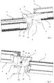
- a window arrangement according to the invention is shown in Figs 1-5 . It includes a first roof window 1, a second roof window 2, a connector bracket 3, and a mounting shoe 4 resting on a load-bearing structure of an inclined roof-structure, here represented by an I-beam 5.
- the window arrangement further includes a flashing assembly generally designated 6.
- the first roof window 1 which is here the uppermost when seen in the direction of inclination of the roof structure, includes a mounting bracket 11, which is connected to the mounting shoe 4 and to a first connecting section 31 the connector bracket 3 in a pivot connection 71, here represented as a bolt extending through aligned openings in the mounting bracket, the mounting shoe, and the first connecting section.
- the second roof window 2 which is here the lowermost when seen in the direction of inclination of the roof structure, includes a mounting bracket 21, which is connected to a second connecting section 32 of the connector bracket 3 in a fixed connection, here represented as two pins 72 extending through aligned openings in the mounting bracket and the second connecting section.
- first roof window 1 may be lowermost and the second roof window 2 uppermost in the mounted state.
- a connector bracket 3 As is seen by comparing Fig. 8 and Fig. 9 the use of a connector bracket 3 according to the invention means that the two roof windows 1, 2 mounted one above the other rotate about the same point of rotation R3, whereas the two windows of the prior art roof window arrangement rotate about different points R1 and R2.
- This difference entails that loads from both roof windows in the roof window arrangement in Fig. 9 can be transferred to one mounting shoe 4 on the load-bearing beam 5, thus potentially allowing a simpler load-bearing structure.
- the connector bracket 3 in Fig. 9 is shown as being convex on the side facing the exterior of the building in the mounted state, whereas the connector brackets in the other figures are concave towards the interior as is presently preferred.
- Opening 311 in the first connecting section 31 is elongate, which allows connector bracket to slide a little bit in relation to the bolt 71, thus allowing the connector bracket to both pivot in relation to the mounting bracket 11 on the first roof window and to accommodate smaller variations during mounting.
- the openings 321 in the second connecting section 32 are circular as they are configured to establish a fixed connection to the mounting bracket 21 on the second roof window.
- first connecting section 31 extends in a first direction D1 from a centre section 30 of the connector bracket 3 and the second connecting section 32 extends in a second direction D2 from the centre section, said first and second directions extending at an angle A in relation to each other.
- the first and second directions D1, D2 are here defined as lines extending through the gravitational centre of the connector bracket and through the gravitational centre of the openings used for establishing the connection to the mounting brackets. If the connector bracket is without such openings and configured for being connected to the mounting brackets of the two roof windows in another way, such as for example by projections adapted for engaging with openings in the mounting brackets, the first and second directions are defined by lines extending through the gravitational centre of the connector bracket and through the centre of the connection with the respective mounting brackets.
- the angle A between the first and second directions is 115 degrees. This angle allows the connector bracket 3 to extend down along the outer side of the frame of the second roof window, and to extend over the beam 5 of the load-bearing structure as is best seen in Figs 2 and 5 , while still having sufficient surface area to possess the necessary strength.
- the rounded shapes of the first and second connecting sections 31, 32 ensures that there are no sharp corners, which might be dangerous to the installers mounting the roof windows, and further facilitates turning of connector bracket in relation to other items during mounting. Moreover, the stresses which tend to build up at sharp corners in a bracket is avoided.
- This embodiment of the connector bracket 3 is plate shaped with the smallest dimension of the plate extending in a third direction D3 extending perpendicular to the first and second directions, i.e. in parallel to the bolt 71 and pins 72, as shown in Fig. 7 .
- the plate shape ensures that the material of connector bracket is concentrated where it is most needed.
- a thicker bracket or a bracket having flanges extending in the third direction or other adaptations intended to increase its torsional strength is, however, within the scope of the invention.
- the second connecting section 32 of the connector bracket 3 is in this embodiment off-set in relation to the centre section 30 and the first connecting section 31 in the third direction D3 extending perpendicular to the first and second directions.
- the oblique section is formed simply by two bends on the plate material used for the connector bracket 3, but the connector bracket could also be formed from two pieces of material, which were interconnected to be arranged at a distance from each other. Likewise, reinforcement could be provided at the bends and/or at the oblique section.
- the connector bracket in Figs 6 and 7 is provided with a third section 33 having openings 331 adapted for interconnection with a supporting element 60 of a flashing assembly 6 as it is shown in Figs 10 and 11 .
- the opening 332 is intended to serve as a point of attachment where a crane or similar handling equipment can get a hold of the connector bracket during mounting, possibly when the connector bracket 3 is already connected to the second window.
- the openings 331 are adapted to align with similar openings 611 in a connecting section 61 of a supporting element 60 so that a fixed connection can be established as described with reference to the connection between the connector bracket 3 and the mounting bracket 21 on the second roof window 2 above.
- the part 62 of the supporting element 60 which is uppermost in Figs 10 and 11 is gutter-shaped and the side flanges 621 defining the gutter are each intended to engage with a bent edge 631 of a flashing member 63 as shown for one of them in Figs 12 and 13 .
- a further flashing member engages with the opposite side flange of the supporting element, but this has been left out to allow the supporting element to be seen.
- the loads from the flashing member 63 covering the space between the first and the second roof window are transmitted at least partially to the connector bracket 3 and from there via the mounting shoe 4 to the load-bearing structure 5, thus minimizing the loads acting on the roof windows 1,2.
- the fact that the supporting element 60 rests on the connector bracket 3 means that the mounting brackets 11, 21 on the roof windows do not have to be configured to carry the supporting element as has been the case in prior art roof window arrangements.
Landscapes
- Engineering & Computer Science (AREA)
- Architecture (AREA)
- Civil Engineering (AREA)
- Structural Engineering (AREA)
- Roof Covering Using Slabs Or Stiff Sheets (AREA)
- Mutual Connection Of Rods And Tubes (AREA)
- Connection Of Plates (AREA)
- Body Structure For Vehicles (AREA)
Abstract
Description
- The present invention relates to a connector bracket for interconnecting roof windows mounted adjacent to each other in an inclined roof structure, one roof window being located below the other roof window when seen in the direction of inclination of the roof structure. The invention further relates to a roof window arrangement for use in an inclined roof structure, and to a method for mounting at least two roof windows in an inclined roof structure, one below the other when seen in the direction of inclination of the roof structure.
- In buildings where it is desired to have a large daylight opening in the roof structure, one or a few roof windows may not suffice and several roof windows can then be mounted in a group, closely side-by-side and/or above each other. The need for achieving a proper attachment of the roof windows to the load-bearing structure of the roof structure, however, necessitate a certain minimum distance between the windows of the group in order to give room for mounting brackets. Moreover, a flashing assembly including cladding, covering and flashing members is needed in order to achieve a proper draining of rain and melt water so that water does not penetrate into the roof structure, and this typically involves drainage gutters between the roof windows.
- Large daylight admitting areas in roof structures can also be achieved by the use of glass panels with comparatively simple frames resembling those used in green houses and where panels are typically overlapping so that water drains off one panel and directly onto the other. Such panel structures, however, typically have considerably poorer insulating properties and load-bearing capacity and it will often not be possible to open the panels as with regular roof windows.
- It is therefore the object of the invention to allow the provision of a roof structure which combines the good insulating and structural properties achieved with groups of roof windows with the simpler structure and comparatively large light admitting area achieved with glass panel structures.
- In a first aspect of the invention this is achieved with a connector bracket comprising a first connecting section configured for being connected to a mounting bracket on a first roof window and a second connecting section configured for being connected to a mounting bracket on a second roof window, where said first connecting section extends in a first direction from a centre section of the connector bracket and is configured for being connected to the mounting bracket on the first roof window in a pivot connection, where said second connecting section extends in a second direction from a centre section of the connector bracket and is configured for being connected to the mounting bracket on the second roof window in a fixed connection, and where said first and second directions are non-parallel.
- This connector bracket is configured for interconnecting roof windows mounted one above the other in an inclined roof structure when seen in the direction of inclination. By allowing the connector bracket to interconnect mounting brackets on the two windows instead of connecting mounting brackets on each roof window separately to the roof structure in a traditional manner, the roof windows can be located closer to each other, thus allowing the light admitting area to be relatively bigger. Moreover, the distance in a direction perpendicular to the plane of the roof structure can be decreased.
- One connecting section being configured for being connected to a mounting bracket in a pivot connection and the other being configured for a fixed connection to a mounting bracket contributes further to allowing the roof windows to be mounted close to each other. The pivot connection allows the connector bracket to swing, either for bringing the second connection section into engagement with the mounting bracket on the second roof window or for swinging the second roof window to which the connector bracket has already been connected into place.
- The fact that the two connecting sections extend in non-parallel directions further contributes to a minimal distance between the windows by allowing one section to extend between the roof windows, while the other extends inwards or outwards along the frame of one of the roof windows, i.e. either towards the interior of the building cover by the roof structure or towards the exterior. It may also allow the section extending between the windows to reach over a beam or a like element of the load-bearing structure of the roof structure of the building. Moreover, the angled shape provides strength and stiffness to the connector bracket and thus to the roof window arrangement made with the connector bracket and thus allows the use of a comparatively smaller connector bracket.
- The side of the connector bracket facing the interior of the building in the mounted state is preferably concave, in other words the angle between the first and second sections on the side of the connector bracket facing the interior of the building in the mounted state is less than 180 degrees.
- If the second leg projects towards the exterior of the building, the side of the connector bracket facing the exterior of the building in the mounted state is preferably concave, in other words the angle between the first and second sections on the side of the connector bracket facing the exterior of the building in the mounted state is less than 180 degrees.
- Using a connector bracket, which is concave towards the interior is presently preferred as it allows an optimal transmission of forces from especially the second roof window to the load-bearing structure. Thus is allows for the use of a relatively small connector bracket, which does not take up much space and which can be produced using a limited amount of material.
- In a preferred embodiment the width of the first and/or second connecting sections in the plane defined by the first and second directions decreases with the distance from the centre section, the first and second sections for example having a tapered and rounded shape so that the overall shape of the connector bracket resembles that of a boomerang.
- It is presently preferred that the first and second directions extend at an angle of 60-150 degrees in relation to each other, but the most expedient angle depends on several factors such as the angle of inclination of the roof structure and the design of the mounting brackets and of the roof structure. An angle of 110-120 degrees is presently considered advantageous for connecting both roof windows to a single load-bearing beam extending in a third direction extending perpendicular to the first and second directions.
- In one embodiment of the connector bracket at least the first and second connecting sections are plate shaped with the smallest dimension of the plate extending in a third direction extending perpendicular to the first and second directions. In this way the connector bracket takes up as little space as possible while still having a high strength in the plane defined by the first and second directions. Roof windows mounted in a group usually do not give rise to high loads in directions perpendicular to the plane defined by the first and second direction, but the connector bracket must of course be able to endure some torsional forces. The necessary thickness will depend on the overall design of the connector bracket and the material chosen and may be determined by simple experiments. It is presently considered advantageous to make the connector bracket from stainless steel.
- In one embodiment, the first connecting section and the second connecting section are off-set in relation to each other in a third direction extending perpendicular to the first and second directions. This allows the two connecting sections to be connected to items, which are not arranged in parallel or to opposite sides of such items as will be described in further detail below. For use in roof window arrangements made with standard roof windows the distance between the first and second connecting sections in the third direction is presently preferred to be 10-100 mm, preferably 20-50 mm.
- The pivot connection between the first connecting section and the mounting bracket on the first roof window may be established in many ways, but simple pin or bolt connections where the pin or bolt define the axis of rotation are presently considered advantageous. In one embodiment the first connecting section therefore includes an opening adapted for receiving a fastening member, such as a pin or bolt. If the opening is elongate it will allow a slack between the fastening member and the connector bracket, which may be advantageous in connection with the mounting process, and which may also compensate for small irregularities and variations.
- The connector bracket may further include a third connecting section adapted for being connected to a supporting element of a flashing assembly. The third connecting section will typically project from the centre section in a fourth direction, which extend substantially in the same plane as the first and section directions. It may include openings, projections and/or the like configured for engagement with the supporting element as will be described in further detail below, but the supporting element may also simply ride on the third connecting section.
- In a second aspect of the invention the object of the invention is achieved with a roof window arrangement for use in an inclined roof structure including at least two roof windows, where one roof window is located below the other roof window when seen in the direction of inclination of the roof structure, and where the two roof windows are interconnected by a connector bracket as described above.
- The roof window arrangement may further include a mounting shoe on the mounting bracket on the first roof window, said mounting shoe being adapted for resting on a load-bearing structure of the roof structure, where the first connecting section of the connector bracket is connected to the shoe in a pivot connection. By connecting the connector bracket to the mounting shoe the loads on the first window may potentially be reduced.
- In one embodiment the mounting shoe is located between the mounting bracket on the first roof window and the first connecting section of the connector bracket. In this way the connection is gravitationally balanced as the loads from the two roof windows act on opposite sides of the mounting shoe.
- The mounting bracket on the first roof window, the mounting shoe, and the first connecting section of the connector bracket can be interconnected by a pin or bolt extending through aligned openings in all three. This makes the connection structurally simple and relatively easy to establish.
- In a third aspect of the invention the object of the invention is achieved with a method for mounting at least two roof windows in an inclined roof structure, one below the other when seen in the direction of inclination of the roof structure, where a first connecting section of a connector bracket is connected to a mounting bracket on a first roof window in a pivot connection and a second connecting section of the connector bracket is connected to a mounting bracket on a second roof window in a fixed connection, said first connecting section extending in a first direction from a centre section of the connector bracket and said second connecting section extending in a second direction from a centre section of the connector bracket, and said first and second directions being non-parallel. As described above with reference to the connector bracket and the roof window arrangement, this provides a structurally simple construction which is optimized with respect to transmitting loads from the roof windows to the load-bearing structure of the roof structure.
- Embodiments and advantages described with reference to one aspect of the invention also applies to the other aspects unless otherwise stated.
- In the following the invention will be described in further detail with reference to non-limiting embodiments shown in the drawing, where:
-
Fig. 1 is a partially cut-away side-view of a roof window arrangement according to the invention, -
Fig. 2 is a partially cut-away cross-sectional view of the roof window arrangement inFig. 1 seen from the opposite side, -
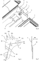
Fig. 3 is a partially cut-away perspective view of the roof window arrangement inFigs 1 and 2 , -
Fig. 4 is another partially cut-away perspective view of the roof window arrangement inFigs 1-3 , where the flashing assembly has been removed, -
Fig. 5 corresponds toFig. 4 but seen from the angle indicated by the arrow V inFig. 4 , -
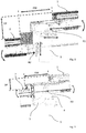
Fig. 6 is a side-view of a connector bracket according to the invention, -
Fig. 7 is an end-view of the connector bracket inFig. 6 , -
Fig. 8 is a partially cut-away cross-sectional view of a prior art roof window arrangement, -
Fig. 9 is a partially cut-away cross-sectional view corresponding toFig. 8 , but showing a roof window arrangement according to the invention, -
Fig. 10 is a perspective view of a connector bracket with a supporting element for a flashing assembly mounted thereon, -
Fig. 11 is a side-view of the connector bracket and supporting element inFig. 10 seen from the direction indicated by the arrow IX inFig. 10 , -
Fig. 12 is a partially cut-away perspective view of the window arrangement corresponding toFig. 3 but including the supporting element shown inFigs 10 and 11 , and -
Fig. 13 is a close-up of the detail marked XIII inFig. 12 with parts of the flashing assembly removed. - A window arrangement according to the invention is shown in
Figs 1-5 . It includes afirst roof window 1, asecond roof window 2, aconnector bracket 3, and amounting shoe 4 resting on a load-bearing structure of an inclined roof-structure, here represented by an I-beam 5. The window arrangement further includes a flashing assembly generally designated 6. - The
first roof window 1, which is here the uppermost when seen in the direction of inclination of the roof structure, includes a mountingbracket 11, which is connected to the mountingshoe 4 and to a first connectingsection 31 theconnector bracket 3 in apivot connection 71, here represented as a bolt extending through aligned openings in the mounting bracket, the mounting shoe, and the first connecting section. - The
second roof window 2, which is here the lowermost when seen in the direction of inclination of the roof structure, includes a mountingbracket 21, which is connected to a second connectingsection 32 of theconnector bracket 3 in a fixed connection, here represented as twopins 72 extending through aligned openings in the mounting bracket and the second connecting section. - In other embodiments the
first roof window 1 may be lowermost and thesecond roof window 2 uppermost in the mounted state. - As is seen by comparing
Fig. 8 and Fig. 9 the use of aconnector bracket 3 according to the invention means that the tworoof windows Fig. 9 can be transferred to one mountingshoe 4 on the load-bearing beam 5, thus potentially allowing a simpler load-bearing structure. Moreover, it means that both the distance DW between the windows in the parallel with the plane of the roof structure, and the distance DP between the exterior sides of the panes of the two roof windows can be decreased. This both saves space, increases the relative light admitting area, and allows a minimalistic visual appearance of the roof window arrangement, which is often preferred in modern architecture. - The
connector bracket 3 inFig. 9 is shown as being convex on the side facing the exterior of the building in the mounted state, whereas the connector brackets in the other figures are concave towards the interior as is presently preferred. - The openings in the
connector bracket 3 used for establishing the connection with the mountingbrackets shoe 4 iare seen clearly inFig 6 , which shows the connector bracket from the same side as inFig. 1 . Opening 311 in the first connectingsection 31 is elongate, which allows connector bracket to slide a little bit in relation to thebolt 71, thus allowing the connector bracket to both pivot in relation to the mountingbracket 11 on the first roof window and to accommodate smaller variations during mounting. Theopenings 321 in the second connectingsection 32, of which only two are used in the embodiment of the roof window arrangement shown, are circular as they are configured to establish a fixed connection to the mountingbracket 21 on the second roof window. - As is also best seen in
Fig. 6 the first connectingsection 31 extends in a first direction D1 from acentre section 30 of theconnector bracket 3 and the second connectingsection 32 extends in a second direction D2 from the centre section, said first and second directions extending at an angle A in relation to each other. - The first and second directions D1, D2 are here defined as lines extending through the gravitational centre of the connector bracket and through the gravitational centre of the openings used for establishing the connection to the mounting brackets. If the connector bracket is without such openings and configured for being connected to the mounting brackets of the two roof windows in another way, such as for example by projections adapted for engaging with openings in the mounting brackets, the first and second directions are defined by lines extending through the gravitational centre of the connector bracket and through the centre of the connection with the respective mounting brackets.
- In the embodiment shown in the drawing, the angle A between the first and second directions is 115 degrees. This angle allows the
connector bracket 3 to extend down along the outer side of the frame of the second roof window, and to extend over thebeam 5 of the load-bearing structure as is best seen inFigs 2 and5 , while still having sufficient surface area to possess the necessary strength. The rounded shapes of the first and second connectingsections - This embodiment of the
connector bracket 3 is plate shaped with the smallest dimension of the plate extending in a third direction D3 extending perpendicular to the first and second directions, i.e. in parallel to thebolt 71 and pins 72, as shown inFig. 7 . This means that the connections between the mountingbrackets connector bracket 3 have a limited extend in the third direction. Moreover, as the loads from theroof windows - As is also seen in
Fig. 7 the second connectingsection 32 of theconnector bracket 3 is in this embodiment off-set in relation to thecentre section 30 and the first connectingsection 31 in the third direction D3 extending perpendicular to the first and second directions. This is achieved by the connector bracket being provided with anoblique section 35. In this embodiment the oblique section is formed simply by two bends on the plate material used for theconnector bracket 3, but the connector bracket could also be formed from two pieces of material, which were interconnected to be arranged at a distance from each other. Likewise, reinforcement could be provided at the bends and/or at the oblique section. - At the top, the connector bracket in
Figs 6 and 7 is provided with athird section 33 havingopenings 331 adapted for interconnection with a supportingelement 60 of a flashingassembly 6 as it is shown inFigs 10 and 11 . Theopening 332 is intended to serve as a point of attachment where a crane or similar handling equipment can get a hold of the connector bracket during mounting, possibly when theconnector bracket 3 is already connected to the second window. - As is seen in
Figs 10 and 11 theopenings 331 are adapted to align withsimilar openings 611 in a connectingsection 61 of a supportingelement 60 so that a fixed connection can be established as described with reference to the connection between theconnector bracket 3 and the mountingbracket 21 on thesecond roof window 2 above. - The
part 62 of the supportingelement 60 which is uppermost inFigs 10 and 11 is gutter-shaped and theside flanges 621 defining the gutter are each intended to engage with abent edge 631 of a flashingmember 63 as shown for one of them inFigs 12 and 13 . In the finished construction a further flashing member engages with the opposite side flange of the supporting element, but this has been left out to allow the supporting element to be seen. In this way the loads from the flashingmember 63 covering the space between the first and the second roof window are transmitted at least partially to theconnector bracket 3 and from there via the mountingshoe 4 to the load-bearing structure 5, thus minimizing the loads acting on theroof windows element 60 rests on theconnector bracket 3 means that the mountingbrackets -
- 1
- First roof window
- 11
- Mounting bracket
- 2
- Second roof window
- 21
- Mounting bracket
- 3
- Connector bracket
- 30
- Centre section
- 31
- First connecting section
- 311
- Opening
- 32
- Second connecting section
- 321
- Opening
- 33
- Third section
- 331
- Openings
- 332
- Openings
- 35
- Oblique section
- 4
- Mounting shoe
- 5
- Load-bearing structure
- 6
- Flashing assembly
- 60
- Supporting element
- 61
- Connecting section
- 611
- Openings
- 62
- Part of the supporting element
- 63
- Flashing member
- 631
- Bent edge
- 71
- Pivot connection
- 72
- Pins
- A
- Angle
- D1
- First direction
- D2
- Second direction
- D3
- Third direction
- DW
- Distance between windows
- DP
- Distance between the exterior sides of the panes
- R1
- Point of rotation
- R2
- Point of rotation
- R3
- Point of rotation
Claims (13)
- A connector bracket (3) for interconnecting roof windows (1,2) mounted adjacent to each other in an inclined roof structure, one roof window being located below the other roof window when seen in the direction of inclination of the roof structure, characterized in that
said connector bracket (3) comprises a first connecting section (31) configured for being connected to a mounting bracket (11) on a first roof window (1) and a second connecting section (32) configured for being connected to a mounting bracket (31) on a second roof window (2),
said first connecting section (31) extends in a first direction (D1) from a centre section (30) of the connector bracket and is configured for being connected to the mounting bracket on the first roof window in a pivot connection (71),
said second connecting section (32) extends in a second direction (D2) from a centre section (30) of the connector bracket and is configured for being connected to the mounting bracket (21) on the second roof window in a fixed connection (72), and
said first and second directions (D1, D2) are non-parallel. - A connector bracket according to claim 1, where said first and second directions (D1, D2) extend at an angle (A) of 60-150 degrees in relation to each other.
- A connector bracket according to claim 2, where said first and second directions (D1, D2) extend at an angle (A) of 110-120 degrees in relation to each other.
- A connector bracket according to one or more of claims 1-3, where at least the first and second connecting sections (31, 32) are plate shaped with the smallest dimension of the plate extending in a third direction (D3) extending perpendicular to the first and second directions.
- A connector bracket according to one or more of claims 1-4, the first connecting section (31) and the second connecting section (32) are off-set in relation to each other in a third direction (D3) extending perpendicular to the first and second directions (D1, D2).
- A connector bracket according to claim 5, the distance between the first and second connecting sections (31, 32) in the third direction (D3) is 10-100 mm, preferably 20-50 mm.
- A connector bracket according to one or more of claims 1-6, the first connecting section (31) includes an opening (311) adapted for receiving a fastening member (71), such as a pin or bolt, said opening preferably being elongate.
- A connector bracket according to one or more of claims 1-7, further including a third connecting section (33) adapted for being connected to a supporting element (60) of a flashing assembly (6).
- A roof window arrangement for use in an inclined roof structure including at least two roof windows (1, 2), where one roof window is located below the other roof window when seen in the direction of inclination of the roof structure, and where the two roof windows are interconnected by a connector bracket (3) according to one or more of claims 1-8.
- A roof window arrangement according to claim 9, further including a mounting shoe (4) on the mounting bracket (11) on the first roof window (1), said mounting shoe being adapted for resting on a load-bearing structure (5) of the roof structure, and where the first connecting section (31) of the connector bracket (3) is connected to the mounting shoe (4) in a pivot connection (71).
- A roof window arrangement according to claim 10, where the mounting shoe (4) is located between the mounting bracket (11) on the first roof window (1) and the first connecting section (31) of the connector bracket (3).
- A roof window arrangement according to claim 10 or 11, where the mounting bracket (11) on the first roof window (1), the mounting shoe (4), and the first connecting section (31) of the connector bracket (3) are interconnected by a pin or bolt (71) extending through aligned openings therein.
- A method for mounting at least two roof windows (1, 2) in an inclined roof structure, one below the other when seen in the direction of inclination of the roof structure, where a first connecting section (31) of a connector bracket (3) is connected to a mounting bracket (11) on a first roof window (1) in a pivot connection and a second connecting section (32) of the connector bracket is connected to a mounting bracket (21) on a second roof window (2) in a fixed connection, said first connecting section extending in a first direction (D1) from a centre section (30) of the connector bracket and said second connecting section extending in a second direction (D2) from a centre section of the connector bracket, and said first and second directions being non-parallel.
Priority Applications (1)
| Application Number | Priority Date | Filing Date | Title |
|---|---|---|---|
| PL20150910T PL3680415T3 (en) | 2019-01-10 | 2020-01-09 | A roof window arrangement and a method for mounting at least two roof windows in an inclined roof structure |
Applications Claiming Priority (1)
| Application Number | Priority Date | Filing Date | Title |
|---|---|---|---|
| DKPA201970013 | 2019-01-10 |
Publications (2)
| Publication Number | Publication Date |
|---|---|
| EP3680415A1 true EP3680415A1 (en) | 2020-07-15 |
| EP3680415B1 EP3680415B1 (en) | 2021-09-22 |
Family
ID=69156307
Family Applications (1)
| Application Number | Title | Priority Date | Filing Date |
|---|---|---|---|
| EP20150910.6A Active EP3680415B1 (en) | 2019-01-10 | 2020-01-09 | A roof window arrangement and a method for mounting at least two roof windows in an inclined roof structure |
Country Status (5)
| Country | Link |
|---|---|
| US (1) | US11255090B2 (en) |
| EP (1) | EP3680415B1 (en) |
| CN (1) | CN212427834U (en) |
| DK (1) | DK3680415T3 (en) |
| PL (1) | PL3680415T3 (en) |
Cited By (2)
| Publication number | Priority date | Publication date | Assignee | Title |
|---|---|---|---|---|
| USD1052757S1 (en) | 2023-03-30 | 2024-11-26 | Vkr Holding A/S | Window |
| USD1065597S1 (en) | 2023-03-30 | 2025-03-04 | Vkr Holding A/S | Window component |
Families Citing this family (1)
| Publication number | Priority date | Publication date | Assignee | Title |
|---|---|---|---|---|
| US12139914B2 (en) * | 2020-08-26 | 2024-11-12 | Vkr Holding A/S | Connector arrangement and a method for weather proofing a roof window arrangement |
Citations (3)
| Publication number | Priority date | Publication date | Assignee | Title |
|---|---|---|---|---|
| US20140366468A1 (en) * | 2010-12-29 | 2014-12-18 | Vkr Holdings A/S | Window system having flexible means for mounting |
| WO2015028030A1 (en) * | 2013-08-30 | 2015-03-05 | Vkr Holding A/S | A connector element for use in a flashing assembly for roof windows mounted side-by-side and a method for mounting a flashing assembly |
| EP3252256A1 (en) * | 2016-05-31 | 2017-12-06 | VKR Holding A/S | Window bracket assembly |
Family Cites Families (38)
| Publication number | Priority date | Publication date | Assignee | Title |
|---|---|---|---|---|
| US2056444A (en) * | 1934-11-16 | 1936-10-06 | Briggen Hans | Roof glazing structure |
| US2565200A (en) * | 1946-06-19 | 1951-08-21 | Lawrence O Burress | Window |
| US3001331A (en) * | 1959-06-19 | 1961-09-26 | Pendennis Company Ltd | Thermal covering for roofs |
| DE2146029B1 (en) * | 1971-09-15 | 1973-05-17 | ROOF CONSTRUCTION FOR HALLS, STADIUM OR. DGL | |
| US3771277A (en) * | 1972-06-06 | 1973-11-13 | R J Ind Inc | Building and method of constructing same from interconnected panels |
| US4296733A (en) * | 1976-08-05 | 1981-10-27 | Saunders Norman B | Heating, lighting and ventilation systems |
| DE7829553U1 (en) | 1978-10-04 | 1979-01-18 | Stiebel Eltron Gmbh & Co Kg, 3450 Holzminden | MOUNTING FRAME FOR SOLAR COLLECTORS |
| DE7920893U1 (en) | 1979-07-21 | 1986-11-13 | Blefa GmbH, 5910 Kreuztal | Covering collar for roof windows, solar panels or other roof fittings located in the roof area |
| US4327532A (en) * | 1980-07-18 | 1982-05-04 | Kawneer Company, Inc. | Adjustable angle eave apparatus |
| US4426812A (en) * | 1981-06-25 | 1984-01-24 | Argyle Management Company | Interior covering material for a greenhouse |
| DE3206871C1 (en) | 1982-02-26 | 1983-06-01 | Velux GmbH - Bauzubehör, 2000 Hamburg | Combination roofing frame for roof windows to be installed next to each other |
| FR2654133A1 (en) | 1989-11-03 | 1991-05-10 | Safiza | LIGHTING AND / OR VENTILATION ASSEMBLY OF A COVERED ROOM COMPRISING A ROOF WINDOW ASSOCIATED WITH A PARTITION WINDOW. |
| DE20206327U1 (en) | 2002-04-22 | 2002-07-18 | Vkr Holding A/S, Soeborg | Device for shielding windows installed in an extension to one another |
| AU2003275944A1 (en) | 2002-12-16 | 2004-07-09 | Vkr Holding A/S | Side flashing member and a method of making it |
| CN2701951Y (en) | 2003-11-21 | 2005-05-25 | Vkr控股公司 | Cover plate sealing member for inclined lucarne |
| US8025267B2 (en) | 2004-05-24 | 2011-09-27 | Srb Construction Technologies Pty. Ltd. | Concrete sideform system |
| CA2635220A1 (en) * | 2005-12-29 | 2007-07-05 | Sunpower Corporation, Systems | One piece, collapsible pv assembly |
| US7798461B2 (en) * | 2006-06-19 | 2010-09-21 | Hackney Michael P | Rotating bracket assembly for collapsible and permanent building-frame construction |
| US8061091B2 (en) * | 2008-06-27 | 2011-11-22 | Sunpower Corporation | Photovoltaic module kit including connector assembly for non-penetrating array installation |
| US20100089390A1 (en) * | 2008-10-13 | 2010-04-15 | Sunlink, Corp | Solar array mounting system |
| DE202009001098U1 (en) | 2009-01-27 | 2009-04-30 | Mounting Systems Gmbh | Solar module mounting |
| US7658356B1 (en) | 2009-01-29 | 2010-02-09 | Unistrut International Corporation | Mounting bracket for solar panel applications |
| US9134044B2 (en) | 2010-01-25 | 2015-09-15 | Vermont Slate & Copper Services, Inc. | Roof mount assembly |
| DE102010029002A1 (en) * | 2010-05-17 | 2011-11-17 | Hilti Aktiengesellschaft | Mounting foot for solar modules and mounting system with several such mounting feet |
| AU2011295657A1 (en) * | 2010-09-03 | 2013-03-14 | Dynoraxx, Inc. | Solar panel racking assembly |
| DK2472027T3 (en) | 2010-12-29 | 2017-05-22 | Vkr Holding As | PROCEDURE FOR DETERMINING A COVERAGE ON A SKYLIGHT WINDOW |
| EP2472025B1 (en) | 2010-12-29 | 2014-02-26 | VKR Holding A/S | A flashing member with a compensation member and a kit including such a flashing member |
| EP2472028B1 (en) * | 2010-12-29 | 2017-12-13 | VKR Holding A/S | A method of installing a window arrangement comprising a number of neighbouring windows, and such a window arrangement |
| PL2472043T3 (en) | 2010-12-29 | 2015-08-31 | Vkr Holding As | A window system having a concealed operator |
| EP2653631B1 (en) * | 2010-12-29 | 2017-06-28 | VKR Holding A/S | A window system having a frame structure and a bracket arrangement |
| DE202012006688U1 (en) | 2012-07-10 | 2013-10-14 | Vkr Holding A/S | Roof window with cover means for a frame |
| US9263985B2 (en) * | 2012-11-13 | 2016-02-16 | Pi Solar Technology Gmbh | Rooftop photovoltaic modules |
| DK177601B1 (en) | 2013-01-07 | 2013-11-18 | Vkr Holding As | A gutter-like flashing member and a roof structure including such a flashing member |
| DE102013109391A1 (en) * | 2013-08-29 | 2015-03-19 | Jürgen Grimmeisen | lamella roof |
| DK178009B1 (en) | 2013-08-30 | 2015-03-02 | Vkr Holding As | A window system adapted for being mounted in an inclined surface of a building and a method for draining condensation from such a window system |
| US9540818B2 (en) | 2014-03-24 | 2017-01-10 | Bluescope Buildings North America, Inc. | Roof ridge integrated water-shedding apparatus |
| PL3282064T3 (en) | 2016-08-03 | 2019-07-31 | Vkr Holding A/S | A connector set for use in a flashing assembly for roof windows mounted side-by-side |
| DK179266B1 (en) | 2016-08-03 | 2018-03-19 | Vkr Holding As | A connector element for use in a flashing assembly for roof windows mounted side-by-side and a connector set including such a connector element |
-
2020
- 2020-01-08 US US16/737,820 patent/US11255090B2/en active Active
- 2020-01-09 PL PL20150910T patent/PL3680415T3/en unknown
- 2020-01-09 EP EP20150910.6A patent/EP3680415B1/en active Active
- 2020-01-09 DK DK20150910.6T patent/DK3680415T3/en active
- 2020-01-10 CN CN202020057436.5U patent/CN212427834U/en active Active
Patent Citations (3)
| Publication number | Priority date | Publication date | Assignee | Title |
|---|---|---|---|---|
| US20140366468A1 (en) * | 2010-12-29 | 2014-12-18 | Vkr Holdings A/S | Window system having flexible means for mounting |
| WO2015028030A1 (en) * | 2013-08-30 | 2015-03-05 | Vkr Holding A/S | A connector element for use in a flashing assembly for roof windows mounted side-by-side and a method for mounting a flashing assembly |
| EP3252256A1 (en) * | 2016-05-31 | 2017-12-06 | VKR Holding A/S | Window bracket assembly |
Cited By (2)
| Publication number | Priority date | Publication date | Assignee | Title |
|---|---|---|---|---|
| USD1052757S1 (en) | 2023-03-30 | 2024-11-26 | Vkr Holding A/S | Window |
| USD1065597S1 (en) | 2023-03-30 | 2025-03-04 | Vkr Holding A/S | Window component |
Also Published As
| Publication number | Publication date |
|---|---|
| US20200224420A1 (en) | 2020-07-16 |
| US11255090B2 (en) | 2022-02-22 |
| EP3680415B1 (en) | 2021-09-22 |
| PL3680415T3 (en) | 2022-01-31 |
| CN212427834U (en) | 2021-01-29 |
| DK3680415T3 (en) | 2021-11-08 |
Similar Documents
| Publication | Publication Date | Title |
|---|---|---|
| EP3680415B1 (en) | A roof window arrangement and a method for mounting at least two roof windows in an inclined roof structure | |
| IE64975B1 (en) | Conservatories | |
| AU720746B2 (en) | Building structure | |
| US4283900A (en) | Corner brace for building construction | |
| NO318344B1 (en) | Mounting and hinge fittings for a panel and panel system comprising such a bracket | |
| JP2020159129A (en) | Roof structure | |
| KR102779683B1 (en) | Safety barrier for modular | |
| GB2378478A (en) | Tiltable shoe for mounting a glazing bar | |
| CN215330420U (en) | Roof structure, roof and wall stand column connecting structure, house framework and house | |
| JP3759500B2 (en) | Building wall | |
| AU2019420431B2 (en) | Roof frame structure | |
| CN210597805U (en) | Slope roof installation structure | |
| JP2019112904A (en) | Building construction method | |
| EP3839167A1 (en) | Method for installing a pitched roof | |
| CN212534696U (en) | Distortion sunshade curtain system | |
| CN215955459U (en) | An outdoor antenna reinforcement assembly | |
| CN217840834U (en) | Steel construction external scaffolding is wall structure and external scaffolding even | |
| JP3652344B2 (en) | Building wall | |
| EP1067251A2 (en) | Support Bracket | |
| WO1999046456A1 (en) | Portals | |
| JPH08109753A (en) | Snowbreaker in an assembly building | |
| JP7282569B2 (en) | Building construction method | |
| JPH0338378B2 (en) | ||
| JP2552776B2 (en) | Roof of unit house | |
| GB2378455A (en) | Framework connectors |
Legal Events
| Date | Code | Title | Description |
|---|---|---|---|
| PUAI | Public reference made under article 153(3) epc to a published international application that has entered the european phase |
Free format text: ORIGINAL CODE: 0009012 |
|
| STAA | Information on the status of an ep patent application or granted ep patent |
Free format text: STATUS: THE APPLICATION HAS BEEN PUBLISHED |
|
| AK | Designated contracting states |
Kind code of ref document: A1 Designated state(s): AL AT BE BG CH CY CZ DE DK EE ES FI FR GB GR HR HU IE IS IT LI LT LU LV MC MK MT NL NO PL PT RO RS SE SI SK SM TR |
|
| AX | Request for extension of the european patent |
Extension state: BA ME |
|
| STAA | Information on the status of an ep patent application or granted ep patent |
Free format text: STATUS: REQUEST FOR EXAMINATION WAS MADE |
|
| 17P | Request for examination filed |
Effective date: 20210113 |
|
| RBV | Designated contracting states (corrected) |
Designated state(s): AL AT BE BG CH CY CZ DE DK EE ES FI FR GB GR HR HU IE IS IT LI LT LU LV MC MK MT NL NO PL PT RO RS SE SI SK SM TR |
|
| GRAP | Despatch of communication of intention to grant a patent |
Free format text: ORIGINAL CODE: EPIDOSNIGR1 |
|
| STAA | Information on the status of an ep patent application or granted ep patent |
Free format text: STATUS: GRANT OF PATENT IS INTENDED |
|
| INTG | Intention to grant announced |
Effective date: 20210517 |
|
| GRAS | Grant fee paid |
Free format text: ORIGINAL CODE: EPIDOSNIGR3 |
|
| GRAA | (expected) grant |
Free format text: ORIGINAL CODE: 0009210 |
|
| STAA | Information on the status of an ep patent application or granted ep patent |
Free format text: STATUS: THE PATENT HAS BEEN GRANTED |
|
| AK | Designated contracting states |
Kind code of ref document: B1 Designated state(s): AL AT BE BG CH CY CZ DE DK EE ES FI FR GB GR HR HU IE IS IT LI LT LU LV MC MK MT NL NO PL PT RO RS SE SI SK SM TR |
|
| REG | Reference to a national code |
Ref country code: GB Ref legal event code: FG4D |
|
| REG | Reference to a national code |
Ref country code: IE Ref legal event code: FG4D |
|
| REG | Reference to a national code |
Ref country code: DE Ref legal event code: R096 Ref document number: 602020000557 Country of ref document: DE |
|
| REG | Reference to a national code |
Ref country code: CH Ref legal event code: EP Ref country code: AT Ref legal event code: REF Ref document number: 1432442 Country of ref document: AT Kind code of ref document: T Effective date: 20211015 |
|
| REG | Reference to a national code |
Ref country code: DK Ref legal event code: T3 Effective date: 20211101 |
|
| REG | Reference to a national code |
Ref country code: SE Ref legal event code: TRGR |
|
| REG | Reference to a national code |
Ref country code: NL Ref legal event code: FP |
|
| REG | Reference to a national code |
Ref country code: LT Ref legal event code: MG9D |
|
| PG25 | Lapsed in a contracting state [announced via postgrant information from national office to epo] |
Ref country code: RS Free format text: LAPSE BECAUSE OF FAILURE TO SUBMIT A TRANSLATION OF THE DESCRIPTION OR TO PAY THE FEE WITHIN THE PRESCRIBED TIME-LIMIT Effective date: 20210922 Ref country code: FI Free format text: LAPSE BECAUSE OF FAILURE TO SUBMIT A TRANSLATION OF THE DESCRIPTION OR TO PAY THE FEE WITHIN THE PRESCRIBED TIME-LIMIT Effective date: 20210922 Ref country code: HR Free format text: LAPSE BECAUSE OF FAILURE TO SUBMIT A TRANSLATION OF THE DESCRIPTION OR TO PAY THE FEE WITHIN THE PRESCRIBED TIME-LIMIT Effective date: 20210922 Ref country code: NO Free format text: LAPSE BECAUSE OF FAILURE TO SUBMIT A TRANSLATION OF THE DESCRIPTION OR TO PAY THE FEE WITHIN THE PRESCRIBED TIME-LIMIT Effective date: 20211222 Ref country code: BG Free format text: LAPSE BECAUSE OF FAILURE TO SUBMIT A TRANSLATION OF THE DESCRIPTION OR TO PAY THE FEE WITHIN THE PRESCRIBED TIME-LIMIT Effective date: 20211222 Ref country code: LT Free format text: LAPSE BECAUSE OF FAILURE TO SUBMIT A TRANSLATION OF THE DESCRIPTION OR TO PAY THE FEE WITHIN THE PRESCRIBED TIME-LIMIT Effective date: 20210922 |
|
| PG25 | Lapsed in a contracting state [announced via postgrant information from national office to epo] |
Ref country code: LV Free format text: LAPSE BECAUSE OF FAILURE TO SUBMIT A TRANSLATION OF THE DESCRIPTION OR TO PAY THE FEE WITHIN THE PRESCRIBED TIME-LIMIT Effective date: 20210922 Ref country code: GR Free format text: LAPSE BECAUSE OF FAILURE TO SUBMIT A TRANSLATION OF THE DESCRIPTION OR TO PAY THE FEE WITHIN THE PRESCRIBED TIME-LIMIT Effective date: 20211223 |
|
| PG25 | Lapsed in a contracting state [announced via postgrant information from national office to epo] |
Ref country code: IS Free format text: LAPSE BECAUSE OF FAILURE TO SUBMIT A TRANSLATION OF THE DESCRIPTION OR TO PAY THE FEE WITHIN THE PRESCRIBED TIME-LIMIT Effective date: 20220122 Ref country code: SK Free format text: LAPSE BECAUSE OF FAILURE TO SUBMIT A TRANSLATION OF THE DESCRIPTION OR TO PAY THE FEE WITHIN THE PRESCRIBED TIME-LIMIT Effective date: 20210922 Ref country code: RO Free format text: LAPSE BECAUSE OF FAILURE TO SUBMIT A TRANSLATION OF THE DESCRIPTION OR TO PAY THE FEE WITHIN THE PRESCRIBED TIME-LIMIT Effective date: 20210922 Ref country code: PT Free format text: LAPSE BECAUSE OF FAILURE TO SUBMIT A TRANSLATION OF THE DESCRIPTION OR TO PAY THE FEE WITHIN THE PRESCRIBED TIME-LIMIT Effective date: 20220124 Ref country code: ES Free format text: LAPSE BECAUSE OF FAILURE TO SUBMIT A TRANSLATION OF THE DESCRIPTION OR TO PAY THE FEE WITHIN THE PRESCRIBED TIME-LIMIT Effective date: 20210922 Ref country code: EE Free format text: LAPSE BECAUSE OF FAILURE TO SUBMIT A TRANSLATION OF THE DESCRIPTION OR TO PAY THE FEE WITHIN THE PRESCRIBED TIME-LIMIT Effective date: 20210922 Ref country code: CZ Free format text: LAPSE BECAUSE OF FAILURE TO SUBMIT A TRANSLATION OF THE DESCRIPTION OR TO PAY THE FEE WITHIN THE PRESCRIBED TIME-LIMIT Effective date: 20210922 Ref country code: AL Free format text: LAPSE BECAUSE OF FAILURE TO SUBMIT A TRANSLATION OF THE DESCRIPTION OR TO PAY THE FEE WITHIN THE PRESCRIBED TIME-LIMIT Effective date: 20210922 |
|
| REG | Reference to a national code |
Ref country code: DE Ref legal event code: R097 Ref document number: 602020000557 Country of ref document: DE |
|
| PLBE | No opposition filed within time limit |
Free format text: ORIGINAL CODE: 0009261 |
|
| STAA | Information on the status of an ep patent application or granted ep patent |
Free format text: STATUS: NO OPPOSITION FILED WITHIN TIME LIMIT |
|
| 26N | No opposition filed |
Effective date: 20220623 |
|
| PG25 | Lapsed in a contracting state [announced via postgrant information from national office to epo] |
Ref country code: MC Free format text: LAPSE BECAUSE OF FAILURE TO SUBMIT A TRANSLATION OF THE DESCRIPTION OR TO PAY THE FEE WITHIN THE PRESCRIBED TIME-LIMIT Effective date: 20210922 |
|
| PG25 | Lapsed in a contracting state [announced via postgrant information from national office to epo] |
Ref country code: LU Free format text: LAPSE BECAUSE OF NON-PAYMENT OF DUE FEES Effective date: 20220109 |
|
| PG25 | Lapsed in a contracting state [announced via postgrant information from national office to epo] |
Ref country code: SI Free format text: LAPSE BECAUSE OF FAILURE TO SUBMIT A TRANSLATION OF THE DESCRIPTION OR TO PAY THE FEE WITHIN THE PRESCRIBED TIME-LIMIT Effective date: 20210922 |
|
| REG | Reference to a national code |
Ref country code: AT Ref legal event code: UEP Ref document number: 1432442 Country of ref document: AT Kind code of ref document: T Effective date: 20210922 |
|
| PG25 | Lapsed in a contracting state [announced via postgrant information from national office to epo] |
Ref country code: IE Free format text: LAPSE BECAUSE OF NON-PAYMENT OF DUE FEES Effective date: 20220109 |
|
| PG25 | Lapsed in a contracting state [announced via postgrant information from national office to epo] |
Ref country code: SM Free format text: LAPSE BECAUSE OF FAILURE TO SUBMIT A TRANSLATION OF THE DESCRIPTION OR TO PAY THE FEE WITHIN THE PRESCRIBED TIME-LIMIT Effective date: 20210922 Ref country code: MK Free format text: LAPSE BECAUSE OF FAILURE TO SUBMIT A TRANSLATION OF THE DESCRIPTION OR TO PAY THE FEE WITHIN THE PRESCRIBED TIME-LIMIT Effective date: 20210922 Ref country code: CY Free format text: LAPSE BECAUSE OF FAILURE TO SUBMIT A TRANSLATION OF THE DESCRIPTION OR TO PAY THE FEE WITHIN THE PRESCRIBED TIME-LIMIT Effective date: 20210922 |
|
| PG25 | Lapsed in a contracting state [announced via postgrant information from national office to epo] |
Ref country code: HU Free format text: LAPSE BECAUSE OF FAILURE TO SUBMIT A TRANSLATION OF THE DESCRIPTION OR TO PAY THE FEE WITHIN THE PRESCRIBED TIME-LIMIT; INVALID AB INITIO Effective date: 20200109 |
|
| PG25 | Lapsed in a contracting state [announced via postgrant information from national office to epo] |
Ref country code: MT Free format text: LAPSE BECAUSE OF FAILURE TO SUBMIT A TRANSLATION OF THE DESCRIPTION OR TO PAY THE FEE WITHIN THE PRESCRIBED TIME-LIMIT Effective date: 20210922 |
|
| PG25 | Lapsed in a contracting state [announced via postgrant information from national office to epo] |
Ref country code: TR Free format text: LAPSE BECAUSE OF FAILURE TO SUBMIT A TRANSLATION OF THE DESCRIPTION OR TO PAY THE FEE WITHIN THE PRESCRIBED TIME-LIMIT Effective date: 20210922 |
|
| PGFP | Annual fee paid to national office [announced via postgrant information from national office to epo] |
Ref country code: GB Payment date: 20251204 Year of fee payment: 7 |
|
| PGFP | Annual fee paid to national office [announced via postgrant information from national office to epo] |
Ref country code: FR Payment date: 20251222 Year of fee payment: 7 Ref country code: NL Payment date: 20251215 Year of fee payment: 7 |
|
| PGFP | Annual fee paid to national office [announced via postgrant information from national office to epo] |
Ref country code: SE Payment date: 20251210 Year of fee payment: 7 |
|
| PGFP | Annual fee paid to national office [announced via postgrant information from national office to epo] |
Ref country code: PL Payment date: 20251212 Year of fee payment: 7 |
|
| REG | Reference to a national code |
Ref country code: CH Ref legal event code: U11 Free format text: ST27 STATUS EVENT CODE: U-0-0-U10-U11 (AS PROVIDED BY THE NATIONAL OFFICE) Effective date: 20260201 |
|
| PGFP | Annual fee paid to national office [announced via postgrant information from national office to epo] |
Ref country code: DK Payment date: 20260113 Year of fee payment: 7 Ref country code: DE Payment date: 20251203 Year of fee payment: 7 |
|
| PGFP | Annual fee paid to national office [announced via postgrant information from national office to epo] |
Ref country code: AT Payment date: 20251230 Year of fee payment: 7 |
|
| PGFP | Annual fee paid to national office [announced via postgrant information from national office to epo] |
Ref country code: BE Payment date: 20260106 Year of fee payment: 7 Ref country code: IT Payment date: 20251219 Year of fee payment: 7 |
|
| PGFP | Annual fee paid to national office [announced via postgrant information from national office to epo] |
Ref country code: CH Payment date: 20260201 Year of fee payment: 7 |