EP3680394A1 - Shovel - Google Patents
Shovel Download PDFInfo
- Publication number
- EP3680394A1 EP3680394A1 EP18854981.0A EP18854981A EP3680394A1 EP 3680394 A1 EP3680394 A1 EP 3680394A1 EP 18854981 A EP18854981 A EP 18854981A EP 3680394 A1 EP3680394 A1 EP 3680394A1
- Authority
- EP
- European Patent Office
- Prior art keywords
- turning
- shovel
- teaching
- bucket
- turning body
- Prior art date
- Legal status (The legal status is an assumption and is not a legal conclusion. Google has not performed a legal analysis and makes no representation as to the accuracy of the status listed.)
- Granted
Links
Images




Classifications
-
- E—FIXED CONSTRUCTIONS
- E02—HYDRAULIC ENGINEERING; FOUNDATIONS; SOIL SHIFTING
- E02F—DREDGING; SOIL-SHIFTING
- E02F3/00—Dredgers; Soil-shifting machines
- E02F3/04—Dredgers; Soil-shifting machines mechanically-driven
- E02F3/28—Dredgers; Soil-shifting machines mechanically-driven with digging tools mounted on a dipper- or bucket-arm, i.e. there is either one arm or a pair of arms, e.g. dippers, buckets
- E02F3/36—Component parts
- E02F3/42—Drives for dippers, buckets, dipper-arms or bucket-arms
- E02F3/43—Control of dipper or bucket position; Control of sequence of drive operations
- E02F3/435—Control of dipper or bucket position; Control of sequence of drive operations for dipper-arms, backhoes or the like
- E02F3/439—Automatic repositioning of the implement, e.g. automatic dumping, auto-return
-
- E—FIXED CONSTRUCTIONS
- E02—HYDRAULIC ENGINEERING; FOUNDATIONS; SOIL SHIFTING
- E02F—DREDGING; SOIL-SHIFTING
- E02F9/00—Component parts of dredgers or soil-shifting machines, not restricted to one of the kinds covered by groups E02F3/00 - E02F7/00
- E02F9/20—Drives; Control devices
- E02F9/2025—Particular purposes of control systems not otherwise provided for
- E02F9/2037—Coordinating the movements of the implement and of the frame
-
- E—FIXED CONSTRUCTIONS
- E02—HYDRAULIC ENGINEERING; FOUNDATIONS; SOIL SHIFTING
- E02F—DREDGING; SOIL-SHIFTING
- E02F3/00—Dredgers; Soil-shifting machines
- E02F3/04—Dredgers; Soil-shifting machines mechanically-driven
- E02F3/28—Dredgers; Soil-shifting machines mechanically-driven with digging tools mounted on a dipper- or bucket-arm, i.e. there is either one arm or a pair of arms, e.g. dippers, buckets
- E02F3/36—Component parts
- E02F3/42—Drives for dippers, buckets, dipper-arms or bucket-arms
- E02F3/43—Control of dipper or bucket position; Control of sequence of drive operations
- E02F3/435—Control of dipper or bucket position; Control of sequence of drive operations for dipper-arms, backhoes or the like
-
- E—FIXED CONSTRUCTIONS
- E02—HYDRAULIC ENGINEERING; FOUNDATIONS; SOIL SHIFTING
- E02F—DREDGING; SOIL-SHIFTING
- E02F3/00—Dredgers; Soil-shifting machines
- E02F3/04—Dredgers; Soil-shifting machines mechanically-driven
- E02F3/28—Dredgers; Soil-shifting machines mechanically-driven with digging tools mounted on a dipper- or bucket-arm, i.e. there is either one arm or a pair of arms, e.g. dippers, buckets
- E02F3/30—Dredgers; Soil-shifting machines mechanically-driven with digging tools mounted on a dipper- or bucket-arm, i.e. there is either one arm or a pair of arms, e.g. dippers, buckets with a dipper-arm pivoted on a cantilever beam, i.e. boom
- E02F3/32—Dredgers; Soil-shifting machines mechanically-driven with digging tools mounted on a dipper- or bucket-arm, i.e. there is either one arm or a pair of arms, e.g. dippers, buckets with a dipper-arm pivoted on a cantilever beam, i.e. boom working downwardly and towards the machine, e.g. with backhoes
-
- E—FIXED CONSTRUCTIONS
- E02—HYDRAULIC ENGINEERING; FOUNDATIONS; SOIL SHIFTING
- E02F—DREDGING; SOIL-SHIFTING
- E02F3/00—Dredgers; Soil-shifting machines
- E02F3/04—Dredgers; Soil-shifting machines mechanically-driven
- E02F3/28—Dredgers; Soil-shifting machines mechanically-driven with digging tools mounted on a dipper- or bucket-arm, i.e. there is either one arm or a pair of arms, e.g. dippers, buckets
- E02F3/36—Component parts
- E02F3/42—Drives for dippers, buckets, dipper-arms or bucket-arms
- E02F3/43—Control of dipper or bucket position; Control of sequence of drive operations
- E02F3/435—Control of dipper or bucket position; Control of sequence of drive operations for dipper-arms, backhoes or the like
- E02F3/437—Control of dipper or bucket position; Control of sequence of drive operations for dipper-arms, backhoes or the like providing automatic sequences of movements, e.g. linear excavation, keeping dipper angle constant
-
- E—FIXED CONSTRUCTIONS
- E02—HYDRAULIC ENGINEERING; FOUNDATIONS; SOIL SHIFTING
- E02F—DREDGING; SOIL-SHIFTING
- E02F9/00—Component parts of dredgers or soil-shifting machines, not restricted to one of the kinds covered by groups E02F3/00 - E02F7/00
- E02F9/08—Superstructures; Supports for superstructures
- E02F9/10—Supports for movable superstructures mounted on travelling or walking gears or on other superstructures
- E02F9/12—Slewing or traversing gears
- E02F9/121—Turntables, i.e. structure rotatable about 360°
- E02F9/123—Drives or control devices specially adapted therefor
-
- E—FIXED CONSTRUCTIONS
- E02—HYDRAULIC ENGINEERING; FOUNDATIONS; SOIL SHIFTING
- E02F—DREDGING; SOIL-SHIFTING
- E02F9/00—Component parts of dredgers or soil-shifting machines, not restricted to one of the kinds covered by groups E02F3/00 - E02F7/00
- E02F9/20—Drives; Control devices
- E02F9/2004—Control mechanisms, e.g. control levers
-
- E—FIXED CONSTRUCTIONS
- E02—HYDRAULIC ENGINEERING; FOUNDATIONS; SOIL SHIFTING
- E02F—DREDGING; SOIL-SHIFTING
- E02F9/00—Component parts of dredgers or soil-shifting machines, not restricted to one of the kinds covered by groups E02F3/00 - E02F7/00
- E02F9/20—Drives; Control devices
- E02F9/2025—Particular purposes of control systems not otherwise provided for
- E02F9/2041—Automatic repositioning of implements, i.e. memorising determined positions of the implement
-
- E—FIXED CONSTRUCTIONS
- E02—HYDRAULIC ENGINEERING; FOUNDATIONS; SOIL SHIFTING
- E02F—DREDGING; SOIL-SHIFTING
- E02F9/00—Component parts of dredgers or soil-shifting machines, not restricted to one of the kinds covered by groups E02F3/00 - E02F7/00
- E02F9/26—Indicating devices
- E02F9/264—Sensors and their calibration for indicating the position of the work tool
- E02F9/265—Sensors and their calibration for indicating the position of the work tool with follow-up actions (e.g. control signals sent to actuate the work tool)
-
- G—PHYSICS
- G09—EDUCATION; CRYPTOGRAPHY; DISPLAY; ADVERTISING; SEALS
- G09B—EDUCATIONAL OR DEMONSTRATION APPLIANCES; APPLIANCES FOR TEACHING, OR COMMUNICATING WITH, THE BLIND, DEAF OR MUTE; MODELS; PLANETARIA; GLOBES; MAPS; DIAGRAMS
- G09B19/00—Teaching not covered by other main groups of this subclass
- G09B19/16—Control of vehicles or other craft
- G09B19/167—Control of land vehicles
Definitions
- the present invention relates to a shovel.
- construction such as excavation and leveling is performed using a shovel (for example, Patent Document 1).
- Patent Document 1 Japanese Unexamined Patent Publication No. 2012-103262
- a shovel including:
- a shovel that can further improve work efficiency during construction with an attachment can be provided.
- FIG. 1 is a side view of the shovel 500 according to this embodiment.
- the shovel 500 includes a lower traveling body 1, an upper turning body 3 turnably mounted on the lower traveling body 1 via a turning mechanism 2, a boom 4, an arm 5, a bucket 6, and a cabin 10 in which an operator rides.
- the boom 4, the arm 5, and the bucket 6 serve as an attachment (an example of a work attachment).
- the lower traveling body 1 (an example of a traveling body) includes, for example, a pair of left and right crawlers, which are hydraulically driven by traveling hydraulic motors 1A and 1B (see FIG. 2 ), respectively, to cause the shovel 500 to travel.
- the upper turning body 3 (an example of a turning body) is driven by a turning electric motor 21 (see FIG. 2 ), which will be described below to turn relative to the lower traveling body 1.
- the boom 4 is pivotally attached to the front center of the upper turning body 3 to be able to vertically pivot
- the arm 5 is pivotally attached to the end of the boom 4 to be able to pivot vertically
- the bucket 6 (an example of an end attachment) is pivotally attached to the end of the arm 5.
- the boom 4, the arm 5, and the bucket 6 are hydraulically driven by a boom cylinder 7, an arm cylinder 8, and a bucket cylinder 9, respectively, which serve as hydraulic actuators.
- the cabin 10 which is an operator room in which an operator rides, is mounted on the front left of the upper turning body 3.
- FIG. 2 is a block diagram illustrating an example of a configuration of the shovel 500 according to this embodiment.
- a mechanical power line, a high-pressure hydraulic line, a pilot line, and an electric drive and control system are indicated by a double line, a thick solid line, a dashed line, and a thin solid line, respectively.
- a hydraulic drive system that hydraulically drives hydraulic actuators of the shovel 500 according to this embodiment includes an engine 11, an electric motor 12, a speed reducer 13, a main pump 14, and a control valve 17.
- the hydraulic drive system of the shovel 500 according to this embodiment includes hydraulic actuators such as the traveling hydraulic motors 1A and 1B, the boom cylinder 7, the arm cylinder 8, and the bucket cylinder 9, which hydraulically drive the lower traveling body 1, the boom 4, the arm 5, and the bucket 6, respectively.
- the engine 11 is a main power source in the hydraulic drive system, and is mounted on the rear part of the upper turning body 3, for example. Specifically, under the control of an engine control module (ECM: Engine Control Module) 75, which will be described later, the engine 11 rotates constantly at a preset target rotational speed, and drives the main pump 14 and a pilot pump 15 via the speed reducer 13. In addition, the engine 11 drives the electric motor 12 via the speed reducer 13 so that the electric motor 12 can generate electric power.
- ECM Engine Control Module
- the engine 11 is, for example, a diesel engine using light oil as fuel.
- the electric motor 12 is an assist power source in the hydraulic drive system that assists the engine 11 in driving the main pump 14.
- the electric motor 12 is mounted, together with the engine 11 and the speed reducer 13, as a unit, on the rear part of the upper turning body 3.
- the electric motor 12 is connected to an electric power storage system 120 including a capacitor 19 via an inverter 18A.
- the electric motor 12 performs power running operation with electric power supplied from the capacitor 19 or the turning electric motor 21 via the inverter 18A to drive the main pump 14 and the pilot pump 15 via the speed reducer 13.
- the electric motor 12 can be driven by the engine 11 to perform a generator operation to supply the generated power to the capacitor 19 and the turning electric motor 21.
- the switching between the power running operation and the generator operation of the electric motor 12 can be controlled by controlling the drive of the inverter 18A with a controller 30 described later.
- the speed reducer 13 is mounted on the rear part of the upper turning body 3, for example, like the engine 11, and includes two input shafts to which the engine 11 and the electric motor 12 are connected, and one output shaft to which the main pump 14 and the pilot pump 15 are coaxially connected in series.
- the speed reducer 13 can transmit the power of the engine 11 and the electric motor 12 to the main pump 14 and the pilot pump 15 at a predetermined reduction ratio.
- the speed reducer 13 can distribute and transmit the power of the engine 11 to the electric motor 12, the main pump 14, and the pilot pump 15 at a predetermined reduction ratio.
- the main pump 14 is mounted, for example, on the rear part of the upper turning body 3, like the engine 11, and supplies hydraulic oil to the control valve 17 through a high-pressure hydraulic line 16.
- the main pump 14 is driven by the engine 11, or by the engine 11 and the electric motor 12.
- the main pump 14 is, for example, a variable displacement hydraulic pump, in which a regulator (not illustrated) controls the angle (tilt angle) of a swash plate to adjust the stroke length of a piston under the control of the controller 30 described later, so that the discharge flow rate (discharge pressure) can be controlled.
- the control valve 17 is a hydraulic control device that is installed, for example, at the center of the upper turning body 3, and that controls the hydraulic drive system in accordance with an operator's operation of an operating apparatus 26.
- the control valve 17 is connected to the main pump 14 via the high-pressure hydraulic line 16 as described above, and hydraulic oil supplied from the main pump 14 is selectively supplied to the traveling hydraulic motors 1A (for right), 1B (for left), the boom cylinder 7, the arm cylinder 8, and the bucket cylinder 9 according to the operating state of the operating apparatus 26.
- the control valve 17 is a valve unit including multiple hydraulic control valves (directional control valves) that control the flow rate and the flow direction of hydraulic oil supplied from the main pump 14 to each of the hydraulic actuators.
- An electric drive system that drives an electric actuator of the shovel 500 according to this embodiment includes the turning electric motor 21, a mechanical brake 23, and a turning speed reducer 24.
- the turning electric motor 21 (an example of an electric motor) is an electric actuator that drives the turning mechanism 2 that turnably connects the upper turning body 3 to the lower traveling body 1, such that the upper turning body 3 can turn relative to the lower traveling body 1.
- the turning electric motor 21 performs power running operation to turn the upper turning body 3, and performs regenerative operation to generate regenerative power and brake the turning of the upper turning body 3, under the control of the controller 30.
- the turning electric motor 21 is connected to the electric power storage system 120 via an inverter 18B, and is driven by electric power supplied from the capacitor 19 or the electric motor 12 via the inverter 18B.
- the turning electric motor 21 supplies regenerative power to the capacitor 19 and the electric motor 12 via the inverter 18B.
- the switching between the power running operation and the regenerative operation of the turning electric motor 21 can be controlled by controlling the drive of the inverter 18B with the controller 30.
- a resolver 22, the mechanical brake 23, and the turning speed reducer 24 are connected to a rotating shaft 21A of the turning electric motor 21.
- the mechanical brake 23 mechanically generates a braking force for the upper turning body 3 (specifically, the rotating shaft 21A of the turning electric motor 21) under the control of the controller 30 to keep the upper turning body 3 in a stopped state.
- the mechanical brake 23 may brake the turning of the upper turning body 3.
- the turning speed reducer 24 and the mechanical brake 23 are described as separate block elements for simplicity, but the mechanical brake 23 may be, for example, a hydraulic disc brake installed between multiple speed reducers included in the turning speed reducer 24, or may be an electromagnetic brake provided separately from the turning speed reducer 24.
- the turning speed reducer 24 is connected to the rotating shaft 21A of the turning electric motor 21. By reducing the speed of the output of the turning electric motor 21 at a predetermined reduction ratio, the torque is increased and the upper turning body 3 is turned. That is, during power running operation, the turning electric motor 21 turns the upper turning body 3 via the turning speed reducer 24. In addition, the turning speed reducer 24 increases the inertial rotation force of the upper turning body 3 and transmits the inertial rotation force to the turning electric motor 21 to generate regenerative power. That is, during the regenerative operation, the turning electric motor 21 performs regenerative power generation by the inertial rotation force of the upper turning body 3 transmitted via the turning speed reducer 24 to brake the upper turning body 3.
- the electric power storage system 120 which is a power supply for driving the electric motor 12 and the turning electric motor 21 of the shovel 500 according to this embodiment, includes a capacitor 19, a DC bus 100, and a buck-boost converter 110.
- the electric power storage system 120 is mounted on the right front portion of the upper turning body 3 together with the inverters 18A, 18B.
- the capacitor 19 supplies power to the electric motor 12 and the turning electric motor 21, and conversely, the capacitor 19 is charged to store the generated power of the electric motor 12 and the turning electric motor 21 supplied via the DC bus 100 and the buck-boost converter 110.
- the DC bus 100 is provided between the inverters 18A, 18B and the buck-boost converter 110, and controls the transfer of electric power between the capacitor 19, the electric motor 12, and the turning electric motor 21.
- the buck-boost converter 110 switches between a step-up operation and a step-down operation so that the voltage value of the DC bus 100 falls within a certain range according to the operating state of the electric motor 12 and the turning electric motor 21. Thus, power is transferred between the capacitor 19, the electric motor 12, and the turning electric motor 21.
- the switching control between the step-up operation and the step-down operation of the buck-boost converter 110 is achieved by the controller 30 based on the detected voltage value of the DC bus 100, the detected voltage value of the capacitor 19, and the detected current value of the capacitor 19.
- the operation system of the shovel 500 includes the pilot pump 15, the operating apparatus 26, and a pressure sensor 29.
- the pilot pump 15 is installed, for example, on the rear part of the upper turning body 3, and applies a pilot pressure to the operating apparatus 26 via a pilot line 25.
- the pilot pump 15 is a fixed displacement hydraulic pump, and is driven by the engine 11 or by the engine 11 and the electric motor 12.
- the operating apparatus 26 includes levers 26A and 26B, and a pedal 26C.
- the operating apparatus 26 is provided near the operator's seat of the cabin 10, and is an operation input means for operating operational elements (such as the lower traveling body 1, the upper turning body 3, the boom 4, the arm 5, and the bucket 6) by the operator.
- the operating apparatus 26 is an operation input means for operating the hydraulic actuators (such as the traveling hydraulic motors 1A and 1B, the boom cylinder 7, the arm cylinder 8, the bucket cylinder 9), and an electric actuator (the turning electric motor 21), which drive the respective operational elements.
- the operating apparatus 26 (the levers 26A and 26B, and the pedal 26C) is connected to the control valve 17 via a hydraulic line 27.
- the control valve 17 receives a pilot signal (pilot pressure) corresponding to the state of operation of each of the lower traveling body 1, the boom 4, the arm 5, and the bucket 6 performed with the operating apparatus 26. Accordingly, the control valve 17 can drive each of the hydraulic actuators in accordance with the state of operation performed with the operating apparatus 26.
- the operating apparatus 26 is connected to the pressure sensor 29 via a hydraulic line 28.
- the pressure sensor 29 is connected to the operating apparatus 26 via the hydraulic line 28, detects the secondary-side pilot pressure of the operating apparatus 26, i.e., the pilot pressure corresponding to the state of operation of each of the operational elements (the hydraulic actuators and the electric actuator) performed with the operating apparatus 26.
- the pressure sensor 29 is communicably connected to the controller 30 through a one-to-one communication line or an in-vehicle network such as a CAN.
- a pressure signal (a detected value of the pilot pressure) corresponding to the state of operation of each of the lower traveling body 1, the upper turning body 3, the boom 4, the arm 5, and the bucket 6 performed with the operating apparatus 26 is input into the controller 30.
- the control system of the shovel 500 includes a controller 30, an ECM 75, an engine speed sensor 11a, the inverter 18A, the inverter 18B, a current sensor 21s, and the resolver 22.
- the control system of the shovel 500 according to this embodiment includes, as a configuration about a turning automatic control explained later, a boom angle sensor 40, an arm angle sensor 42, a teaching mode switch 44, a teaching data setting switch 46, and an automatic mode switch 48.
- the controller 30 is a control device that performs drive control of the shovel 500.
- the controller 30 performs drive control of the engine 11 via the ECM 75 based on a work mode or the like set in advance by a predetermined operator's operation or the like.
- the controller 30 controls the driving of the electric motor 12 and the turning electric motor 21 via the inverters 18A, 18B, on the basis of a detected value of the pilot pressure, received from the pressure sensor 29, corresponding to the state of operation of each of operation elements (i.e., various hydraulic actuators and the electric actuator) performed with the operating apparatus 26.
- the controller 30 performs switching control between the step-up operation and the step-down operation of the buck-boost converter 110 on the basis of the detected voltage value of the DC bus 100, the detected voltage value of the capacitor 19, and the detected current value of the capacitor 19.
- the controller 30 automatically controls the turning operation of the upper turning body 3 so that the bucket 6 automatically performs an operation according to predetermined teaching data, in accordance with an operation of the attachment including the boom 4 and the arm 5 performed by an operator with the use of the operating apparatus 26 or without relying on an operator's operation.
- the control mode of the upper turning body 3 by the controller 30 is referred to as "turning automatic control". The details of the "turning automatic control" by the controller 30 will be described later.
- the functions of the controller 30 may be achieved by any hardware, software, or a combination thereof.
- the controller 30 is constituted by a microcomputer including a CPU (Central Processing Unit), a ROM (Read Only Memory), a RAM (Random Access Memory), an auxiliary storage device, an I/O (Input-Output interface), and the like.
- Various functions are achieved by causing the CPU to execute various programs stored in the ROM and the auxiliary storage device.
- controller 30 may be achieved by another controller. That is, the function of the controller 30 may be achieved as being distributed across multiple controllers.
- the ECM 75 drives and controls the engine 11 based on the control instruction from the controller 30. For example, the ECM 75 generates a torque instruction of the engine 11 so as to cause the engine 11 to constantly rotate at a target rotational speed corresponding to the control instruction from the controller 30, on the basis of a measured value of the rotational speed of the engine 11 corresponding to the detection signal received from the engine speed sensor 11a. Then, the ECM 75 outputs, to actuators such as a fuel injection device and the like of the engine 11, a drive instruction for causing the engine 11 to generate a torque according to the generated torque instruction.
- actuators such as a fuel injection device and the like of the engine 11
- the engine speed sensor 11a is a known detection means for detecting the rotational speed of the engine 11.
- the engine speed sensor 11a is communicably connected to the ECM 75 through a one-to-one communication line or an in-vehicle network such as a CAN. A detection signal corresponding to the rotational speed of the engine 11 is input into the ECM 75.
- the inverter 18A uses the electric power storage system 120 to output a three-phase alternate current power that drives the electric motor 12, and conversely, supplies the power generated by the electric motor 12 to the electric power storage system 120.
- a built-in drive circuit (not illustrated) generates a drive instruction, for example, a PWM (Pulse Width Modulation) instruction, based on a control instruction received from the controller 30 (specifically, a speed instruction for performing a constant rotation at a predetermined rotational speed).
- a built-in inverter circuit (not illustrated) converts a power supplied from the electric power storage system 120 into a three-phase alternate current power that drives the electric motor 12, or conversely, converts a power generated by the electric motor 12 into a direct current power and supplies the direct current power to the electric power storage system 120.
- the drive circuit for driving the inverter circuit of the inverter 18A may be provided outside the inverter 18A, for example, in the controller 30.
- the inverter 18B uses the electric power storage system 120 as a power source, the inverter 18B outputs a three-phase alternate current power for driving the turning electric motor 21, and conversely, supplies a power generated by the turning electric motor 21 to the electric power storage system 120.
- a built-in drive circuit (not illustrated) generates a drive instruction, for example, a PWM (Pulse Width Modulation) instruction, based on a control instruction received from the controller 30.
- the drive circuit may generate a drive instruction by performing speed/torque feedback control or position/torque feedback control, on the basis of the rotational speed or rotation position (rotation angle) of the turning electric motor 21, received from the resolver 22 and the current sensor 21s, and a measured value of an output torque.
- a built-in inverter circuit (not illustrated) converts a power supplied from the electric power storage system 120 into a three-phase alternate current power that drives the turning electric motor 21, or conversely, converts a power generated by the turning electric motor 21 into a direct current power and supplies the direct current power to the electric power storage system 120.
- the drive circuit for driving the inverter circuit of the inverter 18B may be provided outside the inverter 18B, for example, in the controller 30.
- the current sensor 21s detects the current of each of the three phases (U phase, V phase, W phase) of the turning electric motor 21.
- the current sensor 21s is provided, for example, in a power path between the turning electric motor 21 and the inverter 18B.
- the current sensor 21s is communicably connected to the inverter 18B through a one-to-one communication line or an in-vehicle network such as a CAN.
- a detection signal corresponding to the current of each of the three phases of the turning electric motor 21 detected by the current sensor 21s is input into the inverter 18B.
- the current sensor 21s may be built in the inverter 18B to detect the current output from the inverter 18B.
- the current sensor 21s may detect the currents of two phases out of the three phases and calculate the current of the remaining one phase from the detected current values of the two phases.
- the current value of the remaining one phase may be calculated by the inverter 18B (specifically, the drive circuit described above) based on the detection signals corresponding to the current values of two phases input into the inverter 18B.
- the resolver 22 detects the rotation position of the turning electric motor 21, i.e., the rotation angle with respect to a predetermined reference position in the rotation direction, and the like. In other words, the resolver 22 detects a turning angle with respect to a predetermined reference position in the turning direction of the upper turning body 3 (for example, the turning position of the upper turning body 3 when the extension direction of the boom 4 and the like is the same as the traveling direction of the lower traveling body 1) (hereinafter simply referred to as "turning angle").
- the resolver 22 is communicably connected to the inverter 18B through a one-to-one communication line or an in-vehicle network such as a CAN. A detection signal corresponding to the detected rotation angle (turning angle) is input into the inverter 18B.
- the boom angle sensor 40 detects an elevation angle of the boom 4 with respect to the upper turning body 3, for example, an angle formed by the boom 4 with respect to the turning plane of the upper turning body 3 (hereinafter referred to as "boom angle").
- the boom angle sensor 40 may include, for example, a rotary encoder, an acceleration sensor, an angle acceleration sensor, a six-axis sensor, an IMU (Inertial Measurement Unit), and the like, and hereinafter, this is also applicable to the arm angle sensor 42 and a bucket angle sensor described later.
- the boom angle sensor 40 is communicably connected to the controller 30 through a one-to-one communication line or an in-vehicle network such as a CAN. A detection signal corresponding to the boom angle is input into the controller 30.
- the arm angle sensor 42 detects an orientation angle of the arm 5 with respect to the boom 4, for example, an angle formed by the arm 5 with respect to the boom 4 (hereinafter referred to as "arm angle").
- the arm angle sensor 42 is communicably connected to the controller 30 through a one-to-one communication line or an in-vehicle network such as a CAN. A detection signal corresponding to the arm angle is input into the controller 30.
- a bucket angle sensor may be further provided to detect an orientation angle of the bucket 6 with respect to the arm 5, for example, an angle of the bucket 6 with respect to the arm 5 (hereinafter referred to as "bucket angle").
- the teaching mode switch 44 (an example of a teaching mode setting operation unit) is an operation unit provided inside the cabin 10 to set the operation mode of the shovel 500 to "teaching mode” by an ON/OFF operation or the like by the operator.
- the "teaching mode” is an operation mode of the shovel 500 for setting the teaching data used in the turning automatic control described above. In the “teaching mode”, the turning automatic control is disabled. That is, in the “teaching mode", the turning operation of the upper turning body 3 is controlled by the controller 30 in accordance with an operator's operation with the operating apparatus 26 as usual.
- the teaching mode switch 44 may be an operation unit achieved with hardware such as a push button, or may be an operation unit achieved with software such as a button icon and the like displayed on a predetermined display apparatus (for example, a touch panel display and the like mounted in a cabin 10). Hereinafter, this is also applicable to the teaching data setting switch 46 and the automatic mode switch 48.
- the teaching mode switch 44 is communicably connected to the controller 30 through a one-to-one communication line or an in-vehicle network such as a CAN. A signal corresponding to the state of operation (an ON signal or an OFF signal) is input into the controller 30.
- the teaching data may be set by receiving corresponding data from an external apparatus (for example, a management server and the like for managing a work situation at a work site and an operation situation of a shovel at a work site) via a communication device mounted on the shovel 500, or receiving an operation input from an operator and the like.
- the teaching data may be set without letting an operator and the like operate the attachment and the like of the shovel 500.
- the teaching data setting switch 46 is an operation unit provided inside the cabin 10 to receive an operator's operation and the like for setting teaching data in the "teaching mode".
- the teaching data setting switch 46 is communicably connected to the controller 30 through a one-to-one communication line or an in-vehicle network such as a CAN. An operation signal corresponding to the state of operation of the teaching data setting switch 46 is input into the controller 30. A specific operation method and the like of the teaching data setting switch 46 will be described later.
- the automatic mode switch 48 (an example of an automatic mode setting operation unit) is an operation unit provided inside the cabin 10 to set the operation mode of the shovel 500 to "automatic mode" according to an ON/OFF operation and the like by the operator.
- the "automatic mode” is an operation mode in which the above-described turning automatic control is effective.
- an operation mode in which the turning automatic control is not effective except for the "teaching mode" i.e., an operation mode in which, as usual, the turning operation of the upper turning body 3 is controlled by the controller 30 in accordance with an operator's operation with the operating apparatus 26 will be referred to as a "normal mode".
- the explanation about the "teaching mode” is based on the assumption that the "teaching mode” is included in the "normal mode”.
- the automatic mode switch 48 is communicably connected to the controller 30 through a one-to-one communication line or an in-vehicle network such as a CAN. A signal (an ON signal or an OFF signal) corresponding to the state of operation is input into the controller 30.
- the turning control apparatus 200 includes the controller 30, the inverter 18B, the turning electric motor 21, the resolver 22, the pressure sensor 29, the boom angle sensor 40, the arm angle sensor 42, the teaching mode switch 44, the teaching data setting switch 46, and the automatic mode switch 48.
- the controller 30 includes, as functional units associated with control of the turning operation of the upper turning body 3, a normal instruction generation unit 301, a bucket position information acquiring unit 302, a teaching data setting unit 303, a teaching instruction generation unit 304, and a control instruction output determination unit 305.
- the normal instruction generation unit 301 generates a speed instruction, as a normal control instruction for controlling the upper turning body 3 (hereinafter referred to as "normal instruction"), on the basis of the state of operation of the upper turning body 3 with the lever 26A received from the pressure sensor 29, i.e., an operation direction and an amount of operation of the lever 26A.
- a bucket position information acquiring unit 302 acquires information (bucket position information) about a position of the bucket 6 (hereinafter simply referred to as “bucket position”) relative to the lower traveling body 1 in a plan view in which the shovel 500 is seen from directly above along the turning center axis of the upper turning body 3 (hereinafter simply referred to as "plan view").
- the bucket position information acquiring unit 302 acquires, as bucket position information, a coordinate in a diameter direction (radial coordinate) and a coordinate in a circumferential direction (angular coordinate) corresponding to the bucket position in a plane polar coordinate system in which the origin is on the turning center axis of the upper turning body 3 as seen in the plan view.
- the bucket position information acquiring unit 302 calculates, as a radial coordinate corresponding to the bucket position, a horizontal distance from the turning center axis of the upper turning body 3 to the bucket 6 (hereinafter simply referred to as "the horizontal distance to the bucket 6") on the basis of a distance from the turning center axis of the upper turning body 3 to the pivot position of the boom 4 as seen in the plan view (hereinafter a distance as seen in the plan view will be referred to as a "horizontal distance"), link lengths of the boom 4 and the arm 5 (lengths between pivot positions at both ends), and a boom angle and an arm angle received from the boom angle sensor 40 and the arm angle sensor 42, respectively.
- the distance to the pivot position of the boom 4, the link length, the boom angle, and the arm angle are known.
- the bucket position information acquiring unit 302 acquires, as the angular coordinate corresponding to the bucket position, the turning angle of the upper turning body 3 received from the resolver 22.
- the bucket position information acquiring unit 302 outputs, to a teaching data setting unit 303 and the teaching instruction generation unit 304, information about the acquired bucket position, i.e., the horizontal distance of the bucket 6 corresponding to the bucket position and the turning angle of the upper turning body 3.
- the teaching data setting unit 303 sets teaching data in accordance with an operation of the teaching data setting switch 46 performed by an operator. Specifically, as explained below, the teaching data setting unit 303 sets teaching data defining a direction in which the bucket 6 is moved, i.e., sets the teaching axis, in accordance with an operation of the teaching data setting switch 46 performed by an operator's operation. The details of the operation of the teaching data setting unit 303 will be explained later (see FIG. 5 and FIG. 8 ).
- the teaching instruction generation unit 304 (an example of a control unit) generates a control instruction (hereinafter referred to as "teaching instruction") for automatically turning the upper turning body 3, so that, in the plan view, the bucket 6 moves along the set teaching axis in accordance with an operation of the attachment including the boom 4 and the arm 5 performed by an operator with the operating apparatus 26.
- the teaching instruction generation unit 304 identifies the turning operation for moving the bucket 6 along the teaching axis as seen in the plan view in accordance with a change in the bucket position received from the bucket position information acquiring unit 302.
- the teaching instruction generation unit 304 calculates a target value (target turning angle) of the turning position (turning angle) corresponding to the identified turning operation, and generates a position instruction corresponding to the target turning angle as the teaching instruction.
- target value target turning angle
- the details of the operation of the teaching instruction generation unit 304 will be described later (see FIG. 6 , FIG. 7 , and FIG. 9 ).
- a control instruction output determination unit 305 outputs, as the control instruction to the inverter 18B, any one of the normal instruction and the teaching instruction generated by the normal instruction generation unit 301 and the teaching instruction generation unit 304, respectively. Specifically, in a case where the automatic mode switch 48 is in the OFF state, i.e., in a case where the operation mode of the shovel 500 is other than the "automatic mode", for example, the "normal mode” and the "teaching mode", the control instruction output determination unit 305 outputs a normal instruction to the inverter 18B.
- the control instruction output determination unit 305 outputs a teaching instruction to the inverter 18B. Accordingly, turning automatic control of the upper turning body 3 can be achieved via the inverter 18B.
- FIG. 4 is a drawing illustrating an example of construction work with the shovel 500.
- FIG. 5 is a drawing illustrating an example of a setting method of teaching data (teaching axis) in a teaching mode.
- the shovel 500 performs construction such as excavating, leveling, and the like in line segments 402 to 404 parallel to a side of the construction target surface 401 in a front-rear direction.
- the construction target surface 401 may be a substantially horizontal surface or an inclined land where a slope is to be constructed (for example, see FIG. 13A ). This is also applicable to construction target surfaces 1001 and 1101 described later.
- an operator operates the attachment including the boom 4, the arm 5, and the bucket 6 of the shovel 500 using the operating apparatus 26, and sets a teaching axis 501 parallel to a side of the construction target surface 401 in the front-rear direction.
- an operator moves the shovel 500 so that the extension direction of the boom 4, the arm 5, and the bucket 6 (the attachment) with respect to the upper turning body 3 is substantially in parallel to a side of the construction target surface 401 in the front-rear direction.
- an operator performs an operation, with the operating apparatus 26, to extend the arm 5 while lowering the boom 4, so that, in the plan view, the bucket 6 comes to a position relatively away from the upper turning body 3 (for example, a position 502 in FIG. 5 ). Then, an operator operates the teaching data setting switch 46 in a state in which the bucket 6 is at the position 502 (a state indicated by a dotted line in FIG. 5 ).
- the teaching data setting unit 303 sets, as a first end point (start point) of a line segment defining the teaching axis 501, the position 502 of the bucket 6 in the plan view, on the basis of the bucket position information received from the bucket position information acquiring unit 302 (i.e., the horizontal distance of the bucket 6 and the turning angle of the upper turning body 3).
- an operator performs an operation, with the operating apparatus 26, to retract the arm 5 while raising the boom 4, so that, in the plan view, the bucket 6 comes to a position relatively close to the upper turning body 3 (for example, a position 503 in FIG. 5 ).
- an operator operates the teaching data setting switch 46 in a state in which the bucket 6 is at the position 503 (a state indicated by an alternate long and short dash line in FIG. 5 ).
- the teaching data setting unit 303 sets, as a second end point (end point) of the line segment defining the teaching axis 501, the position 503 of the bucket 6 in the plan view, on the basis of the bucket position information received from the bucket position information acquiring unit 302. Then, the teaching data setting unit 303 can set the teaching axis 501 from the start point to the end point thus set.
- the teaching data setting unit 303 may set, as the teaching axis 501, a vector (teaching vector) from the start point to the end point thus set.
- FIG. 6 is a drawing explaining the first example of the operation of the shovel 500 in the automatic mode. Specifically, FIG. 6 is a drawing illustrating the operation of the shovel 500 in a case where a line segment 402 in a left end portion of the construction target surface 401 of FIG. 4 is excavated or levelled.
- FIG. 7 is a drawing illustrating an example of a turning control method in the automatic mode. Specifically, FIG. 7 is a drawing explaining a control method for moving the bucket 6 at a position Pt1 to a position Pt2 along the teaching axis 501 in a control cycle T in accordance with an operation of the attachment including the boom 4 and the arm 5 performed by an operator.
- X coordinates and Y coordinates of positions Pt1, Pt2, Pt2_c in FIG. 7 are based on an orthogonal coordinate system in which the origin is on the turning center axis Ctr of the upper turning body 3.
- the shovel 500 is arranged near the center, in a left-and-right direction, on the rear part of the construction target surface 401, in a state in which the teaching axis 501 is set, i.e., still in a state of FIG. 5 . This is to facilitate construction work for the line segments 402 to 404 ranging from the right to the left of the construction target surface 401 of FIG. 4 .
- An operator performs an operation, with the operating apparatus 26, to lower the boom 4 and extend the arm 5 while turning the upper turning body 3 in the left direction, so that the position of the bucket 6 comes to an end point at the front of the line segment 402, i.e., the position of the bucket 6 is aligned with a start point position 601 of the construction work.
- the teaching instruction is output to the inverter 18B from the control instruction output determination unit 305.
- the upper turning body 3 automatically turns in a left direction in accordance with an operation of the attachment including the boom 4 and the arm 5 performed with the operating apparatus 26 by an operator, so that, in the plan view, the bucket 6 moves along the teaching axis 501, i.e., the bucket 6 moves on the line segment 402. Accordingly, with just an operation of the attachment including the boom 4 and the arm 5, an operator can perform excavation and leveling from the start point position 601 to the end point position 602 on the line segment 402 along a direction different from the movement direction of the bucket 6 in the plan view as seen from the shovel 500.
- the teaching instruction generation unit 304 calculates a correction amount ⁇ of the turning angle during the control cycle T on the basis of a latest change and the like of the bucket position and the turning angle, and sets a target turning angle in view of the correction amount ⁇ for the current turning angle. Therefore, with just an operation of the attachment including the boom 4 and the arm 5 by an operator, the teaching instruction generation unit 304 allows movement from the position Pt1 to the position Pt2 along the teaching axis 501.
- the teaching instruction generation unit 304 may calculate the correction amount ⁇ on the basis of not only a change in the bucket position and the turning angle but also the state of operation of the boom 4, the arm 5, and the bucket 6 received from the pressure sensor 29. Therefore, since prediction accuracy of operations of the boom 4, the arm 5, and the bucket 6 in response to an operation performed with the operating apparatus 26 by an operator can be improved, the correction amount ⁇ can be calculated more accurately, and the followability of the operation of the bucket 6 with respect to the teaching axis 501 can be improved.
- the work surface on which the shovel 500 performs work i.e., the construction target surface 401, may be inclined.
- the teaching instruction generation unit 304 may calculate the correction amount ⁇ , for example, on the basis of an inclination of the work surface of the shovel 500 detected by an inclination sensor (an example of an inclination detection unit), not illustrated, mounted on the lower traveling body 1 and the upper turning body 3. This is because the operation speeds and the like of the boom 4, the arm 5, and the like may change according to the inclination state of the work surface.
- an inclination sensor an example of an inclination detection unit
- FIG. 8 is a flowchart schematically illustrating an example of teaching data setting processing performed with the teaching data setting unit 303 of the controller 30.
- the processing according to this flowchart is executed in a case where the teaching mode switch 44 is turned ON, i.e., an operation signal received from the teaching mode switch 44 switches from an OFF signal to an ON signal.
- step S802 the teaching data setting unit 303 gives a notification for prompting an operator and the like to set a first end point.
- the teaching data setting unit 303 may display a notification content on a display apparatus (not illustrated) provided in the cabin 10, or may output sound of a notification content via a sound output apparatus (not illustrated) provided in the cabin.
- the processing of step S806 is also similar.
- step S804 the teaching data setting unit 303 determines whether an operator and the like has performed, within a predetermined time, an operation for setting the first end point with the teaching data setting switch 46. In a case where an operator and the like is determined to have performed an operation for setting the first end point, the teaching data setting unit 303 proceeds to step S806, and in a case where an operator and the like is determined not to have performed an operation for setting the first end point, the teaching data setting unit 303 proceeds to step S812.
- the teaching data setting unit 303 may return back to step S802 again to execute retry processing for repeating steps S802, S804.
- the number of times the retry processing is executed may be limited.
- similar retry processing may also be performed for the processing of steps S806, S808.
- step S806 the teaching data setting unit 303 gives a notification for prompting an operator and the like to set a second end point.
- step S808 the teaching data setting unit 303 determines whether an operator and the like has performed, within a predetermined time, an operation for setting the second end point with the teaching data setting switch 46. In a case where an operator and the like is determined to have performed an operation for setting the second end point, the teaching data setting unit 303 proceeds to step S810, and in a case where an operator and the like is determined not to have performed an operation for setting the second end point, the teaching data setting unit 303 proceeds to step S812.
- step S810 the teaching data setting unit 303 calculates (sets) the teaching axis from the first end point and the second end point thus set, and saves the teaching axis in an internal memory such as an auxiliary storage device and the like in the controller 30.
- step S812 the teaching data setting unit 303 turns OFF the teaching mode switch 44, i.e., cancels the "teaching mode” to return the operation mode of the shovel 500 back to the "normal mode” and terminates the current processing.
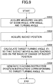
- FIG. 9 is a flowchart schematically illustrating an example of turning automatic control processing performed with the controller 30.
- the processing according to this flowchart is repeatedly executed with a predetermined time, i.e., with a predetermined control cycle T during operation of the shovel 500.
- step S902 the bucket position information acquiring unit 302 acquires the measured values of the boom angle, the arm angle, and the turning angle received from the boom angle sensor 40, the arm angle sensor 42, and the resolver 22, respectively.
- step S904 the bucket position information acquiring unit 302 acquires (calculates) the bucket position on the basis of the measured values of the boom angle, the bucket angle, and the turning angle.
- step S906 on the basis of a latest change of the bucket position, a latest change of the turning angle, and the like, the teaching instruction generation unit 304 calculates the target turning angle 9t so that the bucket 6 moves along the teaching axis.
- step S908 the teaching instruction generation unit 304 generates teaching instruction (position instruction) corresponding to the target turning angle ⁇ t, outputs the teaching instruction (position instruction) to the control instruction output determination unit 305, and terminates the current processing. Therefore, in a case where the "automatic mode" is set as the operation mode of the shovel 500, the teaching instruction is output from the control instruction output determination unit 305 to the inverter 18B.
- the turning operation of the upper turning body 3 is controlled so that the bucket 6 moves along a predetermined axis as seen in the plan view in response to an operation of the attachment by an operator.
- the operation of the attachment may also be automated.
- the operation of the attachment may also be automated.
- the controller 30 automatically generates an operation input to the levers 26A and 26B corresponding to the excavation operation or leveling operation to retract the bucket 6 toward the upper turning body 3 while keeping the position of the bucket 6 almost constant in the height direction. Accordingly, the controller 30 can automatically control the operation of the attachment. In addition, the controller 30 may control the turning operation of the upper turning body 3 so that the bucket 6 moves along a predetermined axis as seen in the plan view in accordance with the position of the bucket 6 corresponding to the automatic control of the attachment and in response to an operation input to the levers 26A and 26B. Accordingly, the shovel 500 can automatically perform linear construction work without relying on an operation input by an operator.
- coordinates of the start point position and the end point position in the plane polar coordinate system in which the origin is on the turning center axis of the upper turning body 3 may be set in advance in an internal memory and the like of the controller 30. Accordingly, the controller 30 can cause the shovel 500 to perform, in a full automatic manner, repeated linear construction work as illustrated in FIG. 4 explained above.
- the bucket 6 is controlled to move along a predetermined axis (teaching axis) in the plan view.
- the bucket 6 may be controlled to move along a predetermined curve or bent line (hereinafter referred to as "teaching curve and the like").
- teaching data corresponding to the teaching curve and the like may be set in response to an operation of the attachment and the like of the shovel 500.
- teaching data of the teaching curve and the like may be set by receiving corresponding data from an external apparatus and receiving an operation input from an operator and the like, without relying on an operation of the attachment and the like of the shovel 500.
- the controller 30 (the teaching instruction generation unit 304) automatically turns the upper turning body 3 so that the bucket 6 moves along a predetermined teaching axis as seen in the plan view in response to an operation of the attachment with the operating apparatus 26.
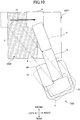
- FIG. 10 is a drawing explaining the second example of an operation of the shovel 500 in the automatic mode.
- the shovel 500 performs excavation work on a construction target surface 1001 in a substantially rectangular shape in the plan view.
- a part (area 1002) of the construction target surface in FIG. 10 needs to be constructed as an inclined surface inclined from the left to the right in FIG. 10 by excavation work. Therefore, it is desired to advance the excavation work in such a manner that the bucket 6 moves in a left-and-right direction of FIG. 10 , which is the inclination direction of the inclined surface.
- the shovel 500 is arranged at a lower side of FIG.
- the upper turning body 3 is automatically turned so that the bucket 6 moves from the left to the right along the axis in the left-and-right direction (hereinafter referred to as "left-and-right axis") in response to an operation of the attachment by an operator. Accordingly, the shovel 500 can achieve more appropriate construction work irrespective of the environmental conditions of construction sites.
- the teaching data may be set by operating the shovel 500 using a method similar to the case of FIG. 5 in a state in which the turning position of the upper turning body 3 is adjusted so that the direction of the attachment is in the left-and-right direction of the construction target surface 1001 in FIG. 10 .
- the teaching data may be set by receiving corresponding data from an external apparatus and receiving an operation input from an operator and the like, without relying on an operation of the attachment and the like of the shovel 500.
- turning automatic controls similar to the above i.e., turning automatic controls for moving the bucket 6 along a teaching axis direction that is greatly different from the direction of the attachment in the plan view, can also be naturally applied to not only excavation work but also work other than the excavation work such as, e.g., leveling work, compaction work, and the like.
- the bucket 6 includes not only a rotation axis for rotating in a vertical direction with respect to the arm 5 but also a rotation axis for rotating in a horizontal direction, so that the bucket 6 can be adjusted in the excavation direction (left-and-right direction). Accordingly, even in a case where the difference between the direction of the attachment and the excavation direction is relatively large, the bucket 6 can rotate in the left-and-right direction by a hydraulic actuator (for example, a hydraulic motor) driven with hydraulic oil provided from the main pump 14, in a manner similar to the case of the rotation operation in the front-rear direction, and an operator and the like can appropriately adjust the direction of the bucket 6 with a predetermined operation means. Also, the direction of the bucket 6 in the plan view may be automatically adjusted in an excavation direction by, for example, causing the controller 30 to automatically adjust the direction and the flowrate of the hydraulic oil supplied to and discharged from the hydraulic actuator.
- a hydraulic actuator for example, a hydraulic motor
- the above construction work may be performed by a generally-available bucket 6 that does not have a rotation axis capable of rotating in the left-and-right direction.
- the vertical position of the bucket 6 may be automatically controlled so that, in accordance with a movement of the bucket 6 in the left-and-right direction, the teeth position of the bucket 6 moves along the target construction surface corresponding to the constructed inclined surface, or moves within a range not interfering with the target construction surface. Accordingly, in a case where, in the plan view, the direction of the attachment and the movement direction of the bucket 6 are greatly different, an operator can move the bucket 6 in such a manner that the inclined surface can be appropriately constructed. Therefore, the construction quality can be further improved. At this occasion, for example, a configuration similar to FIG.
- a proportional valve 31 and a shuttle valve 32 is employed, and at least one of the boom 4, the arm 5, and the bucket 6 is automatically controlled, so that the controller 30 can control the vertical position of the bucket 6.
- the controller 30 controls the vertical position of the bucket 6, the controller 30 can find the position of the bucket 6 on the basis of detection signals of the boom angle sensor 40, the arm angle sensor 42, and the bucket angle sensor.
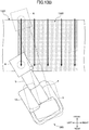
- FIG. 11 is a drawing explaining the third example of operation of the shovel 500 in the automatic mode.
- the shovel 500 performs compaction work while pressing the back of the bucket 6 against the ground.
- the shovel 500 operates the attachment so that the bucket 6 is pressed against the ground while the bucket 6 is retracted toward the operator's side (toward the upper turning body 3) in response to an operator's operation.
- the shovel 500 automatically repeats reciprocal motion of the upper turning body 3 in the left-and-right direction to compact an area 1102 in the construction target surface 1101 having a certain width wider than the width of the bucket 6.
- the controller 30 controls the turning operation of the upper turning body 3 so that the bucket 6 automatically repeats reciprocal motion in the left-and-right direction. Accordingly, an area having a width wider than the width of the bucket 6 can be efficiently compacted.
- the teaching data may include, for example, data corresponding to the width of the area 1102 and data corresponding to a movement speed in the left-and-right direction, and the like.
- the teaching data may be data corresponding to a movement trace of the bucket 6 in the plan view (for example, trace data corresponding to thick arrows in a zigzag shape in FIG. 11 ).
- the teaching data may be set by receiving corresponding data from an external apparatus and receiving an operation input from an operator and the like, without relying on an operation of the attachment and the like of the shovel 500. In the latter case, for example, the teaching data may be set by recording the trace of the movement of the bucket 6 in response to an operator's operation.
- the leveling work of the shovel 500 may be performed by sweeping away small protrusions on the ground to the right and left by repeating reciprocal motion of the upper turning body 3 in the left-and-right direction in accordance with a movement of the attachment in the front-rear direction.
- the movement direction of the attachment may be in a direction in which the bucket 6 moves away from the upper turning body 3, i.e., in a direction from the operator's side toward the front of the upper turning body 3, instead of in a direction in which the bucket 6 approaches the upper turning body 3, i.e., in a direction from the front of the upper turning body 3 toward the operator's side (toward the upper turning body 3).
- FIG. 12 FIG. 13 ( FIG. 13A , FIG. 13B ).
- FIG. 12 is a block diagram illustrating another example of a configuration of the shovel 500. Hereinafter, differences from the example in FIG. 2 will be mainly explained.
- An operation system of the shovel 500 according to this example includes a pilot pump 15, an operating apparatus 26, a pressure sensor 29, and a shuttle valve 32.
- the control system of the shovel 500 according to this example includes a controller 30, an ECM 75, an engine speed sensor 11a, an inverter 18A, an inverter 18B, a current sensor 21s, a resolver 22, a boom angle sensor 40, an arm angle sensor 42, a teaching mode switch 44, a teaching data setting switch 46, an automatic mode switch 48, and a proportional valve 31.
- the operating apparatus 26 is connected to the control valve 17 via a later-described shuttle valve 32 provided in a secondary-side pilot line. Accordingly, the control valve 17 may receive a pilot pressure according to the state of operation of each of the lower traveling body 1, the upper turning body 3, the boom 4, the arm 5, and the bucket 6, and the like in the operating apparatus 26. Therefore, the control valve 17 can drive the hydraulic actuators in accordance with the state of operation in the operating apparatus 26.
- the proportional valve 31 is provided in a pilot line connecting the pilot pump 15 and the shuttle valve 32, and configured to be able to change the size of area of flow (i.e., the size of a cross-sectional area in which hydraulic oil can flow).
- the proportional valve 31 operates in accordance with a control instruction received from the controller 30. Accordingly, even in a case where an operator is not operating the operating apparatus 26, the controller 30 can provide hydraulic oil discharged from the pilot pump 15 via the proportional valve 31 and the shuttle valve 32 to a pilot port in a corresponding control valve in the control valve 17.
- the shuttle valve 32 has two inlet ports and one outlet port, and outputs one of hydraulic oils input to the two inlet ports, whichever has a higher pilot pressure, to the outlet port.
- the shuttle valve 32 has one of the two inlet ports connected to the operating apparatus 26 and the other of the two inlet ports connected to the proportional valve 31.
- the outlet port of the shuttle valve 32 is connected via the pilot line to a pilot port in a corresponding control valve in the control valve 17. Therefore, the shuttle valve 32 can apply the pilot pressure generated by the operating apparatus 26 and the pilot pressure generated by the proportional valve 31, whichever is higher, to the pilot port of the corresponding control valve.
- the controller 30 can control the corresponding control valve, and automatically control an operation of the lower traveling body 1 and the attachment AT, without relying on an operation performed with the operating apparatus 26 by an operator.
- FIG. 13A , FIG. 13B are drawings for explaining the fourth example of operation of the shovel 500 in the automatic mode.
- FIG. 13A is a side view of an inclined land 1301, which is a construction target to be constructed by the shovel 500, and a slope BS, which is a target construction surface.
- FIG. 13B is a drawing illustrating a specific example of operation in which the shovel 500 constructs the slope BS.
- the shovel 500 automatically operates the attachment and the upper turning body 3 to perform earth cutting work and compaction work so that the bucket 6 forms the slope BS in a previously-set work range 1302 of the inclined land 1301.
- the shovel 500 is arranged at a position facing the work range 1302, and in this state, the work range 1302 is set.
- the controller 30 (the teaching instruction generation unit 304) automatically controls the attachment (the boom 4, the arm 5, and the bucket 6) and the upper turning body 3, so that, for each of multiple lanes (for example, five thick arrows in FIG. 13B ) defined in the inclination direction in the work range 1302, the bucket 6 moves from the farther side toward the operator's side (the upper turning body 3) along the teaching axis set in the inclination direction, and a teeth end (during earth cutting) or a rear surface (during compaction) of the bucket 6 moves along the slope BS.
- multiple lanes for example, five thick arrows in FIG. 13B
- the controller 30 automatically controls the operation of the attachment and the upper turning body 3 while finding the positions of the teeth end and the rear surface of the bucket 6 on the basis of detection signals provided by the boom angle sensor 40, the arm angle sensor 42, and the bucket angle sensor. Accordingly, with just the work range 1302 being set, the shovel 500 can be caused to automatically perform the construction work of the slope BS in the work range 1302.
- the work range 1302 may be set by receiving an operation input from an operator and the like, and for example, the work range 1302 may be set by receiving data corresponding to the work range 1302 from a predetermined external apparatus via a communication apparatus.
- a lane in which the bucket 6 moves along the teaching axis as seen in the plan view may be set in advance together with the configuration of the work range 1302, or the controller 30 may automatically derive the lane in accordance with the width of the work range 1302 in the left-and-right direction as seen from the upper turning body 3.
- the controller 30 recognizes a construction situation of the slope BS, and continues the construction work of the slope BS until the construction of the slope BS is completed with a predetermined quality. Accordingly, with just the work range 1302 being set, the shovel 500 can be caused to automatically perform the construction work of the slope BS in the work range 1302 until a predetermined quality is reached, i.e., until the construction is finished.
- examples of spatial recognition apparatuses include a monocular camera, a LIDAR (Light Detecting and Ranging), a millimeter wave radar, a stereo camera, a distance image camera, an ultrasonic sensor, an infrared sensor, and the like.
- the controller 30 controls the turning operation of the upper turning body 3 so that the bucket 6 performs a predetermined operation as seen in the plan view.
- the controller 30 can perform a predetermined operation in which the position of the bucket 6 is caused to move not only in the front-rear direction but also in the left-and-right direction as seen from the upper turning body 3. Therefore, the width of the work of the shovel 500 can be expanded, and the work efficiency of the shovel 500 can be improved.
- the bucket 6 is used as an end attachment, an end attachment other than the bucket 6 may be adopted.
- the controller 30 may control the turning operation of the upper turning body 3 in response to an operation of the attachment, so that the bucket 6 performs a predetermined operation (hereinafter referred to as an "instructed operation" for convenience) in the plan view in response to an operator's operation, i.e., an operation of the attachment including the boom 4 and the arm 5 performed by an operator.
- a predetermined operation hereinafter referred to as an "instructed operation” for convenience
- the controller 30 can perform a predetermined instructed operation in a specific manner by causing the upper turning body 3 to operate in accordance with an operation of the attachment in response to an operator's operation.
- the controller 30 may automatically control the operation of the attachment and the upper turning body 3 so that the bucket 6 performs a predetermined processing (for example, forming of the slope BS) in the work range.
- the shovel 500 can be caused to perform a predetermined processing on the work range automatically and efficiently.
- the controller 30 may control the turning operation of the upper turning body 3, so that the bucket 6 repeats movement in the left-and-right direction in the plan view in accordance with a movement of the attachment in the front-rear direction in response to an operator's operation.
- the shovel 500 can perform construction work on a range wider than the width of the bucket 6 as a target, and therefore, the work efficiency can be further improved.
- the controller 30 may control the turning operation of the upper turning body 3 so that the bucket 6 performs a predetermined instructed operation as seen in the plan view.
- the controller 30 may control the turning operation of the upper turning body 3, so that the bucket 6 moves along the predetermined axis (teaching axis) in the plan view in response to an operator's operation, i.e., an operation of the attachment including the boom 4 and the arm 5 by an operator.
- an operator can move the bucket 6 along the teaching axis by just operating the attachment such as the boom 4 and the arm 5 with the levers 26A and 26B.
- the attachment such as the boom 4 and the arm 5 with the levers 26A and 26B.
- an operator can move the bucket 6 along the predetermined construction direction by just operating the levers 26A and 26B corresponding to the attachment.
- the linear construction can be performed with only an operation of the attachment without relying on the arrangement of the shovel 500 as seen in the plan view, and accordingly, the workability of an operator can be improved, and the work efficiency of construction work can be improved.
- the energy efficiency of the shovel 500 i.e., the fuel consumption rate, can be improved.
- an operator can concentrate on an operation of an attachment such as the boom 4 and the arm 5, i.e., an operation of the attachment in the height direction, and therefore, the accuracy of construction work can be improved.
- an attachment such as the boom 4 and the arm 5, i.e., an operation of the attachment in the height direction, and therefore, the accuracy of construction work can be improved.
- the construction surface can be finished more neatly, and the construction quality can be improved.
- the bucket position information acquiring unit 302 acquires bucket position information about the position of the bucket 6 with reference to the lower traveling body 1. Then, on the basis of the bucket position information acquired by the bucket position information acquiring unit 302, the teaching instruction generation unit 304 may control the turning operation of the upper turning body 3 so that the bucket 6 moves along a predetermined axis (teaching axis) in the plan view.
- the teaching instruction generation unit 304 can control the turning operation of the upper turning body 3 so that the bucket 6 moves along the teaching axis as seen in the plan view.
- the boom angle sensor 40 detects the angle of the boom 4 with respect to the upper turning body 3, and the arm angle sensor 42 detects the angle of the arm 5 with respect to the boom 4. Then, the bucket position information acquiring unit 302 may acquire bucket position information on the basis of detection results of the boom angle sensor 40 and the arm angle sensor 42.
- the bucket position information acquiring unit 302 can obtain relative bucket position information with respect to the lower traveling body 1 on the basis of the link length of the boom 4 and the arm 5, the boom angle, and the arm angle, which are known.
- the lower traveling body 1 or the upper turning body 3 may be equipped with a distance sensor such as a millimeter wave radar or a LIDAR or another sensor including an image sensor (camera), and the bucket position information may be acquired from a detection result of the another sensor.
- a distance sensor such as a millimeter wave radar or a LIDAR or another sensor including an image sensor (camera)
- the bucket position information may be acquired from a detection result of the another sensor.
- the bucket position information acquiring unit 302 may acquire, as the bucket position information, a measured value of a distance from the turning center axis of the upper turning body 3 with respect to the lower traveling body 1 and a measured value of the turning angle of the upper turning body 3.
- the bucket position information acquiring unit 302 can acquire, as the bucket position information, a radial coordinate (a distance from the turning center axis) and an angular coordinate (a turning angle) in a plane polar coordinate system in which the origin is on the turning center axis of the upper turning body 3 with respect to the lower traveling body 1 as seen in the plan view.
- the teaching instruction generation unit 304 may calculate the target value of the turning angle so that the bucket 6 moves along a predetermined axis (teaching axis) in the plan view, and may control the turning operation of the upper turning body 3 so that the turning angle of the upper turning body 3 attains the calculated target value.
- the teaching instruction generation unit 304 can calculate a target value of the turning angle (target turning angle), and perform position control of the upper turning body 3 so that the bucket 6 moves in the teaching axis as seen in the plan view.
- an automatic mode switch 48 is provided to cause the operation mode of the shovel 500 to transit to "automatic mode” in which the upper turning body 3 is automatically turned by the teaching instruction generation unit 304. Then, in a case where the "automatic mode" is set on the basis of an operation input performed with the automatic mode switch 48, the teaching instruction generation unit 304 may control the turning operation of the upper turning body 3 so that the bucket 6 moves along a predetermined axis (teaching axis) in the plan view in accordance with an operation of the attachment including the boom 4 and the arm 5 performed by an operator.
- an operator can set and cancel the automatic mode in accordance with an operator's operation with the automatic mode switch 48. Therefore, in a case where linear construction work is repeatedly performed along a predetermined axis, and an operator proceeds to subsequent construction work, the operator operates the automatic mode switch 48 to cancel the automatic mode, so that the operator can manually operate the upper turning body 3 to move the bucket 6 to a start position of subsequent construction work.
- the teaching mode switch 44 is provided to cause the operation mode of the shovel 500 to transit to the "teaching mode" in which a predetermined axis (teaching axis) can be set. Furthermore, in a case where the "teaching mode" is set on the basis of an operation input to the teaching mode switch 44, the teaching data setting unit 303 may set a predetermined axis (teaching axis) in accordance with an operation of the attachment including the boom 4 and the arm 5 performed by an operator.
- the operator can set the teaching axis.
- the teaching data setting unit 303 acquires position information about a first position (first end point) of the bucket 6 and position information about a second position (second end point) of the bucket 6 different from the first position, in accordance with an operation of the boom 4 and the arm 5 performed by an operator. Then, the teaching data setting unit 303 sets a predetermined axis (teaching axis) on the basis of the position information about the first position and the second position.
- the teaching data setting unit 303 can acquire position information about two different positions between which the bucket 6 is moved when an operator operates the attachment including the boom 4 and the arm 5, and a teaching axis can be set as a line segment or a vector connecting the two points.
- an inclination sensor is provided to detect an inclination of a work surface where the shovel 500 is located. Then, on the basis of the inclination sensor, the teaching instruction generation unit 304 may control the turning operation of the upper turning body 3 so that the bucket 6 moves along a predetermined axis (teaching axis) in the plan view.
- the teaching instruction generation unit 304 can control the turning operation of the upper turning body 3 in view of the measured value of the inclination of the work surface. Therefore, the teaching instruction generation unit 304 can control the turning operation of the upper turning body 3 so that the bucket 6 appropriately moves along a predetermined axis (teaching axis) in the plan view, irrespective of the inclination of the work surface of the shovel 500.
- the teaching instruction generation unit 304 may control the turning operation of the upper turning body 3 by controlling the turning electric motor 21.
- the turning automatic control of the upper turning body 3 can be achieved relatively easily. Since the turning electric motor 21 has a relatively high responsiveness to the drive instruction, the followability to the teaching axis as seen in the plan view of the bucket 6 can be improved.
- a turning hydraulic motor hydraulically driving the upper turning body 3 may be employed instead of the turning electric motor 21, a turning hydraulic motor hydraulically driving the upper turning body 3 may be employed.
- the control valve 17 is additionally provided with a direction control valve (hereinafter referred to as "turning direction control valve") for supplying hydraulic oil from the main pump 14 to the turning hydraulic motor.
- the normal instruction generation unit 301 and the teaching instruction generation unit 304 generates, as a normal instruction and a teaching instruction, respectively, control instructions for driving the turning hydraulic motor, i.e., control instructions for controlling the turning direction control valve.
- control instruction output determination unit 305 may output any one of the normal instruction and the teaching instruction to a turning direction control valve (in the case of electric drive) or a pressure reducing valve for controlling the pilot pressure of the turning direction control valve (in the case of pilot pressure drive).
Landscapes
- Engineering & Computer Science (AREA)
- Mining & Mineral Resources (AREA)
- Civil Engineering (AREA)
- General Engineering & Computer Science (AREA)
- Structural Engineering (AREA)
- Mechanical Engineering (AREA)
- Business, Economics & Management (AREA)
- Educational Administration (AREA)
- Entrepreneurship & Innovation (AREA)
- Physics & Mathematics (AREA)
- Educational Technology (AREA)
- General Physics & Mathematics (AREA)
- Theoretical Computer Science (AREA)
- Paleontology (AREA)
- General Life Sciences & Earth Sciences (AREA)
- Life Sciences & Earth Sciences (AREA)
- Operation Control Of Excavators (AREA)
Abstract
Description
- The present invention relates to a shovel.
- For example, construction such as excavation and leveling is performed using a shovel (for example, Patent Document 1).
- Patent Document 1: Japanese Unexamined Patent Publication No.
2012-103262 - However, when construction such as excavation and leveling is performed with an end attachment such as a bucket, it is necessary to align an extension direction of an attachment including a boom, an arm, and the like with a construction direction (an excavation direction and a leveling direction). In other words, depending on a location where construction is performed, it is necessary to position a shovel with a traveling body, or it is necessary to make correction with an operation of a turning body. Therefore, there is room for improvement from the viewpoint of work efficiency in construction.
- In view of the above problems, it is an object of the present invention to provide a shovel that can further improve work efficiency during construction with an attachment.
- In order to achieve the above object, according to an embodiment of the present invention, provided is a shovel including:
- a traveling body;
- a turning body turnably mounted on the traveling body;
- a work attachment including a boom attached to the turning body, an arm attached to an end of the boom, and an end attachment attached to an end of the arm; and
- a control unit configured to control a turning operation of the turning body to cause the end attachment to perform a predetermined operation as seen in a plan view.
- According to the above-described embodiment, a shovel that can further improve work efficiency during construction with an attachment can be provided.
-
-
FIG. 1 is a side view of a shovel. -
FIG. 2 is a block diagram illustrating an example of a configuration of the shovel. -
FIG. 3 is a functional block diagram illustrating an example of a functional configuration of the shovel. -
FIG. 4 is a drawing illustrating an example of construction work of the shovel. -
FIG. 5 is a drawing illustrating an example of a setting method of teaching data (teaching axis) in a teaching mode. -
FIG. 6 is a drawing explaining a first example of an operation of the shovel in an automatic mode. -
FIG. 7 is a drawing illustrating an example of a turning control method in the automatic mode. -
FIG. 8 is a flowchart schematically illustrating an example of teaching data setting processing by a controller. -
FIG. 9 is a flowchart schematically illustrating an example of turning automatic control processing by the controller. -
FIG. 10 is a drawing explaining a second example of the operation of the shovel in the automatic mode. -
FIG. 11 is a drawing explaining a third example of the operation of the shovel in the automatic mode. -
FIG. 12 is a block diagram illustrating another example of the configuration of the shovel. -
FIG. 13A is a drawing explaining a fourth example of the operation of the shovel in the automatic mode. -
FIG. 13B is a drawing explaining the fourth example of the operation of the shovel in the automatic mode. - Hereinafter, an embodiment of the invention will be described with reference to the drawings.
- First, a configuration of a
shovel 500 according to this embodiment will be described with reference toFIG. 1 . -
FIG. 1 is a side view of theshovel 500 according to this embodiment. - The
shovel 500 according to this embodiment includes a lower travelingbody 1, an upper turningbody 3 turnably mounted on the lower travelingbody 1 via aturning mechanism 2, aboom 4, anarm 5, abucket 6, and acabin 10 in which an operator rides. Theboom 4, thearm 5, and thebucket 6 serve as an attachment (an example of a work attachment). - The lower traveling body 1 (an example of a traveling body) includes, for example, a pair of left and right crawlers, which are hydraulically driven by traveling
hydraulic motors FIG. 2 ), respectively, to cause theshovel 500 to travel. - The upper turning body 3 (an example of a turning body) is driven by a turning electric motor 21 (see
FIG. 2 ), which will be described below to turn relative to thelower traveling body 1. - The
boom 4 is pivotally attached to the front center of the upper turningbody 3 to be able to vertically pivot, thearm 5 is pivotally attached to the end of theboom 4 to be able to pivot vertically, and the bucket 6 (an example of an end attachment) is pivotally attached to the end of thearm 5. Theboom 4, thearm 5, and thebucket 6 are hydraulically driven by aboom cylinder 7, anarm cylinder 8, and abucket cylinder 9, respectively, which serve as hydraulic actuators. - The
cabin 10, which is an operator room in which an operator rides, is mounted on the front left of the upper turningbody 3. - Next, a basic configuration of the
shovel 500 will be described with reference toFIG. 2 . -
FIG. 2 is a block diagram illustrating an example of a configuration of theshovel 500 according to this embodiment. - In drawing, a mechanical power line, a high-pressure hydraulic line, a pilot line, and an electric drive and control system are indicated by a double line, a thick solid line, a dashed line, and a thin solid line, respectively.
- A hydraulic drive system that hydraulically drives hydraulic actuators of the
shovel 500 according to this embodiment includes anengine 11, anelectric motor 12, aspeed reducer 13, amain pump 14, and acontrol valve 17. As described above, the hydraulic drive system of theshovel 500 according to this embodiment includes hydraulic actuators such as the travelinghydraulic motors boom cylinder 7, thearm cylinder 8, and thebucket cylinder 9, which hydraulically drive the lower travelingbody 1, theboom 4, thearm 5, and thebucket 6, respectively. - The
engine 11 is a main power source in the hydraulic drive system, and is mounted on the rear part of the upper turningbody 3, for example. Specifically, under the control of an engine control module (ECM: Engine Control Module) 75, which will be described later, theengine 11 rotates constantly at a preset target rotational speed, and drives themain pump 14 and apilot pump 15 via thespeed reducer 13. In addition, theengine 11 drives theelectric motor 12 via the speed reducer 13 so that theelectric motor 12 can generate electric power. Theengine 11 is, for example, a diesel engine using light oil as fuel. - The
electric motor 12 is an assist power source in the hydraulic drive system that assists theengine 11 in driving themain pump 14. For example, theelectric motor 12 is mounted, together with theengine 11 and the speed reducer 13, as a unit, on the rear part of the upper turningbody 3. Theelectric motor 12 is connected to an electricpower storage system 120 including acapacitor 19 via aninverter 18A. Theelectric motor 12 performs power running operation with electric power supplied from thecapacitor 19 or the turningelectric motor 21 via theinverter 18A to drive themain pump 14 and thepilot pump 15 via thespeed reducer 13. In addition, theelectric motor 12 can be driven by theengine 11 to perform a generator operation to supply the generated power to thecapacitor 19 and the turningelectric motor 21. The switching between the power running operation and the generator operation of theelectric motor 12 can be controlled by controlling the drive of theinverter 18A with acontroller 30 described later. - The
speed reducer 13 is mounted on the rear part of the upper turningbody 3, for example, like theengine 11, and includes two input shafts to which theengine 11 and theelectric motor 12 are connected, and one output shaft to which themain pump 14 and thepilot pump 15 are coaxially connected in series. Thespeed reducer 13 can transmit the power of theengine 11 and theelectric motor 12 to themain pump 14 and thepilot pump 15 at a predetermined reduction ratio. Thespeed reducer 13 can distribute and transmit the power of theengine 11 to theelectric motor 12, themain pump 14, and thepilot pump 15 at a predetermined reduction ratio. - The
main pump 14 is mounted, for example, on the rear part of theupper turning body 3, like theengine 11, and supplies hydraulic oil to thecontrol valve 17 through a high-pressurehydraulic line 16. Themain pump 14 is driven by theengine 11, or by theengine 11 and theelectric motor 12. Themain pump 14 is, for example, a variable displacement hydraulic pump, in which a regulator (not illustrated) controls the angle (tilt angle) of a swash plate to adjust the stroke length of a piston under the control of thecontroller 30 described later, so that the discharge flow rate (discharge pressure) can be controlled. - The
control valve 17 is a hydraulic control device that is installed, for example, at the center of theupper turning body 3, and that controls the hydraulic drive system in accordance with an operator's operation of anoperating apparatus 26. Thecontrol valve 17 is connected to themain pump 14 via the high-pressurehydraulic line 16 as described above, and hydraulic oil supplied from themain pump 14 is selectively supplied to the travelinghydraulic motors 1A (for right), 1B (for left), theboom cylinder 7, thearm cylinder 8, and thebucket cylinder 9 according to the operating state of theoperating apparatus 26. Specifically, thecontrol valve 17 is a valve unit including multiple hydraulic control valves (directional control valves) that control the flow rate and the flow direction of hydraulic oil supplied from themain pump 14 to each of the hydraulic actuators. - An electric drive system that drives an electric actuator of the
shovel 500 according to this embodiment includes the turningelectric motor 21, amechanical brake 23, and aturning speed reducer 24. - The turning electric motor 21 (an example of an electric motor) is an electric actuator that drives the
turning mechanism 2 that turnably connects theupper turning body 3 to thelower traveling body 1, such that theupper turning body 3 can turn relative to thelower traveling body 1. The turningelectric motor 21 performs power running operation to turn theupper turning body 3, and performs regenerative operation to generate regenerative power and brake the turning of theupper turning body 3, under the control of thecontroller 30. The turningelectric motor 21 is connected to the electricpower storage system 120 via aninverter 18B, and is driven by electric power supplied from thecapacitor 19 or theelectric motor 12 via theinverter 18B. The turningelectric motor 21 supplies regenerative power to thecapacitor 19 and theelectric motor 12 via theinverter 18B. This allows thecapacitor 19 to be charged and theelectric motor 12 to be driven with the regenerative power. The switching between the power running operation and the regenerative operation of the turningelectric motor 21 can be controlled by controlling the drive of theinverter 18B with thecontroller 30. Aresolver 22, themechanical brake 23, and theturning speed reducer 24 are connected to arotating shaft 21A of the turningelectric motor 21. - The
mechanical brake 23 mechanically generates a braking force for the upper turning body 3 (specifically, therotating shaft 21A of the turning electric motor 21) under the control of thecontroller 30 to keep theupper turning body 3 in a stopped state. In addition, for example, when theupper turning body 3 needs to be stopped for an emergency, themechanical brake 23 may brake the turning of theupper turning body 3. - In
FIG. 2 , theturning speed reducer 24 and themechanical brake 23 are described as separate block elements for simplicity, but themechanical brake 23 may be, for example, a hydraulic disc brake installed between multiple speed reducers included in theturning speed reducer 24, or may be an electromagnetic brake provided separately from theturning speed reducer 24. - The
turning speed reducer 24 is connected to therotating shaft 21A of the turningelectric motor 21. By reducing the speed of the output of the turningelectric motor 21 at a predetermined reduction ratio, the torque is increased and theupper turning body 3 is turned. That is, during power running operation, the turningelectric motor 21 turns theupper turning body 3 via theturning speed reducer 24. In addition, theturning speed reducer 24 increases the inertial rotation force of theupper turning body 3 and transmits the inertial rotation force to the turningelectric motor 21 to generate regenerative power. That is, during the regenerative operation, the turningelectric motor 21 performs regenerative power generation by the inertial rotation force of theupper turning body 3 transmitted via theturning speed reducer 24 to brake theupper turning body 3. - The electric
power storage system 120, which is a power supply for driving theelectric motor 12 and the turningelectric motor 21 of theshovel 500 according to this embodiment, includes acapacitor 19, aDC bus 100, and a buck-boost converter 110. For example, the electricpower storage system 120 is mounted on the right front portion of theupper turning body 3 together with theinverters - The
capacitor 19 supplies power to theelectric motor 12 and the turningelectric motor 21, and conversely, thecapacitor 19 is charged to store the generated power of theelectric motor 12 and the turningelectric motor 21 supplied via theDC bus 100 and the buck-boost converter 110. - The
DC bus 100 is provided between theinverters boost converter 110, and controls the transfer of electric power between thecapacitor 19, theelectric motor 12, and the turningelectric motor 21. - The buck-
boost converter 110 switches between a step-up operation and a step-down operation so that the voltage value of theDC bus 100 falls within a certain range according to the operating state of theelectric motor 12 and the turningelectric motor 21. Thus, power is transferred between thecapacitor 19, theelectric motor 12, and the turningelectric motor 21. The switching control between the step-up operation and the step-down operation of the buck-boost converter 110 is achieved by thecontroller 30 based on the detected voltage value of theDC bus 100, the detected voltage value of thecapacitor 19, and the detected current value of thecapacitor 19. - The operation system of the
shovel 500 according to this embodiment includes thepilot pump 15, the operatingapparatus 26, and apressure sensor 29. - The
pilot pump 15 is installed, for example, on the rear part of theupper turning body 3, and applies a pilot pressure to theoperating apparatus 26 via apilot line 25. For example, thepilot pump 15 is a fixed displacement hydraulic pump, and is driven by theengine 11 or by theengine 11 and theelectric motor 12. - The
operating apparatus 26 includeslevers 26A and 26B, and a pedal 26C. Theoperating apparatus 26 is provided near the operator's seat of thecabin 10, and is an operation input means for operating operational elements (such as thelower traveling body 1, theupper turning body 3, theboom 4, thearm 5, and the bucket 6) by the operator. In other words, the operatingapparatus 26 is an operation input means for operating the hydraulic actuators (such as the travelinghydraulic motors boom cylinder 7, thearm cylinder 8, the bucket cylinder 9), and an electric actuator (the turning electric motor 21), which drive the respective operational elements. Hereinafter, the description will be given based on the assumption that the operations of the attachment including theboom 4, thearm 5, and thebucket 6 and the operation of theupper turning body 3 are performed by thelevers 26A and 26B. The operating apparatus 26 (thelevers 26A and 26B, and the pedal 26C) is connected to thecontrol valve 17 via ahydraulic line 27. Thecontrol valve 17 receives a pilot signal (pilot pressure) corresponding to the state of operation of each of thelower traveling body 1, theboom 4, thearm 5, and thebucket 6 performed with theoperating apparatus 26. Accordingly, thecontrol valve 17 can drive each of the hydraulic actuators in accordance with the state of operation performed with theoperating apparatus 26. Theoperating apparatus 26 is connected to thepressure sensor 29 via ahydraulic line 28. - As described above, the
pressure sensor 29 is connected to theoperating apparatus 26 via thehydraulic line 28, detects the secondary-side pilot pressure of theoperating apparatus 26, i.e., the pilot pressure corresponding to the state of operation of each of the operational elements (the hydraulic actuators and the electric actuator) performed with theoperating apparatus 26. Thepressure sensor 29 is communicably connected to thecontroller 30 through a one-to-one communication line or an in-vehicle network such as a CAN. A pressure signal (a detected value of the pilot pressure) corresponding to the state of operation of each of thelower traveling body 1, theupper turning body 3, theboom 4, thearm 5, and thebucket 6 performed with theoperating apparatus 26 is input into thecontroller 30. - The control system of the
shovel 500 according to this embodiment includes acontroller 30, anECM 75, anengine speed sensor 11a, theinverter 18A, theinverter 18B, acurrent sensor 21s, and theresolver 22. The control system of theshovel 500 according to this embodiment includes, as a configuration about a turning automatic control explained later, aboom angle sensor 40, anarm angle sensor 42, ateaching mode switch 44, a teachingdata setting switch 46, and anautomatic mode switch 48. - The
controller 30 is a control device that performs drive control of theshovel 500. For example, thecontroller 30 performs drive control of theengine 11 via theECM 75 based on a work mode or the like set in advance by a predetermined operator's operation or the like. Thecontroller 30 controls the driving of theelectric motor 12 and the turningelectric motor 21 via theinverters pressure sensor 29, corresponding to the state of operation of each of operation elements (i.e., various hydraulic actuators and the electric actuator) performed with theoperating apparatus 26. In addition, as described above, thecontroller 30 performs switching control between the step-up operation and the step-down operation of the buck-boost converter 110 on the basis of the detected voltage value of theDC bus 100, the detected voltage value of thecapacitor 19, and the detected current value of thecapacitor 19. Thecontroller 30 automatically controls the turning operation of theupper turning body 3 so that thebucket 6 automatically performs an operation according to predetermined teaching data, in accordance with an operation of the attachment including theboom 4 and thearm 5 performed by an operator with the use of theoperating apparatus 26 or without relying on an operator's operation. Hereinafter, the control mode of theupper turning body 3 by thecontroller 30 is referred to as "turning automatic control". The details of the "turning automatic control" by thecontroller 30 will be described later. - The functions of the
controller 30 may be achieved by any hardware, software, or a combination thereof. For example, thecontroller 30 is constituted by a microcomputer including a CPU (Central Processing Unit), a ROM (Read Only Memory), a RAM (Random Access Memory), an auxiliary storage device, an I/O (Input-Output interface), and the like. Various functions are achieved by causing the CPU to execute various programs stored in the ROM and the auxiliary storage device. - Some of the functions of the
controller 30 may be achieved by another controller. That is, the function of thecontroller 30 may be achieved as being distributed across multiple controllers. - The
ECM 75 drives and controls theengine 11 based on the control instruction from thecontroller 30. For example, theECM 75 generates a torque instruction of theengine 11 so as to cause theengine 11 to constantly rotate at a target rotational speed corresponding to the control instruction from thecontroller 30, on the basis of a measured value of the rotational speed of theengine 11 corresponding to the detection signal received from theengine speed sensor 11a. Then, theECM 75 outputs, to actuators such as a fuel injection device and the like of theengine 11, a drive instruction for causing theengine 11 to generate a torque according to the generated torque instruction. - The
engine speed sensor 11a is a known detection means for detecting the rotational speed of theengine 11. Theengine speed sensor 11a is communicably connected to theECM 75 through a one-to-one communication line or an in-vehicle network such as a CAN. A detection signal corresponding to the rotational speed of theengine 11 is input into theECM 75. - Using the electric
power storage system 120, theinverter 18A outputs a three-phase alternate current power that drives theelectric motor 12, and conversely, supplies the power generated by theelectric motor 12 to the electricpower storage system 120. Specifically, in theinverter 18A, a built-in drive circuit (not illustrated) generates a drive instruction, for example, a PWM (Pulse Width Modulation) instruction, based on a control instruction received from the controller 30 (specifically, a speed instruction for performing a constant rotation at a predetermined rotational speed). Then, in theinverter 18A, based on the drive instruction, a built-in inverter circuit (not illustrated) converts a power supplied from the electricpower storage system 120 into a three-phase alternate current power that drives theelectric motor 12, or conversely, converts a power generated by theelectric motor 12 into a direct current power and supplies the direct current power to the electricpower storage system 120. - The drive circuit for driving the inverter circuit of the
inverter 18A may be provided outside theinverter 18A, for example, in thecontroller 30. - Using the electric
power storage system 120 as a power source, theinverter 18B outputs a three-phase alternate current power for driving the turningelectric motor 21, and conversely, supplies a power generated by the turningelectric motor 21 to the electricpower storage system 120. Specifically, in theinverter 18B, a built-in drive circuit (not illustrated) generates a drive instruction, for example, a PWM (Pulse Width Modulation) instruction, based on a control instruction received from thecontroller 30. Specifically, the drive circuit may generate a drive instruction by performing speed/torque feedback control or position/torque feedback control, on the basis of the rotational speed or rotation position (rotation angle) of the turningelectric motor 21, received from theresolver 22 and thecurrent sensor 21s, and a measured value of an output torque. Then, in theinverter 18B, based on the drive instruction, a built-in inverter circuit (not illustrated) converts a power supplied from the electricpower storage system 120 into a three-phase alternate current power that drives the turningelectric motor 21, or conversely, converts a power generated by the turningelectric motor 21 into a direct current power and supplies the direct current power to the electricpower storage system 120. - The drive circuit for driving the inverter circuit of the
inverter 18B may be provided outside theinverter 18B, for example, in thecontroller 30. - The
current sensor 21s detects the current of each of the three phases (U phase, V phase, W phase) of the turningelectric motor 21. Thecurrent sensor 21s is provided, for example, in a power path between the turningelectric motor 21 and theinverter 18B. Thecurrent sensor 21s is communicably connected to theinverter 18B through a one-to-one communication line or an in-vehicle network such as a CAN. A detection signal corresponding to the current of each of the three phases of the turningelectric motor 21 detected by thecurrent sensor 21s is input into theinverter 18B. - The
current sensor 21s may be built in theinverter 18B to detect the current output from theinverter 18B. In addition, thecurrent sensor 21s may detect the currents of two phases out of the three phases and calculate the current of the remaining one phase from the detected current values of the two phases. The current value of the remaining one phase may be calculated by theinverter 18B (specifically, the drive circuit described above) based on the detection signals corresponding to the current values of two phases input into theinverter 18B. - The
resolver 22 detects the rotation position of the turningelectric motor 21, i.e., the rotation angle with respect to a predetermined reference position in the rotation direction, and the like. In other words, theresolver 22 detects a turning angle with respect to a predetermined reference position in the turning direction of the upper turning body 3 (for example, the turning position of theupper turning body 3 when the extension direction of theboom 4 and the like is the same as the traveling direction of the lower traveling body 1) (hereinafter simply referred to as "turning angle"). Theresolver 22 is communicably connected to theinverter 18B through a one-to-one communication line or an in-vehicle network such as a CAN. A detection signal corresponding to the detected rotation angle (turning angle) is input into theinverter 18B. - The
boom angle sensor 40 detects an elevation angle of theboom 4 with respect to theupper turning body 3, for example, an angle formed by theboom 4 with respect to the turning plane of the upper turning body 3 (hereinafter referred to as "boom angle"). Theboom angle sensor 40 may include, for example, a rotary encoder, an acceleration sensor, an angle acceleration sensor, a six-axis sensor, an IMU (Inertial Measurement Unit), and the like, and hereinafter, this is also applicable to thearm angle sensor 42 and a bucket angle sensor described later. Theboom angle sensor 40 is communicably connected to thecontroller 30 through a one-to-one communication line or an in-vehicle network such as a CAN. A detection signal corresponding to the boom angle is input into thecontroller 30. - The
arm angle sensor 42 detects an orientation angle of thearm 5 with respect to theboom 4, for example, an angle formed by thearm 5 with respect to the boom 4 (hereinafter referred to as "arm angle"). Thearm angle sensor 42 is communicably connected to thecontroller 30 through a one-to-one communication line or an in-vehicle network such as a CAN. A detection signal corresponding to the arm angle is input into thecontroller 30. - It should be noted that, in addition to the
boom angle sensor 40 and thearm angle sensor 42, a bucket angle sensor may be further provided to detect an orientation angle of thebucket 6 with respect to thearm 5, for example, an angle of thebucket 6 with respect to the arm 5 (hereinafter referred to as "bucket angle"). - The teaching mode switch 44 (an example of a teaching mode setting operation unit) is an operation unit provided inside the
cabin 10 to set the operation mode of theshovel 500 to "teaching mode" by an ON/OFF operation or the like by the operator. The "teaching mode" is an operation mode of theshovel 500 for setting the teaching data used in the turning automatic control described above. In the "teaching mode", the turning automatic control is disabled. That is, in the "teaching mode", the turning operation of theupper turning body 3 is controlled by thecontroller 30 in accordance with an operator's operation with theoperating apparatus 26 as usual. Theteaching mode switch 44 may be an operation unit achieved with hardware such as a push button, or may be an operation unit achieved with software such as a button icon and the like displayed on a predetermined display apparatus (for example, a touch panel display and the like mounted in a cabin 10). Hereinafter, this is also applicable to the teachingdata setting switch 46 and theautomatic mode switch 48. Theteaching mode switch 44 is communicably connected to thecontroller 30 through a one-to-one communication line or an in-vehicle network such as a CAN. A signal corresponding to the state of operation (an ON signal or an OFF signal) is input into thecontroller 30. - It should be noted that the teaching data may be set by receiving corresponding data from an external apparatus (for example, a management server and the like for managing a work situation at a work site and an operation situation of a shovel at a work site) via a communication device mounted on the
shovel 500, or receiving an operation input from an operator and the like. Specifically, the teaching data may be set without letting an operator and the like operate the attachment and the like of theshovel 500. - The teaching
data setting switch 46 is an operation unit provided inside thecabin 10 to receive an operator's operation and the like for setting teaching data in the "teaching mode". The teachingdata setting switch 46 is communicably connected to thecontroller 30 through a one-to-one communication line or an in-vehicle network such as a CAN. An operation signal corresponding to the state of operation of the teachingdata setting switch 46 is input into thecontroller 30. A specific operation method and the like of the teachingdata setting switch 46 will be described later. - The automatic mode switch 48 (an example of an automatic mode setting operation unit) is an operation unit provided inside the
cabin 10 to set the operation mode of theshovel 500 to "automatic mode" according to an ON/OFF operation and the like by the operator. The "automatic mode" is an operation mode in which the above-described turning automatic control is effective. Hereinafter, in association with the "automatic mode", an operation mode in which the turning automatic control is not effective except for the "teaching mode", i.e., an operation mode in which, as usual, the turning operation of theupper turning body 3 is controlled by thecontroller 30 in accordance with an operator's operation with theoperating apparatus 26 will be referred to as a "normal mode". The explanation about the "teaching mode" is based on the assumption that the "teaching mode" is included in the "normal mode". Theautomatic mode switch 48 is communicably connected to thecontroller 30 through a one-to-one communication line or an in-vehicle network such as a CAN. A signal (an ON signal or an OFF signal) corresponding to the state of operation is input into thecontroller 30. - Next, a detailed configuration of a turning
control apparatus 200 mounted on theshovel 500 to control the turning operation of theupper turning body 3 will be described with reference toFIG. 3 . - The turning
control apparatus 200 includes thecontroller 30, theinverter 18B, the turningelectric motor 21, theresolver 22, thepressure sensor 29, theboom angle sensor 40, thearm angle sensor 42, theteaching mode switch 44, the teachingdata setting switch 46, and theautomatic mode switch 48. - The
controller 30 includes, as functional units associated with control of the turning operation of theupper turning body 3, a normalinstruction generation unit 301, a bucket positioninformation acquiring unit 302, a teachingdata setting unit 303, a teachinginstruction generation unit 304, and a control instructionoutput determination unit 305. - The normal
instruction generation unit 301 generates a speed instruction, as a normal control instruction for controlling the upper turning body 3 (hereinafter referred to as "normal instruction"), on the basis of the state of operation of theupper turning body 3 with thelever 26A received from thepressure sensor 29, i.e., an operation direction and an amount of operation of thelever 26A. - A bucket position
information acquiring unit 302 acquires information (bucket position information) about a position of the bucket 6 (hereinafter simply referred to as "bucket position") relative to thelower traveling body 1 in a plan view in which theshovel 500 is seen from directly above along the turning center axis of the upper turning body 3 (hereinafter simply referred to as "plan view"). For example, the bucket positioninformation acquiring unit 302 acquires, as bucket position information, a coordinate in a diameter direction (radial coordinate) and a coordinate in a circumferential direction (angular coordinate) corresponding to the bucket position in a plane polar coordinate system in which the origin is on the turning center axis of theupper turning body 3 as seen in the plan view. Specifically, the bucket positioninformation acquiring unit 302 calculates, as a radial coordinate corresponding to the bucket position, a horizontal distance from the turning center axis of theupper turning body 3 to the bucket 6 (hereinafter simply referred to as "the horizontal distance to thebucket 6") on the basis of a distance from the turning center axis of theupper turning body 3 to the pivot position of theboom 4 as seen in the plan view (hereinafter a distance as seen in the plan view will be referred to as a "horizontal distance"), link lengths of theboom 4 and the arm 5 (lengths between pivot positions at both ends), and a boom angle and an arm angle received from theboom angle sensor 40 and thearm angle sensor 42, respectively. The distance to the pivot position of theboom 4, the link length, the boom angle, and the arm angle are known. The bucket positioninformation acquiring unit 302 acquires, as the angular coordinate corresponding to the bucket position, the turning angle of theupper turning body 3 received from theresolver 22. The bucket positioninformation acquiring unit 302 outputs, to a teachingdata setting unit 303 and the teachinginstruction generation unit 304, information about the acquired bucket position, i.e., the horizontal distance of thebucket 6 corresponding to the bucket position and the turning angle of theupper turning body 3. - In a case where the "teaching mode" is set, the teaching
data setting unit 303 sets teaching data in accordance with an operation of the teachingdata setting switch 46 performed by an operator. Specifically, as explained below, the teachingdata setting unit 303 sets teaching data defining a direction in which thebucket 6 is moved, i.e., sets the teaching axis, in accordance with an operation of the teachingdata setting switch 46 performed by an operator's operation. The details of the operation of the teachingdata setting unit 303 will be explained later (seeFIG. 5 andFIG. 8 ). - The teaching instruction generation unit 304 (an example of a control unit) generates a control instruction (hereinafter referred to as "teaching instruction") for automatically turning the
upper turning body 3, so that, in the plan view, thebucket 6 moves along the set teaching axis in accordance with an operation of the attachment including theboom 4 and thearm 5 performed by an operator with theoperating apparatus 26. For example, the teachinginstruction generation unit 304 identifies the turning operation for moving thebucket 6 along the teaching axis as seen in the plan view in accordance with a change in the bucket position received from the bucket positioninformation acquiring unit 302. Specifically, the teachinginstruction generation unit 304 calculates a target value (target turning angle) of the turning position (turning angle) corresponding to the identified turning operation, and generates a position instruction corresponding to the target turning angle as the teaching instruction. The details of the operation of the teachinginstruction generation unit 304 will be described later (seeFIG. 6 ,FIG. 7 , andFIG. 9 ). - A control instruction
output determination unit 305 outputs, as the control instruction to theinverter 18B, any one of the normal instruction and the teaching instruction generated by the normalinstruction generation unit 301 and the teachinginstruction generation unit 304, respectively. Specifically, in a case where theautomatic mode switch 48 is in the OFF state, i.e., in a case where the operation mode of theshovel 500 is other than the "automatic mode", for example, the "normal mode" and the "teaching mode", the control instructionoutput determination unit 305 outputs a normal instruction to theinverter 18B. In a case where theautomatic mode switch 48 is in the ON state, i.e., in a case where the operation mode of theshovel 500 is the "automatic mode", the control instructionoutput determination unit 305 outputs a teaching instruction to theinverter 18B. Accordingly, turning automatic control of theupper turning body 3 can be achieved via theinverter 18B. - Next, the first example of an operation of the shovel in an automatic mode will be explained with reference to
FIG. 4 to FIG. 9 . - First, a setting method of teaching data performed by the teaching
data setting unit 303 will be explained with reference toFIG. 4 andFIG. 5 . -
FIG. 4 is a drawing illustrating an example of construction work with theshovel 500.FIG. 5 is a drawing illustrating an example of a setting method of teaching data (teaching axis) in a teaching mode. - As illustrated in
FIG. 4 , in this example, on aconstruction target surface 401 in a substantially rectangular shape in the plan view, which is a construction target of construction work such as excavation work, leveling work, and the like, theshovel 500 performs construction such as excavating, leveling, and the like inline segments 402 to 404 parallel to a side of theconstruction target surface 401 in a front-rear direction. Theconstruction target surface 401 may be a substantially horizontal surface or an inclined land where a slope is to be constructed (for example, seeFIG. 13A ). This is also applicable toconstruction target surfaces - In this case, as illustrated in
FIG. 5 , an operator operates the attachment including theboom 4, thearm 5, and thebucket 6 of theshovel 500 using theoperating apparatus 26, and sets ateaching axis 501 parallel to a side of theconstruction target surface 401 in the front-rear direction. - For example, first, an operator moves the
shovel 500 so that the extension direction of theboom 4, thearm 5, and the bucket 6 (the attachment) with respect to theupper turning body 3 is substantially in parallel to a side of theconstruction target surface 401 in the front-rear direction. - Substantially, an operator performs an operation, with the
operating apparatus 26, to extend thearm 5 while lowering theboom 4, so that, in the plan view, thebucket 6 comes to a position relatively away from the upper turning body 3 (for example, aposition 502 inFIG. 5 ). Then, an operator operates the teachingdata setting switch 46 in a state in which thebucket 6 is at the position 502 (a state indicated by a dotted line inFIG. 5 ). Accordingly, the teachingdata setting unit 303 sets, as a first end point (start point) of a line segment defining theteaching axis 501, theposition 502 of thebucket 6 in the plan view, on the basis of the bucket position information received from the bucket position information acquiring unit 302 (i.e., the horizontal distance of thebucket 6 and the turning angle of the upper turning body 3). - Subsequently, an operator performs an operation, with the
operating apparatus 26, to retract thearm 5 while raising theboom 4, so that, in the plan view, thebucket 6 comes to a position relatively close to the upper turning body 3 (for example, aposition 503 inFIG. 5 ). Then, an operator operates the teachingdata setting switch 46 in a state in which thebucket 6 is at the position 503 (a state indicated by an alternate long and short dash line inFIG. 5 ). - Accordingly, the teaching
data setting unit 303 sets, as a second end point (end point) of the line segment defining theteaching axis 501, theposition 503 of thebucket 6 in the plan view, on the basis of the bucket position information received from the bucket positioninformation acquiring unit 302. Then, the teachingdata setting unit 303 can set theteaching axis 501 from the start point to the end point thus set. For example, the teachingdata setting unit 303 may set, as theteaching axis 501, a vector (teaching vector) from the start point to the end point thus set. - Subsequently, a first example of an operation of the
shovel 500 in automatic mode, more specifically, turning automatic control of theupper turning body 3 corresponding to this operation, will be explained more specifically with reference toFIG. 6 andFIG. 7 . Hereinafter, in this example, an explanation will be given based on the assumption of the above-explained construction work with theshovel 500 illustrated inFIG. 4 and based on the above-explained position of theshovel 500 and theset teaching axis 501 illustrated inFIG. 5 . -
FIG. 6 is a drawing explaining the first example of the operation of theshovel 500 in the automatic mode. Specifically,FIG. 6 is a drawing illustrating the operation of theshovel 500 in a case where aline segment 402 in a left end portion of theconstruction target surface 401 ofFIG. 4 is excavated or levelled.FIG. 7 is a drawing illustrating an example of a turning control method in the automatic mode. Specifically,FIG. 7 is a drawing explaining a control method for moving thebucket 6 at a position Pt1 to a position Pt2 along theteaching axis 501 in a control cycle T in accordance with an operation of the attachment including theboom 4 and thearm 5 performed by an operator. - It should be noted that X coordinates and Y coordinates of positions Pt1, Pt2, Pt2_c in
FIG. 7 are based on an orthogonal coordinate system in which the origin is on the turning center axis Ctr of theupper turning body 3. - As illustrated in
FIG. 6 , theshovel 500 is arranged near the center, in a left-and-right direction, on the rear part of theconstruction target surface 401, in a state in which theteaching axis 501 is set, i.e., still in a state ofFIG. 5 . This is to facilitate construction work for theline segments 402 to 404 ranging from the right to the left of theconstruction target surface 401 ofFIG. 4 . - An operator performs an operation, with the
operating apparatus 26, to lower theboom 4 and extend thearm 5 while turning theupper turning body 3 in the left direction, so that the position of thebucket 6 comes to an end point at the front of theline segment 402, i.e., the position of thebucket 6 is aligned with astart point position 601 of the construction work. - Subsequently, an operator performs an operation, with the
operating apparatus 26, to retract thearm 5 while raising theboom 4, so that thebucket 6 is moved from thestart point position 601 toward theshovel 500, i.e., thebucket 6 is moved to the rear, in order to perform excavation work, leveling work, or the like. In this example, since the automatic mode is set, as described above, the teaching instruction is output to theinverter 18B from the control instructionoutput determination unit 305. Therefore, theupper turning body 3 automatically turns in a left direction in accordance with an operation of the attachment including theboom 4 and thearm 5 performed with theoperating apparatus 26 by an operator, so that, in the plan view, thebucket 6 moves along theteaching axis 501, i.e., thebucket 6 moves on theline segment 402. Accordingly, with just an operation of the attachment including theboom 4 and thearm 5, an operator can perform excavation and leveling from thestart point position 601 to theend point position 602 on theline segment 402 along a direction different from the movement direction of thebucket 6 in the plan view as seen from theshovel 500. - Herein, as illustrated in
FIG. 7 , when, usually, only theboom 4, thearm 5, and thebucket 6 are operated in a state in which thebucket 6 is at the position Pt1, thebucket 6 moves, during the control cycle T, to the position Pt2_c which is in the extension direction of the attachment such as theboom 4 with respect to theupper turning body 3. Therefore, the teachinginstruction generation unit 304 calculates a correction amount Δθ of the turning angle during the control cycle T on the basis of a latest change and the like of the bucket position and the turning angle, and sets a target turning angle in view of the correction amount Δθ for the current turning angle. Therefore, with just an operation of the attachment including theboom 4 and thearm 5 by an operator, the teachinginstruction generation unit 304 allows movement from the position Pt1 to the position Pt2 along theteaching axis 501. - It should be noted that the teaching
instruction generation unit 304 may calculate the correction amount Δθ on the basis of not only a change in the bucket position and the turning angle but also the state of operation of theboom 4, thearm 5, and thebucket 6 received from thepressure sensor 29. Therefore, since prediction accuracy of operations of theboom 4, thearm 5, and thebucket 6 in response to an operation performed with theoperating apparatus 26 by an operator can be improved, the correction amount Δθ can be calculated more accurately, and the followability of the operation of thebucket 6 with respect to theteaching axis 501 can be improved. The work surface on which theshovel 500 performs work, i.e., theconstruction target surface 401, may be inclined. Therefore, the teachinginstruction generation unit 304 may calculate the correction amount Δθ, for example, on the basis of an inclination of the work surface of theshovel 500 detected by an inclination sensor (an example of an inclination detection unit), not illustrated, mounted on thelower traveling body 1 and theupper turning body 3. This is because the operation speeds and the like of theboom 4, thearm 5, and the like may change according to the inclination state of the work surface. - In this manner, even in a case where an extension direction of the attachment such as the
boom 4 as seen from theshovel 500, i.e., a movement direction of thebucket 6 in the plan view, does not match a direction of linear construction work such as excavation work, leveling work, and the like, an operator can perform linear construction work by just operating thelevers 26A and 26B corresponding to the attachment including theboom 4 and thearm 5. Therefore, the work efficiency of construction work can be improved. - It should be noted that in a case where an operator finishes the work of the
line segment 402 and proceeds to work for theline segments automatic mode switch 48. Therefore, the operator can adjust the position of thebucket 6 to the start point positions of the construction work for theline segments upper turning body 3 by the operator's operation. - Subsequently, the processing flow for setting the teaching data with the teaching
data setting unit 303 of thecontroller 30 will be specifically described with reference toFIG. 8 . -
FIG. 8 is a flowchart schematically illustrating an example of teaching data setting processing performed with the teachingdata setting unit 303 of thecontroller 30. The processing according to this flowchart is executed in a case where theteaching mode switch 44 is turned ON, i.e., an operation signal received from theteaching mode switch 44 switches from an OFF signal to an ON signal. - In step S802, the teaching
data setting unit 303 gives a notification for prompting an operator and the like to set a first end point. For example, the teachingdata setting unit 303 may display a notification content on a display apparatus (not illustrated) provided in thecabin 10, or may output sound of a notification content via a sound output apparatus (not illustrated) provided in the cabin. The processing of step S806 is also similar. - In step S804, the teaching
data setting unit 303 determines whether an operator and the like has performed, within a predetermined time, an operation for setting the first end point with the teachingdata setting switch 46. In a case where an operator and the like is determined to have performed an operation for setting the first end point, the teachingdata setting unit 303 proceeds to step S806, and in a case where an operator and the like is determined not to have performed an operation for setting the first end point, the teachingdata setting unit 303 proceeds to step S812. - In a case where an operator and the like is determined not to have performed, within the predetermined time, an operation for setting the first end point with the teaching
data setting switch 46, the teachingdata setting unit 303 may return back to step S802 again to execute retry processing for repeating steps S802, S804. In this case, the number of times the retry processing is executed may be limited. Hereinafter, similar retry processing may also be performed for the processing of steps S806, S808. - In step S806, the teaching
data setting unit 303 gives a notification for prompting an operator and the like to set a second end point. - In step S808, the teaching
data setting unit 303 determines whether an operator and the like has performed, within a predetermined time, an operation for setting the second end point with the teachingdata setting switch 46. In a case where an operator and the like is determined to have performed an operation for setting the second end point, the teachingdata setting unit 303 proceeds to step S810, and in a case where an operator and the like is determined not to have performed an operation for setting the second end point, the teachingdata setting unit 303 proceeds to step S812. - In step S810, the teaching
data setting unit 303 calculates (sets) the teaching axis from the first end point and the second end point thus set, and saves the teaching axis in an internal memory such as an auxiliary storage device and the like in thecontroller 30. - In step S812, the teaching
data setting unit 303 turns OFF theteaching mode switch 44, i.e., cancels the "teaching mode" to return the operation mode of theshovel 500 back to the "normal mode" and terminates the current processing. - Once the teaching axis has been set, its setting state is maintained during the operation of the shovel unless the processing according to this flowchart is performed again. This eliminates the need to perform the work of setting the teaching axis each time the work is performed in the "teaching mode", thereby improving the convenience of an operator and the like.
- Subsequently, the processing flow for turning automatic control performed with the
controller 30 will be specifically described with reference toFIG. 9 . -
FIG. 9 is a flowchart schematically illustrating an example of turning automatic control processing performed with thecontroller 30. For example, the processing according to this flowchart is repeatedly executed with a predetermined time, i.e., with a predetermined control cycle T during operation of theshovel 500. - In step S902, the bucket position
information acquiring unit 302 acquires the measured values of the boom angle, the arm angle, and the turning angle received from theboom angle sensor 40, thearm angle sensor 42, and theresolver 22, respectively. - In step S904, the bucket position
information acquiring unit 302 acquires (calculates) the bucket position on the basis of the measured values of the boom angle, the bucket angle, and the turning angle. - In step S906, on the basis of a latest change of the bucket position, a latest change of the turning angle, and the like, the teaching
instruction generation unit 304 calculates the target turning angle 9t so that thebucket 6 moves along the teaching axis. - In step S908, the teaching
instruction generation unit 304 generates teaching instruction (position instruction) corresponding to the target turning angle θt, outputs the teaching instruction (position instruction) to the control instructionoutput determination unit 305, and terminates the current processing. Therefore, in a case where the "automatic mode" is set as the operation mode of theshovel 500, the teaching instruction is output from the control instructionoutput determination unit 305 to theinverter 18B. - In this example (
FIG. 4 to FIG. 9 ), the turning operation of theupper turning body 3 is controlled so that thebucket 6 moves along a predetermined axis as seen in the plan view in response to an operation of the attachment by an operator. Alternatively, the operation of the attachment may also be automated. Specifically, not only the turning operation of theupper turning body 3, but also the operation of the attachment may also be automated. - Specifically, the
controller 30 automatically generates an operation input to thelevers 26A and 26B corresponding to the excavation operation or leveling operation to retract thebucket 6 toward theupper turning body 3 while keeping the position of thebucket 6 almost constant in the height direction. Accordingly, thecontroller 30 can automatically control the operation of the attachment. In addition, thecontroller 30 may control the turning operation of theupper turning body 3 so that thebucket 6 moves along a predetermined axis as seen in the plan view in accordance with the position of thebucket 6 corresponding to the automatic control of the attachment and in response to an operation input to thelevers 26A and 26B. Accordingly, theshovel 500 can automatically perform linear construction work without relying on an operation input by an operator. In a case where theshovel 500 is caused to repeatedly perform the linear construction work as illustrated inFIG. 4 explained above, for example, coordinates of the start point position and the end point position in the plane polar coordinate system in which the origin is on the turning center axis of theupper turning body 3 may be set in advance in an internal memory and the like of thecontroller 30. Accordingly, thecontroller 30 can cause theshovel 500 to perform, in a full automatic manner, repeated linear construction work as illustrated inFIG. 4 explained above. - In this example, the
bucket 6 is controlled to move along a predetermined axis (teaching axis) in the plan view. Alternatively, thebucket 6 may be controlled to move along a predetermined curve or bent line (hereinafter referred to as "teaching curve and the like"). In this case, as described above, teaching data corresponding to the teaching curve and the like may be set in response to an operation of the attachment and the like of theshovel 500. Alternatively, the teaching data of the teaching curve and the like may be set by receiving corresponding data from an external apparatus and receiving an operation input from an operator and the like, without relying on an operation of the attachment and the like of theshovel 500. - Subsequently, the second example of the operation of the
shovel 500 in the automatic mode will be explained with reference toFIG. 10 . In this example, like the first example explained above, the controller 30 (the teaching instruction generation unit 304) automatically turns theupper turning body 3 so that thebucket 6 moves along a predetermined teaching axis as seen in the plan view in response to an operation of the attachment with theoperating apparatus 26. -
FIG. 10 is a drawing explaining the second example of an operation of theshovel 500 in the automatic mode. - As illustrated in
FIG. 10 , in this example, theshovel 500 performs excavation work on aconstruction target surface 1001 in a substantially rectangular shape in the plan view. - Herein, in this example, a part (area 1002) of the construction target surface in
FIG. 10 needs to be constructed as an inclined surface inclined from the left to the right inFIG. 10 by excavation work. Therefore, it is desired to advance the excavation work in such a manner that thebucket 6 moves in a left-and-right direction ofFIG. 10 , which is the inclination direction of the inclined surface. Depending on environmental conditions and the like of a work site, there may be no space for arranging theshovel 500 on either right or left of theconstruction target surface 1001 inFIG. 10 , or situations such as a problem in terms of safety may occur when theshovel 500 is arranged on either right or left. Therefore, in this example, theshovel 500 is arranged at a lower side ofFIG. 10 with respect to theconstruction target surface 1001, and under the control of the controller 30 (teaching instruction generation unit 304), theupper turning body 3 is automatically turned so that thebucket 6 moves from the left to the right along the axis in the left-and-right direction (hereinafter referred to as "left-and-right axis") in response to an operation of the attachment by an operator. Accordingly, theshovel 500 can achieve more appropriate construction work irrespective of the environmental conditions of construction sites. - In this case, for example, the teaching data may be set by operating the
shovel 500 using a method similar to the case ofFIG. 5 in a state in which the turning position of theupper turning body 3 is adjusted so that the direction of the attachment is in the left-and-right direction of theconstruction target surface 1001 inFIG. 10 . Alternatively, as described above, the teaching data may be set by receiving corresponding data from an external apparatus and receiving an operation input from an operator and the like, without relying on an operation of the attachment and the like of theshovel 500. - It should be noted that turning automatic controls similar to the above, i.e., turning automatic controls for moving the
bucket 6 along a teaching axis direction that is greatly different from the direction of the attachment in the plan view, can also be naturally applied to not only excavation work but also work other than the excavation work such as, e.g., leveling work, compaction work, and the like. - As illustrated in
FIG. 10 , in this example, thebucket 6 includes not only a rotation axis for rotating in a vertical direction with respect to thearm 5 but also a rotation axis for rotating in a horizontal direction, so that thebucket 6 can be adjusted in the excavation direction (left-and-right direction). Accordingly, even in a case where the difference between the direction of the attachment and the excavation direction is relatively large, thebucket 6 can rotate in the left-and-right direction by a hydraulic actuator (for example, a hydraulic motor) driven with hydraulic oil provided from themain pump 14, in a manner similar to the case of the rotation operation in the front-rear direction, and an operator and the like can appropriately adjust the direction of thebucket 6 with a predetermined operation means. Also, the direction of thebucket 6 in the plan view may be automatically adjusted in an excavation direction by, for example, causing thecontroller 30 to automatically adjust the direction and the flowrate of the hydraulic oil supplied to and discharged from the hydraulic actuator. - Naturally, the above construction work may be performed by a generally-
available bucket 6 that does not have a rotation axis capable of rotating in the left-and-right direction. - In this example, not only the position (movement direction) of the
bucket 6 in the plan view but also the position in the vertical direction may also be automatically controlled. For example, the vertical position of thebucket 6 may be automatically controlled so that, in accordance with a movement of thebucket 6 in the left-and-right direction, the teeth position of thebucket 6 moves along the target construction surface corresponding to the constructed inclined surface, or moves within a range not interfering with the target construction surface. Accordingly, in a case where, in the plan view, the direction of the attachment and the movement direction of thebucket 6 are greatly different, an operator can move thebucket 6 in such a manner that the inclined surface can be appropriately constructed. Therefore, the construction quality can be further improved. At this occasion, for example, a configuration similar toFIG. 12 explained below (aproportional valve 31 and a shuttle valve 32) is employed, and at least one of theboom 4, thearm 5, and thebucket 6 is automatically controlled, so that thecontroller 30 can control the vertical position of thebucket 6. When thecontroller 30 controls the vertical position of thebucket 6, thecontroller 30 can find the position of thebucket 6 on the basis of detection signals of theboom angle sensor 40, thearm angle sensor 42, and the bucket angle sensor. - Subsequently, the third example of operation of the
shovel 500 in the automatic mode will be described with reference toFIG. 11 . -
FIG. 11 is a drawing explaining the third example of operation of theshovel 500 in the automatic mode. - As illustrated in
FIG. 11 , in this example, in aconstruction target surface 1101 in a substantially rectangular shape in the plan view, theshovel 500 performs compaction work while pressing the back of thebucket 6 against the ground. - Specifically, the
shovel 500 operates the attachment so that thebucket 6 is pressed against the ground while thebucket 6 is retracted toward the operator's side (toward the upper turning body 3) in response to an operator's operation. In addition, under the control of the controller 30 (the teaching instruction generation unit 304), in accordance with an operation of the attachment in the direction toward the operator, theshovel 500 automatically repeats reciprocal motion of theupper turning body 3 in the left-and-right direction to compact anarea 1102 in theconstruction target surface 1101 having a certain width wider than the width of thebucket 6. In other words, in accordance with a movement of the attachment toward the operator's side in response to an operator's operation, thecontroller 30 controls the turning operation of theupper turning body 3 so that thebucket 6 automatically repeats reciprocal motion in the left-and-right direction. Accordingly, an area having a width wider than the width of thebucket 6 can be efficiently compacted. - In this case, the teaching data may include, for example, data corresponding to the width of the
area 1102 and data corresponding to a movement speed in the left-and-right direction, and the like. The teaching data may be data corresponding to a movement trace of thebucket 6 in the plan view (for example, trace data corresponding to thick arrows in a zigzag shape inFIG. 11 ). As described above, for example, the teaching data may be set by receiving corresponding data from an external apparatus and receiving an operation input from an operator and the like, without relying on an operation of the attachment and the like of theshovel 500. In the latter case, for example, the teaching data may be set by recording the trace of the movement of thebucket 6 in response to an operator's operation. - Turning automatic controls similar to the above may also be applied to work other than compaction work. For example, the leveling work of the
shovel 500 may be performed by sweeping away small protrusions on the ground to the right and left by repeating reciprocal motion of theupper turning body 3 in the left-and-right direction in accordance with a movement of the attachment in the front-rear direction. In this case, the movement direction of the attachment may be in a direction in which thebucket 6 moves away from theupper turning body 3, i.e., in a direction from the operator's side toward the front of theupper turning body 3, instead of in a direction in which thebucket 6 approaches theupper turning body 3, i.e., in a direction from the front of theupper turning body 3 toward the operator's side (toward the upper turning body 3). - Subsequently, a fourth example of operation of the
shovel 500 in the automatic mode will be explained with reference toFIG. 12 ,FIG. 13 (FIG. 13A ,FIG. 13B ). - First, a basic configuration of the
shovel 500, which is the premise of the operation of theshovel 500 according to this example, will be described with reference toFIG. 12 . -
FIG. 12 is a block diagram illustrating another example of a configuration of theshovel 500. Hereinafter, differences from the example inFIG. 2 will be mainly explained. - An operation system of the
shovel 500 according to this example includes apilot pump 15, anoperating apparatus 26, apressure sensor 29, and ashuttle valve 32. The control system of theshovel 500 according to this example includes acontroller 30, anECM 75, anengine speed sensor 11a, aninverter 18A, aninverter 18B, acurrent sensor 21s, aresolver 22, aboom angle sensor 40, anarm angle sensor 42, ateaching mode switch 44, a teachingdata setting switch 46, anautomatic mode switch 48, and aproportional valve 31. - The
operating apparatus 26 is connected to thecontrol valve 17 via a later-describedshuttle valve 32 provided in a secondary-side pilot line. Accordingly, thecontrol valve 17 may receive a pilot pressure according to the state of operation of each of thelower traveling body 1, theupper turning body 3, theboom 4, thearm 5, and thebucket 6, and the like in theoperating apparatus 26. Therefore, thecontrol valve 17 can drive the hydraulic actuators in accordance with the state of operation in theoperating apparatus 26. - The
proportional valve 31 is provided in a pilot line connecting thepilot pump 15 and theshuttle valve 32, and configured to be able to change the size of area of flow (i.e., the size of a cross-sectional area in which hydraulic oil can flow). Theproportional valve 31 operates in accordance with a control instruction received from thecontroller 30. Accordingly, even in a case where an operator is not operating theoperating apparatus 26, thecontroller 30 can provide hydraulic oil discharged from thepilot pump 15 via theproportional valve 31 and theshuttle valve 32 to a pilot port in a corresponding control valve in thecontrol valve 17. - The
shuttle valve 32 has two inlet ports and one outlet port, and outputs one of hydraulic oils input to the two inlet ports, whichever has a higher pilot pressure, to the outlet port. Theshuttle valve 32 has one of the two inlet ports connected to theoperating apparatus 26 and the other of the two inlet ports connected to theproportional valve 31. The outlet port of theshuttle valve 32 is connected via the pilot line to a pilot port in a corresponding control valve in thecontrol valve 17. Therefore, theshuttle valve 32 can apply the pilot pressure generated by the operatingapparatus 26 and the pilot pressure generated by theproportional valve 31, whichever is higher, to the pilot port of the corresponding control valve. Specifically, by causing theproportional valve 31 to output a pilot pressure higher than the secondary side pilot pressure that is output from the operatingapparatus 26, thecontroller 30 can control the corresponding control valve, and automatically control an operation of thelower traveling body 1 and the attachment AT, without relying on an operation performed with theoperating apparatus 26 by an operator. - Subsequently, more specifically, the fourth example of operation of the
shovel 500 in the automatic mode, more specifically, the turning automatic control of theupper turning body 3 corresponding to this operation, will explained with reference toFIG. 13A ,FIG. 13B . -
FIG. 13A ,FIG. 13B are drawings for explaining the fourth example of operation of theshovel 500 in the automatic mode. Specifically,FIG. 13A is a side view of aninclined land 1301, which is a construction target to be constructed by theshovel 500, and a slope BS, which is a target construction surface.FIG. 13B is a drawing illustrating a specific example of operation in which theshovel 500 constructs the slope BS. - As illustrated in
FIG. 13A ,FIG. 13B , in this example, theshovel 500 automatically operates the attachment and theupper turning body 3 to perform earth cutting work and compaction work so that thebucket 6 forms the slope BS in a previously-setwork range 1302 of theinclined land 1301. - Specifically, for example, the
shovel 500 is arranged at a position facing thework range 1302, and in this state, thework range 1302 is set. Then, the controller 30 (the teaching instruction generation unit 304) automatically controls the attachment (theboom 4, thearm 5, and the bucket 6) and theupper turning body 3, so that, for each of multiple lanes (for example, five thick arrows inFIG. 13B ) defined in the inclination direction in thework range 1302, thebucket 6 moves from the farther side toward the operator's side (the upper turning body 3) along the teaching axis set in the inclination direction, and a teeth end (during earth cutting) or a rear surface (during compaction) of thebucket 6 moves along the slope BS. Specifically, thecontroller 30 automatically controls the operation of the attachment and theupper turning body 3 while finding the positions of the teeth end and the rear surface of thebucket 6 on the basis of detection signals provided by theboom angle sensor 40, thearm angle sensor 42, and the bucket angle sensor. Accordingly, with just thework range 1302 being set, theshovel 500 can be caused to automatically perform the construction work of the slope BS in thework range 1302. At this time, for example, thework range 1302 may be set by receiving an operation input from an operator and the like, and for example, thework range 1302 may be set by receiving data corresponding to thework range 1302 from a predetermined external apparatus via a communication apparatus. For example, a lane in which thebucket 6 moves along the teaching axis as seen in the plan view may be set in advance together with the configuration of thework range 1302, or thecontroller 30 may automatically derive the lane in accordance with the width of thework range 1302 in the left-and-right direction as seen from theupper turning body 3. - For example, on the basis of a recognition result by a spatial recognition apparatus capable of recognizing a space in front of the
upper turning body 3 mounted on theshovel 500, thecontroller 30 recognizes a construction situation of the slope BS, and continues the construction work of the slope BS until the construction of the slope BS is completed with a predetermined quality. Accordingly, with just thework range 1302 being set, theshovel 500 can be caused to automatically perform the construction work of the slope BS in thework range 1302 until a predetermined quality is reached, i.e., until the construction is finished. At this time, examples of spatial recognition apparatuses include a monocular camera, a LIDAR (Light Detecting and Ranging), a millimeter wave radar, a stereo camera, a distance image camera, an ultrasonic sensor, an infrared sensor, and the like. - It should be noted that full automatic controls similar to the above can naturally be applied not only to the construction work of the slope, but also to any work such as excavation work and leveling work (see for example,
FIG. 4 ). - As described above, according to this embodiment, the controller 30 (the teaching instruction generation unit 304) controls the turning operation of the
upper turning body 3 so that thebucket 6 performs a predetermined operation as seen in the plan view. - Therefore, during work with the attachment, the
controller 30 can perform a predetermined operation in which the position of thebucket 6 is caused to move not only in the front-rear direction but also in the left-and-right direction as seen from theupper turning body 3. Therefore, the width of the work of theshovel 500 can be expanded, and the work efficiency of theshovel 500 can be improved. - In this embodiment, although the
bucket 6 is used as an end attachment, an end attachment other than thebucket 6 may be adopted. - In this embodiment, the controller 30 (the teaching instruction generation unit 304) may control the turning operation of the
upper turning body 3 in response to an operation of the attachment, so that thebucket 6 performs a predetermined operation (hereinafter referred to as an "instructed operation" for convenience) in the plan view in response to an operator's operation, i.e., an operation of the attachment including theboom 4 and thearm 5 performed by an operator. - Accordingly, the
controller 30 can perform a predetermined instructed operation in a specific manner by causing theupper turning body 3 to operate in accordance with an operation of the attachment in response to an operator's operation. - In this embodiment, in a case where a predetermined work range (for example, the work range 1302) is set, the controller 30 (the teaching instruction generation unit 304) may automatically control the operation of the attachment and the
upper turning body 3 so that thebucket 6 performs a predetermined processing (for example, forming of the slope BS) in the work range. - Therefore, with only a work range being set in advance for the
shovel 500, theshovel 500 can be caused to perform a predetermined processing on the work range automatically and efficiently. - In this embodiment, the controller 30 (the teaching instruction generation unit 304) may control the turning operation of the
upper turning body 3, so that thebucket 6 repeats movement in the left-and-right direction in the plan view in accordance with a movement of the attachment in the front-rear direction in response to an operator's operation. - Therefore, in accordance with an operation of the attachment, the
shovel 500 can perform construction work on a range wider than the width of thebucket 6 as a target, and therefore, the work efficiency can be further improved. - In this embodiment, in a case where the construction target is a slope, the controller 30 (the teaching instruction generation unit 304) may control the turning operation of the
upper turning body 3 so that thebucket 6 performs a predetermined instructed operation as seen in the plan view. - Therefore, the work efficiency of the
shovel 500 where the construction target is a slope can be improved. - In this embodiment, the controller 30 (the teaching instruction generation unit 304) may control the turning operation of the
upper turning body 3, so that thebucket 6 moves along the predetermined axis (teaching axis) in the plan view in response to an operator's operation, i.e., an operation of the attachment including theboom 4 and thearm 5 by an operator. - Therefore, an operator can move the
bucket 6 along the teaching axis by just operating the attachment such as theboom 4 and thearm 5 with thelevers 26A and 26B. In particular, even in a case where the movement direction of thebucket 6 in the plan view as seen from theshovel 500 does not match a direction along a predetermined axis, i.e., a construction direction, an operator can move thebucket 6 along the predetermined construction direction by just operating thelevers 26A and 26B corresponding to the attachment. Therefore, for example, in a case where linear excavation work, leveling work, or the like is repeatedly performed along a predetermined axis in a relatively large construction surface, the linear construction can be performed with only an operation of the attachment without relying on the arrangement of theshovel 500 as seen in the plan view, and accordingly, the workability of an operator can be improved, and the work efficiency of construction work can be improved. As compared with repeating linear construction while moving theshovel 500 by traveling by driving thelower traveling body 1, it is not necessary to travel by driving thelower traveling body 1, and the energy efficiency of theshovel 500, i.e., the fuel consumption rate, can be improved. In addition, an operator can concentrate on an operation of an attachment such as theboom 4 and thearm 5, i.e., an operation of the attachment in the height direction, and therefore, the accuracy of construction work can be improved. In addition, since linear construction work is repeated along a predetermined axis, the construction surface can be finished more neatly, and the construction quality can be improved. - In this embodiment, the bucket position
information acquiring unit 302 acquires bucket position information about the position of thebucket 6 with reference to thelower traveling body 1. Then, on the basis of the bucket position information acquired by the bucket positioninformation acquiring unit 302, the teachinginstruction generation unit 304 may control the turning operation of theupper turning body 3 so that thebucket 6 moves along a predetermined axis (teaching axis) in the plan view. - Accordingly, while monitoring a change in the bucket position information, the teaching
instruction generation unit 304 can control the turning operation of theupper turning body 3 so that thebucket 6 moves along the teaching axis as seen in the plan view. - In this embodiment, the
boom angle sensor 40 detects the angle of theboom 4 with respect to theupper turning body 3, and thearm angle sensor 42 detects the angle of thearm 5 with respect to theboom 4. Then, the bucket positioninformation acquiring unit 302 may acquire bucket position information on the basis of detection results of theboom angle sensor 40 and thearm angle sensor 42. - Therefore, the bucket position
information acquiring unit 302 can obtain relative bucket position information with respect to thelower traveling body 1 on the basis of the link length of theboom 4 and thearm 5, the boom angle, and the arm angle, which are known. - It should be noted that, for example, the
lower traveling body 1 or theupper turning body 3 may be equipped with a distance sensor such as a millimeter wave radar or a LIDAR or another sensor including an image sensor (camera), and the bucket position information may be acquired from a detection result of the another sensor. - In this embodiment, the bucket position
information acquiring unit 302 may acquire, as the bucket position information, a measured value of a distance from the turning center axis of theupper turning body 3 with respect to thelower traveling body 1 and a measured value of the turning angle of theupper turning body 3. - Accordingly, more specifically, the bucket position
information acquiring unit 302 can acquire, as the bucket position information, a radial coordinate (a distance from the turning center axis) and an angular coordinate (a turning angle) in a plane polar coordinate system in which the origin is on the turning center axis of theupper turning body 3 with respect to thelower traveling body 1 as seen in the plan view. - In this embodiment, on the basis of measured values of a distance from the turning center axis and a turning angle acquired by the bucket position
information acquiring unit 302, the teachinginstruction generation unit 304 may calculate the target value of the turning angle so that thebucket 6 moves along a predetermined axis (teaching axis) in the plan view, and may control the turning operation of theupper turning body 3 so that the turning angle of theupper turning body 3 attains the calculated target value. - Therefore, more specifically, the teaching
instruction generation unit 304 can calculate a target value of the turning angle (target turning angle), and perform position control of theupper turning body 3 so that thebucket 6 moves in the teaching axis as seen in the plan view. - In this embodiment, an
automatic mode switch 48 is provided to cause the operation mode of theshovel 500 to transit to "automatic mode" in which theupper turning body 3 is automatically turned by the teachinginstruction generation unit 304. Then, in a case where the "automatic mode" is set on the basis of an operation input performed with theautomatic mode switch 48, the teachinginstruction generation unit 304 may control the turning operation of theupper turning body 3 so that thebucket 6 moves along a predetermined axis (teaching axis) in the plan view in accordance with an operation of the attachment including theboom 4 and thearm 5 performed by an operator. - Therefore, an operator can set and cancel the automatic mode in accordance with an operator's operation with the
automatic mode switch 48. Therefore, in a case where linear construction work is repeatedly performed along a predetermined axis, and an operator proceeds to subsequent construction work, the operator operates theautomatic mode switch 48 to cancel the automatic mode, so that the operator can manually operate theupper turning body 3 to move thebucket 6 to a start position of subsequent construction work. - In this embodiment, the
teaching mode switch 44 is provided to cause the operation mode of theshovel 500 to transit to the "teaching mode" in which a predetermined axis (teaching axis) can be set. Furthermore, in a case where the "teaching mode" is set on the basis of an operation input to theteaching mode switch 44, the teachingdata setting unit 303 may set a predetermined axis (teaching axis) in accordance with an operation of the attachment including theboom 4 and thearm 5 performed by an operator. - Therefore, with an operator's operation, the operator can set the teaching axis.
- In this embodiment, in a case where the "teaching mode" is set on the basis of an operation input performed with the
teaching mode switch 44, the teachingdata setting unit 303 acquires position information about a first position (first end point) of thebucket 6 and position information about a second position (second end point) of thebucket 6 different from the first position, in accordance with an operation of theboom 4 and thearm 5 performed by an operator. Then, the teachingdata setting unit 303 sets a predetermined axis (teaching axis) on the basis of the position information about the first position and the second position. - Therefore, for example, the teaching
data setting unit 303 can acquire position information about two different positions between which thebucket 6 is moved when an operator operates the attachment including theboom 4 and thearm 5, and a teaching axis can be set as a line segment or a vector connecting the two points. - In this embodiment, an inclination sensor is provided to detect an inclination of a work surface where the
shovel 500 is located. Then, on the basis of the inclination sensor, the teachinginstruction generation unit 304 may control the turning operation of theupper turning body 3 so that thebucket 6 moves along a predetermined axis (teaching axis) in the plan view. - Therefore, even though, due to the inclination of the work surface, an operation speed and the like of an attachment such as the
boom 4 and thearm 5 in response to an operator's operation may change, the teachinginstruction generation unit 304 can control the turning operation of theupper turning body 3 in view of the measured value of the inclination of the work surface. Therefore, the teachinginstruction generation unit 304 can control the turning operation of theupper turning body 3 so that thebucket 6 appropriately moves along a predetermined axis (teaching axis) in the plan view, irrespective of the inclination of the work surface of theshovel 500. - In this embodiment, with the turning
electric motor 21 for driving theupper turning body 3 being further provided, the teachinginstruction generation unit 304 may control the turning operation of theupper turning body 3 by controlling the turningelectric motor 21. - Therefore, with an electronic position control of the turning
electric motor 21, the turning automatic control of theupper turning body 3 can be achieved relatively easily. Since the turningelectric motor 21 has a relatively high responsiveness to the drive instruction, the followability to the teaching axis as seen in the plan view of thebucket 6 can be improved. - In this embodiment, instead of the turning
electric motor 21, a turning hydraulic motor hydraulically driving theupper turning body 3 may be employed. In this case, thecontrol valve 17 is additionally provided with a direction control valve (hereinafter referred to as "turning direction control valve") for supplying hydraulic oil from themain pump 14 to the turning hydraulic motor. The normalinstruction generation unit 301 and the teachinginstruction generation unit 304 generates, as a normal instruction and a teaching instruction, respectively, control instructions for driving the turning hydraulic motor, i.e., control instructions for controlling the turning direction control valve. Then, in a manner similar to the embodiment explained above, the control instructionoutput determination unit 305 may output any one of the normal instruction and the teaching instruction to a turning direction control valve (in the case of electric drive) or a pressure reducing valve for controlling the pilot pressure of the turning direction control valve (in the case of pilot pressure drive). - As described above, the embodiment for carrying out the present invention has been described in detail, but the present invention is not limited to such a specific embodiment, and the present invention can be variously modified and changed within the range of the gist of the present invention described in the claims.
- Finally, the present application claims priority based on Japanese Patent Application No.
2017-172830 filed on September 8, 2017 -
- 1 lower traveling body (traveling body)
- 1A traveling hydraulic motor
- 1B traveling hydraulic motor
- 2 turning mechanism
- 3 upper turning body (turning body)
- 4 boom
- 5 arm
- 6 bucket
- 7 boom cylinder
- 8 arm cylinder
- 9 bucket cylinder
- 10 cabin
- 11 engine
- 11a engine speed sensor
- 12 electric motor
- 13 speed reducer
- 14 main pump
- 15 pilot pump
- 16 high pressure hydraulic line
- 17 control valve
- 18A inverter
- 18B inverter
- 19 capacitor
- 21 turning electric motor
- 21s current sensor
- 22 resolver
- 23 mechanical brake
- 24 turning speed reducer
- 25 pilot line
- 26 operating apparatus
- 26A lever
- 26B lever
- 26C pedal
- 27 hydraulic line
- 28 hydraulic line
- 29 pressure sensor
- 30 controller
- 40 boom angle sensor
- 42 arm angle sensor
- 44 teaching mode switch
- 46 teaching data setting switch
- 48 automatic mode switch
- 75 engine control module
- 100 DC bus
- 110 buck-boost converter
- 120 electric power storage system
- 200 turning control apparatus
- 301 normal instruction generation unit
- 302 bucket position information acquiring unit
- 303 teaching data setting unit
- 304 teaching instruction generation unit (control unit)
- 305 control instruction output determination unit
- 500 shovel
Claims (15)
- A shovel comprising:a traveling body;a turning body mounted on the traveling body;a work attachment including a boom attached to the turning body, an arm attached to an end of the boom, and an end attachment attached to an end of the arm; anda control unit configured to control a turning operation of the turning body to cause the end attachment to perform a predetermined operation as seen in a plan view.
- The shovel according to claim 1, wherein the control unit controls the turning operation of the turning body in accordance with an operation of the work attachment to cause the end attachment to perform the predetermined operation as seen in the plan view in response to an operation by an operator.
- The shovel according to claim 1, wherein in a case where a work range is set, the control unit automatically controls an operation of the work attachment and the turning body to cause the end attachment to perform predetermined processing to the work range.
- The shovel according to claim 1, wherein the control unit controls the turning operation of the turning body to cause the end attachment to move along a predetermined axis as seen in the plan view in response to an operation by an operator.
- The shovel according to claim 1, wherein, in accordance with a movement of the work attachment in a front-rear direction in response to an operation by an operator, the control unit controls the turning operation of the turning body to cause the end attachment to repeat a reciprocal motion to right and left as seen in the plan view.
- The shovel according to claim 1, wherein in a case where a construction target is a slope, the control unit controls the turning operation of the turning body to cause the end attachment to perform the predetermined operation as seen in the plan view.
- The shovel according to claim 4, further comprising:a position information acquiring unit configured to acquire position information about the end attachment with reference to the traveling body,wherein, based on the position information acquired by the position information acquiring unit, the control unit controls the turning operation of the turning body to cause the end attachment to move along the predetermined axis as seen in the plan view.
- The shovel according to claim 7, further comprising:a boom angle sensor configured to detect an operation angle of the boom with respect to the turning body; andan arm angle sensor configured to detect an operation angle of the arm relative to the boom,wherein the position information acquiring unit configured to acquire the position information, based on detection results of the boom angle sensor and the arm angle sensor.
- The shovel according to claim 7, wherein the position information acquiring unit acquires, as the position information, a measured value of a distance from a turning center axis of the turning body with respect to the traveling body and a measured value of a turning angle of the turning body.
- The shovel according to claim 9, wherein, based on the measured value of the distance from the turning center axis and the measured value of the turning angle acquired by the position information acquiring unit, the control unit calculates a target value of the turning angle to cause the end attachment to move along the predetermined axis as seen in the plan view, and controls the turning operation of the turning body to cause the turning angle of the turning body to be the target value.
- The shovel according to claim 4, further comprising:an automatic mode setting operation unit configured to change an operation mode of the shovel to an automatic mode in which the control unit automatically turns the turning body,wherein in a case where the automatic mode is set based on an operation input to the automatic mode setting operation unit, the control unit controls the turning operation of the turning body to cause the end attachment to move along the predetermined axis as seen in the plan view in response to the operation by the operator.
- The shovel according to claim 4, further comprising:a teaching mode setting operation unit configured to change an operation mode of the shovel to a teaching mode in which the predetermined axis is settable; anda teaching data setting unit configured to, in a case where the teaching mode is set based on an operation input to the teaching mode setting operation unit, set the predetermined axis in response to the operation by the operator.
- The shovel according to claim 12, wherein, in a case where the teaching mode is set based on the operation input to the teaching mode setting operation unit, the teaching data setting unit acquires position information about a first position of the end attachment and position information about a second position of the end attachment different from the first position in response to the operation by the operator, and sets the predetermined axis, based on the position information about the first position and the second position.
- The shovel according to claim 4, further comprising:an inclination detection unit configured to detect an inclination of a work surface where the shovel is located,wherein based on a detection result of the inclination detection unit, the control unit controls the turning operation of the turning body to cause the end attachment to move along the predetermined axis as seen in the plan view.
- The shovel according to claim 1, further comprising:an electric motor configured to drive the turning body,wherein the control unit controls the turning operation of the turning body by controlling the electric motor.
Applications Claiming Priority (2)
| Application Number | Priority Date | Filing Date | Title |
|---|---|---|---|
| JP2017172830 | 2017-09-08 | ||
| PCT/JP2018/031506 WO2019049701A1 (en) | 2017-09-08 | 2018-08-27 | SHOVEL |
Publications (3)
| Publication Number | Publication Date |
|---|---|
| EP3680394A1 true EP3680394A1 (en) | 2020-07-15 |
| EP3680394A4 EP3680394A4 (en) | 2020-11-25 |
| EP3680394B1 EP3680394B1 (en) | 2022-06-22 |
Family
ID=65634800
Family Applications (1)
| Application Number | Title | Priority Date | Filing Date |
|---|---|---|---|
| EP18854981.0A Active EP3680394B1 (en) | 2017-09-08 | 2018-08-27 | Shovel |
Country Status (6)
| Country | Link |
|---|---|
| US (1) | US11377816B2 (en) |
| EP (1) | EP3680394B1 (en) |
| JP (1) | JP7379156B2 (en) |
| KR (1) | KR102522711B1 (en) |
| CN (1) | CN110945187B (en) |
| WO (1) | WO2019049701A1 (en) |
Cited By (3)
| Publication number | Priority date | Publication date | Assignee | Title |
|---|---|---|---|---|
| EP4403705A1 (en) * | 2022-12-27 | 2024-07-24 | Sumitomo Heavy Industries, LTD. | Shovel |
| EP4411078A4 (en) * | 2021-11-17 | 2025-01-29 | Kobelco Construction Machinery Co., Ltd. | Work machine |
| EP4455409A4 (en) * | 2022-02-10 | 2025-06-04 | Kobelco Construction Machinery Co., Ltd. | Work area setting system |
Families Citing this family (11)
| Publication number | Priority date | Publication date | Assignee | Title |
|---|---|---|---|---|
| DE102019207164A1 (en) * | 2019-05-16 | 2020-11-19 | Robert Bosch Gmbh | Method for depositing a tool on a construction machine |
| CN117083430A (en) * | 2021-03-31 | 2023-11-17 | 住友重机械工业株式会社 | Excavators and excavator control devices |
| DE112022002012T5 (en) * | 2021-03-31 | 2024-03-07 | Sumitomo Heavy Industries, Ltd. | Excavator and control device for excavators |
| JP2022160276A (en) | 2021-04-06 | 2022-10-19 | コベルコ建機株式会社 | Excavation system |
| FI131498B1 (en) * | 2021-04-16 | 2025-05-23 | Ponsse Oyj | Method for steering a forest machine, and steering arrangement |
| JP7786145B2 (en) * | 2021-11-17 | 2025-12-16 | コベルコ建機株式会社 | Work System |
| EP4421244A4 (en) * | 2021-11-17 | 2025-03-12 | Kobelco Construction Machinery Co., Ltd. | WORK SYSTEM |
| US11746499B1 (en) * | 2022-05-10 | 2023-09-05 | AIM Intelligent Machines, Inc. | Hardware component configuration for autonomous control of powered earth-moving vehicles |
| CN121039348A (en) * | 2023-04-28 | 2025-11-28 | 住友重机械工业株式会社 | Excavators, remote operating systems and control methods |
| US12618222B2 (en) * | 2023-06-28 | 2026-05-05 | Caterpillar Trimble Control Technologies Llc | Auto swing control to an alignment for swing boom machines |
| JP2025166452A (en) | 2024-04-24 | 2025-11-06 | キャタピラー エス エー アール エル | Work support device and work machine |
Family Cites Families (29)
| Publication number | Priority date | Publication date | Assignee | Title |
|---|---|---|---|---|
| JPS54123202A (en) * | 1978-03-16 | 1979-09-25 | Komatsu Mfg Co Ltd | Transverse excavation controller by oil pressure backkhoe |
| JPS5651854U (en) * | 1979-09-26 | 1981-05-08 | ||
| JPS56150227A (en) * | 1980-04-18 | 1981-11-20 | Komatsu Ltd | Controller for excavation of trench by oil-pressure excavator |
| JPH0663249B2 (en) * | 1985-07-26 | 1994-08-22 | 株式会社小松製作所 | Control device for power shovel |
| KR910009255B1 (en) | 1985-07-26 | 1991-11-07 | 가부시끼가이샤 고마쓰 세이사꾸쇼 | Power Sabel Control |
| JPH067300B2 (en) | 1985-08-13 | 1994-01-26 | 松下電器産業株式会社 | Light emitting diode display device |
| JPH02101229A (en) * | 1988-10-07 | 1990-04-13 | Komatsu Ltd | Control device for working machine |
| JPH089875B2 (en) * | 1990-09-14 | 1996-01-31 | 日立建機株式会社 | Work machine control device |
| JPH0794735B2 (en) * | 1990-09-27 | 1995-10-11 | 株式会社小松製作所 | Work area control device for excavator |
| JP2696442B2 (en) * | 1991-07-26 | 1998-01-14 | 株式会社フジタ | Automatic slope drilling system |
| JP3291589B2 (en) | 1992-07-03 | 2002-06-10 | スカイライン スカイライズ リミテッド | Passenger transport vehicles |
| JPH0794735A (en) | 1993-09-24 | 1995-04-07 | Mitsubishi Materials Corp | MOS structure |
| JPH07317097A (en) * | 1994-05-30 | 1995-12-05 | Hitachi Constr Mach Co Ltd | Straight excavation work equipment |
| JP3133919B2 (en) * | 1995-05-22 | 2001-02-13 | 日立建機株式会社 | Excavation control system for construction machinery |
| JPH1030248A (en) * | 1996-07-18 | 1998-02-03 | Komatsu Ltd | Work machine linear control method for construction machine and its control device |
| JPH1150495A (en) * | 1997-08-05 | 1999-02-23 | Hitachi Constr Mach Co Ltd | Automatic-operation construction equipment |
| US6523765B1 (en) | 1998-03-18 | 2003-02-25 | Hitachi Construction Machinery Co., Ltd. | Automatically operated shovel and stone crushing system comprising the same |
| JP3926464B2 (en) * | 1998-03-18 | 2007-06-06 | 日立建機株式会社 | Automatic driving excavator |
| JPH11324027A (en) * | 1998-05-20 | 1999-11-26 | Hitachi Constr Mach Co Ltd | Automatically operating shovel |
| JP2003105795A (en) | 2001-09-28 | 2003-04-09 | Hitachi Constr Mach Co Ltd | Drilling control device of hydraulic shovel |
| US20060246020A1 (en) | 2005-04-29 | 2006-11-02 | Cole Curtis A | Topical composition detection |
| CN101666104B (en) * | 2009-09-30 | 2011-05-18 | 广西大学 | Excavating mechanism of controllable planar three degree of freedom |
| JP5969379B2 (en) * | 2012-12-21 | 2016-08-17 | 住友建機株式会社 | Excavator and excavator control method |
| US9644346B2 (en) * | 2014-05-14 | 2017-05-09 | Komatsu Ltd. | Calibration system and calibration method for excavator |
| JP5823044B1 (en) * | 2014-05-30 | 2015-11-25 | 株式会社小松製作所 | Work machine control system, work machine, and work machine control method |
| JP6591531B2 (en) | 2015-03-27 | 2019-10-16 | 住友建機株式会社 | Excavator |
| CN112482486B (en) * | 2015-12-28 | 2022-11-22 | 住友建机株式会社 | Scraper machine |
| CN113107046B (en) * | 2015-12-28 | 2022-09-13 | 住友建机株式会社 | Shovel, shovel system, shovel control device, and shovel control method |
| JP6377093B2 (en) | 2016-03-22 | 2018-08-22 | 三菱電機株式会社 | Air conditioner |
-
2018
- 2018-08-27 CN CN201880048087.6A patent/CN110945187B/en active Active
- 2018-08-27 EP EP18854981.0A patent/EP3680394B1/en active Active
- 2018-08-27 JP JP2019540886A patent/JP7379156B2/en active Active
- 2018-08-27 KR KR1020207001083A patent/KR102522711B1/en active Active
- 2018-08-27 WO PCT/JP2018/031506 patent/WO2019049701A1/en not_active Ceased
-
2020
- 2020-03-05 US US16/809,839 patent/US11377816B2/en active Active
Cited By (3)
| Publication number | Priority date | Publication date | Assignee | Title |
|---|---|---|---|---|
| EP4411078A4 (en) * | 2021-11-17 | 2025-01-29 | Kobelco Construction Machinery Co., Ltd. | Work machine |
| EP4455409A4 (en) * | 2022-02-10 | 2025-06-04 | Kobelco Construction Machinery Co., Ltd. | Work area setting system |
| EP4403705A1 (en) * | 2022-12-27 | 2024-07-24 | Sumitomo Heavy Industries, LTD. | Shovel |
Also Published As
| Publication number | Publication date |
|---|---|
| CN110945187A (en) | 2020-03-31 |
| KR102522711B1 (en) | 2023-04-14 |
| US20200199843A1 (en) | 2020-06-25 |
| CN110945187B (en) | 2022-08-16 |
| EP3680394B1 (en) | 2022-06-22 |
| US11377816B2 (en) | 2022-07-05 |
| JPWO2019049701A1 (en) | 2020-10-15 |
| KR20200051572A (en) | 2020-05-13 |
| EP3680394A4 (en) | 2020-11-25 |
| JP7379156B2 (en) | 2023-11-14 |
| WO2019049701A1 (en) | 2019-03-14 |
Similar Documents
| Publication | Publication Date | Title |
|---|---|---|
| US11377816B2 (en) | Shovel | |
| JP6088508B2 (en) | Excavator control method and control apparatus | |
| US8612102B2 (en) | Hydraulic excavator and hydraulic excavator control method | |
| KR20150112803A (en) | Shovel and method for controlling shovel | |
| US20210262191A1 (en) | Shovel and controller for shovel | |
| JP7114302B2 (en) | Excavator and excavator management device | |
| JP6999326B2 (en) | Excavator, diagnostic method | |
| JP2023111189A (en) | electric excavator | |
| EP4394134B1 (en) | Shovel | |
| EP4403705A1 (en) | Shovel | |
| JP7134857B2 (en) | construction machinery | |
| JP6869749B2 (en) | Excavator | |
| KR101656765B1 (en) | Working vehicle and working vehicle control method | |
| JP2020117869A (en) | Work machine |
Legal Events
| Date | Code | Title | Description |
|---|---|---|---|
| STAA | Information on the status of an ep patent application or granted ep patent |
Free format text: STATUS: THE INTERNATIONAL PUBLICATION HAS BEEN MADE |
|
| PUAI | Public reference made under article 153(3) epc to a published international application that has entered the european phase |
Free format text: ORIGINAL CODE: 0009012 |
|
| STAA | Information on the status of an ep patent application or granted ep patent |
Free format text: STATUS: REQUEST FOR EXAMINATION WAS MADE |
|
| 17P | Request for examination filed |
Effective date: 20200306 |
|
| AK | Designated contracting states |
Kind code of ref document: A1 Designated state(s): AL AT BE BG CH CY CZ DE DK EE ES FI FR GB GR HR HU IE IS IT LI LT LU LV MC MK MT NL NO PL PT RO RS SE SI SK SM TR |
|
| AX | Request for extension of the european patent |
Extension state: BA ME |
|
| STAA | Information on the status of an ep patent application or granted ep patent |
Free format text: STATUS: EXAMINATION IS IN PROGRESS |
|
| A4 | Supplementary search report drawn up and despatched |
Effective date: 20201023 |
|
| RIC1 | Information provided on ipc code assigned before grant |
Ipc: E02F 9/20 20060101ALI20201019BHEP Ipc: E02F 3/43 20060101AFI20201019BHEP |
|
| 17Q | First examination report despatched |
Effective date: 20201102 |
|
| DAV | Request for validation of the european patent (deleted) | ||
| DAX | Request for extension of the european patent (deleted) | ||
| GRAP | Despatch of communication of intention to grant a patent |
Free format text: ORIGINAL CODE: EPIDOSNIGR1 |
|
| STAA | Information on the status of an ep patent application or granted ep patent |
Free format text: STATUS: GRANT OF PATENT IS INTENDED |
|
| INTG | Intention to grant announced |
Effective date: 20220215 |
|
| GRAS | Grant fee paid |
Free format text: ORIGINAL CODE: EPIDOSNIGR3 |
|
| GRAA | (expected) grant |
Free format text: ORIGINAL CODE: 0009210 |
|
| STAA | Information on the status of an ep patent application or granted ep patent |
Free format text: STATUS: THE PATENT HAS BEEN GRANTED |
|
| AK | Designated contracting states |
Kind code of ref document: B1 Designated state(s): AL AT BE BG CH CY CZ DE DK EE ES FI FR GB GR HR HU IE IS IT LI LT LU LV MC MK MT NL NO PL PT RO RS SE SI SK SM TR |
|
| REG | Reference to a national code |
Ref country code: GB Ref legal event code: FG4D |
|
| REG | Reference to a national code |
Ref country code: CH Ref legal event code: EP |
|
| REG | Reference to a national code |
Ref country code: DE Ref legal event code: R096 Ref document number: 602018037135 Country of ref document: DE |
|
| REG | Reference to a national code |
Ref country code: AT Ref legal event code: REF Ref document number: 1499852 Country of ref document: AT Kind code of ref document: T Effective date: 20220715 |
|
| REG | Reference to a national code |
Ref country code: IE Ref legal event code: FG4D |
|
| REG | Reference to a national code |
Ref country code: LT Ref legal event code: MG9D |
|
| REG | Reference to a national code |
Ref country code: NL Ref legal event code: MP Effective date: 20220622 |
|
| PG25 | Lapsed in a contracting state [announced via postgrant information from national office to epo] |
Ref country code: SE Free format text: LAPSE BECAUSE OF FAILURE TO SUBMIT A TRANSLATION OF THE DESCRIPTION OR TO PAY THE FEE WITHIN THE PRESCRIBED TIME-LIMIT Effective date: 20220622 Ref country code: NO Free format text: LAPSE BECAUSE OF FAILURE TO SUBMIT A TRANSLATION OF THE DESCRIPTION OR TO PAY THE FEE WITHIN THE PRESCRIBED TIME-LIMIT Effective date: 20220922 Ref country code: LT Free format text: LAPSE BECAUSE OF FAILURE TO SUBMIT A TRANSLATION OF THE DESCRIPTION OR TO PAY THE FEE WITHIN THE PRESCRIBED TIME-LIMIT Effective date: 20220622 Ref country code: HR Free format text: LAPSE BECAUSE OF FAILURE TO SUBMIT A TRANSLATION OF THE DESCRIPTION OR TO PAY THE FEE WITHIN THE PRESCRIBED TIME-LIMIT Effective date: 20220622 Ref country code: GR Free format text: LAPSE BECAUSE OF FAILURE TO SUBMIT A TRANSLATION OF THE DESCRIPTION OR TO PAY THE FEE WITHIN THE PRESCRIBED TIME-LIMIT Effective date: 20220923 Ref country code: FI Free format text: LAPSE BECAUSE OF FAILURE TO SUBMIT A TRANSLATION OF THE DESCRIPTION OR TO PAY THE FEE WITHIN THE PRESCRIBED TIME-LIMIT Effective date: 20220622 Ref country code: BG Free format text: LAPSE BECAUSE OF FAILURE TO SUBMIT A TRANSLATION OF THE DESCRIPTION OR TO PAY THE FEE WITHIN THE PRESCRIBED TIME-LIMIT Effective date: 20220922 |
|
| REG | Reference to a national code |
Ref country code: AT Ref legal event code: MK05 Ref document number: 1499852 Country of ref document: AT Kind code of ref document: T Effective date: 20220622 |
|
| PG25 | Lapsed in a contracting state [announced via postgrant information from national office to epo] |
Ref country code: RS Free format text: LAPSE BECAUSE OF FAILURE TO SUBMIT A TRANSLATION OF THE DESCRIPTION OR TO PAY THE FEE WITHIN THE PRESCRIBED TIME-LIMIT Effective date: 20220622 Ref country code: LV Free format text: LAPSE BECAUSE OF FAILURE TO SUBMIT A TRANSLATION OF THE DESCRIPTION OR TO PAY THE FEE WITHIN THE PRESCRIBED TIME-LIMIT Effective date: 20220622 |
|
| PG25 | Lapsed in a contracting state [announced via postgrant information from national office to epo] |
Ref country code: NL Free format text: LAPSE BECAUSE OF FAILURE TO SUBMIT A TRANSLATION OF THE DESCRIPTION OR TO PAY THE FEE WITHIN THE PRESCRIBED TIME-LIMIT Effective date: 20220622 |
|
| PG25 | Lapsed in a contracting state [announced via postgrant information from national office to epo] |
Ref country code: SM Free format text: LAPSE BECAUSE OF FAILURE TO SUBMIT A TRANSLATION OF THE DESCRIPTION OR TO PAY THE FEE WITHIN THE PRESCRIBED TIME-LIMIT Effective date: 20220622 Ref country code: SK Free format text: LAPSE BECAUSE OF FAILURE TO SUBMIT A TRANSLATION OF THE DESCRIPTION OR TO PAY THE FEE WITHIN THE PRESCRIBED TIME-LIMIT Effective date: 20220622 Ref country code: RO Free format text: LAPSE BECAUSE OF FAILURE TO SUBMIT A TRANSLATION OF THE DESCRIPTION OR TO PAY THE FEE WITHIN THE PRESCRIBED TIME-LIMIT Effective date: 20220622 Ref country code: PT Free format text: LAPSE BECAUSE OF FAILURE TO SUBMIT A TRANSLATION OF THE DESCRIPTION OR TO PAY THE FEE WITHIN THE PRESCRIBED TIME-LIMIT Effective date: 20221024 Ref country code: ES Free format text: LAPSE BECAUSE OF FAILURE TO SUBMIT A TRANSLATION OF THE DESCRIPTION OR TO PAY THE FEE WITHIN THE PRESCRIBED TIME-LIMIT Effective date: 20220622 Ref country code: EE Free format text: LAPSE BECAUSE OF FAILURE TO SUBMIT A TRANSLATION OF THE DESCRIPTION OR TO PAY THE FEE WITHIN THE PRESCRIBED TIME-LIMIT Effective date: 20220622 Ref country code: CZ Free format text: LAPSE BECAUSE OF FAILURE TO SUBMIT A TRANSLATION OF THE DESCRIPTION OR TO PAY THE FEE WITHIN THE PRESCRIBED TIME-LIMIT Effective date: 20220622 Ref country code: AT Free format text: LAPSE BECAUSE OF FAILURE TO SUBMIT A TRANSLATION OF THE DESCRIPTION OR TO PAY THE FEE WITHIN THE PRESCRIBED TIME-LIMIT Effective date: 20220622 |
|
| PG25 | Lapsed in a contracting state [announced via postgrant information from national office to epo] |
Ref country code: PL Free format text: LAPSE BECAUSE OF FAILURE TO SUBMIT A TRANSLATION OF THE DESCRIPTION OR TO PAY THE FEE WITHIN THE PRESCRIBED TIME-LIMIT Effective date: 20220622 Ref country code: IS Free format text: LAPSE BECAUSE OF FAILURE TO SUBMIT A TRANSLATION OF THE DESCRIPTION OR TO PAY THE FEE WITHIN THE PRESCRIBED TIME-LIMIT Effective date: 20221022 |
|
| REG | Reference to a national code |
Ref country code: DE Ref legal event code: R097 Ref document number: 602018037135 Country of ref document: DE |
|
| PG25 | Lapsed in a contracting state [announced via postgrant information from national office to epo] |
Ref country code: MC Free format text: LAPSE BECAUSE OF FAILURE TO SUBMIT A TRANSLATION OF THE DESCRIPTION OR TO PAY THE FEE WITHIN THE PRESCRIBED TIME-LIMIT Effective date: 20220622 Ref country code: AL Free format text: LAPSE BECAUSE OF FAILURE TO SUBMIT A TRANSLATION OF THE DESCRIPTION OR TO PAY THE FEE WITHIN THE PRESCRIBED TIME-LIMIT Effective date: 20220622 |
|
| REG | Reference to a national code |
Ref country code: CH Ref legal event code: PL |
|
| PG25 | Lapsed in a contracting state [announced via postgrant information from national office to epo] |
Ref country code: LU Free format text: LAPSE BECAUSE OF NON-PAYMENT OF DUE FEES Effective date: 20220827 Ref country code: LI Free format text: LAPSE BECAUSE OF NON-PAYMENT OF DUE FEES Effective date: 20220831 Ref country code: DK Free format text: LAPSE BECAUSE OF FAILURE TO SUBMIT A TRANSLATION OF THE DESCRIPTION OR TO PAY THE FEE WITHIN THE PRESCRIBED TIME-LIMIT Effective date: 20220622 Ref country code: CH Free format text: LAPSE BECAUSE OF NON-PAYMENT OF DUE FEES Effective date: 20220831 |
|
| PLBE | No opposition filed within time limit |
Free format text: ORIGINAL CODE: 0009261 |
|
| STAA | Information on the status of an ep patent application or granted ep patent |
Free format text: STATUS: NO OPPOSITION FILED WITHIN TIME LIMIT |
|
| REG | Reference to a national code |
Ref country code: BE Ref legal event code: MM Effective date: 20220831 |
|
| 26N | No opposition filed |
Effective date: 20230323 |
|
| PG25 | Lapsed in a contracting state [announced via postgrant information from national office to epo] |
Ref country code: FR Free format text: LAPSE BECAUSE OF NON-PAYMENT OF DUE FEES Effective date: 20220831 Ref country code: IE Free format text: LAPSE BECAUSE OF NON-PAYMENT OF DUE FEES Effective date: 20220827 |
|
| PG25 | Lapsed in a contracting state [announced via postgrant information from national office to epo] |
Ref country code: SI Free format text: LAPSE BECAUSE OF FAILURE TO SUBMIT A TRANSLATION OF THE DESCRIPTION OR TO PAY THE FEE WITHIN THE PRESCRIBED TIME-LIMIT Effective date: 20220622 |
|
| PG25 | Lapsed in a contracting state [announced via postgrant information from national office to epo] |
Ref country code: BE Free format text: LAPSE BECAUSE OF NON-PAYMENT OF DUE FEES Effective date: 20220831 |
|
| PG25 | Lapsed in a contracting state [announced via postgrant information from national office to epo] |
Ref country code: CY Free format text: LAPSE BECAUSE OF FAILURE TO SUBMIT A TRANSLATION OF THE DESCRIPTION OR TO PAY THE FEE WITHIN THE PRESCRIBED TIME-LIMIT Effective date: 20220622 |
|
| PG25 | Lapsed in a contracting state [announced via postgrant information from national office to epo] |
Ref country code: MK Free format text: LAPSE BECAUSE OF FAILURE TO SUBMIT A TRANSLATION OF THE DESCRIPTION OR TO PAY THE FEE WITHIN THE PRESCRIBED TIME-LIMIT Effective date: 20220622 Ref country code: HU Free format text: LAPSE BECAUSE OF FAILURE TO SUBMIT A TRANSLATION OF THE DESCRIPTION OR TO PAY THE FEE WITHIN THE PRESCRIBED TIME-LIMIT; INVALID AB INITIO Effective date: 20180827 |
|
| PG25 | Lapsed in a contracting state [announced via postgrant information from national office to epo] |
Ref country code: MT Free format text: LAPSE BECAUSE OF FAILURE TO SUBMIT A TRANSLATION OF THE DESCRIPTION OR TO PAY THE FEE WITHIN THE PRESCRIBED TIME-LIMIT Effective date: 20220622 |
|
| PG25 | Lapsed in a contracting state [announced via postgrant information from national office to epo] |
Ref country code: BG Free format text: LAPSE BECAUSE OF FAILURE TO SUBMIT A TRANSLATION OF THE DESCRIPTION OR TO PAY THE FEE WITHIN THE PRESCRIBED TIME-LIMIT Effective date: 20220622 |
|
| PG25 | Lapsed in a contracting state [announced via postgrant information from national office to epo] |
Ref country code: BG Free format text: LAPSE BECAUSE OF FAILURE TO SUBMIT A TRANSLATION OF THE DESCRIPTION OR TO PAY THE FEE WITHIN THE PRESCRIBED TIME-LIMIT Effective date: 20220622 |
|
| PGFP | Annual fee paid to national office [announced via postgrant information from national office to epo] |
Ref country code: DE Payment date: 20250702 Year of fee payment: 8 |
|
| PGFP | Annual fee paid to national office [announced via postgrant information from national office to epo] |
Ref country code: IT Payment date: 20250722 Year of fee payment: 8 |
|
| PGFP | Annual fee paid to national office [announced via postgrant information from national office to epo] |
Ref country code: GB Payment date: 20250703 Year of fee payment: 8 |
|
| PG25 | Lapsed in a contracting state [announced via postgrant information from national office to epo] |
Ref country code: TR Free format text: LAPSE BECAUSE OF FAILURE TO SUBMIT A TRANSLATION OF THE DESCRIPTION OR TO PAY THE FEE WITHIN THE PRESCRIBED TIME-LIMIT Effective date: 20220622 |