EP3680393A1 - Coupler with power connection system - Google Patents
Coupler with power connection system Download PDFInfo
- Publication number
- EP3680393A1 EP3680393A1 EP20150065.9A EP20150065A EP3680393A1 EP 3680393 A1 EP3680393 A1 EP 3680393A1 EP 20150065 A EP20150065 A EP 20150065A EP 3680393 A1 EP3680393 A1 EP 3680393A1
- Authority
- EP
- European Patent Office
- Prior art keywords
- hydraulic
- coupler
- coupling unit
- actuator
- circuit
- Prior art date
- Legal status (The legal status is an assumption and is not a legal conclusion. Google has not performed a legal analysis and makes no representation as to the accuracy of the status listed.)
- Granted
Links
- 230000008878 coupling Effects 0.000 claims abstract description 280
- 238000010168 coupling process Methods 0.000 claims abstract description 280
- 238000005859 coupling reaction Methods 0.000 claims abstract description 280
- 239000012530 fluid Substances 0.000 claims description 92
- 230000004913 activation Effects 0.000 claims description 15
- 230000015572 biosynthetic process Effects 0.000 claims description 14
- 238000005755 formation reaction Methods 0.000 claims description 14
- 230000004044 response Effects 0.000 claims description 11
- 238000010586 diagram Methods 0.000 description 5
- 230000000694 effects Effects 0.000 description 4
- 230000007246 mechanism Effects 0.000 description 4
- 238000009428 plumbing Methods 0.000 description 3
- 230000006835 compression Effects 0.000 description 2
- 238000007906 compression Methods 0.000 description 2
- 230000005684 electric field Effects 0.000 description 2
- 230000003287 optical effect Effects 0.000 description 2
- 230000009471 action Effects 0.000 description 1
- 238000010276 construction Methods 0.000 description 1
- 238000001514 detection method Methods 0.000 description 1
- 230000004048 modification Effects 0.000 description 1
- 238000012986 modification Methods 0.000 description 1
Images


Classifications
-
- E—FIXED CONSTRUCTIONS
- E02—HYDRAULIC ENGINEERING; FOUNDATIONS; SOIL SHIFTING
- E02F—DREDGING; SOIL-SHIFTING
- E02F3/00—Dredgers; Soil-shifting machines
- E02F3/04—Dredgers; Soil-shifting machines mechanically-driven
- E02F3/28—Dredgers; Soil-shifting machines mechanically-driven with digging tools mounted on a dipper- or bucket-arm, i.e. there is either one arm or a pair of arms, e.g. dippers, buckets
- E02F3/36—Component parts
- E02F3/3604—Devices to connect tools to arms, booms or the like
- E02F3/3609—Devices to connect tools to arms, booms or the like of the quick acting type, e.g. controlled from the operator seat
- E02F3/3654—Devices to connect tools to arms, booms or the like of the quick acting type, e.g. controlled from the operator seat with energy coupler, e.g. coupler for hydraulic or electric lines, to provide energy to drive(s) mounted on the tool
-
- E—FIXED CONSTRUCTIONS
- E02—HYDRAULIC ENGINEERING; FOUNDATIONS; SOIL SHIFTING
- E02F—DREDGING; SOIL-SHIFTING
- E02F3/00—Dredgers; Soil-shifting machines
- E02F3/04—Dredgers; Soil-shifting machines mechanically-driven
- E02F3/28—Dredgers; Soil-shifting machines mechanically-driven with digging tools mounted on a dipper- or bucket-arm, i.e. there is either one arm or a pair of arms, e.g. dippers, buckets
- E02F3/36—Component parts
- E02F3/3604—Devices to connect tools to arms, booms or the like
- E02F3/3609—Devices to connect tools to arms, booms or the like of the quick acting type, e.g. controlled from the operator seat
- E02F3/3663—Devices to connect tools to arms, booms or the like of the quick acting type, e.g. controlled from the operator seat hydraulically-operated
-
- E—FIXED CONSTRUCTIONS
- E02—HYDRAULIC ENGINEERING; FOUNDATIONS; SOIL SHIFTING
- E02F—DREDGING; SOIL-SHIFTING
- E02F3/00—Dredgers; Soil-shifting machines
- E02F3/04—Dredgers; Soil-shifting machines mechanically-driven
- E02F3/28—Dredgers; Soil-shifting machines mechanically-driven with digging tools mounted on a dipper- or bucket-arm, i.e. there is either one arm or a pair of arms, e.g. dippers, buckets
- E02F3/36—Component parts
- E02F3/3604—Devices to connect tools to arms, booms or the like
- E02F3/3609—Devices to connect tools to arms, booms or the like of the quick acting type, e.g. controlled from the operator seat
- E02F3/3622—Devices to connect tools to arms, booms or the like of the quick acting type, e.g. controlled from the operator seat with a hook and a locking element acting on a pin
-
- E—FIXED CONSTRUCTIONS
- E02—HYDRAULIC ENGINEERING; FOUNDATIONS; SOIL SHIFTING
- E02F—DREDGING; SOIL-SHIFTING
- E02F3/00—Dredgers; Soil-shifting machines
- E02F3/04—Dredgers; Soil-shifting machines mechanically-driven
- E02F3/28—Dredgers; Soil-shifting machines mechanically-driven with digging tools mounted on a dipper- or bucket-arm, i.e. there is either one arm or a pair of arms, e.g. dippers, buckets
- E02F3/36—Component parts
- E02F3/3604—Devices to connect tools to arms, booms or the like
- E02F3/3609—Devices to connect tools to arms, booms or the like of the quick acting type, e.g. controlled from the operator seat
- E02F3/365—Devices to connect tools to arms, booms or the like of the quick acting type, e.g. controlled from the operator seat with redundant latching means, e.g. for safety purposes
-
- E—FIXED CONSTRUCTIONS
- E02—HYDRAULIC ENGINEERING; FOUNDATIONS; SOIL SHIFTING
- E02F—DREDGING; SOIL-SHIFTING
- E02F9/00—Component parts of dredgers or soil-shifting machines, not restricted to one of the kinds covered by groups E02F3/00 - E02F7/00
- E02F9/20—Drives; Control devices
- E02F9/22—Hydraulic or pneumatic drives
- E02F9/2264—Arrangements or adaptations of elements for hydraulic drives
- E02F9/2267—Valves or distributors
-
- E—FIXED CONSTRUCTIONS
- E02—HYDRAULIC ENGINEERING; FOUNDATIONS; SOIL SHIFTING
- E02F—DREDGING; SOIL-SHIFTING
- E02F9/00—Component parts of dredgers or soil-shifting machines, not restricted to one of the kinds covered by groups E02F3/00 - E02F7/00
- E02F9/20—Drives; Control devices
- E02F9/22—Hydraulic or pneumatic drives
- E02F9/2264—Arrangements or adaptations of elements for hydraulic drives
- E02F9/2271—Actuators and supports therefor and protection therefor
-
- F—MECHANICAL ENGINEERING; LIGHTING; HEATING; WEAPONS; BLASTING
- F16—ENGINEERING ELEMENTS AND UNITS; GENERAL MEASURES FOR PRODUCING AND MAINTAINING EFFECTIVE FUNCTIONING OF MACHINES OR INSTALLATIONS; THERMAL INSULATION IN GENERAL
- F16K—VALVES; TAPS; COCKS; ACTUATING-FLOATS; DEVICES FOR VENTING OR AERATING
- F16K31/00—Actuating devices; Operating means; Releasing devices
- F16K31/12—Actuating devices; Operating means; Releasing devices actuated by fluid
- F16K31/42—Actuating devices; Operating means; Releasing devices actuated by fluid by means of electrically-actuated members in the supply or discharge conduits of the fluid motor
-
- F—MECHANICAL ENGINEERING; LIGHTING; HEATING; WEAPONS; BLASTING
- F16—ENGINEERING ELEMENTS AND UNITS; GENERAL MEASURES FOR PRODUCING AND MAINTAINING EFFECTIVE FUNCTIONING OF MACHINES OR INSTALLATIONS; THERMAL INSULATION IN GENERAL
- F16L—PIPES; JOINTS OR FITTINGS FOR PIPES; SUPPORTS FOR PIPES, CABLES OR PROTECTIVE TUBING; MEANS FOR THERMAL INSULATION IN GENERAL
- F16L37/00—Couplings of the quick-acting type
- F16L37/28—Couplings of the quick-acting type with fluid cut-off means
- F16L37/30—Couplings of the quick-acting type with fluid cut-off means with fluid cut-off means in each of two pipe-end fittings
- F16L37/32—Couplings of the quick-acting type with fluid cut-off means with fluid cut-off means in each of two pipe-end fittings at least one of two lift valves being opened automatically when the coupling is applied
- F16L37/36—Couplings of the quick-acting type with fluid cut-off means with fluid cut-off means in each of two pipe-end fittings at least one of two lift valves being opened automatically when the coupling is applied with two lift valves being actuated to initiate the flow through the coupling after the two coupling parts are locked against withdrawal
-
- F—MECHANICAL ENGINEERING; LIGHTING; HEATING; WEAPONS; BLASTING
- F16—ENGINEERING ELEMENTS AND UNITS; GENERAL MEASURES FOR PRODUCING AND MAINTAINING EFFECTIVE FUNCTIONING OF MACHINES OR INSTALLATIONS; THERMAL INSULATION IN GENERAL
- F16L—PIPES; JOINTS OR FITTINGS FOR PIPES; SUPPORTS FOR PIPES, CABLES OR PROTECTIVE TUBING; MEANS FOR THERMAL INSULATION IN GENERAL
- F16L37/00—Couplings of the quick-acting type
- F16L37/56—Couplings of the quick-acting type for double-walled or multi-channel pipes or pipe assemblies
-
- F—MECHANICAL ENGINEERING; LIGHTING; HEATING; WEAPONS; BLASTING
- F16—ENGINEERING ELEMENTS AND UNITS; GENERAL MEASURES FOR PRODUCING AND MAINTAINING EFFECTIVE FUNCTIONING OF MACHINES OR INSTALLATIONS; THERMAL INSULATION IN GENERAL
- F16L—PIPES; JOINTS OR FITTINGS FOR PIPES; SUPPORTS FOR PIPES, CABLES OR PROTECTIVE TUBING; MEANS FOR THERMAL INSULATION IN GENERAL
- F16L37/00—Couplings of the quick-acting type
- F16L37/62—Couplings of the quick-acting type pneumatically or hydraulically actuated
Definitions
- This invention relates to couplers for coupling power operated attachments to the arm of an excavator or other machine.
- Hydraulic couplers for quickly connecting and disconnecting construction attachments from excavating equipment are well known and are sometimes referred to as automatic couplers since they can be operated by an operator from within the cab of an excavator or other machine.
- International PCT patent application WO2011/035883 discloses an example of such a coupler.
- Some attachments are hydraulically operated in which case, as well as mechanically coupling the attachment to the arm of the excavator, the hydraulic system of the attachment must be connected to the hydraulic system of the excavator.
- the mechanical coupling that is performed automatically, while connection of the hydraulic systems is performed manually, requiring the operator to leave the cab of the excavator. Not only is this slow and inconvenient, but it also increases the operator's exposure to danger as he has to leave the safety of the cab.
- a first aspect of the invention provides a coupler for coupling an attachment to an excavator or other machine, the coupler comprising:
- the coupler includes activation means configured to cause said actuating means to move said first power coupling unit into said engaging position after said latching member adopts the locking state.
- the activation means may be responsive to said locking member adopting the locking state to cause said actuating means to move said first power coupling unit into said engaging position.
- the actuating means may comprise a second powered actuator, and said activation means comprises a component of a circuit for operating said second powered actuator, said component being responsive to said locking member adopting the locking state to cause said second actuator to move said first power coupling unit into said engaging position.
- the second actuator may comprise a hydraulic actuator and said circuit is a hydraulic circuit, wherein said circuit component comprises a hydraulic sequence valve that is responsive to hydraulic pressure in said hydraulic circuit above a threshold level to cause said second actuator to move said first power coupling unit into said engaging position.
- the threshold level may correspond to a hydraulic pressure when said locking member is in the locking state.
- the circuit component comprises a switch that is operable by means for determining that said locking member adopts the locking state to cause said second actuator to move said first power coupling unit into said engaging position.
- the switch operating means may comprise a sensor for detecting when said locking member is in the locking state.
- the switch operating means comprises a mechanical device arranged for engagement with said locking member, or a component coupled thereto, when said locking member is in the locking state.
- said actuating means comprises a hydraulic actuator connected to a hydraulic operating circuit, and wherein said hydraulic operating circuit includes means, preferably a pressure reducing valve, for reducing hydraulic pressure in said hydraulic operating circuit.
- the hydraulic operating circuit may comprise a pressure reducing valve connected in series after said sequence valve.
- the activation means comprises a timer.
- said actuating means comprises a second powered actuator
- said activation means comprises a component of a circuit for operating said second powered actuator, said component being responsive to said timer to cause said second actuator to move said first power coupling unit into said engaging position after said latching member adopts the locking state.
- the coupler includes delay means configured to, when decoupling an attachment from the coupler, cause said latching member to remain in its locking state until after the first power coupling unit is moved out of its engaging position.
- said delay means comprises at least one spring coupled to said latching means and being biased to urge said latching member into the latching state.
- said delay means comprises a component of a circuit for operating said first powered actuator, said component being responsive to said first power coupling unit moving out of said engaging position to cause said first actuator to move said latching member out of said latching state.
- Said circuit component may comprise a switch that is operable by means for determining that said first power coupling unit is out of said engaging position to cause said first actuator to move said latching member out of said latching state.
- the switch operating means may comprise a sensor for detecting when said first power coupling unit is out of said engaging position.
- the switch operating means comprises a mechanical device arranged for engagement with said first power coupling unit, or a component coupled thereto, when said first power coupling unit moves out of said engaging position.
- said delay means comprises a timer.
- the delay means may comprise a component of a circuit for operating said first powered actuator, said component being responsive to said timer to cause said first actuator to move said latching member out of said latching state.
- said activation means comprises a mechanical linkage coupled between said latching member and said first power coupling unit.
- said delay means comprises a mechanical linkage coupled between said latching member and said first power coupling unit.
- said first power actuator is a hydraulic actuator.
- Said actuating means typically comprises a hydraulic actuator.
- said first power coupling unit comprises at least one power coupling, typically at least one hydraulic coupling and/or at least one electrical coupling.
- Typical embodiments include control means operable to cause said coupler to couple with said attachment by actuating said latching member into said latching state and moving said first power coupling unit into said engaging position, or to decouple from said attachment by moving said first power coupling unit out of said engaging position and actuating said latching member out of said latching state.
- the control means may comprise one or more user operable control that is preferably operable from a cab of the excavator or other machine.
- the invention provides a coupling system comprising the coupler of the first aspect, and a coupling part for said attachment, said coupling part including said second power coupling unit.
- the second power coupling unit may comprise at least one power coupling, typically at least one hydraulic coupling and/or at least one electrical coupling.
- the coupling part typically includes first and second spaced apart coupling formations, typically comprising first and second pins, for coupling with the first and second coupling formations of said coupler.
- the second coupling unit is mounted on the coupling part by one or more spring-biased connector that allows relative spring-biased movement between the second coupling unit and the coupling part, and wherein, preferably, in a rest state the or each connector holds the second coupling unit spaced apart from the coupling part and allows movement of the second coupling unit towards the coupling part against the spring-bias.
- said actuating means comprises a hydraulic actuator connected to a hydraulic operating circuit
- said hydraulic operating circuit includes a pilot operated valve connected to the retract side of said hydraulic actuator and configurable to prevent hydraulic fluid flowing from said retract side, a pilot control line coupled between the pilot operated valve and the extend side of said actuator, wherein, in an extend mode of the hydraulic actuator, the pilot control line configures said pilot operated valve to allow fluid to flow from said retract side, the pilot operated valve otherwise being configured to prevent hydraulic fluid flowing from said retract side.
- said actuating means comprises a hydraulic actuator connected to a hydraulic operating circuit, and wherein said hydraulic operating circuit includes a check valve connected to the extend side of the actuator and being configured to prevent hydraulic fluid flowing out of said extend side.
- the invention provides a coupling system comprising the coupler of the first aspect of the invention and a depressurization system, wherein said first power coupling unit comprises at least one hydraulic coupling for connection to at least one hydraulic line of a hydraulic system of said excavator or other machine, and wherein said depressurization system comprises:
- said control device is configured to receive a first input indicating operation of said coupler out of said locking state, and to operate said depressurization valve device to connect said at least one hydraulic line to said hydraulic fluid reservoir in response to said first input.
- said first input is received from said coupler, preferable from a control valve for controlling operation of said coupler into and out of said locking state.
- control device is configured to receive a second input that is indicative of operation of said coupler into said locking state, and to operate said depressurization valve device to disconnect said at least one hydraulic line from said hydraulic fluid reservoir in response to said second input.
- the coupling system further includes a pressure sensitive device incorporated into a hydraulic circuit of said coupler and being configured to indicate when the hydraulic pressure in said hydraulic circuit is indicative of the coupler adopting said locked state, and wherein said second input is provided by said pressure sensitive device.
- a pressure sensitive device incorporated into a hydraulic circuit of said coupler and being configured to indicate when the hydraulic pressure in said hydraulic circuit is indicative of the coupler adopting said locked state, and wherein said second input is provided by said pressure sensitive device.
- said control device comprises a latch device that is responsive to said first input to operate said depressurization valve device to connect said at least one hydraulic line to said hydraulic fluid reservoir, and is responsive to said second input to operate said depressurization valve device to disconnect said at least one hydraulic line to said hydraulic fluid reservoir.
- Couplers embodying the invention are typically of a type known as quick couplers, more particularly automatic couplers.
- the invention relates particularly to couplers that are powered, especially hydraulically powered, and advantageously to couplers that are capable of accommodating attachments with different pin spacings.
- a respective coupler also known as a hitch
- an attachment to an arm, or boom, of an excavator (not shown), or other machine.
- Couplers embodying the invention are particularly intended for use with attachments having spaced apart pins with which the coupler releasably engages in order to mechanically couple the attachment to the excavator arm.
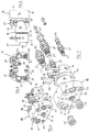
- the attachment is represented by an exemplary coupling part 40, which may be connected to or integrally formed with the attachment in any convenient manner.
- the coupling part 40 is bolted onto the attachment and to this end includes one or more plates 42 with bolt-receiving apertures 44.
- the coupling part 40 includes first and second spaced apart coupling formations, typically in the form of pins 46, 47. The pins 46, 47 extend across the body 48 of the coupling part 40.
- the body 48 typically comprises first and second spaced apart plates 50, 52, with the pins 46, 47 extending transversely between the plates 50, 52 and being fixed to the plates 50, 52 in any convenient manner.
- the coupler 10 is able to engage with attachments that have different spacings between the pins, as is described in more detail hereinafter.
- the coupler 10 has a body 14 typically comprising two spaced-apart body parts typically in the form of side plates 15.
- the body 14 is shaped to define pin-receiving apertures 16 and 17 by which the coupler may be connected to the end of the arm.
- the coupler 10 is able to pivot with respect to the arm about the axis of the one of the apertures 16.
- a hydraulic mechanism, or other power operated mechanism (not shown), is provided, typically in association with a mechanical linkage, to pivot the coupler 10 with respect to the arm.
- the mechanical linkage is usually connected between the arm and the other aperture 17.
- other means for coupling to the arm of an excavator or other machine may be provided.
- the body 14 includes first and second spaced apart coupling formations in the form of first and second pin-receiving recesses 20, 22, typically formed in each side plate 15.
- Each recess 20, 22 is shaped and dimensioned to receive a respective pin 46, 47 of the attachment.
- the recess 20 is typically hook-like in shape and function.
- the recess 22 is advantageously wider than is necessary to receive a single pin 47 in order to accommodate attachments with different pin spacings, i.e. assuming that one pin 46 is located in recess 20, recess 22 is wide enough to receive the other pin 47 for a range of spacings between the pins 46, 47.
- the coupler 10 can therefore accommodate attachments having a range of pin spacings. Such couplers are commonly referred to as universal couplers.
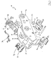
- the coupler 10 also includes a power-operated locking mechanism typically comprising a locking member, in the preferred form of a hook 30, coupled to an actuator 32 typically in the form of a linear actuator such as a hydraulic ram.
- a power-operated locking mechanism typically comprising a locking member, in the preferred form of a hook 30, coupled to an actuator 32 typically in the form of a linear actuator such as a hydraulic ram.
- Other forms of powered actuator could be used (e.g. pneumatic or electrically operated) but hydraulic is convenient because excavators typically have a hydraulic system available at or near the end of the arm.
- the locking hook 30 and ram 32 are provided between the side plates 15.
- the locking hook 30, which may comprise one or more aligned hook elements, may be pivotably mounted on the body 14 at pivot 11 in any convenient manner and is pivotable about an axis that runs substantially perpendicular to the body 14/plates 15.
- the hook 30 is pivotable (or otherwise movable - see below) between an open, or non-locking, state and a locking state by the actuator 32.
- the locking hook 30 In the open state, the locking hook 30 allows the pin 47 to be inserted into or removed from the recess 22. In the locking state, the locking hook 30 prevents the pin 47 from being removed from the recess 22.
- the actual position of the locking member 30 in the locking state will depend on the pin spacing of the attachment being engaged.
- at least one spring 33 e.g. a compression spring, may be provided for urging the locking member 30 into its locking state. Conveniently the spring(s) 33 are located around the piston chamber of the actuator 32 and biased to urge the actuator 32 into an extended state.
- the actuator 32 includes a block 35 (sometimes referred to as a cylinder block) located at the butt end of the piston chamber, i.e. the end opposite the piston rod end.
- the block 35 typically includes one or more hydraulic circuit components, e.g. fluid channel(s) and/or valve(s) (typically including a pilot operated check valve).
- the actuator 32 is coupled to the body 14 of the coupler 10 at the block 35, e.g. by pins 37 or other coupling, which allow pivoting movement of the actuator 32 with respect to the body 14 in preferred emnodiments.
- the recess 22 is said to be at the rear of the coupler and the locking member 30 may therefore be referred to as a rear locking member.
- a front locking member 31 may be provided for releasably holding the pin 46 in the front recess 20.
- the front locking member 31, when present, may be operated into and out of a locking state (in which it holds the pin 46 in the recess 20) by any convenient means. For example it may be pushed by pivoting movement of the actuator 32, may be operated by its own actuator (not shown).
- the locking member 30 is movable substantially linearly between the open and locking states by the actuator 32, and to facilitate this may be slidably mounted on the body 14, for example by means of a linear slide mechanism coupling the locking member to the body 14.
- the various components of the coupler 10, which are shown in exploded view in Figure 1 may be assembled using any convenient fixings and couplings as are, for example, shown in Figure 1 .
- Couplers embodying the invention are particularly, but not exclusively, suited for use with power-operated attachments, especially hydraulically operated attachments.
- power-operated, especially hydraulically operated, attachments include buckets, shears, grapples, drills, breakers, pulverisers, cutters, drive units and other tools.
- Some attachments may comprise one or more electrically operated parts as well as, or instead of, any hydraulically operated parts. Alternatively, or in addition, some attachments may be pneumatically operated.
- the coupling part 40 includes a power coupling unit 54 that includes at least one, but typically a plurality of power couplings or power connectors 56.
- the coupling unit 54 is a hydraulic coupling unit 54 that includes at least one, but typically a plurality of, hydraulic couplings 56.
- the coupling unit 54 may include one or more other types of power connector (e.g. electrical connector(s) and/or pneumatic coupling(s)) as well as or instead of hydraulic coupling(s), depending on the type of attachments with which the coupler is intended to be used.
- the hydraulic couplings 56 may comprise any suitable coupling for use in connection of fluid lines, e.g. British Standard Plumbing (BSP) couplings.
- BSP British Standard Plumbing
- one end 55 of each coupling 56 is connected to a fluid line (not shown but typically in the form of a pipe, hose or tube) of the hydraulic system of the attachment, while the other end 57 is exposed for connection to a corresponding coupling provided on the coupler 10, as is described in more detail hereinafter.
- the couplings 56 are carried by a body 58 of the coupling unit 54, the body 58 conveniently comprising a plate.
- the body 58 comprises a respective though-aperture 59 for receiving each coupling 56 such that the end 55 of the coupling 56 is on the reverse side of the body 58, while the other end 57 is on or otherwise exposed by the obverse side 59.
- the coupling unit 54 may be mounted on the coupling part 40 in any convenient manner.
- the body 58 of the coupling unit 54 is mounted on the body 48 of the coupling part by one or more spring-biased connector 60 that allows relative spring-biased movement between the coupling unit 54 and the coupling part 40.
- the connectors 60 hold the coupling unit 54 spaced apart from the body 48 and allow movement of the coupling unit towards the body 48 against the spring-bias.
- the each connector 60 comprises a fixing pin 61 connecting the body 58 of the coupling unit 54 to the body 48 of the coupling part 40, and respective compression spring 62 located around the pin 61 between the bodies 48, 58.
- one or more guides for example in the form of pins 64 or other suitable formation, are provided at the obverse side of the body 58.
- the coupling unit 54 is located at the rear of the coupling part 40 with its obverse side facing forwardly.
- the obverse side of the coupling unit 54 faces upwardly and obliquely with respect to a plane in which the pins 56, 57 lie.
- the illustrated embodiment there are four hydraulic couplings 56 although in alternative embodiments there may be more or fewer.
- the number and arrangement of the couplings 56 may vary to suit the application.
- the illustrated embodiment has four connectors 60, one at each corner of the body 58. Alternatively there may be more or fewer connectors 60 and they may be arranged as suits the application.
- the illustrated embodiment has two guides 64. Alternatively there may be more or fewer guides 64 and they may be arranged as suits the application.
- the coupler 10 has a power coupling unit 66 for releasably coupling with the power coupling unit 54 of the coupling part 40.
- the coupling unit 66 includes at least one, but typically a plurality of power couplings or power connectors 68 corresponding to the couplings/connectors 56 of the coupling unit 54.
- the coupling unit 66 includes at least one, but typically a plurality of, hydraulic couplings 68.
- the couplings 68 may comprise any suitable coupling for use in connection of fluid lines, e.g. British Standard Plumbing (BSP) couplings.
- BSP British Standard Plumbing
- each coupling 68 is connected to a fluid line (not shown but typically in the form of a pipe, hose or tube) of the hydraulic system of the excavator (or other machine to which the coupler 10 is attached), while the other end 67 is exposed for connection to the end 57 of a corresponding hydraulic coupling 56 provided on the hydraulic coupling unit 54 of the coupling part 40.
- a fluid line not shown but typically in the form of a pipe, hose or tube
- the couplings 68 are carried by a body 70 of the coupling unit 66.
- the body 70 may take any convenient form, preferably including an obverse face 71.
- the body 70 comprises a respective though-aperture 72 for receiving each coupling 68 such that the end 65 of the coupling 68 is on the reverse side of the body 70, while the other end 67 is exposed at the obverse face 71.
- one or more guides are provided at the obverse face 71 of the body 70.
- the guides 75 of the unit 66 are cooperable with the guides of the unit 54 to facilitate engagement of the respective units 54, 66.
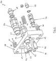
- the coupling unit 66 is coupled to an actuator 74, typically in the form of a linear actuator such as a hydraulic ram.
- a linear actuator such as a hydraulic ram.
- Other forms of powered actuator e.g. a pneumatic or electrically operated actuator
- the actuator 74 is operable to move the coupling unit 66 with respect to the coupler body 14.
- the movement of the coupling unit 66 allows it to be moved into and out of an engaging position in which it engages with the hydraulic coupling unit 56 when the attachment is connected to the coupler 10.
- the coupling unit 66 is connected to the free end of the piston rod (not visible) of the actuator 74 and is movable linearly with respect to the body 14.
- the unit 66 may be connected to the piston rod by any convenient means, e.g. a bolt 77.
- the actuator 74 may be mounted on the coupler body 14 in any convenient manner, typically between the plates 15 using any suitable fixings and/or supports.
- the actuator 74 is located at the rear of the coupler 10 with its obverse face 71 facing forwards.
- the obverse face 71 faces downwardly and obliquely with respect to a plane in which the apertures 20, 22 lie. The location and orientation of the actuator 74 is such that the coupling unit 66 may be moved into and out of engagement with the coupling unit 56 of the coupling part 40.
- hydraulic couplings 68 there are four hydraulic couplings 68 (a respective one for connection to each of the couplings 56) although in alternative embodiments there may be more or fewer.
- the number and arrangement of the couplings 68 may vary to suit the application.
- the hydraulic coupling unit 66 has a respective hydraulic coupling 68 for connecting with a respective hydraulic coupling 56 of the hydraulic coupling unit 54.
- the coupling part 40 may include one or more electrical couplings (which may take any standard form). Any such electrical couplings may be provided on or in the coupling unit 54 (e.g. in the case where the attachment is both hydraulically and electrically powered), or may be provided on or in an electrical coupling unit (e.g. in cases where the attachment is only electrically powered), which may be similar to the coupling unit 54.
- the coupler 10 may include one or more corresponding electrical couplings (which may take any standard form). Any such electrical couplings may be provided on or in the coupling unit 66 (e.g. in the case where the attachment is both hydraulically and electrically powered), or may be provided on or in an electrical coupling unit (e.g.
- the actuator 74 includes a block 76 (sometimes referred to as a cylinder block) located at the butt end of the piston chamber 78, i.e. the end opposite the piston rod end.
- the block 76 typically includes one or more hydraulic circuit components, e.g. fluid channel(s) and/or valve(s) (typically including a pilot operated check valve).
- the actuator 74 is coupled to the body 14 of the coupler 10 at the block 76, e.g. by pins 79 or other fixings.
- the actuator 74 is provided with one or more hydraulic couplings 80 by which it may be connected to one or more hydraulic circuits for operating the actuator 74.
- the hydraulic couplings 80 are provided at the block 76.
- the couplings 80 may comprise any suitable coupling for use in connection of fluid lines, e.g. British Standard Plumbing (BSP) couplings.
- BSP British Standard Plumbing
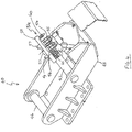
- the hook 30, and if present the hook 31, are in their respective closed state to retain the pins 46, 47 in he recesses 20, 22.
- the hydraulic coupling unit 66 of the coupler 10 is in its engaging position in which it engages with the hydraulic coupling unit 54 of the coupling part 40.
- the obverse face 71 of the coupling unit 66 is brought together with the obverse side of the coupling unit 54 so that the respective hydraulic couplings 68, 56 engage with each other to create a hydraulic connection between the hydraulic system of the excavator and the hydraulic system of the attachment.
- the spring-biased connectors 60 facilitate establishing a fluid-tight connection between the respective hydraulic couplings 68, 56.
- the actuator 32 for the latching hook 30 is connected to the hydraulic system of the excavator in conventional manner (typically via its cylinder block 35).
- the actuator 74 is also connected to the hydraulic system of the excavator, via its cylinder block 76 in the illustrated embodiment, and in particular via hydraulic couplings 80.
- the cylinder block 35 is hydraulically connected to the cylinder block 76 by hydraulic lines 36 to allow hydraulic power to be supplied to the actuator 74.
- the coupler 10 includes a controller for controlling the operation of the actuators 32, 74.
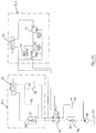
- Figure 10 shows a controller comprising hydraulic circuitry that is suitable for hydraulically connecting the actuators 32, 74 to the hydraulic system of the excavator, or other machine.
- the hydraulic system includes a source 82 of hydraulic fluid (typically oil) and a pump 83 for supplying the hydraulic fluid, under pressure, to the rest of the hydraulic circuitry.
- the hydraulic system includes a hydraulic fluid reservoir, shown in the drawings as tank 84, to which hydraulic fluid is returned.
- the source 83 and tank 84 are provided by the same fluid reservoir.
- each actuator 32, 74 is a double-acting hydraulic ram and incorporated into a respective hydraulic circuit HC1, HC2 for extending and retracting the ram.
- a hydraulic directional control valve 85 is connected between the circuits HC1, HC2 and the source 82 and tank 84 for controlling the flow of hydraulic fluid to and from the circuits HC1, HC2.
- each circuit HC1, HC2 is connected to first and second ports A, B of the valve 85.
- the pump 83 is connected to port P and the tank 84 is connected to port T.
- the valve 85 is operable to effect an extending mode in which hydraulic fluid flows to the circuits via port A and returns to port B, or a retracting mode in which hydraulic fluid flows to the circuits HC1, HC2 via port B and returns via port A.
- the valve 85 may conveniently be a four port/two position directional control valve, wherein in the two positions the connections between the ports P, T and the ports A, B are reversed.
- the valve 85 is preferably electrically controlled, conveniently being a solenoid valve (and may therefore be operable remotely by a user in the cab of the excavator), but may alternatively be controlled by any other means (preferably by remote control means such that it may be operated remotely by a user in the cab of the excavator).
- a check valve 86 is connected between the valve 85 and the pump 83 to prevent fluid flowing from the valve 85 to the pump 83.
- a pilot operated check valve 87 is connected between port A and the extend side of the ram 32 for preventing hydraulic fluid from flowing from the extend side to port A in the extending mode.
- the pilot control line 88 of the valve 87 may be connected to the retract side so that, in the retracting mode, the check valve 87 allows fluid to flow from the extend side to port A.
- hydraulic fluid flows from port A to the extend side of the ram 74 and causes its piston rod to extend. Fluid returns to port B from the retract side of the ram 74.
- hydraulic fluid flows from port B to the retract side of the ram 74 and causes its piston rod to retract. Fluid returns to port A from the extend side of the ram 74.
- circuit HC2 includes a pressure sequence valve 89 in the extend side of the circuit, in particular connected between port A and the extend side of the ram 74.
- the pressure sequence valve 89 is configured so that, in the extending mode, it does not allow hydraulic fluid to flow to the extend side of the ram 74 until the hydraulic fluid pressure supplied to the valve 89 exceeds a pressure threshold value.
- the pressure threshold value may vary depending on the application but in the present example may be approximately 100 bar.
- the valve 89 is a normally-closed valve.
- a check valve 90 may be connected across the sequence valve 89 to allow hydraulic fluid to flow from the extend side to port B bypassing the sequence valve 89.
- circuit HC2 includes a pressure reducing valve 91 in the extend side of the circuit, in particular connected between the sequence valve 89 and the extend side of the ram 74.
- the pressure reducing valve 91 is configured so that, in the extending mode, it reduces or limits the hydraulic fluid pressure flowing to the extend side of the ram 74 to a preset level.
- the preset level may vary depending on the application but in the present example may be approximately 100 bar.
- the valve is a normally-open valve and as such no bypass check valve is required to facilitate the retract mode.
- hydraulic circuits HC1, HC2 may be provided in or on the respective cylinder blocks 35, 76, or elsewhere as is convenient.
- hydraulic lines 36 provide the connections between the ports A, B and the circuit HC2.
- the coupler 10 In order to engage with an attachment, in its open state the coupler 10 is manoeuvred such that the pins 46, 47 are located in the respective recess 20, 22.
- the control valve 85 is operated (conveniently from the cab of the excavator by any conventional remote control means, e.g. comprising one or more user control for causing the coupler to engage or disengage with the attachment) to effect the extending mode in which hydraulic fluid is supplied to the circuits HC1, HC2 via port A.
- ram 32 extends and causes the hook 30 to engage with the pin 47.
- each circuit HC1, HC2 are both connected to port A, the fluid pressure supplied to the sequence valve 89 is correspondingly increased.
- the sequence valve 89 allows hydraulic fluid to flow into the extend side of ram 74, causing ram 74 to extend and moving the coupling unit 66 into the engaged state with the coupling unit 54.
- the coupling unit 66 does not move into engagement with the coupling unit 54 until after the hook 30 has engaged with the pin 47.
- sequence valve 89 serves as activation means that is (indirectly) responsive to engagement of the latch 30 with the pin 47 to cause the coupling unit 66 to move into engagement with the coupling unit 54.
- the coupler may include alternative activation means for controlling its operation such that, when coupling an attachment to the coupler, the hook 30 reaches its locking state before the hydraulic coupling unit 66 is moved into engagement with the hydraulic coupling unit 54.
- the sequence valve 89 may be replaced by a hydraulic switch (not illustrated) that is operable to allow or prevent hydraulic fluid flowing to the extend side of the ram 74 to effect extension of the ram 74.
- the arrangement may be such that the switch is closed (to prevent hydraulic fluid flowing to the extend side of the ram 74) when the hook 30 is in its non-locking state, and open (to allow hydraulic fluid to flow to the extend side of the ram 74) when the hook 30 is in its locked state.
- the switch may be an electrical switch.
- the switch may be of any conventional type, for example it may be a solenoid or relay-operated switch.
- the switch may be operated by any convenient means.
- the switch may be operated by a sensor (not shown), or other detecting means, that is arranged to detect whether or not the hook 30 is in its locking state, and is connected to the switch to operate it accordingly.
- the sensor may be arranged (e.g. suitably located on the coupler) to directly or indirectly detect the location of the hook 30, or the extension of the ram 32, or the pressure in circuit HC1, so that it activates the switch when the hook 30 in in the locking state.
- the sensor may take any conventional form, e.g. a non-contact sensor such as an optical sensor, an electrical field sensor or an acoustic (e.g. ultrasonic sensor), or a contact sensor, e.g.
- the switch may be a mechanically operated switch, such as a plunger switch, lever switch or a limit switch.
- the activation means may comprise a mechanical linkage (not shown) coupled between the coupling unit 66 and the hook 32 and configured to cause the coupling unit 66 to move into engagement with the coupling unit 54 after the hook 32 has reached its locking state.
- the switch may be operated by a timer (e.g. such that the ram 74 is extended a period of time after control valve 85 is activated to extend the hook 30 to allow time for the hook 30 to reach its locking state).
- the hydraulic fluid pressure in the circuits HC1, HC2 is typically relatively high, for example approximately 350 bar, in order that the locking state is securely maintained.
- elevated pressure levels are higher than required to maintain the hydraulic coupling units 54, 66 in the engaged state and may cause damage to any one or more of the ram 74, its mountings and/or the coupling units 66. Therefore it is preferred to provide the pressure reducing valve 91 to reduce the hydraulic fluid pressure supplied to the ram 74 in the extending mode.
- a pressure of approximately 100 bar is sufficient to keep the coupling units 54, 66 in the engaged state.
- the control valve 85 is operated (conveniently from the cab of the excavator by any conventional remote control means) to effect the retracting mode in which hydraulic fluid is supplied to the circuits HC1, HC2 via port B.
- hydraulic fluid is supplied to the respective retract side of each ram 32, 74.
- the spring 33 resists movement of the hook 30 out of the locking state, which causes the ram 74 to retract before the ram 32 retracts.
- the hydraulic coupling unit 66 is moved out of its engaging state before the hook 30 is retracted.
- the arrangement is such that the coupling unit 66 is moved completely clear of the coupling unit 54 before the hook 30 begins to move.
- the retracting force of the ram 32 overcomes the force of the spring 33 and the ram 34 retracts. Hence the hook 30 is moved out of its locking state, allowing the pin 47 to be removed from the recess 22. The attachment may then be removed from the coupler 10 in normal manner.
- the coupler may include alternative delay means for controlling its operation such that, when decoupling an attachment from the coupler, the hook 30 remains in its locking state until after the hydraulic coupling unit 66 is moved out of engagement with the hydraulic coupling unit 54.
- a hydraulic switch (not illustrated) may be incorporated into circuit HC1 that is operable to allow or prevent hydraulic fluid flowing to the retract side of the ram 32, or from the extend side of the ram 32.
- the switch may be an electrical switch.
- the switch may take any conventional form.
- the switch may be operated by a timer (e.g. such that the ram 32 is retracted a period of time after control valve 85 is activated to retract the ram to allow time for the coupling unit 66 to disengage first).
- the switch may be operated by a sensor (not shown), or other detecting means, that is arranged to detect when the coupling unit 66 is disengaged, and is connected to the switch to operate it accordingly.
- the sensor may take any conventional form, e.g. a non-contact sensor such as an optical sensor, an electrical field sensor or an acoustic (e.g. ultrasonic sensor), or a contact sensor, e.g.
- the delay means may comprise a mechanical linkage (not shown) coupled between the coupling unit 66 and the hook 32 and configured to hold the hook 32 in its locking state until after the coupling unit has disengaged from the coupling unit 54.
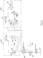
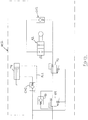
- Figure 11 shows a modification of the circuit of Figure 10 in which a directional control valve 92 is included in the extend side of the circuit HC2 and is operable to selectably allow or prevent hydraulic fluid from being supplied to the extend side of the ram 74.
- the valve 92 is configured to allow fluid to flow to the extend side of the ram 74.
- the valve 92 is configured to prevent fluid from flowing to the extend side of the ram 74, thereby preventing the ram 74 from being extended and the coupling unit 66 from being moved towards its engagement state.
- the valve 92 may conveniently be a two port/two position directional control valve, wherein in the two positions ports A and B are either connected or not connected.
- the valve 92 may be electrically controlled, conveniently being a solenoid valve (and may therefore be operable remotely by a user in the cab of the excavator), but may alternatively be controlled by any other means (optionally such that it may be operated remotely by a user in the cab of the excavator, but alternatively manually by any convenient manual control).
- the valve 92 allows the movement of the coupling unit 66 to be disabled, which helps to prevent it from being damaged in cases where there is no corresponding coupling unit 54 for it to engage with.
- circuits of Figures 10 and 11 include an optional tilt-operated check valve 99, which does not contribute to the present invention and may be omitted.
- the actuator 74 may be an electric actuator operated by an electric circuit.
- alternative actuating means may be provided for moving the coupling unit 66, for example one or more mechanical linkage coupled to the hook 32 or actuator 30.
- the coupler 10 allows hydraulically powered attachments to be mechanically and hydraulically connected to, and disconnected from, the excavator (or other machine) without the operator having to leave the cab, and while reducing the possibility that the hydraulic couplings will be damaged by, for example, misalignments. Moreover, this automatic mechanical and hydraulic connection/disconnection can be achieved for attachments having different spacings between the attachment pins.
- the depressurization system is operable to depressurize hydraulic fluid supply lines 69A, 69B that are connected, in use, to the coupler 10, in particular for supplying hydraulic power to an attachment connected to the coupler.
- depressurization facilitates connection of the couplings 68 of the coupling unit 66 with the corresponding couplings 56 of the coupling unit 54 since this connection can be hindered or prevented if the lines 69A, 69B are pressurized.
- the supply lines 69A, 69B are connected to the coupling unit 66 via a respective one of the hydraulic couplings 68.
- the hydraulic supply lines 69A, 69B typically form part of the hydraulic system of the excavator or other machine to which the coupler 10 is connected, and may be of a type commonly referred to as hammer lines.
- Figure 12 shows the supply lines 69A, 69B connected, in this example by hydraulic fluid lines 63A, 63B, to a depressurization valve device 81 that comprises a respective valve 81 A, 81B for each supply line 69A, 69B.
- the valve device 81 is connected to a hydraulic fluid reservoir, or tank, (not shown in Figure 12 but shown as 93 in Figure 13 ) by one or more hydraulic fluid line 94, as is convenient.
- Figure 13 shows a hydraulic circuit comprising the supply lines 69A, 69B, valve device 81, dump reservoir 93 and interconnecting fluid lines 63A, 63B, 94.
- a respective fluid line 94 and respective reservoir 93 are shown for each valve 81 A, 81B, although a common fluid line 94 and reservoir 93 may alternatively be provided.
- Figure 12 also shows a hydraulic pressure sensitive device, or switch, 73 that is connected hydraulically to the coupler 10, conveniently to the coupling unit 66, by hydraulic line 95.
- the pressure switch 73 is connected to the extend side of actuator 74, but could alternatively be connected to any other convenient location of the coupler's hydraulic circuit, preferably directly or indirectly to any part of the hydraulic supply to the coupler 10 when the actuators 32, 74 are being extended.
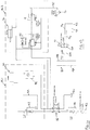
- Figure 14 shows the hydraulic circuit of Figure 10 with the hydraulic pressure switch 73 connected to the hydraulic line that is connected to the extend side of hydraulic actuator 74.
- the depressurization system includes a control device 96 which in preferred embodiments is an electrical switch device.
- the control device 96 controls the operation of the depressurization valve device 81 in response to one or more inputs indicating the state of the coupler 10.
- the control device 96 receives a first input, typically comprising an electrical signal, indicating whether to coupler 10 has been activated to adopt its locking state or its non-locking state.
- the first input is preferably obtained from the coupler 10, conveniently from the electrical part of the solenoid valve 85, preferably by a wired connection 97.
- the first input may be provided wirelessly and/or may be sent from the excavator cab.
- the first input is an electrical power input that is capable of energising, and therefore operating, the valve device 81.
- the control device 96 receives a second input, typically comprising an electrical signal, from the pressure switch 73, conveniently by wired connection 98 but alternatively by a wireless connection.
- the second input signal indicates when the pressure switch 73 detects that the fluid pressure in the relevant part of the coupler hydraulic circuit reaches a threshold value that is indicative of the coupler 10 being in its locked state.
- the threshold value may match the maximum fluid pressure in the relevant part of the hydraulic circuit when the coupler is locked, but preferable is set to a value that is less than the maximum fluid pressure but nevertheless indicative of the coupler being in the locked state, i.e. locked or close to being locked.
- the pressure switch 73 is directly detecting fluid pressure relating to the actuator 74 that controls movement of the coupling unit 66 rather than the hook 32. Nevertheless, such detection is indicative of the locking/non-locking state of the coupler 10.
- the control device 96 provides an output signal to the valve device 81 for controlling the operation of the valve device 81, in particular to open and close the valves 81A, 81B as required.
- the valve device 81 is typically electrically operated and so the output signal from the control device 96 is typically an electrical signal. In preferred embodiments, the output signal is sent to the valve device 81 by a wired connection, but may be sent wirelessly in alternative embodiments.
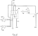
- the valve device 81 is conveniently a solenoid valve device, and in the embodiment shown in Figure 15 comprises a respective solenoid valve 81A, 81B for each of the hydraulic fluid lines 69A, 69B.
- the valve device 81 is operable between a closed state, in which the fluid supply lines 69A, 69B are not connected to the dump reservoir 93 and so fluid pressure is able to build up and/or be maintained in the fluid supply lines 69A, 69B, and an open state in which fluid in the supply lines 69A, 69B is dumped to the dump reservoir 93 via the valve device 81 thereby depressurizing the supply lines 69A, 69B.
- the valve device 81 is closed and the fluid supply lines 69A, 69B are pressurised.
- the corresponding first input signal is sent to the control device 96 (conveniently from solenoid valve 85) to indicate that the coupler 10 is unlocking.
- the control device 96 causes the valve device 81 to open thereby causing the hydraulic lines 69A, 69B to depressurise.
- the control device 96 When the operator activates the coupler to adopt the locking state, the control device 96 causes the valve device 81 to close thereby allowing the supply lines 69A, 69B to pressurise. In preferred embodiments, the control device 96 causes the valve device 81 to close in response to receiving the second input signal indicating that the coupler 10 is in, or substantially in, its locking state. This arrangement prevents accidental pressurization of the lines 69A, 69B. Alternatively, the state of the first input may be used to open and close the valve device 81, in which case the second input and pressure switch 73 are not required..
- the control device 96 receives an electrical power input (at pin 1 in the example of Figure 15 ) and comprises a latch device 96A that is operable to send the received electrical power to the valve device 81 (via pin 4 in the example of Figure 5 ) or not.
- the electrical power input is the first input described above.
- the first input may also be used to operate the latch device 96A to cause it to supply the received electrical power to the valve device 81.
- the first input is also received at pin 2 as a first control signal for causing the latch device 96A to connected pin 1 to pin 4 thereby supplying the power to the valve device 81 to cause it to open.
- the latch device 96A is operated to energise, and therefore open, the valve device 81.
- the latch device 96A is configured to receive a second control signal (at pin 6 in the example of Figure 15 ) for causing the latch device 96A not to send the received power to the valve device 81 (i.e. by connecting its switching element to pin 3 rather than pin 4 in the example of Figure 15 ).
- the second input received from the pressure switch 73 as described above serves as the second control signal for the latching device 96A.
- the first input received by the control device 96 causes the latching device 96A to energise, and therefore open, the valve device 81.
- the latching device 96A maintains the power supply to the valve device 81 (via pins 1 and 4 in Figure 15 ) until the pressure switch 73 sends its signal indicating that the coupler 10 is in, or substantially in, the locking state.
- FIG. 16 there is shown a modified hydraulic circuit HC2' for operating the actuator 74.
- the circuit HC2' is the same as the circuit HC2 of Figure 11 except that optional check valves CV1 and CV2 are provided.
- CV1 is a pilot operated check valve that is connected between port B and the retract side of the ram 74 in order to selectively preventing hydraulic fluid flowing out of the retract side of ram 74.
- the pilot control line PL1 of the valve CV1 is connected to the extend side of ram 74 so that, in the extending mode of the ram 74, PL1 is pressurised and configures CV1 to allow fluid to flow from the retract side of ram 74.
- check valve CV2 is provided and is connected to the extend side of the ram 74, conveniently across (i.e. in parallel with) the valve 92, being configured to allow hydraulic fluid to flow out of the extend side (by passing valve 92 in the illustrated example).
- CV2 allows the ram 74 to be retracted, or pushed back, in the event that any unwanted extension occurs.
- Check valve CV2 may provided integrally with valve 92.
Landscapes
- Engineering & Computer Science (AREA)
- General Engineering & Computer Science (AREA)
- Mechanical Engineering (AREA)
- Mining & Mineral Resources (AREA)
- Civil Engineering (AREA)
- Structural Engineering (AREA)
- Shovels (AREA)
- Operation Control Of Excavators (AREA)
Abstract
Description
- This invention relates to couplers for coupling power operated attachments to the arm of an excavator or other machine.
- Hydraulic couplers for quickly connecting and disconnecting construction attachments from excavating equipment are well known and are sometimes referred to as automatic couplers since they can be operated by an operator from within the cab of an excavator or other machine. International
PCT patent application WO2011/035883 discloses an example of such a coupler. - Some attachments are hydraulically operated in which case, as well as mechanically coupling the attachment to the arm of the excavator, the hydraulic system of the attachment must be connected to the hydraulic system of the excavator. Conventionally, it is the mechanical coupling that is performed automatically, while connection of the hydraulic systems is performed manually, requiring the operator to leave the cab of the excavator. Not only is this slow and inconvenient, but it also increases the operator's exposure to danger as he has to leave the safety of the cab.
- It would be desirable to provide a coupler with an improved hydraulic connection system.
- A first aspect of the invention provides a coupler for coupling an attachment to an excavator or other machine, the coupler comprising:
- a body having a first and second spaced-apart coupling formations for coupling with a respective corresponding coupling formation of said attachment;
- a locking member movable into and out of a locking state in which it is capable of retaining the respective attachment coupling formation in engagement with said first coupling formation;
- a first powered actuator for actuating said locking member into and out of said locking state;
- a first power coupling unit;
- actuating means for moving said power coupling unit with respect to said body into and out of an engaging position in which it is engagable with a corresponding second power coupling unit of said attachment when said attachment is coupled to said excavator or other machine.
- Preferably, the coupler includes activation means configured to cause said actuating means to move said first power coupling unit into said engaging position after said latching member adopts the locking state. The activation means may be responsive to said locking member adopting the locking state to cause said actuating means to move said first power coupling unit into said engaging position. The actuating means may comprise a second powered actuator, and said activation means comprises a component of a circuit for operating said second powered actuator, said component being responsive to said locking member adopting the locking state to cause said second actuator to move said first power coupling unit into said engaging position. The second actuator may comprise a hydraulic actuator and said circuit is a hydraulic circuit, wherein said circuit component comprises a hydraulic sequence valve that is responsive to hydraulic pressure in said hydraulic circuit above a threshold level to cause said second actuator to move said first power coupling unit into said engaging position. The threshold level may correspond to a hydraulic pressure when said locking member is in the locking state.
- Optionally, the circuit component comprises a switch that is operable by means for determining that said locking member adopts the locking state to cause said second actuator to move said first power coupling unit into said engaging position. The switch operating means may comprise a sensor for detecting when said locking member is in the locking state.
- Optionally, the switch operating means comprises a mechanical device arranged for engagement with said locking member, or a component coupled thereto, when said locking member is in the locking state.
- In preferred embodiments, said actuating means comprises a hydraulic actuator connected to a hydraulic operating circuit, and wherein said hydraulic operating circuit includes means, preferably a pressure reducing valve, for reducing hydraulic pressure in said hydraulic operating circuit. The hydraulic operating circuit may comprise a pressure reducing valve connected in series after said sequence valve.
- Optionally, the activation means comprises a timer.
- In some embodiments, said actuating means comprises a second powered actuator, and said activation means comprises a component of a circuit for operating said second powered actuator, said component being responsive to said timer to cause said second actuator to move said first power coupling unit into said engaging position after said latching member adopts the locking state.
- Advantageously, the coupler includes delay means configured to, when decoupling an attachment from the coupler, cause said latching member to remain in its locking state until after the first power coupling unit is moved out of its engaging position. Optionally said delay means comprises at least one spring coupled to said latching means and being biased to urge said latching member into the latching state. Optionally said delay means comprises a component of a circuit for operating said first powered actuator, said component being responsive to said first power coupling unit moving out of said engaging position to cause said first actuator to move said latching member out of said latching state. Said circuit component may comprise a switch that is operable by means for determining that said first power coupling unit is out of said engaging position to cause said first actuator to move said latching member out of said latching state. The switch operating means may comprise a sensor for detecting when said first power coupling unit is out of said engaging position.
- Optionally, the switch operating means comprises a mechanical device arranged for engagement with said first power coupling unit, or a component coupled thereto, when said first power coupling unit moves out of said engaging position. Optionally, said delay means comprises a timer. The delay means may comprise a component of a circuit for operating said first powered actuator, said component being responsive to said timer to cause said first actuator to move said latching member out of said latching state.
- In alternative embodiments, said activation means comprises a mechanical linkage coupled between said latching member and said first power coupling unit.
- In some embodiments, said delay means comprises a mechanical linkage coupled between said latching member and said first power coupling unit.
- In typical embodiments said first power actuator is a hydraulic actuator. Said actuating means typically comprises a hydraulic actuator.
- In preferred embodiments, said first power coupling unit comprises at least one power coupling, typically at least one hydraulic coupling and/or at least one electrical coupling.
- Typical embodiments include control means operable to cause said coupler to couple with said attachment by actuating said latching member into said latching state and moving said first power coupling unit into said engaging position, or to decouple from said attachment by moving said first power coupling unit out of said engaging position and actuating said latching member out of said latching state. The control means may comprise one or more user operable control that is preferably operable from a cab of the excavator or other machine.
- From a second aspect the invention provides a coupling system comprising the coupler of the first aspect, and a coupling part for said attachment, said coupling part including said second power coupling unit. The second power coupling unit may comprise at least one power coupling, typically at least one hydraulic coupling and/or at least one electrical coupling. The coupling part typically includes first and second spaced apart coupling formations, typically comprising first and second pins, for coupling with the first and second coupling formations of said coupler.
- Optionally, the second coupling unit is mounted on the coupling part by one or more spring-biased connector that allows relative spring-biased movement between the second coupling unit and the coupling part, and wherein, preferably, in a rest state the or each connector holds the second coupling unit spaced apart from the coupling part and allows movement of the second coupling unit towards the coupling part against the spring-bias.
- Optionally, said actuating means comprises a hydraulic actuator connected to a hydraulic operating circuit, and wherein said hydraulic operating circuit includes a pilot operated valve connected to the retract side of said hydraulic actuator and configurable to prevent hydraulic fluid flowing from said retract side, a pilot control line coupled between the pilot operated valve and the extend side of said actuator, wherein, in an extend mode of the hydraulic actuator, the pilot control line configures said pilot operated valve to allow fluid to flow from said retract side, the pilot operated valve otherwise being configured to prevent hydraulic fluid flowing from said retract side.
- Optionally, said actuating means comprises a hydraulic actuator connected to a hydraulic operating circuit, and wherein said hydraulic operating circuit includes a check valve connected to the extend side of the actuator and being configured to prevent hydraulic fluid flowing out of said extend side.
- From a third aspect the invention provides a coupling system comprising the coupler of the first aspect of the invention and a depressurization system, wherein said first power coupling unit comprises at least one hydraulic coupling for connection to at least one hydraulic line of a hydraulic system of said excavator or other machine, and wherein said depressurization system comprises:
- a depressurization valve device for selectively connecting said at least one hydraulic line to a hydraulic fluid reservoir in order to dump hydraulic fluid from said at least one hydraulic line to said reservoir; and
- a control device for operating said depressurization valve device, said control device being configured to detect operation of said coupler out of said locking state or into said locking state,
- wherein said control device is configured to, in response to detecting operation of the coupler out of the locking state, operate said depressurization valve device to connect said at least one hydraulic line to said hydraulic fluid reservoir in order to dump hydraulic fluid from said at least one hydraulic line to said reservoir, and in response to detecting operation of the coupler into said locking state, to operate said depressurization valve device to prevent hydraulic fluid being dumped from said at least one hydraulic line to said reservoir.
- In preferred embodiments, said control device is configured to receive a first input indicating operation of said coupler out of said locking state, and to operate said depressurization valve device to connect said at least one hydraulic line to said hydraulic fluid reservoir in response to said first input. Conveniently, said first input is received from said coupler, preferable from a control valve for controlling operation of said coupler into and out of said locking state.
- Optionally, said control device is configured to receive a second input that is indicative of operation of said coupler into said locking state, and to operate said depressurization valve device to disconnect said at least one hydraulic line from said hydraulic fluid reservoir in response to said second input.
- Preferably, the coupling system further includes a pressure sensitive device incorporated into a hydraulic circuit of said coupler and being configured to indicate when the hydraulic pressure in said hydraulic circuit is indicative of the coupler adopting said locked state, and wherein said second input is provided by said pressure sensitive device.
- Optionally, said control device comprises a latch device that is responsive to said first input to operate said depressurization valve device to connect said at least one hydraulic line to said hydraulic fluid reservoir, and is responsive to said second input to operate said depressurization valve device to disconnect said at least one hydraulic line to said hydraulic fluid reservoir.
- Couplers embodying the invention are typically of a type known as quick couplers, more particularly automatic couplers. The invention relates particularly to couplers that are powered, especially hydraulically powered, and advantageously to couplers that are capable of accommodating attachments with different pin spacings.
- Other advantageous aspects of the invention will be apparent to those ordinarily skilled in the art upon review of the following description of a specific embodiment and with reference to the accompanying drawings.
- An embodiment of the invention is now described by way of example and with reference to the accompanying drawings in which:
-
Figure 1 is an exploded perspective view of a coupler embodying the invention; -
Figure 2 is a perspective view of the coupler ofFigure 1 and a coupling part of a hydraulic attachment shown in a non-coupled state; -
Figure 3 is a perspective view of the coupler and coupling part ofFigure 2 shown in a coupled state; -
Figure 4 is an exploded perspective view of the coupling part shown inFigures 2 and3 ; -
Figure 5 is an exploded perspective view of a hydraulic coupling unit included in the coupling part ofFigure 4 ; -
Figure 6 is a perspective view of a hydraulic coupling assembly being part of the coupler ofFigure 1 ; -
Figure 7 is an exploded perspective view of the hydraulic coupling assembly ofFigure 6 ; -
Figure 8 is an end view of the hydraulic coupling assembly ofFigure 6 ; -
Figure 9 is a side view of the hydraulic coupling assembly ofFigure 6 ; -
Figure 10 is a schematic diagram of a hydraulic circuit for use with the coupler ofFigure 1 ; -
Figure 11 is a schematic diagram of an alternative hydraulic circuit for use with the coupler ofFigure 1 ; -
Figure 12 is a perspective view of an optional depressurization system for use with couplers embodying the invention; -
Figure 13 is a hydraulic circuit showing part of the optional depressurization system; -
Figure 14 is a schematic diagram showing the hydraulic circuit ofFigure 10 with an optional pressure switch being part of the preferred depressurization system; -
Figure 15 is a schematic diagram of a preferred electrical control system being part of the optional depressurization system; and -
Figure 16 is a schematic diagram showing part of the hydraulic circuit ofFigure 11 with optional check valves. - Referring now in particular to
Figures 1 to 3 of the drawings there is shown, generally indicated as 10, a respective coupler (also known as a hitch) for connecting an attachment to an arm, or boom, of an excavator (not shown), or other machine. - Couplers embodying the invention are particularly intended for use with attachments having spaced apart pins with which the coupler releasably engages in order to mechanically couple the attachment to the excavator arm. In the drawings, the attachment is represented by an
exemplary coupling part 40, which may be connected to or integrally formed with the attachment in any convenient manner. In the illustrated example it is assumed that thecoupling part 40 is bolted onto the attachment and to this end includes one ormore plates 42 with bolt-receivingapertures 44. Thecoupling part 40 includes first and second spaced apart coupling formations, typically in the form ofpins pins body 48 of thecoupling part 40. Thebody 48 typically comprises first and second spaced apartplates pins plates plates coupler 10 is able to engage with attachments that have different spacings between the pins, as is described in more detail hereinafter. - The
coupler 10 has abody 14 typically comprising two spaced-apart body parts typically in the form ofside plates 15. Thebody 14 is shaped to define pin-receivingapertures apertures side plates 15, the apertures in one side plate being aligned with the apertures in the other. When connected, thecoupler 10 is able to pivot with respect to the arm about the axis of the one of theapertures 16. Usually a hydraulic mechanism, or other power operated mechanism (not shown), is provided, typically in association with a mechanical linkage, to pivot thecoupler 10 with respect to the arm. The mechanical linkage is usually connected between the arm and theother aperture 17. In alternative embodiments, other means for coupling to the arm of an excavator or other machine may be provided. - The
body 14 includes first and second spaced apart coupling formations in the form of first and second pin-receivingrecesses side plate 15. Eachrecess respective pin recesses recess 20 is typically hook-like in shape and function. Therecess 22 is advantageously wider than is necessary to receive asingle pin 47 in order to accommodate attachments with different pin spacings, i.e. assuming that onepin 46 is located inrecess 20,recess 22 is wide enough to receive theother pin 47 for a range of spacings between thepins coupler 10 can therefore accommodate attachments having a range of pin spacings. Such couplers are commonly referred to as universal couplers. - The
coupler 10 also includes a power-operated locking mechanism typically comprising a locking member, in the preferred form of ahook 30, coupled to anactuator 32 typically in the form of a linear actuator such as a hydraulic ram. Other forms of powered actuator could be used (e.g. pneumatic or electrically operated) but hydraulic is convenient because excavators typically have a hydraulic system available at or near the end of the arm. The lockinghook 30 and ram 32 are provided between theside plates 15. The lockinghook 30, which may comprise one or more aligned hook elements, may be pivotably mounted on thebody 14 at pivot 11 in any convenient manner and is pivotable about an axis that runs substantially perpendicular to thebody 14/plates 15. Thehook 30 is pivotable (or otherwise movable - see below) between an open, or non-locking, state and a locking state by theactuator 32. In the open state, the lockinghook 30 allows thepin 47 to be inserted into or removed from therecess 22. In the locking state, the lockinghook 30 prevents thepin 47 from being removed from therecess 22. The actual position of the lockingmember 30 in the locking state will depend on the pin spacing of the attachment being engaged. In preferred embodiments, at least onespring 33, e.g. a compression spring, may be provided for urging the lockingmember 30 into its locking state. Conveniently the spring(s) 33 are located around the piston chamber of theactuator 32 and biased to urge theactuator 32 into an extended state. - In typical embodiments, the
actuator 32 includes a block 35 (sometimes referred to as a cylinder block) located at the butt end of the piston chamber, i.e. the end opposite the piston rod end. Theblock 35 typically includes one or more hydraulic circuit components, e.g. fluid channel(s) and/or valve(s) (typically including a pilot operated check valve). Conveniently, theactuator 32 is coupled to thebody 14 of thecoupler 10 at theblock 35, e.g. bypins 37 or other coupling, which allow pivoting movement of theactuator 32 with respect to thebody 14 in preferred emnodiments. - Conventionally, the
recess 22 is said to be at the rear of the coupler and the lockingmember 30 may therefore be referred to as a rear locking member. Optionally, afront locking member 31 may be provided for releasably holding thepin 46 in thefront recess 20. Thefront locking member 31, when present, may be operated into and out of a locking state (in which it holds thepin 46 in the recess 20) by any convenient means. For example it may be pushed by pivoting movement of theactuator 32, may be operated by its own actuator (not shown). - Under normal operating conditions when the locking
hook 30 is in its locking state, thepin 46 located inrecess 20 is urged against the rear surface 21 of therecess 20 by the action of the lockinghook 30 on theother pin 47 located in theother recess 22 under the force exerted by theactuator 32. - In alternative embodiments (not illustrated) the locking
member 30 is movable substantially linearly between the open and locking states by theactuator 32, and to facilitate this may be slidably mounted on thebody 14, for example by means of a linear slide mechanism coupling the locking member to thebody 14. - The various components of the
coupler 10, which are shown in exploded view inFigure 1 , may be assembled using any convenient fixings and couplings as are, for example, shown inFigure 1 . - Couplers embodying the invention are particularly, but not exclusively, suited for use with power-operated attachments, especially hydraulically operated attachments. Examples of power-operated, especially hydraulically operated, attachments include buckets, shears, grapples, drills, breakers, pulverisers, cutters, drive units and other tools. Some attachments may comprise one or more electrically operated parts as well as, or instead of, any hydraulically operated parts. Alternatively, or in addition, some attachments may be pneumatically operated.
- The
coupling part 40 includes apower coupling unit 54 that includes at least one, but typically a plurality of power couplings orpower connectors 56. In the illustrated embodiment, thecoupling unit 54 is ahydraulic coupling unit 54 that includes at least one, but typically a plurality of,hydraulic couplings 56. In alternative embodiments, thecoupling unit 54 may include one or more other types of power connector (e.g. electrical connector(s) and/or pneumatic coupling(s)) as well as or instead of hydraulic coupling(s), depending on the type of attachments with which the coupler is intended to be used. - The
hydraulic couplings 56 may comprise any suitable coupling for use in connection of fluid lines, e.g. British Standard Plumbing (BSP) couplings. In use, oneend 55 of eachcoupling 56 is connected to a fluid line (not shown but typically in the form of a pipe, hose or tube) of the hydraulic system of the attachment, while theother end 57 is exposed for connection to a corresponding coupling provided on thecoupler 10, as is described in more detail hereinafter. - The
couplings 56 are carried by abody 58 of thecoupling unit 54, thebody 58 conveniently comprising a plate. In preferred embodiments, thebody 58 comprises a respective though-aperture 59 for receiving eachcoupling 56 such that theend 55 of thecoupling 56 is on the reverse side of thebody 58, while theother end 57 is on or otherwise exposed by theobverse side 59. - The
coupling unit 54 may be mounted on thecoupling part 40 in any convenient manner. In preferred embodiments, thebody 58 of thecoupling unit 54 is mounted on thebody 48 of the coupling part by one or more spring-biasedconnector 60 that allows relative spring-biased movement between thecoupling unit 54 and thecoupling part 40. In a rest state, theconnectors 60 hold thecoupling unit 54 spaced apart from thebody 48 and allow movement of the coupling unit towards thebody 48 against the spring-bias. In the illustrated embodiment, the eachconnector 60 comprises a fixingpin 61 connecting thebody 58 of thecoupling unit 54 to thebody 48 of thecoupling part 40, andrespective compression spring 62 located around thepin 61 between thebodies pins 64 or other suitable formation, are provided at the obverse side of thebody 58. - In preferred embodiments, the
coupling unit 54 is located at the rear of thecoupling part 40 with its obverse side facing forwardly. Preferably, the obverse side of thecoupling unit 54 faces upwardly and obliquely with respect to a plane in which thepins - In the illustrated embodiment there are four
hydraulic couplings 56 although in alternative embodiments there may be more or fewer. The number and arrangement of the couplings 56 (hydraulic or otherwise) may vary to suit the application. The illustrated embodiment has fourconnectors 60, one at each corner of thebody 58. Alternatively there may be more orfewer connectors 60 and they may be arranged as suits the application. The illustrated embodiment has two guides 64. Alternatively there may be more orfewer guides 64 and they may be arranged as suits the application. - The
coupler 10 has apower coupling unit 66 for releasably coupling with thepower coupling unit 54 of thecoupling part 40. To this end, thecoupling unit 66 includes at least one, but typically a plurality of power couplings orpower connectors 68 corresponding to the couplings/connectors 56 of thecoupling unit 54. In the illustrated embodiment, thecoupling unit 66 includes at least one, but typically a plurality of,hydraulic couplings 68. Thecouplings 68 may comprise any suitable coupling for use in connection of fluid lines, e.g. British Standard Plumbing (BSP) couplings. In use, oneend 65 of eachcoupling 68 is connected to a fluid line (not shown but typically in the form of a pipe, hose or tube) of the hydraulic system of the excavator (or other machine to which thecoupler 10 is attached), while theother end 67 is exposed for connection to theend 57 of a correspondinghydraulic coupling 56 provided on thehydraulic coupling unit 54 of thecoupling part 40. - The
couplings 68 are carried by abody 70 of thecoupling unit 66. Thebody 70 may take any convenient form, preferably including anobverse face 71. In preferred embodiments, thebody 70 comprises a respective though-aperture 72 for receiving eachcoupling 68 such that theend 65 of thecoupling 68 is on the reverse side of thebody 70, while theother end 67 is exposed at theobverse face 71. Optionally, one or more guides, for example in the form ofsockets 75 or other suitable formation, are provided at theobverse face 71 of thebody 70. Theguides 75 of theunit 66 are cooperable with the guides of theunit 54 to facilitate engagement of therespective units - In preferred embodiments, the
coupling unit 66 is coupled to anactuator 74, typically in the form of a linear actuator such as a hydraulic ram. Other forms of powered actuator (e.g. a pneumatic or electrically operated actuator) or other actuating means may alternatively be used. Theactuator 74 is operable to move thecoupling unit 66 with respect to thecoupler body 14. The movement of thecoupling unit 66 allows it to be moved into and out of an engaging position in which it engages with thehydraulic coupling unit 56 when the attachment is connected to thecoupler 10. Conveniently, thecoupling unit 66 is connected to the free end of the piston rod (not visible) of theactuator 74 and is movable linearly with respect to thebody 14. Theunit 66 may be connected to the piston rod by any convenient means, e.g. abolt 77. - The
actuator 74 may be mounted on thecoupler body 14 in any convenient manner, typically between theplates 15 using any suitable fixings and/or supports. In preferred embodiments, theactuator 74 is located at the rear of thecoupler 10 with itsobverse face 71 facing forwards. Preferably, theobverse face 71 faces downwardly and obliquely with respect to a plane in which theapertures actuator 74 is such that thecoupling unit 66 may be moved into and out of engagement with thecoupling unit 56 of thecoupling part 40. - In the illustrated embodiment there are four hydraulic couplings 68 (a respective one for connection to each of the couplings 56) although in alternative embodiments there may be more or fewer. The number and arrangement of the
couplings 68 may vary to suit the application. More generally, thehydraulic coupling unit 66 has a respectivehydraulic coupling 68 for connecting with a respectivehydraulic coupling 56 of thehydraulic coupling unit 54. - In alternative embodiments (not illustrated) the
coupling part 40 may include one or more electrical couplings (which may take any standard form). Any such electrical couplings may be provided on or in the coupling unit 54 (e.g. in the case where the attachment is both hydraulically and electrically powered), or may be provided on or in an electrical coupling unit (e.g. in cases where the attachment is only electrically powered), which may be similar to thecoupling unit 54. Thecoupler 10 may include one or more corresponding electrical couplings (which may take any standard form). Any such electrical couplings may be provided on or in the coupling unit 66 (e.g. in the case where the attachment is both hydraulically and electrically powered), or may be provided on or in an electrical coupling unit (e.g. in cases where the attachment is only electrically powered), which may be similar to thecoupling unit 66. The arrangement is such that the respective electrical couplings/connectors on thecoupler 10 andcoupling part 40 can be brought into and out of connection with each other in the same or similar manner to that described herein with respect to the hydraulic couplings. - In typical embodiments, the
actuator 74 includes a block 76 (sometimes referred to as a cylinder block) located at the butt end of thepiston chamber 78, i.e. the end opposite the piston rod end. Theblock 76 typically includes one or more hydraulic circuit components, e.g. fluid channel(s) and/or valve(s) (typically including a pilot operated check valve). Conveniently, theactuator 74 is coupled to thebody 14 of thecoupler 10 at theblock 76, e.g. bypins 79 or other fixings. - In preferred embodiments, the
actuator 74 is provided with one or morehydraulic couplings 80 by which it may be connected to one or more hydraulic circuits for operating theactuator 74. Conveniently, thehydraulic couplings 80 are provided at theblock 76. Thecouplings 80 may comprise any suitable coupling for use in connection of fluid lines, e.g. British Standard Plumbing (BSP) couplings. - In use, when the
pins respective recess hook 30, and if present thehook 31, are in their respective closed state to retain thepins hydraulic coupling unit 66 of thecoupler 10 is in its engaging position in which it engages with thehydraulic coupling unit 54 of thecoupling part 40. In the engaged state of theunits obverse face 71 of thecoupling unit 66 is brought together with the obverse side of thecoupling unit 54 so that the respectivehydraulic couplings connectors 60 facilitate establishing a fluid-tight connection between the respectivehydraulic couplings - The
actuator 32 for the latchinghook 30 is connected to the hydraulic system of the excavator in conventional manner (typically via its cylinder block 35). Theactuator 74 is also connected to the hydraulic system of the excavator, via itscylinder block 76 in the illustrated embodiment, and in particular viahydraulic couplings 80. Conveniently, thecylinder block 35 is hydraulically connected to thecylinder block 76 byhydraulic lines 36 to allow hydraulic power to be supplied to theactuator 74. - The
coupler 10 includes a controller for controlling the operation of theactuators Figure 10 shows a controller comprising hydraulic circuitry that is suitable for hydraulically connecting theactuators source 82 of hydraulic fluid (typically oil) and apump 83 for supplying the hydraulic fluid, under pressure, to the rest of the hydraulic circuitry. The hydraulic system includes a hydraulic fluid reservoir, shown in the drawings astank 84, to which hydraulic fluid is returned. Typically, thesource 83 andtank 84 are provided by the same fluid reservoir. In preferred embodiments, each actuator 32, 74 is a double-acting hydraulic ram and incorporated into a respective hydraulic circuit HC1, HC2 for extending and retracting the ram. A hydraulicdirectional control valve 85 is connected between the circuits HC1, HC2 and thesource 82 andtank 84 for controlling the flow of hydraulic fluid to and from the circuits HC1, HC2. In particular, each circuit HC1, HC2 is connected to first and second ports A, B of thevalve 85. Thepump 83 is connected to port P and thetank 84 is connected to port T. Thevalve 85 is operable to effect an extending mode in which hydraulic fluid flows to the circuits via port A and returns to port B, or a retracting mode in which hydraulic fluid flows to the circuits HC1, HC2 via port B and returns via port A. Thevalve 85 may conveniently be a four port/two position directional control valve, wherein in the two positions the connections between the ports P, T and the ports A, B are reversed. Thevalve 85 is preferably electrically controlled, conveniently being a solenoid valve (and may therefore be operable remotely by a user in the cab of the excavator), but may alternatively be controlled by any other means (preferably by remote control means such that it may be operated remotely by a user in the cab of the excavator). - Typically a
check valve 86 is connected between thevalve 85 and thepump 83 to prevent fluid flowing from thevalve 85 to thepump 83. - In the extending mode, hydraulic fluid flows from port A to the extend side of the
ram 32 and causes its piston rod to extend. Fluid returns to port B from the retract side of theram 32. In the retracting mode, hydraulic fluid flows from port B to the retract side of theram 32 and causes its piston rod to retract. Fluid returns to port A from the extend side of theram 32. Optionally a pilot operatedcheck valve 87 is connected between port A and the extend side of theram 32 for preventing hydraulic fluid from flowing from the extend side to port A in the extending mode. Thepilot control line 88 of thevalve 87 may be connected to the retract side so that, in the retracting mode, thecheck valve 87 allows fluid to flow from the extend side to port A. - In the extending mode, hydraulic fluid flows from port A to the extend side of the
ram 74 and causes its piston rod to extend. Fluid returns to port B from the retract side of theram 74. In the retracting mode, hydraulic fluid flows from port B to the retract side of theram 74 and causes its piston rod to retract. Fluid returns to port A from the extend side of theram 74. - Advantageously, circuit HC2 includes a
pressure sequence valve 89 in the extend side of the circuit, in particular connected between port A and the extend side of theram 74. Thepressure sequence valve 89 is configured so that, in the extending mode, it does not allow hydraulic fluid to flow to the extend side of theram 74 until the hydraulic fluid pressure supplied to thevalve 89 exceeds a pressure threshold value. The pressure threshold value may vary depending on the application but in the present example may be approximately 100 bar. In preferred embodiments, thevalve 89 is a normally-closed valve. To facilitate the retracting mode, acheck valve 90 may be connected across thesequence valve 89 to allow hydraulic fluid to flow from the extend side to port B bypassing thesequence valve 89. - In preferred embodiments, circuit HC2 includes a
pressure reducing valve 91 in the extend side of the circuit, in particular connected between thesequence valve 89 and the extend side of theram 74. Thepressure reducing valve 91 is configured so that, in the extending mode, it reduces or limits the hydraulic fluid pressure flowing to the extend side of theram 74 to a preset level. The preset level may vary depending on the application but in the present example may be approximately 100 bar. In preferred embodiments, the valve is a normally-open valve and as such no bypass check valve is required to facilitate the retract mode. - The circuit components of hydraulic circuits HC1, HC2 may be provided in or on the
respective cylinder blocks hydraulic lines 36 provide the connections between the ports A, B and the circuit HC2. - The preferred operation of the
coupler 10 is now described. In order to engage with an attachment, in its open state thecoupler 10 is manoeuvred such that thepins respective recess control valve 85 is operated (conveniently from the cab of the excavator by any conventional remote control means, e.g. comprising one or more user control for causing the coupler to engage or disengage with the attachment) to effect the extending mode in which hydraulic fluid is supplied to the circuits HC1, HC2 via port A. As a result, ram 32 extends and causes thehook 30 to engage with thepin 47. During this extension ofram 32, the fluid pressure supplied to thepressure sequence valve 89 does not exceed its threshold value and so it does not supply pressurised hydraulic fluid to the extend side of theram 74. As a result, theram 74 does not extend and so thehydraulic coupling unit 66 is not moved into engagement with thehydraulic coupling unit 54. After thehook 30 has engaged with thepin 47, hydraulic pressure in circuit HC1, and in particular in its extend side, increases to a level that exceeds the threshold value of thesequence valve 89. Since the circuits HC1, HC2 are interconnected, and in particular since the respective extend side (i.e. the part of the circuit that supplies hydraulic fluid to the extend side of the ram) of each circuit HC1, HC2 are both connected to port A, the fluid pressure supplied to thesequence valve 89 is correspondingly increased. As a result, thesequence valve 89 allows hydraulic fluid to flow into the extend side ofram 74, causingram 74 to extend and moving thecoupling unit 66 into the engaged state with thecoupling unit 54. Hence, thecoupling unit 66 does not move into engagement with thecoupling unit 54 until after thehook 30 has engaged with thepin 47. It is advantageous for thecoupling unit 66 to be moved into engagement with thecoupling unit 54 after thehook 30 has engaged with thepin 47 since this allows correct alignment between theunits units - It will be apparent from the foregoing that the
sequence valve 89 serves as activation means that is (indirectly) responsive to engagement of thelatch 30 with thepin 47 to cause thecoupling unit 66 to move into engagement with thecoupling unit 54. In alternative embodiments, the coupler may include alternative activation means for controlling its operation such that, when coupling an attachment to the coupler, thehook 30 reaches its locking state before thehydraulic coupling unit 66 is moved into engagement with thehydraulic coupling unit 54. For example, thesequence valve 89 may be replaced by a hydraulic switch (not illustrated) that is operable to allow or prevent hydraulic fluid flowing to the extend side of theram 74 to effect extension of theram 74. The arrangement may be such that the switch is closed (to prevent hydraulic fluid flowing to the extend side of the ram 74) when thehook 30 is in its non-locking state, and open (to allow hydraulic fluid to flow to the extend side of the ram 74) when thehook 30 is in its locked state. In alternative embodiments in which movement of thecoupling unit 66 is controlled by an electrical circuit, the switch may be an electrical switch. The switch may be of any conventional type, for example it may be a solenoid or relay-operated switch. - In any event, the switch may be operated by any convenient means. For example, the switch may be operated by a sensor (not shown), or other detecting means, that is arranged to detect whether or not the
hook 30 is in its locking state, and is connected to the switch to operate it accordingly. By way of example, the sensor may be arranged (e.g. suitably located on the coupler) to directly or indirectly detect the location of thehook 30, or the extension of theram 32, or the pressure in circuit HC1, so that it activates the switch when thehook 30 in in the locking state. The sensor may take any conventional form, e.g. a non-contact sensor such as an optical sensor, an electrical field sensor or an acoustic (e.g. ultrasonic sensor), or a contact sensor, e.g. a pressure sensor or a mechanical device that is positioned to be activated (e.g. by pressure or movement) by engagement with the hook itself, or with any other component that moves with the hook, when the hook moves into its locking state (i.e. the switch may be a mechanically operated switch, such as a plunger switch, lever switch or a limit switch). Alternatively still, the activation means may comprise a mechanical linkage (not shown) coupled between thecoupling unit 66 and thehook 32 and configured to cause thecoupling unit 66 to move into engagement with thecoupling unit 54 after thehook 32 has reached its locking state. Alternatively still, the switch may be operated by a timer (e.g. such that theram 74 is extended a period of time aftercontrol valve 85 is activated to extend thehook 30 to allow time for thehook 30 to reach its locking state). - Referring again to
Figure 10 , when thehook 30 is in its locking state, the hydraulic fluid pressure in the circuits HC1, HC2 (and in particular in their respective extend side) is typically relatively high, for example approximately 350 bar, in order that the locking state is securely maintained. Such elevated pressure levels are higher than required to maintain thehydraulic coupling units ram 74, its mountings and/or thecoupling units 66. Therefore it is preferred to provide thepressure reducing valve 91 to reduce the hydraulic fluid pressure supplied to theram 74 in the extending mode. By way of example a pressure of approximately 100 bar is sufficient to keep thecoupling units - In order to release the attachment, the
control valve 85 is operated (conveniently from the cab of the excavator by any conventional remote control means) to effect the retracting mode in which hydraulic fluid is supplied to the circuits HC1, HC2 via port B. As a result, hydraulic fluid is supplied to the respective retract side of eachram spring 33 resists movement of thehook 30 out of the locking state, which causes theram 74 to retract before theram 32 retracts. Accordingly, thehydraulic coupling unit 66 is moved out of its engaging state before thehook 30 is retracted. In preferred embodiments, the arrangement is such that thecoupling unit 66 is moved completely clear of thecoupling unit 54 before thehook 30 begins to move. - After an initial period during which the
ram 32 does not retract, the retracting force of theram 32 overcomes the force of thespring 33 and the ram 34 retracts. Hence thehook 30 is moved out of its locking state, allowing thepin 47 to be removed from therecess 22. The attachment may then be removed from thecoupler 10 in normal manner. - It will be apparent from the foregoing that the
spring 33 serves as delay means for causing thelatch 30 to move out of its locking state after thecoupling unit 66 has disengaged from thecoupling unit 54. In alternative embodiments, the coupler may include alternative delay means for controlling its operation such that, when decoupling an attachment from the coupler, thehook 30 remains in its locking state until after thehydraulic coupling unit 66 is moved out of engagement with thehydraulic coupling unit 54. For example, a hydraulic switch (not illustrated) may be incorporated into circuit HC1 that is operable to allow or prevent hydraulic fluid flowing to the retract side of theram 32, or from the extend side of theram 32. In alternative embodiments in which movement of theram 32 is controlled by an electrical circuit, the switch may be an electrical switch. The switch may take any conventional form. The switch may be operated by a timer (e.g. such that theram 32 is retracted a period of time aftercontrol valve 85 is activated to retract the ram to allow time for thecoupling unit 66 to disengage first). Alternatively, the switch may be operated by a sensor (not shown), or other detecting means, that is arranged to detect when thecoupling unit 66 is disengaged, and is connected to the switch to operate it accordingly. The sensor may take any conventional form, e.g. a non-contact sensor such as an optical sensor, an electrical field sensor or an acoustic (e.g. ultrasonic sensor), or a contact sensor, e.g. a pressure sensor or a mechanical device that is positioned to be activated (e.g. by pressure or movement) by engagement with thecoupling unit 66 itself, or with any other component that moves with thecoupling unit 66, when thecoupling unit 66 moves out of engagement with the coupling unit 54 (i.e. the switch may be a mechanically operated switch, such as a plunger switch, lever switch or a limit switch). Alternatively still, the delay means may comprise a mechanical linkage (not shown) coupled between thecoupling unit 66 and thehook 32 and configured to hold thehook 32 in its locking state until after the coupling unit has disengaged from thecoupling unit 54. - It is advantageous for the
coupling unit 66 to be moved out of engagement with thecoupling unit 54 before thehook 30 has disengaged with thepin 47 since this allows correct alignment between theunits coupling units units -
Figure 11 shows a modification of the circuit ofFigure 10 in which adirectional control valve 92 is included in the extend side of the circuit HC2 and is operable to selectably allow or prevent hydraulic fluid from being supplied to the extend side of theram 74. During operation of thecoupler 10 as described above, thevalve 92 is configured to allow fluid to flow to the extend side of theram 74. However, in cases where the attachment does not require hydraulic power, thevalve 92 is configured to prevent fluid from flowing to the extend side of theram 74, thereby preventing theram 74 from being extended and thecoupling unit 66 from being moved towards its engagement state. - The
valve 92 may conveniently be a two port/two position directional control valve, wherein in the two positions ports A and B are either connected or not connected. Thevalve 92 may be electrically controlled, conveniently being a solenoid valve (and may therefore be operable remotely by a user in the cab of the excavator), but may alternatively be controlled by any other means (optionally such that it may be operated remotely by a user in the cab of the excavator, but alternatively manually by any convenient manual control). Thevalve 92 allows the movement of thecoupling unit 66 to be disabled, which helps to prevent it from being damaged in cases where there is no correspondingcoupling unit 54 for it to engage with. - The circuits of
Figures 10 and11 include an optional tilt-operatedcheck valve 99, which does not contribute to the present invention and may be omitted. - In alternative embodiments, the
actuator 74 may be an electric actuator operated by an electric circuit. Alternatively still, instead of or as well as theactuator 74, alternative actuating means may be provided for moving thecoupling unit 66, for example one or more mechanical linkage coupled to thehook 32 oractuator 30. - It will be apparent from the foregoing that, in preferred embodiments, the
coupler 10 allows hydraulically powered attachments to be mechanically and hydraulically connected to, and disconnected from, the excavator (or other machine) without the operator having to leave the cab, and while reducing the possibility that the hydraulic couplings will be damaged by, for example, misalignments. Moreover, this automatic mechanical and hydraulic connection/disconnection can be achieved for attachments having different spacings between the attachment pins. - Referring now in particular to
Figures 12 to 15 , an optional depressurization system is described and illustrated. The depressurization system is operable to depressurize hydraulicfluid supply lines coupler 10, in particular for supplying hydraulic power to an attachment connected to the coupler. Such depressurization facilitates connection of thecouplings 68 of thecoupling unit 66 with the correspondingcouplings 56 of thecoupling unit 54 since this connection can be hindered or prevented if thelines supply lines coupling unit 66 via a respective one of thehydraulic couplings 68. Thehydraulic supply lines coupler 10 is connected, and may be of a type commonly referred to as hammer lines. -
Figure 12 shows thesupply lines hydraulic fluid lines depressurization valve device 81 that comprises arespective valve supply line valve device 81 is connected to a hydraulic fluid reservoir, or tank, (not shown inFigure 12 but shown as 93 inFigure 13 ) by one or morehydraulic fluid line 94, as is convenient.Figure 13 shows a hydraulic circuit comprising thesupply lines valve device 81,dump reservoir 93 and interconnectingfluid lines Figure 13 arespective fluid line 94 andrespective reservoir 93 are shown for eachvalve common fluid line 94 andreservoir 93 may alternatively be provided. -
Figure 12 also shows a hydraulic pressure sensitive device, or switch, 73 that is connected hydraulically to thecoupler 10, conveniently to thecoupling unit 66, byhydraulic line 95. In the illustrated embodiment, thepressure switch 73 is connected to the extend side ofactuator 74, but could alternatively be connected to any other convenient location of the coupler's hydraulic circuit, preferably directly or indirectly to any part of the hydraulic supply to thecoupler 10 when theactuators Figure 14 shows the hydraulic circuit ofFigure 10 with thehydraulic pressure switch 73 connected to the hydraulic line that is connected to the extend side ofhydraulic actuator 74. - The depressurization system includes a
control device 96 which in preferred embodiments is an electrical switch device. Thecontrol device 96 controls the operation of thedepressurization valve device 81 in response to one or more inputs indicating the state of thecoupler 10. Thecontrol device 96 receives a first input, typically comprising an electrical signal, indicating whether to coupler 10 has been activated to adopt its locking state or its non-locking state. The first input is preferably obtained from thecoupler 10, conveniently from the electrical part of thesolenoid valve 85, preferably by awired connection 97. In alternative embodiments, the first input may be provided wirelessly and/or may be sent from the excavator cab. Preferably, the first input is an electrical power input that is capable of energising, and therefore operating, thevalve device 81. - In preferred embodiments, the
control device 96 receives a second input, typically comprising an electrical signal, from thepressure switch 73, conveniently bywired connection 98 but alternatively by a wireless connection. The second input signal indicates when thepressure switch 73 detects that the fluid pressure in the relevant part of the coupler hydraulic circuit reaches a threshold value that is indicative of thecoupler 10 being in its locked state. The threshold value may match the maximum fluid pressure in the relevant part of the hydraulic circuit when the coupler is locked, but preferable is set to a value that is less than the maximum fluid pressure but nevertheless indicative of the coupler being in the locked state, i.e. locked or close to being locked. It is noted that in the illustrated embodiment where thepressure switch 73 is incorporated into the hydraulic circuit that controls theactuator 74, thepressure switch 73 is directly detecting fluid pressure relating to theactuator 74 that controls movement of thecoupling unit 66 rather than thehook 32. Nevertheless, such detection is indicative of the locking/non-locking state of thecoupler 10. - The
control device 96 provides an output signal to thevalve device 81 for controlling the operation of thevalve device 81, in particular to open and close thevalves valve device 81 is typically electrically operated and so the output signal from thecontrol device 96 is typically an electrical signal. In preferred embodiments, the output signal is sent to thevalve device 81 by a wired connection, but may be sent wirelessly in alternative embodiments. Thevalve device 81 is conveniently a solenoid valve device, and in the embodiment shown inFigure 15 comprises arespective solenoid valve hydraulic fluid lines - The
valve device 81 is operable between a closed state, in which thefluid supply lines dump reservoir 93 and so fluid pressure is able to build up and/or be maintained in thefluid supply lines supply lines dump reservoir 93 via thevalve device 81 thereby depressurizing thesupply lines coupler 10 is in the locking state, thevalve device 81 is closed and thefluid supply lines coupler 10 to adopt the non-locking state, the corresponding first input signal is sent to the control device 96 (conveniently from solenoid valve 85) to indicate that thecoupler 10 is unlocking. In response to the first input signal, thecontrol device 96 causes thevalve device 81 to open thereby causing thehydraulic lines - When the operator activates the coupler to adopt the locking state, the
control device 96 causes thevalve device 81 to close thereby allowing thesupply lines control device 96 causes thevalve device 81 to close in response to receiving the second input signal indicating that thecoupler 10 is in, or substantially in, its locking state. This arrangement prevents accidental pressurization of thelines valve device 81, in which case the second input and pressure switch 73 are not required.. - In preferred embodiments, the
control device 96 receives an electrical power input (atpin 1 in the example ofFigure 15 ) and comprises alatch device 96A that is operable to send the received electrical power to the valve device 81 (viapin 4 in the example ofFigure 5 ) or not. Conveniently the electrical power input is the first input described above. The first input may also be used to operate thelatch device 96A to cause it to supply the received electrical power to thevalve device 81. In the example ofFigure 15 , the first input is also received atpin 2 as a first control signal for causing thelatch device 96A toconnected pin 1 to pin 4 thereby supplying the power to thevalve device 81 to cause it to open. Therefore, when thecontrol device 96 receives the first input as described above, thelatch device 96A is operated to energise, and therefore open, thevalve device 81. Thelatch device 96A is configured to receive a second control signal (at pin 6 in the example ofFigure 15 ) for causing thelatch device 96A not to send the received power to the valve device 81 (i.e. by connecting its switching element to pin 3 rather thanpin 4 in the example ofFigure 15 ). The second input received from thepressure switch 73 as described above serves as the second control signal for thelatching device 96A. Accordingly, when the operator operates thecoupler 10 to adopt its non-locking state, the first input received by thecontrol device 96 causes thelatching device 96A to energise, and therefore open, thevalve device 81. When the operator subsequently operates thecoupler 10 to adopt the locking state, even though the first input atpin 2 is lost, thelatching device 96A maintains the power supply to the valve device 81 (viapins Figure 15 ) until thepressure switch 73 sends its signal indicating that thecoupler 10 is in, or substantially in, the locking state. - Referring now to
Figure 16 , there is shown a modified hydraulic circuit HC2' for operating theactuator 74. The circuit HC2' is the same as the circuit HC2 ofFigure 11 except that optional check valves CV1 and CV2 are provided. CV1 is a pilot operated check valve that is connected between port B and the retract side of theram 74 in order to selectively preventing hydraulic fluid flowing out of the retract side ofram 74. The pilot control line PL1 of the valve CV1 is connected to the extend side ofram 74 so that, in the extending mode of theram 74, PL1 is pressurised and configures CV1 to allow fluid to flow from the retract side ofram 74. However, when theram 74 is not in its extend mode, PL1 is not pressurised and so CV1 prevents fluid flowing out of the retract side ofram 74. Hence the pilot check valve CV1 acts to prevent unwanted extension (sometimes referred to as drift) of theram 74. Alternatively, or in addition, check valve CV2 is provided and is connected to the extend side of theram 74, conveniently across (i.e. in parallel with) thevalve 92, being configured to allow hydraulic fluid to flow out of the extend side (by passingvalve 92 in the illustrated example). CV2 allows theram 74 to be retracted, or pushed back, in the event that any unwanted extension occurs. Check valve CV2 may provided integrally withvalve 92. - The invention is not limited to the embodiment(s) described herein but can be amended or modified without departing from the scope of the present invention.
Claims (15)
- A coupler for coupling an attachment to an excavator or other machine, the coupler comprising:a body having a first and second spaced-apart coupling formations for coupling with a respective corresponding coupling formation of said attachment;a locking member movable into and out of a locking state in which it is capable of retaining the respective attachment coupling formation in engagement with said first coupling formation;a first powered actuator for actuating said locking member into and out of said locking state;a first power coupling unit;actuating means for moving said power coupling unit with respect to said body into and out of an engaging position in which it is engagable with a corresponding second power coupling unit of said attachment when said attachment is coupled to said excavator or other machine.
- The coupler of claim 1, further including activation means configured to cause said actuating means to move said first power coupling unit into said engaging position after said latching member adopts the locking state.
- The coupler of claim 2, wherein said activation means is responsive to said locking member adopting the locking state to cause said actuating means to move said first power coupling unit into said engaging position.
- The coupler of claim 3, wherein said actuating means comprises a second powered actuator, and said activation means comprises a component of a circuit for operating said second powered actuator, said component being responsive to said locking member adopting the locking state to cause said second actuator to move said first power coupling unit into said engaging position, and wherein, optionally, said second actuator is a hydraulic actuator and said circuit is a hydraulic circuit, wherein said circuit component comprises a hydraulic sequence valve that is responsive to hydraulic pressure in said hydraulic circuit above a threshold level to cause said second actuator to move said first power coupling unit into said engaging position, and wherein, preferably, said threshold level corresponds to a hydraulic pressure when said locking member is in the locking state, , or said circuit component optionally comprises a switch that is operable by means for determining that said locking member adopts the locking state to cause said second actuator to move said first power coupling unit into said engaging position, and wherein the switch operating means preferably comprises a sensor for detecting when said locking member is in the locking state, and wherein, optionally, the switch operating means comprises a mechanical device arranged for engagement with said locking member, or a component coupled thereto, when said locking member is in the locking state.
- The coupler of claim 1, wherein said actuating means comprises a hydraulic actuator connected to a hydraulic operating circuit, and wherein said hydraulic operating circuit includes means, preferably a pressure reducing valve, for reducing hydraulic pressure in said hydraulic operating circuit, and wherein, optionally, said second actuator is a hydraulic actuator and said circuit is a hydraulic circuit, wherein said circuit component comprises a hydraulic sequence valve that is responsive to hydraulic pressure in said hydraulic circuit above a threshold level to cause said second actuator to move said first power coupling unit into said engaging position, and wherein, preferably, said threshold level corresponds to a hydraulic pressure when said locking member is in the locking state, and wherein said hydraulic operating circuit comprises a pressure reducing valve connected in series after said sequence valve.
- The coupler of claim 2, wherein activation means comprises a timer, and wherein, preferably, said actuating means comprises a second powered actuator, and said activation means comprises a component of a circuit for operating said second powered actuator, said component being responsive to said timer to cause said second actuator to move said first power coupling unit into said engaging position after said latching member adopts the locking state.
- The coupler of claim 1, further including delay means configured to, when decoupling an attachment from the coupler, cause said latching member to remain in its locking state until after the first power coupling unit is moved out of its engaging position, and wherein, optionally, said delay means comprises:at least one spring coupled to said latching means and being biased to urge said latching member into the latching state; ora component of a circuit for operating said first powered actuator, said component being responsive to said first power coupling unit moving out of said engaging position to cause said first actuator to move said latching member out of said latching state, and wherein, optionally, said circuit component comprises a switch that is operable by means for determining that said first power coupling unit is out of said engaging position to cause said first actuator to move said latching member out of said latching state, and wherein the switch operating means may comprise a sensor for detecting when said first power coupling unit is out of said engaging position, the switch operating means optionally comprising a mechanical device arranged for engagement with said first power coupling unit, or a component coupled thereto, when said first power coupling unit moves out of said engaging position; ora timer, wherein, preferably, said delay means comprises a component of a circuit for operating said first powered actuator, said component being responsive to said timer to cause said first actuator to move said latching member out of said latching state;or a mechanical linkage coupled between said latching member and said first power coupling unit.
- The coupler of claim 2, wherein said activation means comprises a mechanical linkage coupled between said latching member and said first power coupling unit.
- The coupler of any preceding claim, wherein said first powered actuator is a hydraulic actuator, and/or wherein said actuating means comprises a hydraulic actuator.
- The coupler of any preceding claim, wherein said first power coupling unit comprises at least one power coupling, typically at least one hydraulic coupling and/or at least one electrical coupling.
- The coupler of any preceding claim, including control means operable to cause said coupler to couple with said attachment by actuating said latching member into said latching state and moving said first power coupling unit into said engaging position, or to decouple from said attachment by moving said first power coupling unit out of said engaging position and actuating said latching member out of said latching state, and wherein said control means preferably comprises one or more user operable control that is preferably operable from a cab of the excavator or other machine.
- The coupler of any preceding claim, wherein said actuating means comprises a hydraulic actuator connected to a hydraulic operating circuit, and wherein said hydraulic operating circuit includes a pilot operated valve connected to the retract side of said hydraulic actuator and configurable to prevent hydraulic fluid flowing from said retract side, a pilot control line coupled between the pilot operated valve and the extend side of said actuator, wherein, in an extend mode of the hydraulic actuator, the pilot control line configures said pilot operated valve to allow fluid to flow from said retract side, the pilot operated valve otherwise being configured to prevent hydraulic fluid flowing from said retract side, and/or wherein said hydraulic operating circuit includes a check valve connected to the extend side of the actuator and being configured to prevent hydraulic fluid flowing out of said extend side.
- A coupling system comprising the coupler of any preceding claim and a coupling part for said attachment, said coupling part including said second power coupling unit, said second power coupling unit comprising at least one power coupling, typically at least one hydraulic coupling and/or at least one electrical coupling, and wherein, preferably, the second coupling unit is mounted on the coupling part by one or more spring-biased connector that allows relative spring-biased movement between the second coupling unit and the coupling part, and wherein, preferably, in a rest state the or each connector holds the second coupling unit spaced apart from the coupling part and allows movement of the second coupling unit towards the coupling part against the spring-bias.
- A coupling system comprising the coupler of any one of claims 1 to 13, and a depressurization system, wherein said first power coupling unit comprises at least one hydraulic coupling for connection to at least one hydraulic line of a hydraulic system of said excavator or other machine, and wherein said depressurization system comprises:a depressurization valve device for selectively connecting said at least one hydraulic line to a hydraulic fluid reservoir in order to dump hydraulic fluid from said at least one hydraulic line to said reservoir; anda control device for operating said depressurization valve device, said control device being configured to detect operation of said coupler out of said locking state or into said locking state,wherein said control device is configured to, in response to detecting operation of the coupler out of the locking state, operate said depressurization valve device to connect said at least one hydraulic line to said hydraulic fluid reservoir in order to dump hydraulic fluid from said at least one hydraulic line to said reservoir, and in response to detecting operation of the coupler into said locking state, to operate said depressurization valve device to prevent hydraulic fluid being dumped from said at least one hydraulic line to said reservoir.
- The coupling system of claim 14, wherein said control device is configured to receive a first input indicating operation of said coupler out of said locking state, and to operate said depressurization valve device to connect said at least one hydraulic line to said hydraulic fluid reservoir in response to said first input, and wherein, preferably, said first input is received from said coupler, preferably from a control valve for controlling operation of said coupler into and out of said locking state, and/or wherein said control device is configured to receive a second input that is indicative of operation of said coupler into said locking state, and to operate said depressurization valve device to disconnect said at least one hydraulic line from said hydraulic fluid reservoir in response to said second input, and wherein, preferably, the coupling system further includes a pressure sensitive device incorporated into a hydraulic circuit of said coupler and being configured to indicate when the hydraulic pressure in said hydraulic circuit is indicative of the coupler adopting said locked state, and wherein said second input is provided by said pressure sensitive device.
Applications Claiming Priority (1)
| Application Number | Priority Date | Filing Date | Title |
|---|---|---|---|
| GB1900235.1A GB2580380B (en) | 2019-01-08 | 2019-01-08 | Coupler with power connection system |
Publications (3)
| Publication Number | Publication Date |
|---|---|
| EP3680393A1 true EP3680393A1 (en) | 2020-07-15 |
| EP3680393C0 EP3680393C0 (en) | 2024-05-29 |
| EP3680393B1 EP3680393B1 (en) | 2024-05-29 |
Family
ID=65528054
Family Applications (1)
| Application Number | Title | Priority Date | Filing Date |
|---|---|---|---|
| EP20150065.9A Active EP3680393B1 (en) | 2019-01-08 | 2020-01-02 | Coupler with power connection system |
Country Status (4)
| Country | Link |
|---|---|
| US (1) | US11332908B2 (en) |
| EP (1) | EP3680393B1 (en) |
| AU (1) | AU2020200050A1 (en) |
| GB (2) | GB2580380B (en) |
Cited By (2)
| Publication number | Priority date | Publication date | Assignee | Title |
|---|---|---|---|---|
| EP3754118A1 (en) * | 2019-06-17 | 2020-12-23 | Caterpillar Inc. | Coupling assembly and method of hydraulically coupling to a tool |
| CN112854328A (en) * | 2021-04-26 | 2021-05-28 | 徐州徐工挖掘机械有限公司 | Hydraulic drive's excavator accessory quick connector and excavator |
Families Citing this family (12)
| Publication number | Priority date | Publication date | Assignee | Title |
|---|---|---|---|---|
| JP6877528B2 (en) * | 2017-02-28 | 2021-05-26 | 株式会社小松製作所 | Quick coupler circuit and quick coupler attachment / detachment method |
| GB2580109A (en) * | 2018-12-21 | 2020-07-15 | Geith International Ltd | A coupler for coupling an attachment to a dipper arm |
| US11453993B2 (en) * | 2019-06-17 | 2022-09-27 | Caterpillar Inc. | Quick coupler with hydraulic coupling manifold |
| WO2021040515A1 (en) * | 2019-08-23 | 2021-03-04 | Holmatro B.V. | Method for selectively coupling or uncoupling a coupling, and a coupling therefor |
| US11898319B2 (en) * | 2020-07-20 | 2024-02-13 | Jacob A. Petro | Reversible bucket coupler for excavator buckets and method of use |
| KR102304293B1 (en) * | 2020-10-27 | 2021-09-23 | 대모 엔지니어링 주식회사 | Quick Change Device |
| CN112211243A (en) * | 2020-11-02 | 2021-01-12 | 烟台艾迪精密机械股份有限公司 | Hydraulic docking conversion platform and control method thereof |
| US11421395B1 (en) * | 2021-02-09 | 2022-08-23 | Deere & Company | Pin actuation system and method |
| US11619027B1 (en) | 2021-12-21 | 2023-04-04 | Cnh Industrial America Llc | System for connecting different auxiliary implements to a work vehicle for hydraulic control and related auxiliary hydraulic manifold |
| US20230358012A1 (en) | 2022-05-09 | 2023-11-09 | Caterpillar Inc. | Universal hydraulic auxiliary depressurization circuit |
| US20240044099A1 (en) | 2022-08-04 | 2024-02-08 | Caterpillar Inc. | Automated work tool depressurization circuit and method |
| WO2024170679A1 (en) * | 2023-02-15 | 2024-08-22 | 380 Invent Aps | A coupling system |
Citations (8)
| Publication number | Priority date | Publication date | Assignee | Title |
|---|---|---|---|---|
| DE20312899U1 (en) * | 2003-08-21 | 2004-10-28 | NAGLER, Jürgen | Pressurised medium line connection device, e.g. for construction machinery, uses piston with pressure maintaining valve to fix sleigh with coupling half section into locking position |
| EP1566490A1 (en) * | 2004-02-23 | 2005-08-24 | WIMMER, Alois | Arrangement for connecting energy conduits, particularly pressure conduits |
| EP1624116A2 (en) * | 2004-08-02 | 2006-02-08 | Liebherr-Hydraulikbagger GmbH | Hydraulic quick coupler |
| EP2096212A2 (en) * | 2006-03-27 | 2009-09-02 | Baumaschinentechnik Gesellschaft m.b.H. | Tool coupler for construction machine |
| WO2011035883A1 (en) | 2009-09-22 | 2011-03-31 | Ian Hill | Hydraulic coupler with pin retention system for coupling an attachment to a work machine |
| WO2013000926A1 (en) * | 2011-06-28 | 2013-01-03 | Caterpillar Work Tools B.V. | Device to actuate a fluidconnector contamination cover |
| GB2492850A (en) * | 2011-06-09 | 2013-01-16 | Conor Monaghan | Hitch coupler |
| WO2018074937A1 (en) * | 2016-10-21 | 2018-04-26 | Doherty Engineered Attachments Limited | A coupling assembly and an attachment member comprising a coupling member |
Family Cites Families (8)
| Publication number | Priority date | Publication date | Assignee | Title |
|---|---|---|---|---|
| US4208163A (en) * | 1978-01-18 | 1980-06-17 | Renholmens Mekaniska Verkstad Ab | Automatic quick-coupling device |
| US6619319B1 (en) * | 1998-07-29 | 2003-09-16 | Woods Equipment Company | Multi-line fluid connector |
| PL200100B1 (en) * | 2001-03-09 | 2008-12-31 | Liebherr Hydraulikbagger | Quick-release joint |
| AT411838B (en) * | 2001-04-25 | 2004-06-25 | Puehringer Josef Ing Mag | LOADER |
| KR100861487B1 (en) * | 2007-01-23 | 2008-10-02 | 주식회사 에버다임 | Attachment coupler for heavy machinery having an improved automatic safety function |
| US7648305B2 (en) * | 2007-02-08 | 2010-01-19 | Cws Industries (Mfg.) Corp. | Pin grabber coupler |
| US7686563B2 (en) * | 2007-08-23 | 2010-03-30 | 1708828 Ontario Ltd. O/A Horst Welding | Coupling apparatus for releasably coupling hydraulically powered work implements to a work vehicle |
| EP3211143A1 (en) * | 2008-11-03 | 2017-08-30 | Doherty Engineered Attachments Limited | Improvements to work attachment assemblies |
-
2019
- 2019-01-08 GB GB1900235.1A patent/GB2580380B/en active Active
-
2020
- 2020-01-02 EP EP20150065.9A patent/EP3680393B1/en active Active
- 2020-01-02 GB GB2000021.2A patent/GB2581263B/en active Active
- 2020-01-03 AU AU2020200050A patent/AU2020200050A1/en active Pending
- 2020-01-07 US US16/736,598 patent/US11332908B2/en active Active
Patent Citations (8)
| Publication number | Priority date | Publication date | Assignee | Title |
|---|---|---|---|---|
| DE20312899U1 (en) * | 2003-08-21 | 2004-10-28 | NAGLER, Jürgen | Pressurised medium line connection device, e.g. for construction machinery, uses piston with pressure maintaining valve to fix sleigh with coupling half section into locking position |
| EP1566490A1 (en) * | 2004-02-23 | 2005-08-24 | WIMMER, Alois | Arrangement for connecting energy conduits, particularly pressure conduits |
| EP1624116A2 (en) * | 2004-08-02 | 2006-02-08 | Liebherr-Hydraulikbagger GmbH | Hydraulic quick coupler |
| EP2096212A2 (en) * | 2006-03-27 | 2009-09-02 | Baumaschinentechnik Gesellschaft m.b.H. | Tool coupler for construction machine |
| WO2011035883A1 (en) | 2009-09-22 | 2011-03-31 | Ian Hill | Hydraulic coupler with pin retention system for coupling an attachment to a work machine |
| GB2492850A (en) * | 2011-06-09 | 2013-01-16 | Conor Monaghan | Hitch coupler |
| WO2013000926A1 (en) * | 2011-06-28 | 2013-01-03 | Caterpillar Work Tools B.V. | Device to actuate a fluidconnector contamination cover |
| WO2018074937A1 (en) * | 2016-10-21 | 2018-04-26 | Doherty Engineered Attachments Limited | A coupling assembly and an attachment member comprising a coupling member |
Cited By (4)
| Publication number | Priority date | Publication date | Assignee | Title |
|---|---|---|---|---|
| EP3754118A1 (en) * | 2019-06-17 | 2020-12-23 | Caterpillar Inc. | Coupling assembly and method of hydraulically coupling to a tool |
| US11053660B2 (en) | 2019-06-17 | 2021-07-06 | Caterpillar Inc. | Coupling assembly and method of hydraulically coupling to a tool |
| CN112854328A (en) * | 2021-04-26 | 2021-05-28 | 徐州徐工挖掘机械有限公司 | Hydraulic drive's excavator accessory quick connector and excavator |
| CN112854328B (en) * | 2021-04-26 | 2021-07-13 | 徐州徐工挖掘机械有限公司 | Hydraulic drive's excavator accessory quick connector and excavator |
Also Published As
| Publication number | Publication date |
|---|---|
| GB202000021D0 (en) | 2020-02-19 |
| GB201900235D0 (en) | 2019-02-27 |
| GB2580380B (en) | 2021-07-21 |
| GB2581263B (en) | 2021-12-08 |
| US20200217040A1 (en) | 2020-07-09 |
| GB2580380A (en) | 2020-07-22 |
| AU2020200050A1 (en) | 2020-07-23 |
| GB2581263A (en) | 2020-08-12 |
| US11332908B2 (en) | 2022-05-17 |
| EP3680393C0 (en) | 2024-05-29 |
| EP3680393B1 (en) | 2024-05-29 |
Similar Documents
| Publication | Publication Date | Title |
|---|---|---|
| EP3680393B1 (en) | Coupler with power connection system | |
| US7290977B2 (en) | Powered coupling of attachment hydraulics | |
| US5727342A (en) | Hydraulic latch pin assembly for coupling a tool to a construction equipment | |
| US8622645B2 (en) | Coupler with gravity operated safety device | |
| US5546683A (en) | Bucket attachment device with remote controlled retractable pins | |
| US6964122B2 (en) | Coupler for coupling an accessory to a dipper arm and a control system for such a coupler | |
| US20150330053A1 (en) | A coupler | |
| US20110091267A1 (en) | Coupler | |
| IES20070351A2 (en) | A coupler for the working arm(s) of an excavator or the like | |
| EP3036379B1 (en) | Safety coupling mechanism | |
| IES20060247A2 (en) | A quick hitch coupler | |
| EP3754118B1 (en) | Coupling assembly and method of hydraulically coupling to a tool | |
| GB2474573A (en) | Control apparatus for a hydraulic coupler | |
| CA2631107C (en) | Safety device for hydraulic hitch assembly | |
| WO2024170679A1 (en) | A coupling system | |
| US20230417011A1 (en) | Quick-change device having a control device with a mechanically and hydraulically controllable valve | |
| GB2295812A (en) | Coupling Device | |
| IE20060247U1 (en) | A quick hitch coupler | |
| IES84581Y1 (en) | A quick hitch coupler |
Legal Events
| Date | Code | Title | Description |
|---|---|---|---|
| PUAI | Public reference made under article 153(3) epc to a published international application that has entered the european phase |
Free format text: ORIGINAL CODE: 0009012 |
|
| STAA | Information on the status of an ep patent application or granted ep patent |
Free format text: STATUS: THE APPLICATION HAS BEEN PUBLISHED |
|
| AK | Designated contracting states |
Kind code of ref document: A1 Designated state(s): AL AT BE BG CH CY CZ DE DK EE ES FI FR GB GR HR HU IE IS IT LI LT LU LV MC MK MT NL NO PL PT RO RS SE SI SK SM TR |
|
| AX | Request for extension of the european patent |
Extension state: BA ME |
|
| STAA | Information on the status of an ep patent application or granted ep patent |
Free format text: STATUS: REQUEST FOR EXAMINATION WAS MADE |
|
| 17P | Request for examination filed |
Effective date: 20210115 |
|
| RBV | Designated contracting states (corrected) |
Designated state(s): AL AT BE BG CH CY CZ DE DK EE ES FI FR GB GR HR HU IE IS IT LI LT LU LV MC MK MT NL NO PL PT RO RS SE SI SK SM TR |
|
| STAA | Information on the status of an ep patent application or granted ep patent |
Free format text: STATUS: EXAMINATION IS IN PROGRESS |
|
| 17Q | First examination report despatched |
Effective date: 20210907 |
|
| REG | Reference to a national code |
Ref country code: DE Ref legal event code: R079 Ref document number: 602020031490 Country of ref document: DE Free format text: PREVIOUS MAIN CLASS: E02F0003360000 Ipc: F16L0037360000 Ref country code: DE Ref legal event code: R079 Free format text: PREVIOUS MAIN CLASS: E02F0003360000 Ipc: F16L0037360000 |
|
| GRAP | Despatch of communication of intention to grant a patent |
Free format text: ORIGINAL CODE: EPIDOSNIGR1 |
|
| STAA | Information on the status of an ep patent application or granted ep patent |
Free format text: STATUS: GRANT OF PATENT IS INTENDED |
|
| RIC1 | Information provided on ipc code assigned before grant |
Ipc: F16L 37/62 20060101ALI20231205BHEP Ipc: F16L 37/30 20060101ALI20231205BHEP Ipc: E02F 9/22 20060101ALI20231205BHEP Ipc: E02F 3/36 20060101ALI20231205BHEP Ipc: F16L 37/56 20060101ALI20231205BHEP Ipc: F16L 37/36 20060101AFI20231205BHEP |
|
| INTG | Intention to grant announced |
Effective date: 20231222 |
|
| GRAS | Grant fee paid |
Free format text: ORIGINAL CODE: EPIDOSNIGR3 |
|
| GRAA | (expected) grant |
Free format text: ORIGINAL CODE: 0009210 |
|
| STAA | Information on the status of an ep patent application or granted ep patent |
Free format text: STATUS: THE PATENT HAS BEEN GRANTED |
|
| AK | Designated contracting states |
Kind code of ref document: B1 Designated state(s): AL AT BE BG CH CY CZ DE DK EE ES FI FR GR HR HU IE IS IT LI LT LU LV MC MK MT NL NO PL PT RO RS SE SI SK SM TR |
|
| RBV | Designated contracting states (corrected) |
Designated state(s): AL AT BE BG CH CY CZ DE DK EE ES FI FR GR HR HU IE IS IT LI LT LU LV MC MK MT NL NO PL PT RO RS SE SI SK SM TR |
|
| REG | Reference to a national code |
Ref country code: CH Ref legal event code: EP |
|
| REG | Reference to a national code |
Ref country code: IE Ref legal event code: FG4D |
|
| REG | Reference to a national code |
Ref country code: DE Ref legal event code: R096 Ref document number: 602020031490 Country of ref document: DE |
|
| U01 | Request for unitary effect filed |
Effective date: 20240625 |
|
| U07 | Unitary effect registered |
Designated state(s): AT BE BG DE DK EE FI FR IT LT LU LV MT NL PT SE SI Effective date: 20240719 |