EP3680332B1 - Probenvorbereitungssystem und kartusche - Google Patents
Probenvorbereitungssystem und kartusche Download PDFInfo
- Publication number
- EP3680332B1 EP3680332B1 EP19217498.5A EP19217498A EP3680332B1 EP 3680332 B1 EP3680332 B1 EP 3680332B1 EP 19217498 A EP19217498 A EP 19217498A EP 3680332 B1 EP3680332 B1 EP 3680332B1
- Authority
- EP
- European Patent Office
- Prior art keywords
- sample preparation
- cartridge
- pipette tip
- segment
- preparation cartridge
- Prior art date
- Legal status (The legal status is an assumption and is not a legal conclusion. Google has not performed a legal analysis and makes no representation as to the accuracy of the status listed.)
- Active
Links
Images


Classifications
-
- B—PERFORMING OPERATIONS; TRANSPORTING
- B01—PHYSICAL OR CHEMICAL PROCESSES OR APPARATUS IN GENERAL
- B01L—CHEMICAL OR PHYSICAL LABORATORY APPARATUS FOR GENERAL USE
- B01L3/00—Containers or dishes for laboratory use, e.g. laboratory glassware; Droppers
- B01L3/52—Containers specially adapted for storing or dispensing a reagent
- B01L3/527—Containers specially adapted for storing or dispensing a reagent for a plurality of reagents
-
- B—PERFORMING OPERATIONS; TRANSPORTING
- B01—PHYSICAL OR CHEMICAL PROCESSES OR APPARATUS IN GENERAL
- B01L—CHEMICAL OR PHYSICAL LABORATORY APPARATUS FOR GENERAL USE
- B01L3/00—Containers or dishes for laboratory use, e.g. laboratory glassware; Droppers
-
- B—PERFORMING OPERATIONS; TRANSPORTING
- B01—PHYSICAL OR CHEMICAL PROCESSES OR APPARATUS IN GENERAL
- B01L—CHEMICAL OR PHYSICAL LABORATORY APPARATUS FOR GENERAL USE
- B01L3/00—Containers or dishes for laboratory use, e.g. laboratory glassware; Droppers
- B01L3/52—Containers specially adapted for storing or dispensing a reagent
-
- B—PERFORMING OPERATIONS; TRANSPORTING
- B01—PHYSICAL OR CHEMICAL PROCESSES OR APPARATUS IN GENERAL
- B01L—CHEMICAL OR PHYSICAL LABORATORY APPARATUS FOR GENERAL USE
- B01L7/00—Heating or cooling apparatus; Heat insulating devices
- B01L7/52—Heating or cooling apparatus; Heat insulating devices with provision for submitting samples to a predetermined sequence of different temperatures, e.g. for treating nucleic acid samples
-
- C—CHEMISTRY; METALLURGY
- C12—BIOCHEMISTRY; BEER; SPIRITS; WINE; VINEGAR; MICROBIOLOGY; ENZYMOLOGY; MUTATION OR GENETIC ENGINEERING
- C12N—MICROORGANISMS OR ENZYMES; COMPOSITIONS THEREOF; PROPAGATING, PRESERVING, OR MAINTAINING MICROORGANISMS; MUTATION OR GENETIC ENGINEERING; CULTURE MEDIA
- C12N15/00—Mutation or genetic engineering; DNA or RNA concerning genetic engineering, vectors, e.g. plasmids, or their isolation, preparation or purification; Use of hosts therefor
- C12N15/09—Recombinant DNA-technology
- C12N15/10—Processes for the isolation, preparation or purification of DNA or RNA
- C12N15/1003—Extracting or separating nucleic acids from biological samples, e.g. pure separation or isolation methods; Conditions, buffers or apparatuses therefor
-
- G—PHYSICS
- G01—MEASURING; TESTING
- G01N—INVESTIGATING OR ANALYSING MATERIALS BY DETERMINING THEIR CHEMICAL OR PHYSICAL PROPERTIES
- G01N35/00—Automatic analysis not limited to methods or materials provided for in any single one of groups G01N1/00 - G01N33/00; Handling materials therefor
- G01N35/0098—Automatic analysis not limited to methods or materials provided for in any single one of groups G01N1/00 - G01N33/00; Handling materials therefor involving analyte bound to insoluble magnetic carrier, e.g. using magnetic separation
-
- G—PHYSICS
- G01—MEASURING; TESTING
- G01N—INVESTIGATING OR ANALYSING MATERIALS BY DETERMINING THEIR CHEMICAL OR PHYSICAL PROPERTIES
- G01N35/00—Automatic analysis not limited to methods or materials provided for in any single one of groups G01N1/00 - G01N33/00; Handling materials therefor
- G01N35/02—Automatic analysis not limited to methods or materials provided for in any single one of groups G01N1/00 - G01N33/00; Handling materials therefor using a plurality of sample containers moved by a conveyor system past one or more treatment or analysis stations
- G01N35/04—Details of the conveyor system
-
- G—PHYSICS
- G01—MEASURING; TESTING
- G01N—INVESTIGATING OR ANALYSING MATERIALS BY DETERMINING THEIR CHEMICAL OR PHYSICAL PROPERTIES
- G01N35/00—Automatic analysis not limited to methods or materials provided for in any single one of groups G01N1/00 - G01N33/00; Handling materials therefor
- G01N35/10—Devices for transferring samples or any liquids to, in, or from, the analysis apparatus, e.g. suction devices, injection devices
- G01N35/1079—Devices for transferring samples or any liquids to, in, or from, the analysis apparatus, e.g. suction devices, injection devices with means for piercing stoppers or septums
-
- G—PHYSICS
- G01—MEASURING; TESTING
- G01N—INVESTIGATING OR ANALYSING MATERIALS BY DETERMINING THEIR CHEMICAL OR PHYSICAL PROPERTIES
- G01N35/00—Automatic analysis not limited to methods or materials provided for in any single one of groups G01N1/00 - G01N33/00; Handling materials therefor
- G01N35/10—Devices for transferring samples or any liquids to, in, or from, the analysis apparatus, e.g. suction devices, injection devices
- G01N35/1081—Devices for transferring samples or any liquids to, in, or from, the analysis apparatus, e.g. suction devices, injection devices characterised by the means for relatively moving the transfer device and the containers in an horizontal plane
- G01N35/1083—Devices for transferring samples or any liquids to, in, or from, the analysis apparatus, e.g. suction devices, injection devices characterised by the means for relatively moving the transfer device and the containers in an horizontal plane with one horizontal degree of freedom
-
- B—PERFORMING OPERATIONS; TRANSPORTING
- B01—PHYSICAL OR CHEMICAL PROCESSES OR APPARATUS IN GENERAL
- B01L—CHEMICAL OR PHYSICAL LABORATORY APPARATUS FOR GENERAL USE
- B01L2200/00—Solutions for specific problems relating to chemical or physical laboratory apparatus
- B01L2200/04—Exchange or ejection of cartridges, containers or reservoirs
-
- B—PERFORMING OPERATIONS; TRANSPORTING
- B01—PHYSICAL OR CHEMICAL PROCESSES OR APPARATUS IN GENERAL
- B01L—CHEMICAL OR PHYSICAL LABORATORY APPARATUS FOR GENERAL USE
- B01L2200/00—Solutions for specific problems relating to chemical or physical laboratory apparatus
- B01L2200/06—Fluid handling related problems
- B01L2200/0647—Handling flowable solids, e.g. microscopic beads, cells, particles
-
- B—PERFORMING OPERATIONS; TRANSPORTING
- B01—PHYSICAL OR CHEMICAL PROCESSES OR APPARATUS IN GENERAL
- B01L—CHEMICAL OR PHYSICAL LABORATORY APPARATUS FOR GENERAL USE
- B01L2200/00—Solutions for specific problems relating to chemical or physical laboratory apparatus
- B01L2200/06—Fluid handling related problems
- B01L2200/0684—Venting, avoiding backpressure, avoid gas bubbles
-
- B—PERFORMING OPERATIONS; TRANSPORTING
- B01—PHYSICAL OR CHEMICAL PROCESSES OR APPARATUS IN GENERAL
- B01L—CHEMICAL OR PHYSICAL LABORATORY APPARATUS FOR GENERAL USE
- B01L2200/00—Solutions for specific problems relating to chemical or physical laboratory apparatus
- B01L2200/14—Process control and prevention of errors
- B01L2200/141—Preventing contamination, tampering
-
- B—PERFORMING OPERATIONS; TRANSPORTING
- B01—PHYSICAL OR CHEMICAL PROCESSES OR APPARATUS IN GENERAL
- B01L—CHEMICAL OR PHYSICAL LABORATORY APPARATUS FOR GENERAL USE
- B01L2300/00—Additional constructional details
- B01L2300/02—Identification, exchange or storage of information
- B01L2300/021—Identification, e.g. bar codes
- B01L2300/022—Transponder chips
-
- B—PERFORMING OPERATIONS; TRANSPORTING
- B01—PHYSICAL OR CHEMICAL PROCESSES OR APPARATUS IN GENERAL
- B01L—CHEMICAL OR PHYSICAL LABORATORY APPARATUS FOR GENERAL USE
- B01L2300/00—Additional constructional details
- B01L2300/04—Closures and closing means
- B01L2300/041—Connecting closures to device or container
- B01L2300/043—Hinged closures
-
- B—PERFORMING OPERATIONS; TRANSPORTING
- B01—PHYSICAL OR CHEMICAL PROCESSES OR APPARATUS IN GENERAL
- B01L—CHEMICAL OR PHYSICAL LABORATORY APPARATUS FOR GENERAL USE
- B01L2300/00—Additional constructional details
- B01L2300/04—Closures and closing means
- B01L2300/041—Connecting closures to device or container
- B01L2300/044—Connecting closures to device or container pierceable, e.g. films, membranes
-
- B—PERFORMING OPERATIONS; TRANSPORTING
- B01—PHYSICAL OR CHEMICAL PROCESSES OR APPARATUS IN GENERAL
- B01L—CHEMICAL OR PHYSICAL LABORATORY APPARATUS FOR GENERAL USE
- B01L2300/00—Additional constructional details
- B01L2300/06—Auxiliary integrated devices, integrated components
- B01L2300/0672—Integrated piercing tool
-
- B—PERFORMING OPERATIONS; TRANSPORTING
- B01—PHYSICAL OR CHEMICAL PROCESSES OR APPARATUS IN GENERAL
- B01L—CHEMICAL OR PHYSICAL LABORATORY APPARATUS FOR GENERAL USE
- B01L2300/00—Additional constructional details
- B01L2300/06—Auxiliary integrated devices, integrated components
- B01L2300/0681—Filter
-
- B—PERFORMING OPERATIONS; TRANSPORTING
- B01—PHYSICAL OR CHEMICAL PROCESSES OR APPARATUS IN GENERAL
- B01L—CHEMICAL OR PHYSICAL LABORATORY APPARATUS FOR GENERAL USE
- B01L2300/00—Additional constructional details
- B01L2300/08—Geometry, shape and general structure
- B01L2300/0832—Geometry, shape and general structure cylindrical, tube shaped
- B01L2300/0841—Drums
-
- B—PERFORMING OPERATIONS; TRANSPORTING
- B01—PHYSICAL OR CHEMICAL PROCESSES OR APPARATUS IN GENERAL
- B01L—CHEMICAL OR PHYSICAL LABORATORY APPARATUS FOR GENERAL USE
- B01L2300/00—Additional constructional details
- B01L2300/08—Geometry, shape and general structure
- B01L2300/0861—Configuration of multiple channels and/or chambers in a single devices
- B01L2300/0867—Multiple inlets and one sample wells, e.g. mixing, dilution
-
- B—PERFORMING OPERATIONS; TRANSPORTING
- B01—PHYSICAL OR CHEMICAL PROCESSES OR APPARATUS IN GENERAL
- B01L—CHEMICAL OR PHYSICAL LABORATORY APPARATUS FOR GENERAL USE
- B01L2300/00—Additional constructional details
- B01L2300/08—Geometry, shape and general structure
- B01L2300/0887—Laminated structure
-
- B—PERFORMING OPERATIONS; TRANSPORTING
- B01—PHYSICAL OR CHEMICAL PROCESSES OR APPARATUS IN GENERAL
- B01L—CHEMICAL OR PHYSICAL LABORATORY APPARATUS FOR GENERAL USE
- B01L2400/00—Moving or stopping fluids
- B01L2400/04—Moving fluids with specific forces or mechanical means
- B01L2400/0403—Moving fluids with specific forces or mechanical means specific forces
- B01L2400/0415—Moving fluids with specific forces or mechanical means specific forces electrical forces, e.g. electrokinetic
- B01L2400/0421—Moving fluids with specific forces or mechanical means specific forces electrical forces, e.g. electrokinetic electrophoretic flow
-
- B—PERFORMING OPERATIONS; TRANSPORTING
- B01—PHYSICAL OR CHEMICAL PROCESSES OR APPARATUS IN GENERAL
- B01L—CHEMICAL OR PHYSICAL LABORATORY APPARATUS FOR GENERAL USE
- B01L3/00—Containers or dishes for laboratory use, e.g. laboratory glassware; Droppers
- B01L3/02—Burettes; Pipettes
- B01L3/021—Pipettes, i.e. with only one conduit for withdrawing and redistributing liquids
-
- B—PERFORMING OPERATIONS; TRANSPORTING
- B01—PHYSICAL OR CHEMICAL PROCESSES OR APPARATUS IN GENERAL
- B01L—CHEMICAL OR PHYSICAL LABORATORY APPARATUS FOR GENERAL USE
- B01L3/00—Containers or dishes for laboratory use, e.g. laboratory glassware; Droppers
- B01L3/54—Labware with identification means
- B01L3/545—Labware with identification means for laboratory containers
-
- G—PHYSICS
- G01—MEASURING; TESTING
- G01N—INVESTIGATING OR ANALYSING MATERIALS BY DETERMINING THEIR CHEMICAL OR PHYSICAL PROPERTIES
- G01N35/00—Automatic analysis not limited to methods or materials provided for in any single one of groups G01N1/00 - G01N33/00; Handling materials therefor
- G01N2035/00465—Separating and mixing arrangements
-
- G—PHYSICS
- G01—MEASURING; TESTING
- G01N—INVESTIGATING OR ANALYSING MATERIALS BY DETERMINING THEIR CHEMICAL OR PHYSICAL PROPERTIES
- G01N35/00—Automatic analysis not limited to methods or materials provided for in any single one of groups G01N1/00 - G01N33/00; Handling materials therefor
- G01N35/02—Automatic analysis not limited to methods or materials provided for in any single one of groups G01N1/00 - G01N33/00; Handling materials therefor using a plurality of sample containers moved by a conveyor system past one or more treatment or analysis stations
- G01N35/04—Details of the conveyor system
- G01N2035/0401—Sample carriers, cuvettes or reaction vessels
- G01N2035/0403—Sample carriers with closing or sealing means
-
- G—PHYSICS
- G01—MEASURING; TESTING
- G01N—INVESTIGATING OR ANALYSING MATERIALS BY DETERMINING THEIR CHEMICAL OR PHYSICAL PROPERTIES
- G01N35/00—Automatic analysis not limited to methods or materials provided for in any single one of groups G01N1/00 - G01N33/00; Handling materials therefor
- G01N35/02—Automatic analysis not limited to methods or materials provided for in any single one of groups G01N1/00 - G01N33/00; Handling materials therefor using a plurality of sample containers moved by a conveyor system past one or more treatment or analysis stations
- G01N35/04—Details of the conveyor system
- G01N2035/0401—Sample carriers, cuvettes or reaction vessels
- G01N2035/0429—Sample carriers adapted for special purposes
- G01N2035/0436—Sample carriers adapted for special purposes with pre-packaged reagents, i.e. test-packs
-
- G—PHYSICS
- G01—MEASURING; TESTING
- G01N—INVESTIGATING OR ANALYSING MATERIALS BY DETERMINING THEIR CHEMICAL OR PHYSICAL PROPERTIES
- G01N35/00—Automatic analysis not limited to methods or materials provided for in any single one of groups G01N1/00 - G01N33/00; Handling materials therefor
- G01N35/02—Automatic analysis not limited to methods or materials provided for in any single one of groups G01N1/00 - G01N33/00; Handling materials therefor using a plurality of sample containers moved by a conveyor system past one or more treatment or analysis stations
- G01N35/04—Details of the conveyor system
- G01N2035/0439—Rotary sample carriers, i.e. carousels
- G01N2035/0446—Combinations of the above
-
- G—PHYSICS
- G01—MEASURING; TESTING
- G01N—INVESTIGATING OR ANALYSING MATERIALS BY DETERMINING THEIR CHEMICAL OR PHYSICAL PROPERTIES
- G01N35/00—Automatic analysis not limited to methods or materials provided for in any single one of groups G01N1/00 - G01N33/00; Handling materials therefor
- G01N35/00584—Control arrangements for automatic analysers
- G01N35/00722—Communications; Identification
- G01N35/00732—Identification of carriers, materials or components in automatic analysers
Definitions
- the present invention relates to a sample preparation system with a sample preparation cartridge and an analytical reader.
- Point of Care diagnostics market has been growing for several years with the ultimate goal of fulfilling the promise of personalised medicine, or providing the right therapy at the right time for the right patient.
- Many analytical approaches can be applied to samples, such as a molecular diagnostics, chemical analysis, immunoassays, and flow cytometry.
- Current systems typically manipulate samples using a predetermined sequential process of fluid manipulation through chambers according to a specific protocol and as such are not very versatile.
- US2010261179 describes a sample preparation device and analyser, wherein the sample preparation device is in the form of a cartridge that is connected to and operated by the analyser, the cartridge further comprising a carousel with multiple cuvettes that is rotated, and a syringe and pipette that move vertically by actuation of an elevator shaft, said elevator shaft being located on a side of the carousel.
- the present invention seeks to at least partially address some of the above problems.
- a sample preparation cartridge (1) for use with a sample preparation device, the cartridge (1) comprising: a housing (7) defining plural separate segments (31, 32, 33) arranged around a central axis of the housing (7), said segments (31, 32, 33) containing analytes and/or beads (54) or capture filters in use; and a moveable head (14) arranged to rotate around said central axis and lower towards, or raise from, a desired segment (31, 32, 33) when it has been rotated to be positioned above the desired segment (31, 32, 33) in use; wherein the moveable head comprises a pipette tip (6) and the pipette tip (6) comprises a reservoir section (18) capable of supporting fluids, and a nozzle section (6) capable of dispensing and aspirating fluids from the segments (31, 32, 33); wherein the pipette tip (6) is configured to pneumatically connect to a programmable control system for providing positive and negative airflow and the pipette tip
- a disposable sample preparation cartridge and corresponding analytical reader can be provided in a very cost effective and simple manner whilst still ensuring high quality sample preparation for analysis.
- the described two part pipette configuration (comprising a fixed section and a nozzle or tip) provides a highly flexible and compact approach that can be realised in a portable system or a bench top instrument.
- the sample preparation cartridge is easy to fill and seal, as well as being compact and having a low weight. It is also easy for an unskilled user to operate.
- the sample preparation cartridge is arranged to be received into, or onto, an analytical reader constructed simply with few moving components whilst still ensuring high quality sample preparation.
- a sample may be easily and safely transferred selectively between segments (which may also be referred to as chambers), whilst ensuring it remains sealed within the cartridge. This allows a sequence of processing steps to be selected and performed by configuring the series of segments between which a sample is transported.
- the invention can be used to provide an apparatus for analysing a fluid sample by separating and holding a desired analyte, for chemical reaction, from a biological fluid sample.
- a desired analyte for chemical reaction
- the analyte is nucleic acid, but could also be proteins, carbohydrates, bacteria or parasites.
- the system is also capable of processing samples such as blood, saliva, urine, mucus or other bodily fluids as well as solid samples or airborne particles suspended in a liquid.
- samples can be presented to the apparatus in a raw form whilst others may be pre-mixed with chemicals, reagents, diluents or buffers or pre-treated with centrifuge, sonicators, macerators, etc.
- the cartridge When the desired analyte is nucleic acid such as DNA or RNA, the cartridge will separate the nucleic acid from the sample, purify it by washing and then hold it for amplification using PCR. Detection is achieved using optical or electrochemical methods.
- An alternative cartridge comprising a single-piece pipette structure is able to exploit the flexibility, low weight and ease of use benefits, albeit at the cost of a higher profile cartridge.
- Figure 1 depicts a system for analysing fluid samples comprising a removably insertable cartridge 1 and a sample preparation instrument including an analytical reader 3.
- the ornamental design of the cartridge 1 and instrument 3 can be varied without impacting the performance of the system, however features of the current invention disclosed herein enable the cartridge 1 to have a low profile and thus enable the overall combination of cartridge and instrument to be extremely compact.
- the separation of the system into cartridge and instrument enables a multitude of tests, configured within specific cartridges, to be automatically undertaken with a single instrument. These include, but are limited to PCR (thermally cycled), PCR (isothermal), immunoassay, clinical chemistry and lateral flow.
- a sample preparation cartridge 1 is a hollow sealed container having an outer shell 7.
- a closable door 2 in the shell 7 allows access via the user to insert a sample (not shown) into the cartridge 1 in use.
- the cartridge 1 can then be inserted into an analytical reader 3 of a sample preparation device in an opening therein.
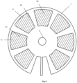
- the sample preparation cartridge 1 is divided into plural segments 31, 32, 33 each providing a chamber 31, 32, 33 which may contain substances for preparation, or components to aid in preparation or reading of the processed sample such as a cuvette 9, or a combination thereof. At least some segments 31, 32, 33 are sealed using a sealing member 11, that may be a foil sheet 11 to ensure that there is no contamination between individual segments 31, 32, 33 during the sample preparation cartridge's 1 handling and/or during its use within the analytical reader 3 of the sample preparation device.
- a sealing member 11 that may be a foil sheet 11 to ensure that there is no contamination between individual segments 31, 32, 33 during the sample preparation cartridge's 1 handling and/or during its use within the analytical reader 3 of the sample preparation device.
- the segments 31, 32, 33 are arranged around a central shaft 5 in a circular fashion around the central axis of the sample preparation cartridge 1.
- the central shaft 5 is arranged so that it can rotate with respect to the outer shell 7 of the sample preparation cartridge 1, and also so that it can slide in the axial direction of the sample preparation cartridge 1 - the axial direction being perpendicular to the plane in which the chambers 31, 32, 33 are circularly arranged.
- it also maintains a seal between the exterior of the cartridge 1 and its interior.
- the shaft 5 has a passageway 16 in connection with pipette arm 14 with an open tip (which may also be referred to as a nozzle) 6 that passes through a filter component 15 and enables fluid access when required to the tip 6 via the shaft 5 to the exterior of the cartridge 1.
- An optional piercing component such as a spike 12 is provided to enable selective piercing of any seal member 11 when required.
- an optional venting shaft with a filtered valve 13 is provided in the shaft 5 to ensure equalization of pressure between the interior of the sample preparation cartridge 1 and the external atmosphere if necessary.
- a receiving component 24 which can receive, in use, a central drive member 4 from the sample preparation device 3 when the sample preparation cartridge 1 has been inserted therein.
- This central drive member 4 has a hollow core which can act to provide fluid connection and access to the passageway component 16 in the central shaft 5.
- the drive member 4 When the drive member 4 is in engagement with the shaft 5 it can also act to move the shaft 5 in the axial direction of the sample preparation cartridge 1, thereby raising and lowering the pipette tip 6 with respect to the individual segments 31, 32, 33 within the shell 7. It can also rotate the shaft 5 around the sample preparation cartridge 1 to move the pipette tip 6 so it is positioned above a selected segment chamber 31, 32, 33.
- tip 6 When in the lowered position tip 6 engages and fluidly seals with the mouth of fixed part of the pipette 8 positioned within a segment 31, 32, 33.
- the sample preparation cartridge 1 is opened by a user and a sample placed within the sample preparation cartridge 1 via the door 2.
- the door 2 is then closed and the sample preparation cartridge 1 is inserted into the analytical reader 3.
- the drive member 4 from the analytical reader 3 is raised to engage with the shaft 5 of the sample preparation cartridge 1.
- the pipette arm 14 can then be rotated to its desired position above a desired segment within the sample preparation cartridge 1.
- the pipette arm 14 can then be lowered, with the spike 12 piercing any sealing member 11 as lowering occurs, to provide a vent hole in the sealing 11 of the segment 31, 32, 33.
- Rotary movement of the pipette tip 6 at this stage will widen the spike hole to ensure that venting occurs.
- the pipette arm 14 and its tip 6 can then engage with any fixed section of pipette 8 in a particular segment 31, 32, 33.
- the tip 6 of the pipette engages with the fixed section of the pipette 8 in the segment to provide a fluid seal and allow any fluid 10 in the desired segment to be drawn up via the tip 6 into the pipette arm 14.
- the fluid can, if desired be drawn into the analytical reader of the sample preparation device 3, or may alternatively be held within the pipette arm 14 whilst it is then raised, rotated and lowered into another desired segment chamber 31, 32, 33 where further processing may occur.
- the other desired segment may contain other analytical substances, or as shown in Figure 2 , may have analytical components in there in which various substances can be mixed and reactions occur if necessary. Filtering using a filter 15 in the pipette can prevent any unwanted components passing into the core of the drive member 4 so that any subsequent sample that is introduced via a sample preparation cartridge 1 will not contaminate the analytical reader 3.
- sample preparation cartridge 1 and analytical reader 3 of the sample preparation instrument can be configured to follow dependent upon the information required in respect of an individual patient.
- a sample can be provided which is then lysed and then mixed with paramagnetic particles to provide magnetic bead separation of target entities which will be described in more detail in reference to the further embodiments of the current invention below.
- Figures 5 to 27 illustrate further examples of the present invention.
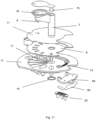
- the cartridge 1 comprises; a lower tray 17, for storing and processing the sample, an upper cover 27, a cuvette 9 and a moveable pipette tip 6.
- a port 26, in the upper cover 27, allows the user to introduce samples into the cartridge 1.
- a door 2 on the upper cover 27 can seal the sample within the cartridge 1 thus preventing contamination of the instrument 3.
- Other configurations such as a membrane seal enabling sample insertion or a removable sample cassette comprised within an insertable bung that functions additionally as a door 2, are possible.
- the use of a port 26 and a door 2 enables the sample to be inserted with minimum risk of contamination or sample fluid loss and at the same time reduces manufacturing complexity.
- the cartridge 1 may be manufactured as an assembly of components which may be individually moulded, milled, manufactured using additive assembly techniques or otherwise manufactured.
- the lower tray 17 contains a plurality of formed segments 31, 32, 33 which provide chambers used to store, contain and process the sample.
- the geometry of each chamber 31, 32, 33 is preferably wedge or cone shaped, with a tapering 'V' shaped floor 34 so as to provide an effective drainage point to extract fluids 10.
- Chambers 31, 32, 33 can be covered by a breakable cover seal 11, such as a foil seal to prevent spillage in transit and increase the shelf life of the reagents.
- the upper cover 27 can carry a machine-readable identification coded tag, such as a 2D bar code 50, RFID chip or other optical, magnetic or near-field wireless interface for conveying data that can be read by the reader.
- the coded tag can convey data identifying the nature of the cartridge 1 and the assays, steps or tests contained therein.
- the coded tag can convey specific instructions to the analytical reader of the device 3. For example a cartridge 1 comprising a new test may be launched on the market after the introduction of the system and the coded tag can be used to advise the instrument 3 of specific temperature cycling requirements. Alternatively or additionally the coded tag may be used to advise the analytical reader of the instrument 3 of time periods, such as settling times during sample aspiration for example.
- the coded tag may further convey traceability and/or tracking information as well as other useful parameters such as expiry date.
- the data and instructions encoded on the coded tag may be used automatically by the instrument 3, and may be done so selectively either with or without user intervention, to deliver a number of enhanced system benefits, safety and efficacy warnings, and/ or usability features.
- the coded tag 50 may incorporate active communication such that status or error messages can be conveyed between cartridge 1 and instrument 3.
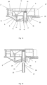
- the cartridge 1 is inserted into the analytical reader of the sample preparation instrument 3 where a central drive shaft 35 of the drive member 4 of the analytical reader 3 is raised to mechanically and pneumatically engage with the movable pipette tip 6 via the shaft 5.
- the mechanical coupling is designed to allow the instrument to selectively move the pipette tip 6, and in this embodiment includes a hexagon shaped drive shaft 35 that locates into a tapering hexagonal hole 24 in the pipette's central shaft 5 so as to provide a means to transfer rotary and vertical motion to accurately control the position of the movable pipette 6.
- the hexagon arrangement allows for ease of engagement; however other shaft profile shapes could be used.
- the drive shaft 35 includes a split-ring 36 that locates in a recess 40 in the pipette central shaft 5 to provide a positive mechanical coupling during vertical movement of the shaft 5.
- the coupling arrangement also includes an O-ring 37, mounted on the drive shaft 35 that pneumatically seals against the inside face of the pipette's central shaft 5 during engagement of the drive shaft 35 into the moveable pipette tip 6.
- the drive shaft 35 may be incorporated within the cartridge 1, and a gear or set of teeth located at its lower edge to interlock with a complementary gear or teeth arrangement located within the instrument 3.
- Alignment sensors may be incorporated into the drive shaft 35, hole 24 or elsewhere that may be used to convey, via an active coded tag, the current status of the cartridge 1 to the analytical reader of the sample preparation instrument 3.
- a movable pipette 6 is used to manipulate fluids within the chambers 31, 32, 33 in the lower tray 17.
- the pipette includes a moveable pipette tip 6, a reservoir 18, connected to a central shaft 5 and is selectively connected to a plurality of fixed pipette nozzle parts 8; one located in each chamber 31, 32, 33.
- the fixed nozzles 8 are positioned so that their tips 71 are at the lowest point of each chamber 31, 32, 33 to enable extraction of the maximum amount of fluid 10 from each chamber 31, 32, 33.
- the geometry of the apparatus allows the instrument 3 to selectively determine the rotary and vertical position of the movable pipette tip 6 relative to the lower tray 17 with segmented chambers 31, 32, 33, containing the reagents.
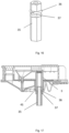
- the movable pipette tip 6 can be aligned, by pre-determined programming of the instrument 3 and in particular the control of the central drive coupling 35, above the desired fixed part of the pipette 8 and lowered into the chamber 31, 32, 33, breaking through a breakable seal 11 (if this has not already been broken).
- the mechanical coupling of the moveable pipette tip 6 and the fixed pipette portion 8, together with the pneumatic connection to the instrument allows fluid to be aspirated or dispensed from or to selected chambers 31, 32, 33 within the lower tray 17 or the reaction chamber 22.
- the lower tray 17 includes an area 51 containing wadding, paper or other means, such as mould texture or pattern, that the movable pipette tip 6 can be lowered onto, to remove excess residue from the pipette tip 6.
- the internal volume of the movable pipette reservoir 18 and the programmable pneumatic system ensures that fluid can be transferred by the movable pipette 6 without the need for liquid to flow through the passageway 16 of the movable pipette's central shaft 5, into the instrument 3.
- a filter 15 between the movable pipette reservoir 18 and pneumatic supply prevents airborne particles from the cartridge 1 contaminating the pneumatic system within the instrument 3.
- the movable pipette tip 6 includes a piercing member such as a spike 12 that pierces the selected chambers breakable seal 11 prior to movable pipette tip 6 engaging with the 'fixed' part of the pipette 8.
- the spike's 12 function is to provide a vent through the breakable seal 11 and as such it is located away from the movable pipette tip 6.
- the vent may be achieved by rotary movement of the movable pipette 6 to form an elongated hole that does not seal around the spike 12.
- the geometry of the spike 12 can be non-circular so as to prevent it sealing against the breakable seal 11 during insertion.
- a filtered breather vent 51 shown here as comprised within the upper cover 27 ensures that the pressure in the cartridge 1 can equalise with ambient during operation. This prevents the risk of the cartridge 1 becoming pressurised and potentially contaminating the instrument 3.
- the filtered breather vent 51 can be held in place, for example, by an identification label 50.
- Mixing of fluids within chambers 31, 32, 33 can be promoted by repeatedly aspirating and dispensing fluid into the pipette tip 6 so as to cause rapid fluid movement within the chamber 31, 32, 33. This yields fast and comprehensive mixing at lower overall system cost than the possible alternatives such as vibrating or agitating the cartridge 1.
- the pipetting arrangement allows for a solution of paramagnetic particles or beads 54 to be used to capture nucleic acid in the sample, and the paramagnetic particles 54 can be subsequently washed to remove unwanted substances whilst retaining the nucleic acid for subsequent treatment or release, according to methods well-known in the art.
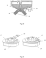
- the arrangement assumes a fixed location and includes two magnets 53, movable between a first position, where their magnetic field attracts magnetic particles to surfaces of the chamber 31, 32, 33, and a second position, where its magnetic field has substantially no effect on the magnetic particles.
- the magnets 53 When in their first position, the magnets 53 are mounted perpendicular to either side of the V shaped chamber 31, 32, 33 to provide a concentrated magnetic field 55 at either side of the chamber and a neutral 'particle free' plane 56 between them that allows fluid, without magnetic particles, to be removed from the lowest point in the chamber 31, 32, 33, via a fixed pipette 8.
- Pipetting clear fluid from the neutral 'particle free' plane 56 allows other areas of the fluid to be bought closer to the rapid clearing zone. This arrangement can significantly increase the rate of bead capture and provides a substantial speed and efficiency benefit over prior art approaches.
- cartridge 1 can be individually configured for specific sample and test types, some of the fluids and substances stored in the chambers 31, 32, 33 in the lower tray 17 are common to several sample types. Cost-efficiencies and shelf-life advantages may be achieved with a generic cartridge 1 that comprises just these common materials. Others might vary for different preparations and these may advantageously be provided in a separate plug-in cartridge 20, inserted into the lower tray 3, prior to use.
- the plug-in cartridge 20 contains a plurality of chambers 55 suitable for storing solid, dried or liquid substances and can be covered by a breakable cover seal 57, such as a foil seal or the like to prevent spillage in transit and increase the shelf life of the reagents.
- the plug-in cartridge 20 also contains a plurality a fixed nozzles 56 that combine with the movable pipette 5.
- the plug-in cartridge 20 can be stored in a separate foil pouch, away from the liquids within the cartridge 1, which provides the benefit of longer shelf life for dried or solid reagents.
- the plug-in cartridge 20 can carry a machine -readable identification coded tag 58, such as a 2D bar code 50, RFID chip or other optical, magnetic or near-field wireless interface for conveying data that can be read by the reader.
- Coded tag 58 can convey data identifying the customised nature of the cartridge 1 incorporating the plug-in cartridge 20 including identification of the assays, steps and / or tests contained within.
- the coded tag can convey specific instructions to the instrument 3.
- a plug-in cartridge 20 comprising materials for a new sample and / or test may be launched on the market after the introduction of the system and the coded tag can be used to advise the instrument 3 of specific requirements, for example temperature cycling requirements.
- the coded tag may be used to advise the instrument of time periods, such as settling times during sample aspiration for example.
- the coded tag may further convey traceability and / or tracking information as well as other useful parameters such as expiry date.
- the data and instructions encoded on the coded tag may be used automatically by the instrument 3, and may be done so selectively either with or without user intervention, to deliver a number of enhanced system benefits, safety and efficacy warnings, and/ or usability features.
- the cartridge geometry allows the plug-in cartridge 20 to be snapped into the lower tray 17, to form part of the chemistry set, accessible by the movable pipette tip 6, required to prepare the sample. Dried or solid reagents are hydrated, during operation, using the aqueous substances stored in the other chambers in the cartridge.
- the analyte can be transferred from a chamber 31, 32, 33, using the movable pipette 6, to a reaction vessel 22 for suitable reaction, such as thermocycling for PCR.
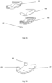
- the reaction vessel 22 is constructed from a moulded section 64, a flexible film 65 and a semi breathable vent 66. Fluid is transferred from a selected chamber 31, 32, 33 and is introduced into the reaction vessel 20 via the movable pipette tip 6. Bubbles in the reaction fluid can affect the analysis readings and the reaction vessel is designed with a geometry that ensures that bubbles are not formed during fill.
- a breather filter allows air to escape from the reaction vessel 22 during the fill process; however the filter is manufactured using hydrophobic material that does not allow fluid through it at the relatively low pressures provided by the instrument 3. In this way, the movable pipette tip 6 is able to produce a positive pressure in the cuvette during the reaction process which helps its thermal contact with the thermal block.
- Measurement of the fluid 10 in the reaction vessel 22 can be achieved via conventional methods such as optical means, electrochemical means, electrophoresis and custom chips.
- the instrument interfaces with the cartridge, either optically, through transparent walls in the reaction chamber or electrically, through electrodes via pads on the cartridge.
- the arrangement allows the chambers 31, 32, 33 to be filled with liquid reagents 10, through the pipette tip, via the fixed part of the pipette 8.
- the cartridge has been described as comprising a pipette structure that has a moving part 6 and fixed parts 8. It should be apparent that this approach yields substantial improvements in form factor, in that the cartridge 1 can achieve a significantly lower profile than if a single-piece, movable pipette were used. However, if space is not a constraint, then the movable pipette 5 can be extended such that the movable tip 21 has sufficient length to be inserted down to the lowest point of each chamber 30, 31, 32, 55 and thus the fixed parts 8 can be eliminated from the system. This might reduce overall cost at the expense of increasing the length of central shaft 5, drive shaft 35 and the overall height of the cartridge 1.
- the arrangement of the movable pipette tip 6, fixed chambers 31, 32, 33 and reagent cartridge 20 allows for a highly flexible and programmable approach that can be used for many types of diagnostic process such as Quantitative or real time PCR (thermally cycled), PCR (isothermal), immunoassay, clinical chemistry, lateral flow, and many others where samples are transferred, mixed, reacted and analysed.
- diagnostic process such as Quantitative or real time PCR (thermally cycled), PCR (isothermal), immunoassay, clinical chemistry, lateral flow, and many others where samples are transferred, mixed, reacted and analysed.
- a user places the sample (blood, fluid, etc.) into the sample preparation cartridge 1 and then places it in the analytical reader 3.
- the reader 3 engages with the sample preparation cartridge 1 (for example mechanically, pneumatically, optically, or thermally) and processes the sample in the cartridge.
- the reader measures the sample preparation cartridge (this could be optical or electrical) and provides a result to the user.
- the sample preparation cartridge 1 is then removed from the reader of the sample preparation device 3 and can be disposed of.
- a compact embodiment has been disclosed wherein the cartridge is inserted in an analytical reader for processing.
- Alternative attachment methods and topologies will be readily apparent to the skilled person, including placing the cartridge onto an analytical instrument, or engaging the analytical reader's drive member into the cartridge using bayonet-like features.
- the present invention provides a simple low cost sample preparation cartridge 1 which is easy for an operator to use through simple insertion.
- the overall depth of the sample preparation cartridge 1 can be reduced to keep it small and compact, low cost and easy to handle.
- filtering in the conduits of the analytical reader 3 it is possible to ensure that there is no contamination of the core analytical reader within a sample preparation device or instrument by individual samples whilst still ensuring simple operation.
Landscapes
- Health & Medical Sciences (AREA)
- Chemical & Material Sciences (AREA)
- Life Sciences & Earth Sciences (AREA)
- General Health & Medical Sciences (AREA)
- Biochemistry (AREA)
- Analytical Chemistry (AREA)
- Physics & Mathematics (AREA)
- Immunology (AREA)
- General Physics & Mathematics (AREA)
- Pathology (AREA)
- Engineering & Computer Science (AREA)
- Genetics & Genomics (AREA)
- Biomedical Technology (AREA)
- Chemical Kinetics & Catalysis (AREA)
- Clinical Laboratory Science (AREA)
- Biotechnology (AREA)
- Zoology (AREA)
- Molecular Biology (AREA)
- Organic Chemistry (AREA)
- Bioinformatics & Cheminformatics (AREA)
- General Engineering & Computer Science (AREA)
- Wood Science & Technology (AREA)
- Microbiology (AREA)
- Plant Pathology (AREA)
- Biophysics (AREA)
- Crystallography & Structural Chemistry (AREA)
- Medicinal Chemistry (AREA)
- Automatic Analysis And Handling Materials Therefor (AREA)
- Sampling And Sample Adjustment (AREA)
- Devices For Use In Laboratory Experiments (AREA)
- Investigating, Analyzing Materials By Fluorescence Or Luminescence (AREA)
Claims (14)
- Probenvorbereitungskartusche (1) zur Verwendung mit einer Probenvorbereitungsvorrichtung, wobei die Kartusche (1) Folgendes umfasst:ein Gehäuse (7), das mehrere separate Segmente (31, 32, 33) definiert, die um eine Mittelachse des Gehäuses (7) angeordnet sind, wobei die Segmente (31, 32, 33) Analyten und/oder Körner (54) oder Auffangfilter in Verwendung enthalten; undeinen beweglichen Kopf (14), der dazu angeordnet ist, um die Mittelachse zu rotieren und sich zu einem gewünschten Segment (31, 32, 33) zu senken, oder von diesem anzuheben, wenn er rotiert worden ist, um über dem gewünschten Segment (31, 32, 33) in Verwendung positioniert zu werden; wobeider bewegliche Kopf eine Pipettenspitze (6) umfasst, die einen Reservoirabschnitt (18), der dazu im Stande ist, Fluida zu halten, und einen Düsenabschnitt (6), der dazu im Stande ist, Fluide von den Segmenten (31, 32, 33) auszugeben und zu belüften, umfasst; wobei die Pipettenspitze (6) dazu ausgelegt ist, pneumatisch an ein programmierbares Steuersystem angeschlossen zu werden, um positiven oder negativen Luftstrom bereitzustellen, und die Pipettenspitze dazu angeordnet ist, in Verwendung Analyten und/oder Körner (54) oder Auffangfilter von einem Segment (31, 32, 33) an ein anderes zu übertragen, um eine Probe zur Analyse vorzubereiten; wobei die Probenvorbereitungskartusche (1) weiter Folgendes umfasst:
einen Schaft (5), der an dem Kopf (14) befestigt ist und auf der Mittelachse positioniert ist, wobei der Schaft (5) dazu angeordnet ist, in Verwendung mit einem Antriebselement (4) in einem analytischen Lesegerät (3) der Probenvorbereitungsvorrichtung einzugreifen, wenn die Probenvorbereitungskartusche (1) darin eingesetzt ist, sodass das Antriebselement (4) den Schaft (5) und den Kopf (14) bewegen kann, wobei der Schaft (5) einen Durchlass (16) umfasst, um strömungstechnische Kommunikation zwischen der Pipettenspitze (6) und dem analytischen Lesegerät (3) zu ermöglichen. - Probenvorbereitungskartusche (1) nach Anspruch 1, wobei mindestens eines der Segmente (31, 32, 33) einen fixierten Abschnitt (8) einer Pipettenkomponente umfasst, und wobei der bewegliche Kopf (14) dazu ausgelegt ist, in Verwendung zwischen einer Position, in der die Pipettenspitze (6) in abgedichtetem Eingriff mit dem fixierten Abschnitt (8) der Pipettenkomponente ist, und einer Position, in der die Pipettenspitze (6) über einem anderen der mehreren Segmente (31, 32, 33) positioniert ist, bewegt zu werden.
- Probenvorbereitungskartusche (1) nach einem vorstehenden Anspruch, wobei die bewegliche Pipettenspitze (6) ein Filter (15) umfasst, um Kontamination zu verringern.
- Probenvorbereitungskartusche (1) nach Anspruch 2 oder 3, wobei mindestens eines der Segmente (31, 32, 33) eine zerbrechbare Fluiddichtung (11) aufweist und der bewegliche Kopf (14) weiter eine Durchstechkomponente (12) umfasst, die dazu angeordnet ist, die zerbrechbare Fluiddichtung (11) zu durchstechen, wenn der Kopf (14) während Eingriffs der Pipettenspitze (6) mit dem fixierten Abschnitt (8) der Pipettenkomponente zu dem jeweiligen Segment (31, 32, 33) bewegt wird, um dem Luftdruck innerhalb des Segments (31, 32, 33) zu ermöglichen, sich während Belüftung und Ausgabe auszugleichen.
- Probenvorbereitungskartusche (1) nach Anspruch 4, wobei der Kopf (14) dazu ausgelegt ist, eine Rotationsbewegung bereitzustellen, so dass die Durchstechkomponente (6) ein längliches Loch erzeugen kann, das nicht um die Durchstechkomponente (6) in Verwendung abdichtet.
- Probenvorbereitungskartusche (1) nach Anspruch 4, wobei die Pipettenspitze (6) nicht kreisförmig ist, um keine Abdichtung mit der zerbrechbaren Dichtung (11) während eines Einsatzes zu erzeugen.
- Probenvorbereitungskartusche (1) nach einem vorstehenden Anspruch, wobei der Schaft (5) in Verwendung weiter einen pneumatischen Eingriff zwischen der Pipettenspitze (6) und dem analytischen Lesegerät (3) bereitstellt, um ein Mittel zum Steuern des Drucks innerhalb der Pipette bereitzustellen.
- Probenvorbereitungskartusche (1) nach einem vorstehenden Anspruch, die weiter einen Bereich (51) umfasst, auf den die bewegliche Pipettenspitze (6) abgesenkt werden kann, um überschüssigen Rest von der Pipettenspitze (6) zu entfernen.
- Probenvorbereitungskartusche (1) nach einem vorstehenden Anspruch, die weiter dazu angeordnet ist, unter Verwendung der Pipettenspitze (6) ein Reaktionsgefäß (22) mit Fluid in Verwendung zur Analyse zu füllen, und weiter ein hydrophobes Filter umfasst, um einen Druck in dem Reaktionsgefäß (22) zu erzeugen, der eine Außenfläche des Reaktionsgefäßes veranlasst, sich zu verformen, wodurch ein guter thermischer Kontakt bereitgestellt wird, wenn es mit einem thermischen Block eines analytischen Lesegeräts eingreift.
- Probenvorbereitungskartusche (1) nach einem vorstehenden Anspruch, wobei das Gehäuse (7) Folgendes umfasst:eine untere Schale (17), die die Vielzahl von separaten Segmenten (31) definiert; undeine obere Abdeckung (27); wobei die untere Schale (17) aus einem einzelnen Kunststoffguss oder separaten Segmenten besteht und wobei die untere Schale (17) eine separate Einsteckkartusche (20) aufweist, die eine Vielzahl von Kammern aufweist, die dazu geeignet sind, feste, getrocknete oder flüssige Substanzen zu lagern.
- Probenvorbereitungskartusche (1) nach einem vorstehenden Anspruch, wobei das Gehäuse (7) eine abdichtbare Tür (2) umfasst, um eine Probe in Verwendung aufzunehmen.
- Probenvorbereitungskartusche (1) nach einem vorstehenden Anspruch, wobei mindestens ein Segment Reagenzien enthält und mindestens ein Segment paramagnetische Körner (54) enthält, wobei das Segment einen sich verjüngenden V-förmigen Boden (34) aufweist, um einen Drainagepunkt bereitzustellen, um Fluida zu extrahieren, und weiter umfassend:
eine Anordnung von Magneten (53), die in Verwendung zu einer Position bewegbar sind, wo ihr magnetisches Feld die paramagnetischen Körner (54) zu Oberflächen des Segments anzieht, wobei die Magnete (53) und das Segment so angeordnet sind, dass sie verwendet werden können, um eine Zone frei von paramagnetischen Körnern (54) für die Pipettenspitze (6) bereitzustellen, um Fluid von dem Segment zu belüften; und dass durch Belüften von Fluid von dem Segment Körner (54) näher zu dem Magnetfeld gebracht werden und die Kornfangrate erhöht wird, wobei das Segment und die Magnete (53) dazu angeordnet sind, die Zone frei von Körnern bei dem niedrigsten Punkt in dem Segment bereitzustellen. - Probenvorbereitungskartusche (1) nach einem vorstehenden Anspruch, die weiter ein codiertes Etikett (58) umfasst, wobei das codierte Etikett eines von entweder einem Strichcode oder einem RFID-Chip umfasst.
- Probenvorbereitungssystem, das die Probenvorbereitungskartusche nach einem der vorstehenden Ansprüche und ein analytisches Lesegerät (3) umfasst, wobei das analytische Lesegerät Mittel zum Aufnehmen der Probenvorbereitungskartusche (1) nach einem der vorstehenden Ansprüche umfasst und Antriebsmittel (4) zum Eingreifen mit der Probenvorbereitungskartusche (1), um den Kopf (14) in Verwendung zu bewegen, umfasst.
Applications Claiming Priority (4)
| Application Number | Priority Date | Filing Date | Title |
|---|---|---|---|
| GBGB1521418.2A GB201521418D0 (en) | 2015-12-04 | 2015-12-04 | Sample preparation system and cartridge |
| GBGB1603938.0A GB201603938D0 (en) | 2016-03-08 | 2016-03-08 | Apparatus for analysing a fluid sample device |
| EP16808788.0A EP3384023B1 (de) | 2015-12-04 | 2016-12-05 | Probenvorbereitungssystem und kartusche |
| PCT/GB2016/053817 WO2017093763A2 (en) | 2015-12-04 | 2016-12-05 | Sample preparation system and cartridge |
Related Parent Applications (2)
| Application Number | Title | Priority Date | Filing Date |
|---|---|---|---|
| EP16808788.0A Division EP3384023B1 (de) | 2015-12-04 | 2016-12-05 | Probenvorbereitungssystem und kartusche |
| EP16808788.0A Division-Into EP3384023B1 (de) | 2015-12-04 | 2016-12-05 | Probenvorbereitungssystem und kartusche |
Publications (3)
| Publication Number | Publication Date |
|---|---|
| EP3680332A1 EP3680332A1 (de) | 2020-07-15 |
| EP3680332C0 EP3680332C0 (de) | 2024-10-09 |
| EP3680332B1 true EP3680332B1 (de) | 2024-10-09 |
Family
ID=57517925
Family Applications (2)
| Application Number | Title | Priority Date | Filing Date |
|---|---|---|---|
| EP19217498.5A Active EP3680332B1 (de) | 2015-12-04 | 2016-12-05 | Probenvorbereitungssystem und kartusche |
| EP16808788.0A Active EP3384023B1 (de) | 2015-12-04 | 2016-12-05 | Probenvorbereitungssystem und kartusche |
Family Applications After (1)
| Application Number | Title | Priority Date | Filing Date |
|---|---|---|---|
| EP16808788.0A Active EP3384023B1 (de) | 2015-12-04 | 2016-12-05 | Probenvorbereitungssystem und kartusche |
Country Status (6)
| Country | Link |
|---|---|
| US (2) | US10857538B2 (de) |
| EP (2) | EP3680332B1 (de) |
| CN (1) | CN108779458B (de) |
| ES (1) | ES2789698T3 (de) |
| GB (1) | GB2556835C (de) |
| WO (1) | WO2017093763A2 (de) |
Families Citing this family (15)
| Publication number | Priority date | Publication date | Assignee | Title |
|---|---|---|---|---|
| US11207674B2 (en) | 2017-08-09 | 2021-12-28 | Biogx, Inc. | Method of customizing a universal reagent cartridge with a lyophilized target-specific reagent |
| EP4051433A4 (de) * | 2019-10-28 | 2022-12-21 | Siemens Healthcare Diagnostics, Inc. | Vibrierende pipettenspitzen und verfahren zur vermeidung von pipettenspitzenhaftreibung |
| EP3832315B1 (de) * | 2019-12-06 | 2025-05-28 | F. Hoffmann-La Roche AG | Pipettiereinheit und pipettierverfahren für geschlossene flüssigkeitsbehälter |
| EP3834939A1 (de) * | 2019-12-12 | 2021-06-16 | TTP plc | Probenvorbereitungssystem |
| BR112022012927A2 (pt) * | 2019-12-30 | 2022-09-06 | Abbott Diagnostics Scarborough Inc | Dispositivo de preparo de amostra e métodos para uso deste |
| JP7340267B2 (ja) * | 2020-04-20 | 2023-09-07 | レオバイオ・カンパニー・リミテッド | 糖化ヘモグロビンの測定装置及び方法 |
| US20230157599A1 (en) * | 2020-04-27 | 2023-05-25 | Innovero Llc | Devices for securely storing bodily fluids and associated systems and methods |
| CN111574584B (zh) * | 2020-05-21 | 2022-03-29 | 中国科学院生物物理研究所 | 全自动蛋白质纯化系统装置及其用途 |
| GB202015911D0 (en) * | 2020-10-07 | 2020-11-18 | Sigenex Inc | Systems and methods for processing a sample |
| GB202016715D0 (en) * | 2020-10-21 | 2020-12-02 | Ttp Plc | Sample analysis cartridge and system |
| WO2022139812A1 (en) * | 2020-12-22 | 2022-06-30 | Hp Health Solutions Inc. | Dual mechanical heating control |
| JP2024507699A (ja) * | 2021-01-29 | 2024-02-21 | アボット・ダイアグノスティックス・スカボロー・インコーポレイテッド | 磁性粒子分離デバイスの緩衝液パック及びキャップの設計 |
| US20230381770A1 (en) * | 2022-05-26 | 2023-11-30 | Syndex Bio Ltd. | Sample Preparation Cartridge and System |
| KR102814100B1 (ko) * | 2022-08-02 | 2025-05-28 | 주식회사 아이젠텍 | 질병의 진단을 위한 올인원 카트리지 및 진단기기 |
| GB2629183A (en) * | 2023-04-20 | 2024-10-23 | Ttp Plc | A modular biological processing cartridge and container |
Family Cites Families (9)
| Publication number | Priority date | Publication date | Assignee | Title |
|---|---|---|---|---|
| DE19643981C2 (de) * | 1996-10-31 | 2001-07-26 | Testo Gmbh & Co | Vorrichtung zum Ermitteln der Konzentration eines Stoffes in einem gasförmigen Medium |
| JP4193566B2 (ja) * | 2003-05-06 | 2008-12-10 | 東ソー株式会社 | 自動分析装置 |
| GB0319671D0 (en) * | 2003-08-21 | 2003-09-24 | Secr Defence | Apparatus for processing a fluid sample |
| GB0704035D0 (en) * | 2007-03-02 | 2007-04-11 | Smiths Detection Watford Ltd | Sample preparation apparatus |
| GB0720264D0 (en) * | 2007-10-17 | 2007-11-28 | Smiths Detection Watford Ltd | Sample preparation devices and analyzers |
| JP5300447B2 (ja) * | 2008-12-04 | 2013-09-25 | ベックマン コールター, インコーポレイテッド | 自動分析装置および自動分析装置における検体分注方法 |
| CN106018782A (zh) * | 2011-01-08 | 2016-10-12 | 万迈医疗仪器有限公司 | 用于免疫分析检测的系统 |
| AU2012315595B2 (en) * | 2011-09-30 | 2015-10-22 | Becton, Dickinson And Company | Unitized reagent strip |
| US9827567B2 (en) * | 2014-04-22 | 2017-11-28 | Nanosphere, Inc. | Diagnostic cartridges having flexible seals |
-
2016
- 2016-12-05 WO PCT/GB2016/053817 patent/WO2017093763A2/en not_active Ceased
- 2016-12-05 EP EP19217498.5A patent/EP3680332B1/de active Active
- 2016-12-05 EP EP16808788.0A patent/EP3384023B1/de active Active
- 2016-12-05 US US15/780,814 patent/US10857538B2/en active Active
- 2016-12-05 ES ES16808788T patent/ES2789698T3/es active Active
- 2016-12-05 CN CN201680081009.7A patent/CN108779458B/zh active Active
- 2016-12-05 GB GB1804673.0A patent/GB2556835C/en active Active
-
2020
- 2020-12-07 US US17/113,202 patent/US12364988B2/en active Active
Also Published As
| Publication number | Publication date |
|---|---|
| US20190270086A1 (en) | 2019-09-05 |
| US10857538B2 (en) | 2020-12-08 |
| WO2017093763A2 (en) | 2017-06-08 |
| CN108779458A (zh) | 2018-11-09 |
| WO2017093763A3 (en) | 2017-09-14 |
| GB2556835B (en) | 2020-07-01 |
| CN108779458B (zh) | 2022-07-15 |
| GB201804673D0 (en) | 2018-05-09 |
| EP3680332A1 (de) | 2020-07-15 |
| GB2556835C (en) | 2024-03-27 |
| US12364988B2 (en) | 2025-07-22 |
| US20210086187A1 (en) | 2021-03-25 |
| EP3384023B1 (de) | 2020-02-19 |
| ES2789698T3 (es) | 2020-10-26 |
| EP3680332C0 (de) | 2024-10-09 |
| EP3384023A2 (de) | 2018-10-10 |
| GB2556835A (en) | 2018-06-06 |
Similar Documents
| Publication | Publication Date | Title |
|---|---|---|
| US12364988B2 (en) | Sample preparation system and cartridge | |
| CN208008804U (zh) | 用于分子诊断装置的光学模块 | |
| US12269026B2 (en) | System and apparatus for reactions including a liquid transfer device with an asymmetrical cross-section | |
| JP6591897B2 (ja) | 軟質栓貫通分注装置および軟質栓貫通分注方法 | |
| US20110215118A1 (en) | Dispensing cylinder, large capacity dispensing device and method of using large capacity dispensing device | |
| JP2025134738A (ja) | 生物学的サンプルを処理するための自動分析システム | |
| EP1774342A2 (de) | Automatische kassette zum umgang mit flüssigkeiten, flüssigkeitsbearbeitungssystem und -verfahren | |
| US12372543B2 (en) | Device for processing a liquid sample | |
| EP3541520B1 (de) | Vorrichtung zur kleinvolumigen probenahme sowie zugehöriges probenverarbeitungssystem mit hohem durchsatz | |
| GB2568377A (en) | Sample preparation system and cartridge | |
| US20230381770A1 (en) | Sample Preparation Cartridge and System |
Legal Events
| Date | Code | Title | Description |
|---|---|---|---|
| STAA | Information on the status of an ep patent application or granted ep patent |
Free format text: STATUS: UNKNOWN |
|
| PUAI | Public reference made under article 153(3) epc to a published international application that has entered the european phase |
Free format text: ORIGINAL CODE: 0009012 |
|
| STAA | Information on the status of an ep patent application or granted ep patent |
Free format text: STATUS: THE APPLICATION HAS BEEN PUBLISHED |
|
| AC | Divisional application: reference to earlier application |
Ref document number: 3384023 Country of ref document: EP Kind code of ref document: P |
|
| AK | Designated contracting states |
Kind code of ref document: A1 Designated state(s): AL AT BE BG CH CY CZ DE DK EE ES FI FR GB GR HR HU IE IS IT LI LT LU LV MC MK MT NL NO PL PT RO RS SE SI SK SM TR |
|
| AX | Request for extension of the european patent |
Extension state: BA ME |
|
| STAA | Information on the status of an ep patent application or granted ep patent |
Free format text: STATUS: REQUEST FOR EXAMINATION WAS MADE |
|
| 17P | Request for examination filed |
Effective date: 20210115 |
|
| RBV | Designated contracting states (corrected) |
Designated state(s): AL AT BE BG CH CY CZ DE DK EE ES FI FR GB GR HR HU IE IS IT LI LT LU LV MC MK MT NL NO PL PT RO RS SE SI SK SM TR |
|
| STAA | Information on the status of an ep patent application or granted ep patent |
Free format text: STATUS: EXAMINATION IS IN PROGRESS |
|
| 17Q | First examination report despatched |
Effective date: 20220609 |
|
| GRAP | Despatch of communication of intention to grant a patent |
Free format text: ORIGINAL CODE: EPIDOSNIGR1 |
|
| STAA | Information on the status of an ep patent application or granted ep patent |
Free format text: STATUS: GRANT OF PATENT IS INTENDED |
|
| INTG | Intention to grant announced |
Effective date: 20240429 |
|
| RAP3 | Party data changed (applicant data changed or rights of an application transferred) |
Owner name: THE TECHNOLOGY PARTNERSHIP PLC |
|
| GRAS | Grant fee paid |
Free format text: ORIGINAL CODE: EPIDOSNIGR3 |
|
| GRAA | (expected) grant |
Free format text: ORIGINAL CODE: 0009210 |
|
| STAA | Information on the status of an ep patent application or granted ep patent |
Free format text: STATUS: THE PATENT HAS BEEN GRANTED |
|
| AC | Divisional application: reference to earlier application |
Ref document number: 3384023 Country of ref document: EP Kind code of ref document: P |
|
| AK | Designated contracting states |
Kind code of ref document: B1 Designated state(s): AL AT BE BG CH CY CZ DE DK EE ES FI FR GB GR HR HU IE IS IT LI LT LU LV MC MK MT NL NO PL PT RO RS SE SI SK SM TR |
|
| RAP3 | Party data changed (applicant data changed or rights of an application transferred) |
Owner name: TTP PLC |
|
| REG | Reference to a national code |
Ref country code: CH Ref legal event code: EP |
|
| REG | Reference to a national code |
Ref country code: DE Ref legal event code: R096 Ref document number: 602016089820 Country of ref document: DE |
|
| REG | Reference to a national code |
Ref country code: IE Ref legal event code: FG4D |
|
| U01 | Request for unitary effect filed |
Effective date: 20241022 |
|
| U07 | Unitary effect registered |
Designated state(s): AT BE BG DE DK EE FI FR IT LT LU LV MT NL PT RO SE SI Effective date: 20241106 |
|
| U20 | Renewal fee for the european patent with unitary effect paid |
Year of fee payment: 9 Effective date: 20241205 |
|
| PGFP | Annual fee paid to national office [announced via postgrant information from national office to epo] |
Ref country code: GB Payment date: 20241104 Year of fee payment: 9 |
|
| PG25 | Lapsed in a contracting state [announced via postgrant information from national office to epo] |
Ref country code: HR Free format text: LAPSE BECAUSE OF FAILURE TO SUBMIT A TRANSLATION OF THE DESCRIPTION OR TO PAY THE FEE WITHIN THE PRESCRIBED TIME-LIMIT Effective date: 20241009 Ref country code: IS Free format text: LAPSE BECAUSE OF FAILURE TO SUBMIT A TRANSLATION OF THE DESCRIPTION OR TO PAY THE FEE WITHIN THE PRESCRIBED TIME-LIMIT Effective date: 20250209 |
|
| PG25 | Lapsed in a contracting state [announced via postgrant information from national office to epo] |
Ref country code: ES Free format text: LAPSE BECAUSE OF FAILURE TO SUBMIT A TRANSLATION OF THE DESCRIPTION OR TO PAY THE FEE WITHIN THE PRESCRIBED TIME-LIMIT Effective date: 20241009 |
|
| PG25 | Lapsed in a contracting state [announced via postgrant information from national office to epo] |
Ref country code: NO Free format text: LAPSE BECAUSE OF FAILURE TO SUBMIT A TRANSLATION OF THE DESCRIPTION OR TO PAY THE FEE WITHIN THE PRESCRIBED TIME-LIMIT Effective date: 20250109 |
|
| PG25 | Lapsed in a contracting state [announced via postgrant information from national office to epo] |
Ref country code: GR Free format text: LAPSE BECAUSE OF FAILURE TO SUBMIT A TRANSLATION OF THE DESCRIPTION OR TO PAY THE FEE WITHIN THE PRESCRIBED TIME-LIMIT Effective date: 20250110 |
|
| PG25 | Lapsed in a contracting state [announced via postgrant information from national office to epo] |
Ref country code: PL Free format text: LAPSE BECAUSE OF FAILURE TO SUBMIT A TRANSLATION OF THE DESCRIPTION OR TO PAY THE FEE WITHIN THE PRESCRIBED TIME-LIMIT Effective date: 20241009 |
|
| PG25 | Lapsed in a contracting state [announced via postgrant information from national office to epo] |
Ref country code: RS Free format text: LAPSE BECAUSE OF FAILURE TO SUBMIT A TRANSLATION OF THE DESCRIPTION OR TO PAY THE FEE WITHIN THE PRESCRIBED TIME-LIMIT Effective date: 20250109 |
|
| PG25 | Lapsed in a contracting state [announced via postgrant information from national office to epo] |
Ref country code: SM Free format text: LAPSE BECAUSE OF FAILURE TO SUBMIT A TRANSLATION OF THE DESCRIPTION OR TO PAY THE FEE WITHIN THE PRESCRIBED TIME-LIMIT Effective date: 20241009 |
|
| PG25 | Lapsed in a contracting state [announced via postgrant information from national office to epo] |
Ref country code: MC Free format text: LAPSE BECAUSE OF FAILURE TO SUBMIT A TRANSLATION OF THE DESCRIPTION OR TO PAY THE FEE WITHIN THE PRESCRIBED TIME-LIMIT Effective date: 20241009 |
|
| PG25 | Lapsed in a contracting state [announced via postgrant information from national office to epo] |
Ref country code: SK Free format text: LAPSE BECAUSE OF FAILURE TO SUBMIT A TRANSLATION OF THE DESCRIPTION OR TO PAY THE FEE WITHIN THE PRESCRIBED TIME-LIMIT Effective date: 20241009 |
|
| PG25 | Lapsed in a contracting state [announced via postgrant information from national office to epo] |
Ref country code: CZ Free format text: LAPSE BECAUSE OF FAILURE TO SUBMIT A TRANSLATION OF THE DESCRIPTION OR TO PAY THE FEE WITHIN THE PRESCRIBED TIME-LIMIT Effective date: 20241009 |
|
| REG | Reference to a national code |
Ref country code: CH Ref legal event code: PL |
|
| PLBE | No opposition filed within time limit |
Free format text: ORIGINAL CODE: 0009261 |
|
| STAA | Information on the status of an ep patent application or granted ep patent |
Free format text: STATUS: NO OPPOSITION FILED WITHIN TIME LIMIT |
|
| 26N | No opposition filed |
Effective date: 20250710 |
|
| PG25 | Lapsed in a contracting state [announced via postgrant information from national office to epo] |
Ref country code: CH Free format text: LAPSE BECAUSE OF NON-PAYMENT OF DUE FEES Effective date: 20241231 |
|
| PG25 | Lapsed in a contracting state [announced via postgrant information from national office to epo] |
Ref country code: IE Free format text: LAPSE BECAUSE OF NON-PAYMENT OF DUE FEES Effective date: 20241205 |