EP3680183A1 - Device for the automatic insertion in an operating position of a cardboard blank or the like on groups of cans to form a packaging - Google Patents
Device for the automatic insertion in an operating position of a cardboard blank or the like on groups of cans to form a packaging Download PDFInfo
- Publication number
- EP3680183A1 EP3680183A1 EP19216857.3A EP19216857A EP3680183A1 EP 3680183 A1 EP3680183 A1 EP 3680183A1 EP 19216857 A EP19216857 A EP 19216857A EP 3680183 A1 EP3680183 A1 EP 3680183A1
- Authority
- EP
- European Patent Office
- Prior art keywords
- cans
- group
- blank
- groups
- gripping
- Prior art date
- Legal status (The legal status is an assumption and is not a legal conclusion. Google has not performed a legal analysis and makes no representation as to the accuracy of the status listed.)
- Pending
Links
- 238000004806 packaging method and process Methods 0.000 title claims abstract description 19
- 230000037431 insertion Effects 0.000 title claims abstract description 13
- 238000003780 insertion Methods 0.000 title claims abstract description 13
- 238000005452 bending Methods 0.000 claims abstract description 14
- 238000004519 manufacturing process Methods 0.000 claims abstract description 6
- 230000033001 locomotion Effects 0.000 claims description 5
- 230000000284 resting effect Effects 0.000 claims description 5
- 241000252254 Catostomidae Species 0.000 claims description 3
- 210000000080 chela (arthropods) Anatomy 0.000 claims 1
- 239000000463 material Substances 0.000 description 4
- 239000004033 plastic Substances 0.000 description 4
- 235000013361 beverage Nutrition 0.000 description 3
- 230000000903 blocking effect Effects 0.000 description 3
- XEEYBQQBJWHFJM-UHFFFAOYSA-N Iron Chemical compound [Fe] XEEYBQQBJWHFJM-UHFFFAOYSA-N 0.000 description 2
- 235000013405 beer Nutrition 0.000 description 1
- 230000015572 biosynthetic process Effects 0.000 description 1
- 238000003912 environmental pollution Methods 0.000 description 1
- 239000011521 glass Substances 0.000 description 1
- 229910052742 iron Inorganic materials 0.000 description 1
- 235000015205 orange juice Nutrition 0.000 description 1
- 239000000123 paper Substances 0.000 description 1
- 230000002093 peripheral effect Effects 0.000 description 1
- 239000002985 plastic film Substances 0.000 description 1
- 229920006255 plastic film Polymers 0.000 description 1
- 238000004080 punching Methods 0.000 description 1
- 238000010008 shearing Methods 0.000 description 1
- 235000014214 soft drink Nutrition 0.000 description 1
- 239000002699 waste material Substances 0.000 description 1
Images





Classifications
-
- B—PERFORMING OPERATIONS; TRANSPORTING
- B65—CONVEYING; PACKING; STORING; HANDLING THIN OR FILAMENTARY MATERIAL
- B65B—MACHINES, APPARATUS OR DEVICES FOR, OR METHODS OF, PACKAGING ARTICLES OR MATERIALS; UNPACKING
- B65B17/00—Other machines, apparatus, or methods for packaging articles or materials
- B65B17/02—Joining articles, e.g. cans, directly to each other for convenience of storage, transport, or handling
- B65B17/025—Joining articles, e.g. cans, directly to each other for convenience of storage, transport, or handling the articles being joined by a top carrier element
-
- B—PERFORMING OPERATIONS; TRANSPORTING
- B65—CONVEYING; PACKING; STORING; HANDLING THIN OR FILAMENTARY MATERIAL
- B65B—MACHINES, APPARATUS OR DEVICES FOR, OR METHODS OF, PACKAGING ARTICLES OR MATERIALS; UNPACKING
- B65B35/00—Supplying, feeding, arranging or orientating articles to be packaged
- B65B35/30—Arranging and feeding articles in groups
- B65B35/36—Arranging and feeding articles in groups by grippers
-
- B—PERFORMING OPERATIONS; TRANSPORTING
- B65—CONVEYING; PACKING; STORING; HANDLING THIN OR FILAMENTARY MATERIAL
- B65B—MACHINES, APPARATUS OR DEVICES FOR, OR METHODS OF, PACKAGING ARTICLES OR MATERIALS; UNPACKING
- B65B35/00—Supplying, feeding, arranging or orientating articles to be packaged
- B65B35/30—Arranging and feeding articles in groups
- B65B35/44—Arranging and feeding articles in groups by endless belts or chains
Definitions
- the present invention relates to a device for the automatic insertion in an operating position of a cardboard blank or the like on groups of cans to form a packaging.
- plastic material is therefore used, which in some ways is also expensive, but which is certainly more difficult to recycle and poorly biodegradable. Furthermore, current and future regulations certainly outlaw this type of packaging.
- WO 2009/097546 relates to a packaging machine which comprises two independent paths on which the articles are conveyed and packaged by packaging means.
- the general objective of the present invention is to provide a device for automatically inserting a cardboard blank or the like in an operating position on groups of adjacent cans capable of solving the above-mentioned drawbacks of the prior art in an extremely simple, economical and particularly functional manner.
- a further objective of the present invention is to provide a device which allows this insertion in a simple and immediate manner and which allows a safe blocking of the cans in the finished packaging.
- Another objective of the present invention is to provide a simple device that is also applicable in existing lines.
- an embodiment is shown of a device for the automatic insertion in an operating position of a cardboard blank or the like on groups of cans previously formed, positioning them in pairs adjacent to each other.
- This device is arranged inside a machine for the automatic production of packages consisting of groups of adjacent beverage cans and the like 11 wherein a station 12 for feeding cans 13 arranged adjacent to each other in pairs, a station 14 for feeding blanks 15 and a station for operationally positioning 16 said blanks 15 on groups of cans 13, are essentially provided.
- blades 15 refers to flat sheet elements generated from a single sheet, preferably but not limited to cardboard or the like and for example generated from recycled paper material or the like.
- the blank 15 therefore provides at least a couple of paired openings for at least a pair of cans.
- figure 6 shows an example of this blank 15 wherein six openings 17 have been formed by punching or iron shearing, adjacent to each other in pairs to receive three pairs of adjacent cans.
- Each opening 17 has a series of teeth 18 protruding radially towards the inside of the maximum diameter of the opening 17, on one of its peripheral edges, arranged both individually and in close pairs according to an alternating arrangement.
- Said teeth 18 are provided with bending invitation lines or yielding lines 19 which favour the bending of the teeth and their positioning in correspondence with a perimetric edge 20 obtained at the top of a can 13.
- the upper edge 20 is generated during the formation phase and closure of the same can 13 and protrudes towards the outside of the cylindrical side surface in correspondence with at least one of its ends.
- the feeding station 12 of cans 13 allows and determines the reception of the cans on an underlying conveyor and arranges them one after another in two parallel, separate rows .
- the two rows of cans 13 are then juxtaposed side by side and divided into groups 21 of cans 13 of the established number of two, four six, etc., which in the example shown are six.
- the feeding station 14 of blanks 15 is provided inside the machine for the automatic production of packages.
- the blanks 15 are positioned for example in a loader 22, stacked on top of each other, and from there are gripped by a manipulator or feeder 23 of the rotating type which, for example through pairs of suckers 34, takes them from the loader 22 and moves them and places them one at a time on a respective group of cans 21 which has been previously formed ( figures 1 and 3 ) and which is moving forwards.
- the operational positioning station 16 of said blanks 15 is provided in the machine, where the device for the automatic insertion in an operating position of a cardboard blank 15 or similar on groups of cans 21 according to the present invention is positioned.
- each gripping element 24 of each pair of these gripping elements 24 of the gripping group provides three seats 25 which copy a half of the can 13 of the group 21 of cans.
- the gripping group causes the advancement of a series of gripping elements 24 arranged one after another and on both sides of the cans: the cans are arranged in groups and this advance movement is effected for example by means of chain elements arranged in a loop 46 which rotate continuously.
- a blank 15 ( figure 3 ) is placed by means of the feeder 23, which uses pairs of suckers 34.
- This blank 15 is placed resting in a centered position with respect to the cans 13 of the group 21 so that each opening 17 of the six openings is arranged in correspondence with a respective perimetric edge 20 formed protruding and present on top of each can 13.
- the device for automatically inserting a cardboard blank 15 or similar on a group of cans 21 according to the invention in an operating position in addition to the gripping group of the group of cans, also provides a group for inserting the blank onto the group of cans formed ( figure 4 ).
- This group for inserting the blank onto the group of cans formed is positioned above the groups of cans 21 thus formed ( figure 4 ) which are brought forwards beneath said insertion group.
- Said insertion group of the blank comprises pressing elements 26 which are caused to press on the blank 15 maintained in the above arrangement.
- the pressing elements 26, in fact, move between a raised detached position above each upper perimetric edge 20 of each can 13 to a lowered position to push the blank 15, or its openings 17, to become firmly positioned on the edges 20 of the cans 13 which thus enter the openings 17.
- the blank 15 is positioned resting against the cans 13 of the group 21 so that each opening 17 of the six openings is arranged in correspondence with a respective perimetric edge 20 formed at the top of each can 13.
- the pressing elements 26 are arranged one after another and are caused to move so as to follow the gripping groups in synchronism, each carrying a group 21 of cans 13 to be positioned in a blank 15 to form the single finished packaging.
- each pressing element 26 provides a vertical upright 27, bearing a plate 28 below, from which overturned glass-shaped elements 29 extend and act on the blank 15 ( figures 3 and 4 ).
- each glass-shaped element 29 has a lower edge of its internal cavity which is provided with an annular countersink 48 facing outwardly for widening which facilitates the bending of the teeth 18.
- Figure 7 shows glass-shaped elements 29 positioned above perimetric edges 20, formed on top of each can 13. The overturned glass-shaped elements 29 when moved downwards push the blank 15, or its openings 17, onto the blank 15, to be firmly positioned on the edges 20 of the cans 13 that enter the openings 17 of the same blank 15.
- This essentially circular countersink 48 has a size of the internal diameter equal to or rather slightly greater than the minimum internal diameter D of the opening 17 in correspondence with the teeth 18. At the same time, this lower edge must be smaller than the maximum diameter of the opening 17 in correspondence with the bending invitation lines or yielding lines 19 which favour the bending of the teeth produced in the blank 15.
- the single vertical upright 27 can slide vertically upwards and downwards on guides 30, for example with a column which are carried by a chain carousel 31 arranged in a closed loop.
- the single upright 27 also has a pin 32 at the rear which controls its vertical movement ( figure 3 ).
- the pin 32 is in fact inserted in a cam path 33 obtained by means of a recessed track fixed inside the chain carousel 31 which is arranged in a closed loop around the track.
- the cam path 33 is arranged so that the single vertical upright 27 is caused to move downwards (according to the arrows F) when it is brought over a group 21 of cans 13 with the relative blank 15 resting in a centered position with respect to the cans 13 of the group 21, carried forwards by a pair of gripping elements 24 of the gripping group.
- the vertical upright carries the plate 28 and in this example, the six overturned glass-shaped elements 29, downwards so that they can act on the blank 15.
- each glass-shaped element 29 causes its lower edge to be positioned around the respective opening 17 of the blank 15 and the continuation of the pushing and pressing action causes the blank 15 to be inserted on the perimetric edges 20 of the six cans 13.
- the pressing action causes the series of teeth 18 protruding radially towards the inside of the maximum diameter of the opening 17 to be arranged beneath the perimetric edge 20 obtained on top of the single can 13. This occurs thanks to the presence of the bending invitation lines or yielding lines 19 that favour the bending of the teeth and their positioning beneath the perimetric edge 20 of the cans 13.
- the gripping group and the group for inserting the blank onto the group 21 of cans 13 of the device for automatically inserting a cardboard blank or the like in an operating position are moved in synchronism with each other.
- the finished packaging is then discharged downstream of the machine for the automatic production of packages consisting of groups of beverage cans and the like which has the device according to the present invention.
- the downwardly overturned glass-shaped elements 29 arranged on the edge of the plate 28 integral with the respective vertical upright 27 of the pressure element 26 can be adapted to the type of can 13 to be treated.
- These glasses can in fact be substituted according to the type of can to be positioned within the corresponding blank to produce the finished packaging 11 containing the group of cans 13.
- these overturned glass-shaped elements 29 as shown in figure 7 can be made integral with the plate 28 by means of bolts 47.
- the lower mouth of the overturned glass-shaped elements 29 provides the above-mentioned annular countersink 48 facing outwardly for widening which facilitates the bending of the teeth 18 and which facilitates the action of the overturned glass-shaped elements 29 when they act on the blank 15.
- each glass-shaped element 29 causes its lower edge to be positioned around the respective opening 17 of the blank 15 and the continuation of the pushing and pressing action causes the blank 15 to be inserted on the edges of the six cans 13.
- Figure 9 is a plan view from above of a further embodiment of a machine according to the present invention which uses the same reference numbers for the same elements.
- the feeding station 12 of cans 13 positioned in pairs adjacent to each other on the underlying conveyor forms the arrangement in two parallel rows of the cans one after another, simply already adjacent to each other in their packaging position, a position, moreover, which already in figure 2 , was obtained by guides or side deviators 36 schematically represented by continuous lines after they had been separated into groups in the feeding station 12 for example by the two toothed stars 37.
- two series of side gripping elements 24 are provided, which act on the two longitudinal sides of the group 21 of cans 13 already flanked and adjacent to each other.
- the gripping elements act in pairs to form the stable blocking position of the cans 13 already flanked and adjacent to each other.
- each gripping element 24 of each pair of said gripping elements 24 of the gripping unit provides three seats 25 which copy a half of the can 13 of the group 21 of cans. Consequently two opposing gripping elements 24, when brought together in pairs, embrace, on opposite sides, two cans already flanked and adjacent to each other of a group of cans 21 and simply carry it forwards keeping the six cans 13 perfectly aligned, in pairs of twos.
Landscapes
- Engineering & Computer Science (AREA)
- Mechanical Engineering (AREA)
- Supplying Of Containers To The Packaging Station (AREA)
Abstract
Description
- The present invention relates to a device for the automatic insertion in an operating position of a cardboard blank or the like on groups of cans to form a packaging.
- In the field of packaging, in particular cans for drinks and soft drinks such as beer, orange juice, etc., it is currently known to make packages of two, four, six or more cans side by side to form packagings of the same.
- In a first older known solution, the groups of adjacent cans were wrapped in sheets of cardboard or plastic film.
- In this way, a useless waste of material is generated, due to the shape and manner in which said packages must be produced, wrapping them to form a single packaging. These packagings are therefore expensive.
- In a second, more current known solution, the groups of cans positioned adjacent to each other are blocked, producing die-cuts with plastic rings which embrace first ends of the cans.
- In this packaging system, plastic material is therefore used, which in some ways is also expensive, but which is certainly more difficult to recycle and poorly biodegradable. Furthermore, current and future regulations certainly outlaw this type of packaging.
- Last but not least, there are significant problems for their automatic packaging which is absolutely necessary for preventing an increase in the relative costs, negatively affecting the costs of the single can for the end user.
- Special machines are known, in fact, which allow the insertion of sheet blanks on groups of cans generated immediately after they have been fed.
- These known machines, moreover, have not yet allowed a blank to be sealed on the cans positioned adjacent to each other in groups.
- Current devices only allow these groups of cans to be placed inside ring elements made of plastic material, arranged in a preformed pre-cut. It has been seen however that now and in the future a similar plastic blank will no longer be allowed as it is the cause of environmental pollution and is extremely difficult to eliminate.
-
WO 2009/097546 relates to a packaging machine which comprises two independent paths on which the articles are conveyed and packaged by packaging means. - The general objective of the present invention is to provide a device for automatically inserting a cardboard blank or the like in an operating position on groups of adjacent cans capable of solving the above-mentioned drawbacks of the prior art in an extremely simple, economical and particularly functional manner.
- A further objective of the present invention is to provide a device which allows this insertion in a simple and immediate manner and which allows a safe blocking of the cans in the finished packaging.
- Another objective of the present invention is to provide a simple device that is also applicable in existing lines.
- The above objectives are achieved by a device for the automatic insertion of a cardboard blank or the like in groups of adjacent cans, in an operating position, produced according to independent claim 1 and the following sub-claims.
- The structural and functional characteristics of the present invention and its advantages with respect to the known art will be even more evident from the following description, referring to the attached schematic drawings, which show an embodiment example of the same invention. In the drawings:
-
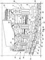
figure 1 is a raised schematic side view illustrating a machine for the automatic production of packages consisting of groups of beverage cans and the like; -
figure 2 is a plan view from above of the machine shown infigure 1 ; -
figure 3 is a perspective view of an inlet area to a device for forming the package used in the machine offigures 1 and2 ; -
figure 4 is a perspective view of the package-forming device already partly shown infigure 3 according to a different angle; -
figure 4b is an enlarged perspective view of a lower part of the package-forming device shown infigure 4 according to a different angle; -
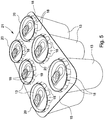
figure 5 shows, in a perspective view, a package once formed in the machine offigures 1 and2 with the device offigures 3 ,4 and4b ; -
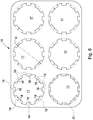
figure 6 is a plan view from above of a blank or packaging element before the intervention of the device of the previous figures; -
figure 7 is a raised side view of a plate from which overturned glass-shaped elements forming part of a pressing element extend downwards, which act on the blank to position it stably over the cans flanked in pairs, shown exploded from the same; -
figure 8 is a view from above of the plate offigure 7 with the cans indicated in dashes and dots; -
figure 9 is a plan view from above of a further embodiment of a machine according to the present invention. - With reference to the figures, by way of non-limiting example, an embodiment is shown of a device for the automatic insertion in an operating position of a cardboard blank or the like on groups of cans previously formed, positioning them in pairs adjacent to each other.
- This device is arranged inside a machine for the automatic production of packages consisting of groups of adjacent beverage cans and the like 11 wherein a
station 12 forfeeding cans 13 arranged adjacent to each other in pairs, astation 14 for feedingblanks 15 and a station for operationally positioning 16 saidblanks 15 on groups ofcans 13, are essentially provided. - The term "blanks" 15 refers to flat sheet elements generated from a single sheet, preferably but not limited to cardboard or the like and for example generated from recycled paper material or the like.
- These flat sheet elements are suitably shear-moulded or by means of suitable dies (not shown) to generate a pre-cut product to be applied to the upper part of the
cans 13 arranged in groups of two, four, six but always in pairs aligned and adjacent to each other. The blank 15 therefore provides at least a couple of paired openings for at least a pair of cans. In particular,figure 6 shows an example of this blank 15 wherein sixopenings 17 have been formed by punching or iron shearing, adjacent to each other in pairs to receive three pairs of adjacent cans. Eachopening 17 has a series ofteeth 18 protruding radially towards the inside of the maximum diameter of theopening 17, on one of its peripheral edges, arranged both individually and in close pairs according to an alternating arrangement. Saidteeth 18 are provided with bending invitation lines or yieldinglines 19 which favour the bending of the teeth and their positioning in correspondence with aperimetric edge 20 obtained at the top of acan 13. Theupper edge 20 is generated during the formation phase and closure of the same can 13 and protrudes towards the outside of the cylindrical side surface in correspondence with at least one of its ends. - Very briefly, the
feeding station 12 ofcans 13 allows and determines the reception of the cans on an underlying conveyor and arranges them one after another in two parallel, separate rows . - The two rows of
cans 13 are then juxtaposed side by side and divided intogroups 21 ofcans 13 of the established number of two, four six, etc., which in the example shown are six. - Once these groups have been formed, the
feeding station 14 ofblanks 15 is provided inside the machine for the automatic production of packages. - The
blanks 15 are positioned for example in aloader 22, stacked on top of each other, and from there are gripped by a manipulator orfeeder 23 of the rotating type which, for example through pairs ofsuckers 34, takes them from theloader 22 and moves them and places them one at a time on a respective group ofcans 21 which has been previously formed (figures 1 and3 ) and which is moving forwards. - At this point, the
operational positioning station 16 of saidblanks 15 is provided in the machine, where the device for the automatic insertion in an operating position of a cardboard blank 15 or similar on groups ofcans 21 according to the present invention is positioned. - The two rows of
cans 13 adjacent to each other are divided intogroups 21 and moved forward by anunderlying conveyor 35. Immediately afterwards, the pairs ofadjacent cans 13 of thegroups 21 are blocked and kept in relative position side by side ingroups 21 by a gripping group, which is also moving forward. This blocking position between thecans 13 is achieved by means of a series of pairs ofside gripping elements 24 which act on the two longitudinal sides of thegroup 21 ofcans 13 formed, to produce said gripping group. In the example illustrated, eachgripping element 24 of each pair of thesegripping elements 24 of the gripping group provides threeseats 25 which copy a half of thecan 13 of thegroup 21 of cans. Consequently, two opposinggripping elements 24, when paired with each other, embrace, on opposite sides, two adjacent cans of a group of cans formed 21 and carry it forwards constrained so that in the example the sixcans 13 are kept perfectly aligned and spaced apart in pairs of twos. As already indicated, the gripping group causes the advancement of a series of grippingelements 24 arranged one after another and on both sides of the cans: the cans are arranged in groups and this advance movement is effected for example by means of chain elements arranged in aloop 46 which rotate continuously. - It is above these
gripping elements 24, thus arranged to constrain pairs ofcans 13 of agroup 21, or above the group ofcans 21, that a blank 15 (figure 3 ) is placed by means of thefeeder 23, which uses pairs ofsuckers 34. This blank 15 is placed resting in a centered position with respect to thecans 13 of thegroup 21 so that each opening 17 of the six openings is arranged in correspondence with a respectiveperimetric edge 20 formed protruding and present on top of each can 13. - It should also be noted that the device for automatically inserting a cardboard blank 15 or similar on a group of
cans 21 according to the invention in an operating position, in addition to the gripping group of the group of cans, also provides a group for inserting the blank onto the group of cans formed (figure 4 ). - This group for inserting the blank onto the group of cans formed is positioned above the groups of
cans 21 thus formed (figure 4 ) which are brought forwards beneath said insertion group. Said insertion group of the blank comprisespressing elements 26 which are caused to press on the blank 15 maintained in the above arrangement. - The
pressing elements 26, in fact, move between a raised detached position above each upperperimetric edge 20 of each can 13 to a lowered position to push the blank 15, or itsopenings 17, to become firmly positioned on theedges 20 of thecans 13 which thus enter theopenings 17. - More specifically, the blank 15 is positioned resting against the
cans 13 of thegroup 21 so that each opening 17 of the six openings is arranged in correspondence with a respectiveperimetric edge 20 formed at the top of each can 13. Thepressing elements 26 are arranged one after another and are caused to move so as to follow the gripping groups in synchronism, each carrying agroup 21 ofcans 13 to be positioned in a blank 15 to form the single finished packaging. - In particular, each
pressing element 26 provides a vertical upright 27, bearing aplate 28 below, from which overturned glass-shaped elements 29 extend and act on the blank 15 (figures 3 and4 ). More specifically, each glass-shaped element 29 has a lower edge of its internal cavity which is provided with anannular countersink 48 facing outwardly for widening which facilitates the bending of theteeth 18.Figure 7 shows glass-shaped elements 29 positioned aboveperimetric edges 20, formed on top of eachcan 13. The overturned glass-shaped elements 29 when moved downwards push the blank 15, or itsopenings 17, onto the blank 15, to be firmly positioned on theedges 20 of thecans 13 that enter theopenings 17 of the same blank 15. - This essentially
circular countersink 48 has a size of the internal diameter equal to or rather slightly greater than the minimum internal diameter D of theopening 17 in correspondence with theteeth 18. At the same time, this lower edge must be smaller than the maximum diameter of theopening 17 in correspondence with the bending invitation lines or yieldinglines 19 which favour the bending of the teeth produced in the blank 15. - It should also be noted that the single vertical upright 27 can slide vertically upwards and downwards on
guides 30, for example with a column which are carried by achain carousel 31 arranged in a closed loop. Thesingle upright 27 also has apin 32 at the rear which controls its vertical movement (figure 3 ). Thepin 32 is in fact inserted in acam path 33 obtained by means of a recessed track fixed inside thechain carousel 31 which is arranged in a closed loop around the track. - The
cam path 33 is arranged so that the singlevertical upright 27 is caused to move downwards (according to the arrows F) when it is brought over agroup 21 ofcans 13 with the relative blank 15 resting in a centered position with respect to thecans 13 of thegroup 21, carried forwards by a pair ofgripping elements 24 of the gripping group. - Moving downwards, the vertical upright carries the
plate 28 and in this example, the six overturned glass-shapedelements 29, downwards so that they can act on the blank 15. - Consequently each glass-shaped
element 29 causes its lower edge to be positioned around therespective opening 17 of the blank 15 and the continuation of the pushing and pressing action causes the blank 15 to be inserted on theperimetric edges 20 of the sixcans 13. - More specifically, the pressing action causes the series of
teeth 18 protruding radially towards the inside of the maximum diameter of theopening 17 to be arranged beneath theperimetric edge 20 obtained on top of thesingle can 13. This occurs thanks to the presence of the bending invitation lines or yieldinglines 19 that favour the bending of the teeth and their positioning beneath theperimetric edge 20 of thecans 13. - The arrangement shown in
figure 5 is thus achieved, wherein thecans 13 are held firmly by theteeth 18 of the blank 15 to form a finished package defined with thegroup 21. - The gripping group and the group for inserting the blank onto the
group 21 ofcans 13 of the device for automatically inserting a cardboard blank or the like in an operating position are moved in synchronism with each other. - The finished packaging is then discharged downstream of the machine for the automatic production of packages consisting of groups of beverage cans and the like which has the device according to the present invention.
- It should be considered that the downwardly overturned glass-shaped
elements 29 arranged on the edge of theplate 28 integral with the respectivevertical upright 27 of thepressure element 26 can be adapted to the type ofcan 13 to be treated. These glasses can in fact be substituted according to the type of can to be positioned within the corresponding blank to produce thefinished packaging 11 containing the group ofcans 13. There are in fact cans with a diameter of 63 mm and cans with a diameter of 61 mm and according to these, overturned glass-shapedelements 29 must be provided, having a suitable diameter with an internal diameter of thecountersink 48 of 56 mm and 54 mm respectively. In particular it should be noted that these overturned glass-shapedelements 29 as shown infigure 7 can be made integral with theplate 28 by means ofbolts 47. Furthermore, in order to facilitate the positioning of the blank 15 on thecans 13 or rather theteeth 18 below and in correspondence with theperimetric edge 20 provided on top of each can 13, the lower mouth of the overturned glass-shapedelements 29 provides the above-mentionedannular countersink 48 facing outwardly for widening which facilitates the bending of theteeth 18 and which facilitates the action of the overturned glass-shapedelements 29 when they act on the blank 15. - Consequently each glass-shaped
element 29 causes its lower edge to be positioned around therespective opening 17 of the blank 15 and the continuation of the pushing and pressing action causes the blank 15 to be inserted on the edges of the sixcans 13. -
Figure 9 is a plan view from above of a further embodiment of a machine according to the present invention which uses the same reference numbers for the same elements. - In this representation, the feeding
station 12 ofcans 13 positioned in pairs adjacent to each other on the underlying conveyor forms the arrangement in two parallel rows of the cans one after another, simply already adjacent to each other in their packaging position, a position, moreover, which already infigure 2 , was obtained by guides or side deviators 36 schematically represented by continuous lines after they had been separated into groups in the feedingstation 12 for example by the twotoothed stars 37. - Also in this case, two series of
side gripping elements 24 are provided, which act on the two longitudinal sides of thegroup 21 ofcans 13 already flanked and adjacent to each other. The gripping elements act in pairs to form the stable blocking position of thecans 13 already flanked and adjacent to each other. As in the example shown infigure 2 , each grippingelement 24 of each pair of saidgripping elements 24 of the gripping unit provides threeseats 25 which copy a half of thecan 13 of thegroup 21 of cans. Consequently two opposinggripping elements 24, when brought together in pairs, embrace, on opposite sides, two cans already flanked and adjacent to each other of a group ofcans 21 and simply carry it forwards keeping the sixcans 13 perfectly aligned, in pairs of twos. - In this second example, the above-mentioned chain elements arranged in a
loop 46 which continuously rotate are positioned along linear paths with final connection curves and motion reversal. In the first example described, their path was more shaped with tilted and straight sections in addition to the final connecting curves, all clearly visible from the views offigures 2 and9 . - The objective mentioned in the preamble of the description has therefore been achieved.
- The protection scope of the present invention is defined by the attached claims.
Claims (12)
- A device for the automatic insertion in an operating position of a cardboard blank or the like on groups of cans to form a package suitable for being positioned in a machine for the automatic production of packagings essentially comprising a feeding station (12) of cans (13) adjacent to each other in two rows, a feeding station (14) of blanks (15) and an operationally positioning station (16) of said blanks (15) on groups (21) of cans (13), wherein said blank (15) provides at least a couple of paired openings (17), the device comprising a gripping group of the cans in two adjacent rows and a group for inserting the blank on the group of cans formed, wherein said insertion group provides a series of pressing elements (26) arranged one after another and caused to move in synchronism with said gripping group that carries said groups (21) of cans (13) forwards, characterized in that each opening (17) of said blank provides, on its perimetric edge, a series of teeth (18) protruding radially towards the inside of the maximum diameter of the opening (17) and said teeth (18) are provided with bending invitation lines or yielding lines (19) which favour the bending of the teeth and their positioning in correspondence with a perimetric edge (20) formed on top of each can (13), each of said pressing elements (26) providing hollow overturned glass-shaped elements (29) provided with an essentially circular lower edge (48) that move between a raised detached position above each upper perimetric edge (20) of each can (13) to a lowered position to push the blank (15), or its openings (17) to become firmly positioned on said edges (20) of the cans (13) that enter the openings (17), wherein said lower edge (48) has a dimension of the internal diameter equal to or rather slightly greater than the minimum internal diameter D of the opening (17) in correspondence with the teeth (18) and at the same time it must be less than the maximum diameter of the opening (17) in correspondence with said bending invitation lines or yielding lines (19).
- The device according to claim 1, characterized in that said pressing elements (26) each comprise a respective vertical upright (27), carrying a plate (28) in its lower part, from which the overturned glass-shaped elements (29) extend downwards and act on the blank (15).
- The device according to claim 2, characterized in that each vertical upright (27) can slide vertically upwards and downwards on guides (30), for example in a column, which are carried by a chain carousel (31) arranged in a closed loop.
- The device according to claim 3, characterized in that each vertical upright (27) has a pin (32) at its rear which controls its vertical movement, wherein said single pin (32) is inserted in a cam path (33) obtained through a recessed track fixed inside the chain carousel (31).
- The device according to claim 4, characterized in that said cam path (33) is arranged so that the single vertical upright (27) is caused to move downwards when it is brought above a group (21) of cans (13) with its relative blank (15) positioned with its openings (17) resting centered with respect to the cans (13) of the group (21), wherein each group of cans is carried forward by a pair of gripping elements (24) forming part of the gripping group.
- The device according to one or more of the previous claims, characterized in that said gripping group of the adjacent cans comprises a series of pairs of side pincer gripping elements (24) which act on the two longitudinal sides of each group (21) of cans (13) formed.
- The device according to claim 6, characterized in that each gripping element (24) of each pair of said gripping elements (24) of the gripping group provides seats (25) which copy a half of each can (13) of the group (21) of cans.
- The device according to claim 7, characterized in that two opposite gripping elements (24), when paired together, embrace, on opposite side, two adjacent cans (13) of a group of cans formed (21) and carry it forward thus constrained.
- The device according to one or more of the previous claims from 5 to 8, characterized in that pairs of cans are kept perfectly aligned and spaced apart in pairs of twos.
- The device according to claim 6, characterized in that said gripping group causes the advancement of a series of gripping elements (24) positioned one after another and on both sides of the cans (13) wherein said cans (13) are arranged in groups (21) and said advance movement is effected by means of chain elements arranged in a loop (46) which rotate continuously.
- The device according to one or more of the previous claims, characterized in that said blank (15) is arranged above said groups of cans advancing through a feeder (23), which uses pairs of suckers (34) and takes one blank (15) at a time from a loader (22).
- The device according to one or more of the previous claims, characterized in that said blank (15) is arranged above said advancing groups of cans resting centered with respect to said pairs of cans (13) of the group (21) so that each opening (17) provided in said blank (15) is positioned in correspondence with a respective perimetric edge (20) formed protruding and present on top of each can (13).
Applications Claiming Priority (2)
| Application Number | Priority Date | Filing Date | Title |
|---|---|---|---|
| IT102019000000226A IT201900000226A1 (en) | 2019-01-09 | 2019-01-09 | DEVICE FOR THE AUTOMATIC PLACEMENT IN THE OPERATING POSITION OF A CARDBOARD OR SIMILAR BLANK ON GROUPS OF CANS TO CREATE A PACKAGE |
| IT201900019631 | 2019-10-23 |
Publications (1)
| Publication Number | Publication Date |
|---|---|
| EP3680183A1 true EP3680183A1 (en) | 2020-07-15 |
Family
ID=68848208
Family Applications (1)
| Application Number | Title | Priority Date | Filing Date |
|---|---|---|---|
| EP19216857.3A Pending EP3680183A1 (en) | 2019-01-09 | 2019-12-17 | Device for the automatic insertion in an operating position of a cardboard blank or the like on groups of cans to form a packaging |
Country Status (1)
| Country | Link |
|---|---|
| EP (1) | EP3680183A1 (en) |
Cited By (5)
| Publication number | Priority date | Publication date | Assignee | Title |
|---|---|---|---|---|
| EP3943426A1 (en) * | 2020-07-24 | 2022-01-26 | WestRock Packaging Systems, LLC | Container gripper |
| US11878875B2 (en) | 2021-05-17 | 2024-01-23 | Tawhid Farag | Comb for spacing apart a series of articles |
| WO2024097174A1 (en) * | 2022-10-31 | 2024-05-10 | Westrock Packaging Systems, Llc | Packaging system, apparatus and method of constructing an article carrier |
| DE102024131763A1 (en) * | 2024-10-30 | 2026-04-30 | Krones Aktiengesellschaft | Packaging machine and method for producing containers |
| CN122324344A (en) * | 2026-06-02 | 2026-07-03 | 杭州新希望双峰乳业有限公司 | An automatic bottle-closing machine |
Citations (4)
| Publication number | Priority date | Publication date | Assignee | Title |
|---|---|---|---|---|
| DE1186393B (en) * | 1959-05-02 | 1965-01-28 | Illinois Tool Works | Device for assembling several containers with a carrier made of elastic material |
| US5125506A (en) * | 1991-04-18 | 1992-06-30 | Imperial Packaging Inc. | Carriers of multiples of flanged containers |
| WO2009097546A1 (en) | 2008-02-01 | 2009-08-06 | Meadwestvaco Packaging Systems, Llc | Twin packaging line and metering system |
| WO2018049429A1 (en) * | 2016-09-12 | 2018-03-15 | Westrock Packaging Systems, Llc | Applicator plate, apparatus and method |
-
2019
- 2019-12-17 EP EP19216857.3A patent/EP3680183A1/en active Pending
Patent Citations (4)
| Publication number | Priority date | Publication date | Assignee | Title |
|---|---|---|---|---|
| DE1186393B (en) * | 1959-05-02 | 1965-01-28 | Illinois Tool Works | Device for assembling several containers with a carrier made of elastic material |
| US5125506A (en) * | 1991-04-18 | 1992-06-30 | Imperial Packaging Inc. | Carriers of multiples of flanged containers |
| WO2009097546A1 (en) | 2008-02-01 | 2009-08-06 | Meadwestvaco Packaging Systems, Llc | Twin packaging line and metering system |
| WO2018049429A1 (en) * | 2016-09-12 | 2018-03-15 | Westrock Packaging Systems, Llc | Applicator plate, apparatus and method |
Cited By (8)
| Publication number | Priority date | Publication date | Assignee | Title |
|---|---|---|---|---|
| EP3943426A1 (en) * | 2020-07-24 | 2022-01-26 | WestRock Packaging Systems, LLC | Container gripper |
| WO2022020820A1 (en) * | 2020-07-24 | 2022-01-27 | Westrock Packaging Systems, Llc | Container gripper |
| CN116194371A (en) * | 2020-07-24 | 2023-05-30 | 维实洛克包装系统有限公司 | container gripper |
| US11866270B2 (en) | 2020-07-24 | 2024-01-09 | Westrock Packaging Systems, Llc | Container gripper |
| US11878875B2 (en) | 2021-05-17 | 2024-01-23 | Tawhid Farag | Comb for spacing apart a series of articles |
| WO2024097174A1 (en) * | 2022-10-31 | 2024-05-10 | Westrock Packaging Systems, Llc | Packaging system, apparatus and method of constructing an article carrier |
| DE102024131763A1 (en) * | 2024-10-30 | 2026-04-30 | Krones Aktiengesellschaft | Packaging machine and method for producing containers |
| CN122324344A (en) * | 2026-06-02 | 2026-07-03 | 杭州新希望双峰乳业有限公司 | An automatic bottle-closing machine |
Similar Documents
| Publication | Publication Date | Title |
|---|---|---|
| US4002005A (en) | Package of nested containers and method and apparatus for producing same | |
| US3851441A (en) | Machine for producing filled two-lidded plastic containers with a drinking straw and a puncturable depression in each lower lid | |
| AU665549B2 (en) | Packaging | |
| US6094890A (en) | Thermoforming, filling, and capping receptacles | |
| JP3868490B2 (en) | Multi-pack packaging equipment | |
| JP6067017B2 (en) | Carton forming apparatus and method | |
| CN102648135B (en) | A container carrier | |
| EP0707550B1 (en) | Methods for conveying objects through apparatus, packing apparatus and methods for packing materials in cartons | |
| EP2643221B1 (en) | A machine and system for applying container carriers to containers | |
| AU4044993A (en) | Multiple container carriers and machine for installing carriers on containers | |
| NZ319886A (en) | Overhead assembly for use in a packaging machine which opens and lowers cartons onto groups of articles | |
| CN104540687A (en) | Embossing a flat metal blank (method, tool and object) | |
| US4194440A (en) | Method and apparatus for making drum-shaped cardboard containers | |
| CN108472910B (en) | Operation assembly of cartoning machine, cartoning machine and method for forming cartons | |
| US3923200A (en) | Feeder for sleeve-enclosed edible cones | |
| US3303631A (en) | Machine for and method of applying carriers to containers | |
| US20160288936A1 (en) | Apparatus and method for packing a product in a container comprising an external body and an internal bag | |
| EP3889054B1 (en) | Packaging process in a packaging machine of groups of cans | |
| JPS6127261B2 (en) | ||
| JP3905598B2 (en) | Article sorting device | |
| US12344416B2 (en) | Device and method for setting up containers having a functional edge from flat blanks | |
| RU2321495C2 (en) | Container forming system, especially, containers for food products | |
| CA2485075A1 (en) | Method and packaging machine for producing sealed packages of pourable food products from precut blanks of sheet packaging material | |
| CN117545697A (en) | System and method for packaging articles within a carton | |
| CN116648337A (en) | Tool Holder Assemblies and Assemblies |
Legal Events
| Date | Code | Title | Description |
|---|---|---|---|
| PUAI | Public reference made under article 153(3) epc to a published international application that has entered the european phase |
Free format text: ORIGINAL CODE: 0009012 |
|
| STAA | Information on the status of an ep patent application or granted ep patent |
Free format text: STATUS: THE APPLICATION HAS BEEN PUBLISHED |
|
| AK | Designated contracting states |
Kind code of ref document: A1 Designated state(s): AL AT BE BG CH CY CZ DE DK EE ES FI FR GB GR HR HU IE IS IT LI LT LU LV MC MK MT NL NO PL PT RO RS SE SI SK SM TR |
|
| AX | Request for extension of the european patent |
Extension state: BA ME |
|
| STAA | Information on the status of an ep patent application or granted ep patent |
Free format text: STATUS: REQUEST FOR EXAMINATION WAS MADE |
|
| 17P | Request for examination filed |
Effective date: 20201222 |
|
| RBV | Designated contracting states (corrected) |
Designated state(s): AL AT BE BG CH CY CZ DE DK EE ES FI FR GB GR HR HU IE IS IT LI LT LU LV MC MK MT NL NO PL PT RO RS SE SI SK SM TR |
|
| STAA | Information on the status of an ep patent application or granted ep patent |
Free format text: STATUS: EXAMINATION IS IN PROGRESS |
|
| 17Q | First examination report despatched |
Effective date: 20221220 |