EP3680174B1 - Drehantriebssysteme und verfahren zum antrieb von fahrzeugen unter verwendung von drehantriebssystemen - Google Patents
Drehantriebssysteme und verfahren zum antrieb von fahrzeugen unter verwendung von drehantriebssystemen Download PDFInfo
- Publication number
- EP3680174B1 EP3680174B1 EP19208975.3A EP19208975A EP3680174B1 EP 3680174 B1 EP3680174 B1 EP 3680174B1 EP 19208975 A EP19208975 A EP 19208975A EP 3680174 B1 EP3680174 B1 EP 3680174B1
- Authority
- EP
- European Patent Office
- Prior art keywords
- fan
- permanent magnet
- electric motor
- rotation axis
- rotational speed
- Prior art date
- Legal status (The legal status is an assumption and is not a legal conclusion. Google has not performed a legal analysis and makes no representation as to the accuracy of the status listed.)
- Active
Links
Images
Classifications
-
- B—PERFORMING OPERATIONS; TRANSPORTING
- B64—AIRCRAFT; AVIATION; COSMONAUTICS
- B64C—AEROPLANES; HELICOPTERS
- B64C11/00—Propellers, e.g. of ducted type; Features common to propellers and rotors for rotorcraft
- B64C11/46—Arrangements of, or constructional features peculiar to, multiple propellers
- B64C11/48—Units of two or more coaxial propellers
-
- B—PERFORMING OPERATIONS; TRANSPORTING
- B60—VEHICLES IN GENERAL
- B60K—ARRANGEMENT OR MOUNTING OF PROPULSION UNITS OR OF TRANSMISSIONS IN VEHICLES; ARRANGEMENT OR MOUNTING OF PLURAL DIVERSE PRIME-MOVERS IN VEHICLES; AUXILIARY DRIVES FOR VEHICLES; INSTRUMENTATION OR DASHBOARDS FOR VEHICLES; ARRANGEMENTS IN CONNECTION WITH COOLING, AIR INTAKE, GAS EXHAUST OR FUEL SUPPLY OF PROPULSION UNITS IN VEHICLES
- B60K1/00—Arrangement or mounting of electrical propulsion units
- B60K1/02—Arrangement or mounting of electrical propulsion units comprising more than one electric motor
-
- B—PERFORMING OPERATIONS; TRANSPORTING
- B60—VEHICLES IN GENERAL
- B60L—PROPULSION OF ELECTRICALLY-PROPELLED VEHICLES; SUPPLYING ELECTRIC POWER FOR AUXILIARY EQUIPMENT OF ELECTRICALLY-PROPELLED VEHICLES; ELECTRODYNAMIC BRAKE SYSTEMS FOR VEHICLES IN GENERAL; MAGNETIC SUSPENSION OR LEVITATION FOR VEHICLES; MONITORING OPERATING VARIABLES OF ELECTRICALLY-PROPELLED VEHICLES; ELECTRIC SAFETY DEVICES FOR ELECTRICALLY-PROPELLED VEHICLES
- B60L50/00—Electric propulsion with power supplied within the vehicle
- B60L50/10—Electric propulsion with power supplied within the vehicle using propulsion power supplied by engine-driven generators, e.g. generators driven by combustion engines
-
- B—PERFORMING OPERATIONS; TRANSPORTING
- B64—AIRCRAFT; AVIATION; COSMONAUTICS
- B64D—EQUIPMENT FOR FITTING IN OR TO AIRCRAFT; FLIGHT SUITS; PARACHUTES; ARRANGEMENT OR MOUNTING OF POWER PLANTS OR PROPULSION TRANSMISSIONS IN AIRCRAFT
- B64D27/00—Arrangement or mounting of power plants in aircraft; Aircraft characterised by the type or position of power plants
- B64D27/02—Aircraft characterised by the type or position of power plants
- B64D27/30—Aircraft characterised by electric power plants
- B64D27/33—Hybrid electric aircraft
-
- B—PERFORMING OPERATIONS; TRANSPORTING
- B64—AIRCRAFT; AVIATION; COSMONAUTICS
- B64D—EQUIPMENT FOR FITTING IN OR TO AIRCRAFT; FLIGHT SUITS; PARACHUTES; ARRANGEMENT OR MOUNTING OF POWER PLANTS OR PROPULSION TRANSMISSIONS IN AIRCRAFT
- B64D35/00—Transmitting power from power plants to propellers or rotors; Arrangements of transmissions
- B64D35/02—Transmitting power from power plants to propellers or rotors; Arrangements of transmissions specially adapted for specific power plants
- B64D35/021—Transmitting power from power plants to propellers or rotors; Arrangements of transmissions specially adapted for specific power plants for electric power plants
- B64D35/022—Transmitting power from power plants to propellers or rotors; Arrangements of transmissions specially adapted for specific power plants for electric power plants of hybrid-electric type
- B64D35/024—Transmitting power from power plants to propellers or rotors; Arrangements of transmissions specially adapted for specific power plants for electric power plants of hybrid-electric type of series type
-
- B—PERFORMING OPERATIONS; TRANSPORTING
- B64—AIRCRAFT; AVIATION; COSMONAUTICS
- B64D—EQUIPMENT FOR FITTING IN OR TO AIRCRAFT; FLIGHT SUITS; PARACHUTES; ARRANGEMENT OR MOUNTING OF POWER PLANTS OR PROPULSION TRANSMISSIONS IN AIRCRAFT
- B64D35/00—Transmitting power from power plants to propellers or rotors; Arrangements of transmissions
- B64D35/02—Transmitting power from power plants to propellers or rotors; Arrangements of transmissions specially adapted for specific power plants
- B64D35/021—Transmitting power from power plants to propellers or rotors; Arrangements of transmissions specially adapted for specific power plants for electric power plants
- B64D35/026—Transmitting power from power plants to propellers or rotors; Arrangements of transmissions specially adapted for specific power plants for electric power plants the electric power plant being integral with the propeller or rotor
-
- H—ELECTRICITY
- H02—GENERATION; CONVERSION OR DISTRIBUTION OF ELECTRIC POWER
- H02K—DYNAMO-ELECTRIC MACHINES
- H02K16/00—Machines with more than one rotor or stator
- H02K16/02—Machines with one stator and two or more rotors
-
- H—ELECTRICITY
- H02—GENERATION; CONVERSION OR DISTRIBUTION OF ELECTRIC POWER
- H02K—DYNAMO-ELECTRIC MACHINES
- H02K7/00—Arrangements for handling mechanical energy structurally associated with dynamo-electric machines, e.g. structural association with mechanical driving motors or auxiliary dynamo-electric machines
- H02K7/10—Structural association with clutches, brakes, gears, pulleys or mechanical starters
- H02K7/116—Structural association with clutches, brakes, gears, pulleys or mechanical starters with gears
-
- H—ELECTRICITY
- H02—GENERATION; CONVERSION OR DISTRIBUTION OF ELECTRIC POWER
- H02K—DYNAMO-ELECTRIC MACHINES
- H02K7/00—Arrangements for handling mechanical energy structurally associated with dynamo-electric machines, e.g. structural association with mechanical driving motors or auxiliary dynamo-electric machines
- H02K7/14—Structural association with mechanical loads, e.g. with hand-held machine tools or fans
-
- H—ELECTRICITY
- H02—GENERATION; CONVERSION OR DISTRIBUTION OF ELECTRIC POWER
- H02K—DYNAMO-ELECTRIC MACHINES
- H02K7/00—Arrangements for handling mechanical energy structurally associated with dynamo-electric machines, e.g. structural association with mechanical driving motors or auxiliary dynamo-electric machines
- H02K7/18—Structural association of electric generators with mechanical driving motors, e.g. with turbines
- H02K7/1807—Rotary generators
- H02K7/1823—Rotary generators structurally associated with turbines or similar engines
-
- H—ELECTRICITY
- H02—GENERATION; CONVERSION OR DISTRIBUTION OF ELECTRIC POWER
- H02K—DYNAMO-ELECTRIC MACHINES
- H02K7/00—Arrangements for handling mechanical energy structurally associated with dynamo-electric machines, e.g. structural association with mechanical driving motors or auxiliary dynamo-electric machines
- H02K7/20—Structural association with auxiliary dynamo-electric machines, e.g. with electric starter motors or exciters
-
- B—PERFORMING OPERATIONS; TRANSPORTING
- B60—VEHICLES IN GENERAL
- B60L—PROPULSION OF ELECTRICALLY-PROPELLED VEHICLES; SUPPLYING ELECTRIC POWER FOR AUXILIARY EQUIPMENT OF ELECTRICALLY-PROPELLED VEHICLES; ELECTRODYNAMIC BRAKE SYSTEMS FOR VEHICLES IN GENERAL; MAGNETIC SUSPENSION OR LEVITATION FOR VEHICLES; MONITORING OPERATING VARIABLES OF ELECTRICALLY-PROPELLED VEHICLES; ELECTRIC SAFETY DEVICES FOR ELECTRICALLY-PROPELLED VEHICLES
- B60L2200/00—Type of vehicles
- B60L2200/10—Air crafts
-
- B—PERFORMING OPERATIONS; TRANSPORTING
- B60—VEHICLES IN GENERAL
- B60L—PROPULSION OF ELECTRICALLY-PROPELLED VEHICLES; SUPPLYING ELECTRIC POWER FOR AUXILIARY EQUIPMENT OF ELECTRICALLY-PROPELLED VEHICLES; ELECTRODYNAMIC BRAKE SYSTEMS FOR VEHICLES IN GENERAL; MAGNETIC SUSPENSION OR LEVITATION FOR VEHICLES; MONITORING OPERATING VARIABLES OF ELECTRICALLY-PROPELLED VEHICLES; ELECTRIC SAFETY DEVICES FOR ELECTRICALLY-PROPELLED VEHICLES
- B60L2220/00—Electrical machine types; Structures or applications thereof
- B60L2220/50—Structural details of electrical machines
-
- B—PERFORMING OPERATIONS; TRANSPORTING
- B64—AIRCRAFT; AVIATION; COSMONAUTICS
- B64D—EQUIPMENT FOR FITTING IN OR TO AIRCRAFT; FLIGHT SUITS; PARACHUTES; ARRANGEMENT OR MOUNTING OF POWER PLANTS OR PROPULSION TRANSMISSIONS IN AIRCRAFT
- B64D27/00—Arrangement or mounting of power plants in aircraft; Aircraft characterised by the type or position of power plants
- B64D2027/005—Aircraft with an unducted turbofan comprising contra-rotating rotors, e.g. contra-rotating open rotors [CROR]
-
- B—PERFORMING OPERATIONS; TRANSPORTING
- B64—AIRCRAFT; AVIATION; COSMONAUTICS
- B64D—EQUIPMENT FOR FITTING IN OR TO AIRCRAFT; FLIGHT SUITS; PARACHUTES; ARRANGEMENT OR MOUNTING OF POWER PLANTS OR PROPULSION TRANSMISSIONS IN AIRCRAFT
- B64D35/00—Transmitting power from power plants to propellers or rotors; Arrangements of transmissions
- B64D35/04—Transmitting power from power plants to propellers or rotors; Arrangements of transmissions characterised by the transmission driving a plurality of propellers or rotors
- B64D35/06—Transmitting power from power plants to propellers or rotors; Arrangements of transmissions characterised by the transmission driving a plurality of propellers or rotors the propellers or rotors being counter-rotating
-
- Y—GENERAL TAGGING OF NEW TECHNOLOGICAL DEVELOPMENTS; GENERAL TAGGING OF CROSS-SECTIONAL TECHNOLOGIES SPANNING OVER SEVERAL SECTIONS OF THE IPC; TECHNICAL SUBJECTS COVERED BY FORMER USPC CROSS-REFERENCE ART COLLECTIONS [XRACs] AND DIGESTS
- Y02—TECHNOLOGIES OR APPLICATIONS FOR MITIGATION OR ADAPTATION AGAINST CLIMATE CHANGE
- Y02T—CLIMATE CHANGE MITIGATION TECHNOLOGIES RELATED TO TRANSPORTATION
- Y02T50/00—Aeronautics or air transport
- Y02T50/60—Efficient propulsion technologies, e.g. for aircraft
Definitions
- the subject matter disclosed herein generally relates to the propulsion systems, and more particularly to electric propulsion systems for vehicles like aircraft.
- Vehicles such as ships and aircrafts, commonly include propellers to provide motive force to the vehicles.
- the propellers are supported for rotation relative to the vehicle and are typically driven by an engine.
- the engine is generally connected mechanically to the propeller through a direct mechanical connection, such as through a coupling, to provide mechanical rotation to the propeller.
- the engine drive arrangement can be relatively noisy in comparison to closed rotor engines.
- a rotary propulsion system is provided as defined by claim 1.
- the fan includes a plurality of open-rotor fan blades having a scimitar shape.
- Embodiments may include a generator connected to the electric motor and a gas turbine engine operably connected to the generator wherein rotational speed of the gas turbine engine is independent of rotational speed of the fan.
- the reduction gear set includes a planetary gear arrangement.
- the planetary gear arrangement axially overlaps the electric motor.
- the planetary gear arrangement is axially offset from the electric motor.
- the planetary gear arrangement comprises a sun gear fixed in rotation relative to the permanent magnet, a ring gear fixed in rotation relative to the fan, and two or more planetary gears distributed circumferentially about the rotation axis and intermeshed with the sun gear and the ring gear.
- the second reduction gear set arranged axially on a side of the first reduction gear set opposite the electric motor.
- an aircraft is provided as defined by claim 8.
- the rotation axis is substantially horizontal relative to the direction of gravity when the aircraft is normal, level flight.
- the rotation axis is substantially vertical relative to the direction of gravity when the aircraft is normal, level flight.
- rotary propulsion systems are provided that allow for fans to operate at difference speeds, limiting noise.
- rotary propulsion systems are provided with reduction gear sets, allowing the employment of electric motors with relatively high power-density and high propulsive force and torque to the system fan.
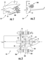
- FIG. 1 a partial view of an exemplary embodiment of a rotary propulsion system in accordance with the disclosure is shown in FIG. 1 and is designated generally by reference character 100.
- FIG. 2-13 Other embodiments of rotary propulsion systems, aircraft having rotary propulsion systems, and methods of propelling aircraft using rotary propulsion systems in accordance with the present disclosure, or aspects thereof, are provided in Figs. 2-13 , as will be described.
- the systems and methods described herein can be used for rotary propulsion systems for aircraft, such as in rotary propulsion systems employing contra-rotating fans, though the present disclosure is not limited to rotary propulsion systems employing control rotating fans or to aircraft in general.
- an aircraft 10 including the rotary propulsion system 100 e.g., a fixed-wing aircraft or a rotorcraft.
- the aircraft 10 includes an airframe 12 with one or more pylon 14.
- the pylon 14 supports the rotary propulsion system 100, which in the embodiment shown in FIGS. 1-3 includes a first fan 102 and a second fan 104 supported for rotation about a rotation axis 106.
- FIGS. 1-3 Although a specific architecture is shown in FIGS. 1-3 it is to be understood and appreciated that other aircraft architectures can also benefit from the present disclosure, such as aircraft architectures having a singular rotary propulsion system 100 or aircraft architectures having more than two rotary propulsion systems 100.
- the rotation axis 106 about which the rotary propulsion system 100 is arranged can be substantially horizontal relative to gravity during normal, level flight. It is also contemplated that, in accordance with certain embodiments, the rotation axis 106 about which the rotary propulsion system 100 is arranged can be substantially vertical relative to gravity during normal, level flight.
- the aircraft 10 includes a gas turbine engine 16 with a compressor section 18 and a turbine section 20, a generator 22 and a power bus 24.
- the gas turbine engine 16 is carried within the airframe 12 and is operatively connected to the generator 22.
- the generator 22 is configured to generate electrical power P for the rotary propulsion system 100 and is connected to the rotary propulsion system 100 by the power bus 24.
- the generator 22 is an alternating current (AC) generator configured and adapted to provide variable frequency AC power to the rotary propulsion system 100 to the control rotational speed and direction of the first fan 102 and the second fan 104.
- AC alternating current
- connection of the gas turbine engine 16 be indirect, gas turbine engine 16 providing rotation R to the generator 22, which the generator 22 converts to electrical power P for provision the rotary propulsion system 100 via the power bus 24.
- Rotational speed of the gas turbine engine 16 is therefore independent of rotational speed of the first fan 102 and the second fan 104.
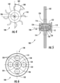
- the rotary propulsion system 100 includes a singular fan 102 arranged as an open-rotor.
- the fan 102 includes a plurality of fan blades 108 distributed circumferentially about the rotation axis 106 for rotary movement 109 about the rotation axis 106.
- the fan 102 includes eight (8) fan blades 108. This is for illustration purposes only and is non-limiting. As will be appreciated by those of skill in the art in view of the present disclosure the fan 102 can have fewer than eight (8) fan blades 108 or more than eight (8) fan blades 108, as suitable for an intended application.
- the fan blades 108 each have a scimitar shape 110, i.e., with increasing sweep along the leading edge of the blade, between radial inner and radially outer ends of the blade.
- the scimitar shape 110 of the fan blades 108 improving efficiency of the fan 102 during operation.
- the rotary propulsion system 100 includes a singular fan 102, a shaft 112, and electric motor 114 with windings 116 and one or more permanent magnet 118, and a reduction gear set 120.
- the fan 102 is arranged along the rotation axis 106.
- the electric motor 114 with the windings 116 and the one or more permanent magnet 118 is arranged along the rotation axis 106 is and is operatively connected to the fan 102.
- the reduction gear set 120 is arranged along the rotation axis 106 and couples the electric motor 114, the one or more permanent magnet 118 being rotatable relative the windings 116 and the fan 102 to rotate the fan 102 using the electric motor 114 at a rotational speed RF that is lower than a rotational speed RM of the one or more permanent magnet 118.
- the shaft 112 is fixed relative to the airframe 12.
- the windings 116 are fixed relative to the shaft 112 and are polyphase windings. In this respect the windings 116 receive AC power P from the generator 22 (shown in FIG. 3 ) and generate therewith a rotating magnetic field that rotates according to the frequency of AC power P.
- the one or more permanent magnet 118 is carried by a rotor 122 of the electric motor 114, is supported for rotation relative to the windings 116 by bearings 124, and is magnetically coupled to the one or more windings 116 across a gap 126 to rotate at a speed correlated to the frequency of the AC power applied to the windings 116.
- the reduction gear set 120 couples the rotor 122 of the electric motor 114 to the fan 102, which reduces rotational speed of the fan 102 relative to the rotor 122 according the gear ratio of the reduction gear set 120.
- the reduction gear set 120 includes a planetary gear arrangement 128.
- the planetary gear arrangement 128 axially overlaps the electric motor 114 (shown in FIG. 5 ) to provide an axially compact arrangement and includes a sun gear 130, a plurality of planetary gears 132 and a ring gear 134.
- the sun gear 130 is fixed in rotation relative to the permanent magnet 118 of the electric motor 114.
- the ring gear 134 is fixed in rotation relative to the singular fan 102 and extends circumferentially about the rotation axis 106.
- the plurality of planetary gears 132 are distributed circumferentially about the rotation axis 106 and are intermeshed with the sun gear 130 and the ring gear 134.
- the bearings 124 are arranged between the sun gear 130 and the shaft 112, the sun gear 130 thereby being rotatable relative to the shaft 112.
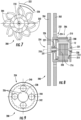
- the rotary propulsion system 200 is similar to the rotary propulsion system 100 (shown in FIG. 5 ) and additionally includes two fans.
- the rotary propulsion system 200 includes a first fan 202, a second fan 204, a first electric motor 206 with windings 208 and one or more permanent magnets 210, and a second electric motor 212 with windings 214 and one or more permanent magnets 216.
- the first fan 202 and the second fan 204 are each arranged along a rotation axis 218, the second fan 204 being arranged along the rotation axis 218 on a side of the first fan 202 opposite the first electric motor 206 and the second electric motor 212.
- the first fan 202 and the second fan 204 are contra-rotating, the first fan 202 arranged for rotation in a direction 220 opposite a rotation direction 222 of the second fan 204.
- the rotational speed of the second fan 204 may be different than that of the first fan 202, e.g., faster or slower.
- varying the rotational speed of one of the first fan 202 and the second fan 204 relative to the other of the first fan 202 and the second fan 204 can limit the noise of the rotary propulsion system 200 during operation.
- the windings 208 of the first electric motor 206 and the windings 214 of the second electric motor 212 are both fixed relative to the airframe 12.
- the permanent magnets 210 of the first electric motor 206 and the permanent magnets 216 of the second electric motor 212 are each supported for rotation relative to airframe 12 in a radial flux-type arrangement.
- the one or more permanent magnet 210 of the first electric motor 206 is arranged on a first rotor 224, is arranged for rotation about the rotation axis 218, is supported by first bearings 226 for rotation relative to the airframe 12, and is supported by second bearings 227 for rotation relative to the second electric motor 212.
- the one or more permanent magnet 216 of the second electric motor 212 is arranged on a second rotor 228 and is arranged for rotation about the rotation axis 218, the windings 208 and the one or more permanent magnet 210 of the first electric motor 206 extending circumferentially about the windings 214 and the one or more permanent magnet 216 of the second electric motor 212.
- the one or more permanent magnet 216 of the second electric motor 212 is in turn fixed relative to a shaft 230, the shaft 230 in turn being supported for rotation relative to the airframe 12 by third bearings 231.
- a first reduction gear set 232 couples the first fan 202 to the first electric motor 206 and a second reduction gear set 234 couples the second fan 204 to the second electric motor 212.
- the first reduction gear set 232 is similar to the reduction gear set 120 (shown in FIG. 5 ) and supports the first fan 202 for rotation at a rotational speed that is lower than a rotational speed of the first electric motor 206 according to the gear ratio of the first reduction gear set 232.
- the second reduction gear set 234 supports the second fan 204 for rotation relative to the second electric motor 212 according to the gear ratio of the second reduction gear set 234.
- the second reduction gear set 234 includes a planetary gear arrangement 236.
- the planetary gear arrangement 236 is axially offset from the first electric motor 206 (shown in FIG. 8 ) and the second electric motor 212 (shown in FIG. 8 ) and includes sun gear 238, a plurality of planetary gears 240, and a ring gear 242.
- the sun gear 238 is arranged along the rotation axis 218 and is fixed relative to the shaft 230.
- the ring gear 242 extends about the sun gear 238 (shown in FIG. 7 ) and is fixed relative to the second fan 204 (shown in FIG. 8 ).
- the plurality of planetary gears 240 are distributed circumferentially about the sun gear 238 and are intermeshed with the sun gear 238 and the ring gear 242.
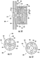
- the rotary propulsion system 300 is similar to the rotary propulsion system 200 (shown in FIG. 7 ) and additionally includes a first electric motor 302 and a second electric motor 304 having axial flux-type arrangements.
- the first electric motor 302 is operatively associated with a first fan 306 and includes a winding 308 and one or more permanent magnet 310.
- the winding 308 of the first electric motor 302 is fixed relative to the airframe 12 and extends radially from a rotation axis 312.
- the one or more permanent magnet 310 of the first electric motor 302 is supported by a rotor 314, extends radially from the rotation axis 312, and is axially spaced from the winding 308 by an axial gap 316.
- the rotor 314 includes a shaft portion 318 that extends along the rotation axis 312, is supported for rotation about the rotation axis 312 relative to the winding 308 by a bearings 320, and is coupled to the first fan 306 by a first reduction gear set 322.
- the first reduction gear set 322 includes a planetary gear arrangement 324.
- the planetary gear arrangement 324 includes a ring gear 326, a plurality of planetary gears 328 and a sun gear 330.
- the ring gear 326 extends circumferentially about the rotation axis 312 and is fixed to relative to the first fan 306.
- the plurality of planetary gears 328 are distributed about the rotation axis 312 and are intermeshed with the ring gear 326 and the sun gear 330.
- the sun gear 330 is arranged along the rotation axis 312, is fixed in rotation relative to the shaft portion 318 (shown in FIG.
- the first reduction gear set 322 allows the first fan 306 to rotate at a rotational speed that is lower than a rotational speed of the first electric motor 302 according to the gear ratio of the first reduction gear set 322, enabling the use of a relatively high-speed motor run at high speed to provide high torque to the first fan 306.
- the second electric motor 304 is arranged on a side of the first electric motor 302 axially opposite the first fan 306, includes a winding 336 and one or more permanent magnet 338, and is operatively connected to a second fan 340 through a second reduction gear set 342.
- the winding 336 is fixed to the airframe 12, extends radially from the rotation axis 312, and opposes the one or more permanent magnet 338 across an axial gap 343.
- the one or more permanent magnet 338 extends radially from the rotation axis 312 and is fixed relative to the shaft 332.
- the shaft 332 is arranged along the rotation axis 312 and is supported for rotation relative to the airframe 12 relative by bearings 346.
- the shaft 332 is also supported for rotation relative to the shaft portion 318 by bearings 350 and is further supported for rotation relative to the sun gear 330 (shown in FIG. 11 ) of the first reduction gear set 322 by the bearings 334. This allows the shaft 332 to rotate about the rotation axis 312 independent of both the first electric motor 302 and the first fan 306, thereby operably connecting the second electric motor 304 to the second fan 340.
- the second reduction gear set 342 includes a planetary gear arrangement 344 including a ring gear 346, a plurality of planetary gears 348 and a sun gear 350.
- the ring gear 346 extends about the rotation axis 312 and is fixed relative to the second fan 340.
- the plurality of planetary gears 348 are distributed about the rotation axis 312 and are intermeshed with the ring gear 346 and the sun gear 350.
- the sun gear 350 is arranged along the rotation axis 312 and is fixed in rotation relative to the shaft 332.
- this allows the second electric motor 304 to drive the second fan 340 at a rotational speed that this lower than a rotational speed of the second electric motor 304, i.e., according to the gear ratio of the second reduction gear set 342.
- the method 400 includes, at a rotary propulsion system, e.g., the rotary propulsion system 200 (shown in FIG. 7 ) or the rotary propulsion arrangement 300 (shown in FIG. 10 ), applying AC power to windings of a first electric motor, e.g., the windings 208 (shown in FIG. 8 ) of the first electric motor 206 (shown in FIG. 8 ), as shown with box 410.
- the current flow rotates a permanent magnet of the first electric motor, e.g., the permanent magnet 210 (shown in FIG.
- a first fan e.g., the first fan 202 (shown in FIG. 7 ) is rotated at a first fan rotational speed relative to the first windings about the rotation axis, e.g., the first fan rotational speed 220 (shown in FIG. 7 ), as shown with box 430. It is contemplated that the first fan rotational speed be lower than the first electric motor permanent magnet rotational speed, as shown with box 432.
- AC power is also applied to windings of a second electric motor, e.g., the windings 214 (shown in FIG. 8 ) of the second electric motor 212 (shown in FIG. 8 ), as shown with box 440.
- the current flow rotates a permanent magnet of the second electric motor, e.g., the permanent magnet 216 (shown in FIG. 8 ), about the rotation axis at a second permanent magnet rotational speed, as shown with box 450.
- a second fan is rotated at a second fan rotational speed relative to the windings of the second electric motor about the rotation axis, e.g., the second fan rotational speed 222 (shown in FIG.
- the second fan rotational speed be lower than the permanent magnet rotational speed of the second electric motor, as shown with box 462.
- the direction of rotation of the second fan can be opposite a direction of rotation of the first fan, as shown with box 464.
Landscapes
- Engineering & Computer Science (AREA)
- Aviation & Aerospace Engineering (AREA)
- Mechanical Engineering (AREA)
- Power Engineering (AREA)
- Transportation (AREA)
- Chemical & Material Sciences (AREA)
- Combustion & Propulsion (AREA)
- Connection Of Motors, Electrical Generators, Mechanical Devices, And The Like (AREA)
Claims (10)
- Drehantriebssystem, umfassend:ein Gebläse (102, 104, 202, 204), das entlang einer Drehachse angeordnet ist;einen Elektromotor (206, 212, 302, 304), der Wicklungen (208, 214, 308, 336) und einen Permanentmagneten (210, 216, 310, 338) aufweist, der entlang der Drehachse angeordnet ist und mit dem Gebläse wirkverbunden ist; undeinen Untersetzungszahnradsatz (232, 234), der sich um die Drehachse erstreckt und den Elektromotor mit dem Gebläse koppelt, wobei der Permanentmagnet zum Drehen des Gebläses unter Verwendung des Elektromotors mit einer Drehzahl, die niedriger ist als eine Drehzahl des Permanentmagneten, relativ zu den Wicklungen und dem Gebläse drehbar ist;wobei das Gebläse ein erstes Gebläse (202) ist und ferner umfassend ein zweites Gebläse (204), wobei das zweite Gebläse koaxial zur Drehung um die Drehachse mit dem ersten Gebläse getragen wird; undferner umfassend eine Welle (230, 318, 332), die das Gebläse trägt und durch den Untersetzungszahnradsatz an das Gebläse gekoppelt ist, wobei die Wicklung oder der Permanentmagnet relativ zu der Welle fixiert ist, wobei die Welle eine erste Welle ist und ferner umfassend eine zweite Welle, wobei die zweite Welle entlang der Drehachse koaxial zu der ersten Welle angeordnet ist und für eine Drehung relativ zu der ersten Welle getragen wird;wobei der Elektromotor ein erster Elektromotor (206, 302) ist, die Wicklung eine erste Wicklung (208, 308) ist und der Permanentmagnet ein erster Permanentmagnet (210, 310) ist, wobei das Drehantriebssystem ferner einen zweiten Elektromotor (212, 304) mit einer zweiten Wicklung (214, 336) und einem zweiten Permanentmagneten (216, 338) umfasst, wobei die zweite Wicklung relativ zu der ersten Wicklung fixiert ist und der zweite Permanentmagnet relativ zu dem ersten Permanentmagneten und der zweiten Wicklung drehbar ist; undwobei der Untersetzungszahnradsatz ein erster Untersetzungszahnradsatz (232) ist und ferner umfassend einen zweiten Untersetzungszahnradsatz (234), wobei der zweite Untersetzungszahnradsatz axial von dem ersten Untersetzungszahnradsatz entlang der Drehachse versetzt ist, wobei der zweite Untersetzungszahnradsatz axial auf einer dem Elektromotor gegenüberliegenden Seite des ersten Untersetzungszahnradsatzes angeordnet ist.
- Drehantriebssystem nach Anspruch 1, wobei das Gebläse eine Vielzahl von Offenrotor-Gebläseflügeln (108) beinhaltet, die eine Sichelform aufweist.
- Drehantriebssystem nach Anspruch 1 oder 2, ferner umfassend:einen Generator (22), der mit dem Elektromotor verbunden ist; undein Gasturbinentriebwerk (16), das mit dem Generator wirkverbunden ist, wobei die Drehzahl des Gasturbinentriebwerks unabhängig von der Drehzahl des Gebläses ist.
- Drehantriebssystem nach einem der vorhergehenden Ansprüche, wobei der zweite Permanentmagnet auf einer dem ersten Permanentmagneten gegenüberliegenden Seite der Wicklung angeordnet ist oder wobei der zweite Permanentmagnet axial von dem ersten Permanentmagneten versetzt ist.
- Drehantriebssystem nach einem der vorhergehenden Ansprüche, wobei der Untersetzungszahnradsatz eine Planetengetriebeanordnung beinhaltet.
- Drehantriebssystem nach Anspruch 5, wobei die Planetengetriebeanordnung den Elektromotor axial überlappt oder wobei die Planetengetriebeanordnung axial von dem Elektromotor versetzt ist.
- Drehantriebssystem nach Anspruch 5, wobei die Planetengetriebeanordnung Folgendes umfasst:ein Sonnenrad (130, 238, 330, 350), das relativ zu dem Permanentmagneten drehfest ist;ein Hohlrad (134, 242, 326, 346), das relativ zu dem Gebläse drehfest ist; undeine Vielzahl von Planetenrädern (132, 240, 328, 348), die in Umfangsrichtung um die Drehachse verteilt sind und mit dem Sonnenrad und dem Hohlrad kämmen.
- Flugzeug, umfassend: das Drehantriebssystem nach einem der vorhergehenden Ansprüche, eine Flugzeugzelle (12), die das Drehantriebssystem (100, 200, 300) trägt.
- Flugzeug nach Anspruch 8, wobei die Drehachse relativ zu der Richtung der Schwerkraft im Wesentlichen horizontal verläuft, wenn sich das Flugzeug in normalem Horizontalflug befindet, oder wobei die Drehachse relativ zu der Richtung der Schwerkraft im Wesentlichen vertikal verläuft, wenn sich das Flugzeug in normalem Horizontalflug befindet.
- Verfahren zum Antrieb eines Flugzeugs, umfassend:Drehen des ersten Permanentmagneten um die Drehachse relativ zu der ersten Wicklung mit einer ersten Permanentmagnetdrehzahl in einem Drehantriebssystem nach einem der Ansprüche 1 bis 7;Drehen des ersten Gebläses mit dem ersten Permanentmagneten um die Drehachse relativ zu der ersten Wicklung mit einer ersten Gebläsedrehzahl, wobei die erste Gebläsedrehzahl niedriger ist als die erste Permanentmagnetdrehzahl; undDrehen des zweiten Gebläses um die Drehachse relativ zu der zweiten Wicklung mit einer zweiten Gebläsedrehzahl, wobei die zweite Gebläsedrehzahl niedriger ist als die zweite Permanentmagnetdrehzahl und wobei das zweite Gebläse in einer dem ersten Gebläse entgegengesetzten Richtung um die Drehachse dreht.
Applications Claiming Priority (1)
| Application Number | Priority Date | Filing Date | Title |
|---|---|---|---|
| US16/242,479 US20200216183A1 (en) | 2019-01-08 | 2019-01-08 | Rotary propulsion systems and methods of propelling vehicles using rotary propulsion systems |
Publications (2)
| Publication Number | Publication Date |
|---|---|
| EP3680174A1 EP3680174A1 (de) | 2020-07-15 |
| EP3680174B1 true EP3680174B1 (de) | 2024-11-13 |
Family
ID=68581479
Family Applications (1)
| Application Number | Title | Priority Date | Filing Date |
|---|---|---|---|
| EP19208975.3A Active EP3680174B1 (de) | 2019-01-08 | 2019-11-13 | Drehantriebssysteme und verfahren zum antrieb von fahrzeugen unter verwendung von drehantriebssystemen |
Country Status (2)
| Country | Link |
|---|---|
| US (1) | US20200216183A1 (de) |
| EP (1) | EP3680174B1 (de) |
Families Citing this family (5)
| Publication number | Priority date | Publication date | Assignee | Title |
|---|---|---|---|---|
| US11168617B2 (en) | 2019-01-30 | 2021-11-09 | Raytheon Technologies Corporation | Electric enhanced transmission for multi-spool load-sharing turbofan engine |
| CN114762229A (zh) * | 2020-01-17 | 2022-07-15 | 小鹰公司 | 具有双螺旋桨的无反作用自由转动马达 |
| WO2022137840A1 (ja) * | 2020-12-22 | 2022-06-30 | パナソニックIpマネジメント株式会社 | モータユニット及び飛行体 |
| US12145734B2 (en) | 2020-12-28 | 2024-11-19 | Hamilton Sundstrand Corporation | Hybrid propulsion systems |
| US20240208657A1 (en) * | 2022-12-23 | 2024-06-27 | Pratt & Whitney Canada Corp | Electric aircraft propulsion unit(s) with multiple propulsor rotors |
Family Cites Families (9)
| Publication number | Priority date | Publication date | Assignee | Title |
|---|---|---|---|---|
| US20110281679A1 (en) * | 2010-04-08 | 2011-11-17 | The Regents Of The University Of Colorado, A Body Corporate | Hybrid transmission using planetary gearset for multiple sources of torque for marine, or two wheeled land vehicles |
| DE102011053787A1 (de) * | 2011-09-20 | 2013-03-21 | Institut Für Luft- Und Kältetechnik Gemeinnützige Gmbh | Propellervorrichtung |
| CN104753296A (zh) * | 2013-12-27 | 2015-07-01 | 余增涛 | 永磁动力装置 |
| US10180080B2 (en) * | 2016-03-09 | 2019-01-15 | Rolls-Royce North American Technologies, Inc. | Electromagnetic propeller brake |
| DE102016207428A1 (de) * | 2016-04-29 | 2017-11-02 | Siemens Aktiengesellschaft | Antriebssystem zum individuellen Antreiben von Einzelpropellern eines Doppelpropellers |
| US20180044029A1 (en) * | 2016-08-10 | 2018-02-15 | Koegler Patrick C | Coaxial aligned electric motor group for propelling an unmanned aerial system |
| US10822099B2 (en) * | 2017-05-25 | 2020-11-03 | General Electric Company | Propulsion system for an aircraft |
| CN107399431B (zh) * | 2017-09-19 | 2019-07-19 | 合肥工业大学 | 应用于电驱动直升机尾桨上的电机与减速器一体化装置及其控制方法 |
| GB201814869D0 (en) * | 2018-09-03 | 2018-10-31 | Rolls Royce Plc | Aircraft Propulsion System |
-
2019
- 2019-01-08 US US16/242,479 patent/US20200216183A1/en active Pending
- 2019-11-13 EP EP19208975.3A patent/EP3680174B1/de active Active
Also Published As
| Publication number | Publication date |
|---|---|
| EP3680174A1 (de) | 2020-07-15 |
| US20200216183A1 (en) | 2020-07-09 |
Similar Documents
| Publication | Publication Date | Title |
|---|---|---|
| EP3680174B1 (de) | Drehantriebssysteme und verfahren zum antrieb von fahrzeugen unter verwendung von drehantriebssystemen | |
| EP2610176B1 (de) | Elektrischantrieb eines Heckrotors eines Hubschraubers | |
| EP2613033B1 (de) | Magnetisch gekoppelte gegenläufig drehende Antriebsstufen | |
| EP3681022A1 (de) | Turbomaschine | |
| JP7179490B2 (ja) | 航空機用の推進システム | |
| US12438424B2 (en) | Electric fan | |
| EP3626611B1 (de) | Flugzeugantriebssystem | |
| US20160362187A1 (en) | Varying quantities of motor poles for noise reduction | |
| WO2003078248A1 (en) | Permanent magnet alternator for a gas turbine engine | |
| US20180334258A1 (en) | Propulsion system for an aircraft | |
| CN112930436A (zh) | 具有无涵道双螺旋桨的涡轮机 | |
| EP3760536B1 (de) | Antriebsmaschine für ein luftfahrzeug | |
| CA2794077C (en) | Electrical powered tail rotor of a helicopter | |
| RU2733306C1 (ru) | Винт для летательного аппарата, способного к зависанию | |
| EP4461938A1 (de) | Elektromotorantriebssystem für ein flugzeug | |
| WO2020058816A2 (en) | Electric tip-jet engines for aircraft rotors | |
| EP2873612A1 (de) | Gegenläufiges Rotorsystem mit Verkleidung | |
| US20230307972A1 (en) | Rotor for an electric aircraft motor comprising a plurality of magnets | |
| CN119696440A (zh) | 电机组件及其操作方法 | |
| CN111509934A (zh) | 双转子电机 | |
| HUP0700205A2 (en) | Electric motor and generator with rotary carcase |
Legal Events
| Date | Code | Title | Description |
|---|---|---|---|
| PUAI | Public reference made under article 153(3) epc to a published international application that has entered the european phase |
Free format text: ORIGINAL CODE: 0009012 |
|
| STAA | Information on the status of an ep patent application or granted ep patent |
Free format text: STATUS: THE APPLICATION HAS BEEN PUBLISHED |
|
| AK | Designated contracting states |
Kind code of ref document: A1 Designated state(s): AL AT BE BG CH CY CZ DE DK EE ES FI FR GB GR HR HU IE IS IT LI LT LU LV MC MK MT NL NO PL PT RO RS SE SI SK SM TR |
|
| AX | Request for extension of the european patent |
Extension state: BA ME |
|
| STAA | Information on the status of an ep patent application or granted ep patent |
Free format text: STATUS: REQUEST FOR EXAMINATION WAS MADE |
|
| 17P | Request for examination filed |
Effective date: 20210115 |
|
| RBV | Designated contracting states (corrected) |
Designated state(s): AL AT BE BG CH CY CZ DE DK EE ES FI FR GB GR HR HU IE IS IT LI LT LU LV MC MK MT NL NO PL PT RO RS SE SI SK SM TR |
|
| STAA | Information on the status of an ep patent application or granted ep patent |
Free format text: STATUS: EXAMINATION IS IN PROGRESS |
|
| 17Q | First examination report despatched |
Effective date: 20210526 |
|
| REG | Reference to a national code |
Ref country code: DE Ref legal event code: R079 Free format text: PREVIOUS MAIN CLASS: B64D0027240000 Ipc: B64D0027300000 Ref document number: 602019061841 Country of ref document: DE |
|
| GRAP | Despatch of communication of intention to grant a patent |
Free format text: ORIGINAL CODE: EPIDOSNIGR1 |
|
| STAA | Information on the status of an ep patent application or granted ep patent |
Free format text: STATUS: GRANT OF PATENT IS INTENDED |
|
| RIC1 | Information provided on ipc code assigned before grant |
Ipc: H02K 16/02 20060101ALI20240521BHEP Ipc: H02K 7/116 20060101ALI20240521BHEP Ipc: B64D 27/02 20060101ALI20240521BHEP Ipc: B64C 11/48 20060101ALI20240521BHEP Ipc: B64D 27/30 20240101AFI20240521BHEP |
|
| INTG | Intention to grant announced |
Effective date: 20240625 |
|
| GRAS | Grant fee paid |
Free format text: ORIGINAL CODE: EPIDOSNIGR3 |
|
| GRAA | (expected) grant |
Free format text: ORIGINAL CODE: 0009210 |
|
| STAA | Information on the status of an ep patent application or granted ep patent |
Free format text: STATUS: THE PATENT HAS BEEN GRANTED |
|
| AK | Designated contracting states |
Kind code of ref document: B1 Designated state(s): AL AT BE BG CH CY CZ DE DK EE ES FI FR GB GR HR HU IE IS IT LI LT LU LV MC MK MT NL NO PL PT RO RS SE SI SK SM TR |
|
| REG | Reference to a national code |
Ref country code: GB Ref legal event code: FG4D |
|
| REG | Reference to a national code |
Ref country code: CH Ref legal event code: EP |
|
| REG | Reference to a national code |
Ref country code: IE Ref legal event code: FG4D |
|
| REG | Reference to a national code |
Ref country code: DE Ref legal event code: R096 Ref document number: 602019061841 Country of ref document: DE |
|
| REG | Reference to a national code |
Ref country code: LT Ref legal event code: MG9D |
|
| REG | Reference to a national code |
Ref country code: NL Ref legal event code: MP Effective date: 20241113 |
|
| PG25 | Lapsed in a contracting state [announced via postgrant information from national office to epo] |
Ref country code: HR Free format text: LAPSE BECAUSE OF FAILURE TO SUBMIT A TRANSLATION OF THE DESCRIPTION OR TO PAY THE FEE WITHIN THE PRESCRIBED TIME-LIMIT Effective date: 20241113 Ref country code: PT Free format text: LAPSE BECAUSE OF FAILURE TO SUBMIT A TRANSLATION OF THE DESCRIPTION OR TO PAY THE FEE WITHIN THE PRESCRIBED TIME-LIMIT Effective date: 20250313 Ref country code: IS Free format text: LAPSE BECAUSE OF FAILURE TO SUBMIT A TRANSLATION OF THE DESCRIPTION OR TO PAY THE FEE WITHIN THE PRESCRIBED TIME-LIMIT Effective date: 20250313 |
|
| PG25 | Lapsed in a contracting state [announced via postgrant information from national office to epo] |
Ref country code: FI Free format text: LAPSE BECAUSE OF FAILURE TO SUBMIT A TRANSLATION OF THE DESCRIPTION OR TO PAY THE FEE WITHIN THE PRESCRIBED TIME-LIMIT Effective date: 20241113 Ref country code: NL Free format text: LAPSE BECAUSE OF FAILURE TO SUBMIT A TRANSLATION OF THE DESCRIPTION OR TO PAY THE FEE WITHIN THE PRESCRIBED TIME-LIMIT Effective date: 20241113 |
|
| REG | Reference to a national code |
Ref country code: AT Ref legal event code: MK05 Ref document number: 1741514 Country of ref document: AT Kind code of ref document: T Effective date: 20241113 |
|
| PG25 | Lapsed in a contracting state [announced via postgrant information from national office to epo] |
Ref country code: BG Free format text: LAPSE BECAUSE OF FAILURE TO SUBMIT A TRANSLATION OF THE DESCRIPTION OR TO PAY THE FEE WITHIN THE PRESCRIBED TIME-LIMIT Effective date: 20241113 |
|
| PG25 | Lapsed in a contracting state [announced via postgrant information from national office to epo] |
Ref country code: ES Free format text: LAPSE BECAUSE OF FAILURE TO SUBMIT A TRANSLATION OF THE DESCRIPTION OR TO PAY THE FEE WITHIN THE PRESCRIBED TIME-LIMIT Effective date: 20241113 |
|
| PG25 | Lapsed in a contracting state [announced via postgrant information from national office to epo] |
Ref country code: NO Free format text: LAPSE BECAUSE OF FAILURE TO SUBMIT A TRANSLATION OF THE DESCRIPTION OR TO PAY THE FEE WITHIN THE PRESCRIBED TIME-LIMIT Effective date: 20250213 |
|
| PG25 | Lapsed in a contracting state [announced via postgrant information from national office to epo] |
Ref country code: LV Free format text: LAPSE BECAUSE OF FAILURE TO SUBMIT A TRANSLATION OF THE DESCRIPTION OR TO PAY THE FEE WITHIN THE PRESCRIBED TIME-LIMIT Effective date: 20241113 Ref country code: AT Free format text: LAPSE BECAUSE OF FAILURE TO SUBMIT A TRANSLATION OF THE DESCRIPTION OR TO PAY THE FEE WITHIN THE PRESCRIBED TIME-LIMIT Effective date: 20241113 Ref country code: GR Free format text: LAPSE BECAUSE OF FAILURE TO SUBMIT A TRANSLATION OF THE DESCRIPTION OR TO PAY THE FEE WITHIN THE PRESCRIBED TIME-LIMIT Effective date: 20250214 |
|
| PG25 | Lapsed in a contracting state [announced via postgrant information from national office to epo] |
Ref country code: PL Free format text: LAPSE BECAUSE OF FAILURE TO SUBMIT A TRANSLATION OF THE DESCRIPTION OR TO PAY THE FEE WITHIN THE PRESCRIBED TIME-LIMIT Effective date: 20241113 |
|
| PG25 | Lapsed in a contracting state [announced via postgrant information from national office to epo] |
Ref country code: RS Free format text: LAPSE BECAUSE OF FAILURE TO SUBMIT A TRANSLATION OF THE DESCRIPTION OR TO PAY THE FEE WITHIN THE PRESCRIBED TIME-LIMIT Effective date: 20250213 |
|
| REG | Reference to a national code |
Ref country code: CH Ref legal event code: PL |
|
| PG25 | Lapsed in a contracting state [announced via postgrant information from national office to epo] |
Ref country code: SM Free format text: LAPSE BECAUSE OF FAILURE TO SUBMIT A TRANSLATION OF THE DESCRIPTION OR TO PAY THE FEE WITHIN THE PRESCRIBED TIME-LIMIT Effective date: 20241113 |
|
| PG25 | Lapsed in a contracting state [announced via postgrant information from national office to epo] |
Ref country code: DK Free format text: LAPSE BECAUSE OF FAILURE TO SUBMIT A TRANSLATION OF THE DESCRIPTION OR TO PAY THE FEE WITHIN THE PRESCRIBED TIME-LIMIT Effective date: 20241113 |
|
| PG25 | Lapsed in a contracting state [announced via postgrant information from national office to epo] |
Ref country code: LU Free format text: LAPSE BECAUSE OF NON-PAYMENT OF DUE FEES Effective date: 20241113 |
|
| REG | Reference to a national code |
Ref country code: CH Ref legal event code: PL |
|
| PG25 | Lapsed in a contracting state [announced via postgrant information from national office to epo] |
Ref country code: EE Free format text: LAPSE BECAUSE OF FAILURE TO SUBMIT A TRANSLATION OF THE DESCRIPTION OR TO PAY THE FEE WITHIN THE PRESCRIBED TIME-LIMIT Effective date: 20241113 |
|
| PG25 | Lapsed in a contracting state [announced via postgrant information from national office to epo] |
Ref country code: CH Free format text: LAPSE BECAUSE OF NON-PAYMENT OF DUE FEES Effective date: 20241130 |
|
| PG25 | Lapsed in a contracting state [announced via postgrant information from national office to epo] |
Ref country code: RO Free format text: LAPSE BECAUSE OF FAILURE TO SUBMIT A TRANSLATION OF THE DESCRIPTION OR TO PAY THE FEE WITHIN THE PRESCRIBED TIME-LIMIT Effective date: 20241113 |
|
| PG25 | Lapsed in a contracting state [announced via postgrant information from national office to epo] |
Ref country code: SK Free format text: LAPSE BECAUSE OF FAILURE TO SUBMIT A TRANSLATION OF THE DESCRIPTION OR TO PAY THE FEE WITHIN THE PRESCRIBED TIME-LIMIT Effective date: 20241113 |
|
| PG25 | Lapsed in a contracting state [announced via postgrant information from national office to epo] |
Ref country code: CZ Free format text: LAPSE BECAUSE OF FAILURE TO SUBMIT A TRANSLATION OF THE DESCRIPTION OR TO PAY THE FEE WITHIN THE PRESCRIBED TIME-LIMIT Effective date: 20241113 |
|
| PG25 | Lapsed in a contracting state [announced via postgrant information from national office to epo] |
Ref country code: IT Free format text: LAPSE BECAUSE OF FAILURE TO SUBMIT A TRANSLATION OF THE DESCRIPTION OR TO PAY THE FEE WITHIN THE PRESCRIBED TIME-LIMIT Effective date: 20241113 |
|
| REG | Reference to a national code |
Ref country code: DE Ref legal event code: R097 Ref document number: 602019061841 Country of ref document: DE |
|
| REG | Reference to a national code |
Ref country code: BE Ref legal event code: MM Effective date: 20241130 |
|
| PG25 | Lapsed in a contracting state [announced via postgrant information from national office to epo] |
Ref country code: SE Free format text: LAPSE BECAUSE OF FAILURE TO SUBMIT A TRANSLATION OF THE DESCRIPTION OR TO PAY THE FEE WITHIN THE PRESCRIBED TIME-LIMIT Effective date: 20241113 |
|
| PG25 | Lapsed in a contracting state [announced via postgrant information from national office to epo] |
Ref country code: MC Free format text: LAPSE BECAUSE OF FAILURE TO SUBMIT A TRANSLATION OF THE DESCRIPTION OR TO PAY THE FEE WITHIN THE PRESCRIBED TIME-LIMIT Effective date: 20241113 |
|
| PLBE | No opposition filed within time limit |
Free format text: ORIGINAL CODE: 0009261 |
|
| STAA | Information on the status of an ep patent application or granted ep patent |
Free format text: STATUS: NO OPPOSITION FILED WITHIN TIME LIMIT |
|
| PG25 | Lapsed in a contracting state [announced via postgrant information from national office to epo] |
Ref country code: BE Free format text: LAPSE BECAUSE OF NON-PAYMENT OF DUE FEES Effective date: 20241130 |
|
| 26N | No opposition filed |
Effective date: 20250814 |
|
| PG25 | Lapsed in a contracting state [announced via postgrant information from national office to epo] |
Ref country code: IE Free format text: LAPSE BECAUSE OF NON-PAYMENT OF DUE FEES Effective date: 20241113 |
|
| PGFP | Annual fee paid to national office [announced via postgrant information from national office to epo] |
Ref country code: DE Payment date: 20251022 Year of fee payment: 7 |
|
| PGFP | Annual fee paid to national office [announced via postgrant information from national office to epo] |
Ref country code: GB Payment date: 20251023 Year of fee payment: 7 |
|
| PGFP | Annual fee paid to national office [announced via postgrant information from national office to epo] |
Ref country code: FR Payment date: 20251022 Year of fee payment: 7 |