EP3680171A1 - Rotary wing driving apparatus - Google Patents
Rotary wing driving apparatus Download PDFInfo
- Publication number
- EP3680171A1 EP3680171A1 EP19213731.3A EP19213731A EP3680171A1 EP 3680171 A1 EP3680171 A1 EP 3680171A1 EP 19213731 A EP19213731 A EP 19213731A EP 3680171 A1 EP3680171 A1 EP 3680171A1
- Authority
- EP
- European Patent Office
- Prior art keywords
- motor
- rotary wing
- electromagnetic brake
- propeller
- output
- Prior art date
- Legal status (The legal status is an assumption and is not a legal conclusion. Google has not performed a legal analysis and makes no representation as to the accuracy of the status listed.)
- Granted
Links
Images
Classifications
-
- B—PERFORMING OPERATIONS; TRANSPORTING
- B64—AIRCRAFT; AVIATION; COSMONAUTICS
- B64C—AEROPLANES; HELICOPTERS
- B64C27/00—Rotorcraft; Rotors peculiar thereto
- B64C27/04—Helicopters
- B64C27/12—Rotor drives
- B64C27/14—Direct drive between power plant and rotor hub
-
- B—PERFORMING OPERATIONS; TRANSPORTING
- B60—VEHICLES IN GENERAL
- B60L—PROPULSION OF ELECTRICALLY-PROPELLED VEHICLES; SUPPLYING ELECTRIC POWER FOR AUXILIARY EQUIPMENT OF ELECTRICALLY-PROPELLED VEHICLES; ELECTRODYNAMIC BRAKE SYSTEMS FOR VEHICLES IN GENERAL; MAGNETIC SUSPENSION OR LEVITATION FOR VEHICLES; MONITORING OPERATING VARIABLES OF ELECTRICALLY-PROPELLED VEHICLES; ELECTRIC SAFETY DEVICES FOR ELECTRICALLY-PROPELLED VEHICLES
- B60L50/00—Electric propulsion with power supplied within the vehicle
- B60L50/50—Electric propulsion with power supplied within the vehicle using propulsion power supplied by batteries or fuel cells
- B60L50/60—Electric propulsion with power supplied within the vehicle using propulsion power supplied by batteries or fuel cells using power supplied by batteries
-
- B—PERFORMING OPERATIONS; TRANSPORTING
- B64—AIRCRAFT; AVIATION; COSMONAUTICS
- B64U—UNMANNED AERIAL VEHICLES [UAV]; EQUIPMENT THEREFOR
- B64U10/00—Type of UAV
- B64U10/10—Rotorcrafts
- B64U10/13—Flying platforms
- B64U10/14—Flying platforms with four distinct rotor axes, e.g. quadcopters
-
- B—PERFORMING OPERATIONS; TRANSPORTING
- B64—AIRCRAFT; AVIATION; COSMONAUTICS
- B64U—UNMANNED AERIAL VEHICLES [UAV]; EQUIPMENT THEREFOR
- B64U30/00—Means for producing lift; Empennages; Arrangements thereof
- B64U30/20—Rotors; Rotor supports
- B64U30/21—Rotary wings
-
- B—PERFORMING OPERATIONS; TRANSPORTING
- B64—AIRCRAFT; AVIATION; COSMONAUTICS
- B64U—UNMANNED AERIAL VEHICLES [UAV]; EQUIPMENT THEREFOR
- B64U50/00—Propulsion; Power supply
- B64U50/10—Propulsion
- B64U50/19—Propulsion using electrically powered motors
-
- H—ELECTRICITY
- H02—GENERATION; CONVERSION OR DISTRIBUTION OF ELECTRIC POWER
- H02K—DYNAMO-ELECTRIC MACHINES
- H02K7/00—Arrangements for handling mechanical energy structurally associated with dynamo-electric machines, e.g. structural association with mechanical driving motors or auxiliary dynamo-electric machines
- H02K7/10—Structural association with clutches, brakes, gears, pulleys or mechanical starters
- H02K7/102—Structural association with clutches, brakes, gears, pulleys or mechanical starters with friction brakes
- H02K7/1021—Magnetically influenced friction brakes
- H02K7/1023—Magnetically influenced friction brakes using electromagnets
-
- H—ELECTRICITY
- H02—GENERATION; CONVERSION OR DISTRIBUTION OF ELECTRIC POWER
- H02P—CONTROL OR REGULATION OF ELECTRIC MOTORS, ELECTRIC GENERATORS OR DYNAMO-ELECTRIC CONVERTERS; CONTROLLING TRANSFORMERS, REACTORS OR CHOKE COILS
- H02P15/00—Arrangements for controlling dynamo-electric brakes or clutches
-
- H—ELECTRICITY
- H02—GENERATION; CONVERSION OR DISTRIBUTION OF ELECTRIC POWER
- H02P—CONTROL OR REGULATION OF ELECTRIC MOTORS, ELECTRIC GENERATORS OR DYNAMO-ELECTRIC CONVERTERS; CONTROLLING TRANSFORMERS, REACTORS OR CHOKE COILS
- H02P3/00—Arrangements for stopping or slowing electric motors, generators, or dynamo-electric converters
- H02P3/02—Details of stopping control
- H02P3/04—Means for stopping or slowing by a separate brake, e.g. friction brake or eddy-current brake
-
- Y—GENERAL TAGGING OF NEW TECHNOLOGICAL DEVELOPMENTS; GENERAL TAGGING OF CROSS-SECTIONAL TECHNOLOGIES SPANNING OVER SEVERAL SECTIONS OF THE IPC; TECHNICAL SUBJECTS COVERED BY FORMER USPC CROSS-REFERENCE ART COLLECTIONS [XRACs] AND DIGESTS
- Y02—TECHNOLOGIES OR APPLICATIONS FOR MITIGATION OR ADAPTATION AGAINST CLIMATE CHANGE
- Y02T—CLIMATE CHANGE MITIGATION TECHNOLOGIES RELATED TO TRANSPORTATION
- Y02T10/00—Road transport of goods or passengers
- Y02T10/60—Other road transportation technologies with climate change mitigation effect
- Y02T10/70—Energy storage systems for electromobility, e.g. batteries
-
- Y—GENERAL TAGGING OF NEW TECHNOLOGICAL DEVELOPMENTS; GENERAL TAGGING OF CROSS-SECTIONAL TECHNOLOGIES SPANNING OVER SEVERAL SECTIONS OF THE IPC; TECHNICAL SUBJECTS COVERED BY FORMER USPC CROSS-REFERENCE ART COLLECTIONS [XRACs] AND DIGESTS
- Y02—TECHNOLOGIES OR APPLICATIONS FOR MITIGATION OR ADAPTATION AGAINST CLIMATE CHANGE
- Y02T—CLIMATE CHANGE MITIGATION TECHNOLOGIES RELATED TO TRANSPORTATION
- Y02T50/00—Aeronautics or air transport
- Y02T50/60—Efficient propulsion technologies, e.g. for aircraft
Definitions
- the invention relates to rotary wing driving apparatuses.
- Japanese Unexamined Patent Application Publication JP H4-173 497 A discloses a vertical takeoff and landing (VTOL) aircraft that obtains lift by rotating a propeller using either one of an engine and a motor.
- VTOL vertical takeoff and landing
- An aspect of the invention provides a rotary wing driving apparatus including a motor, a rotary wing, and an electromagnetic brake.
- the rotary wing is attached to a shaft of the motor.
- the electromagnetic brake is attached to the shaft of the motor.
- attitude-angle control of the aircraft body tends to become unstable during hovering.
- attitude-angle control it is desirable that the VTOL aircraft perform stable attitude-angle control.
- the VTOL aircraft In order to perform stable attitude-angle control, it is desirable that the VTOL aircraft constantly have sufficient acceleration performance.
- the VTOL aircraft is configured to rotate a propeller by using a motor
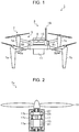
- FIG. 1 is a perspective view schematically illustrating a vertical takeoff and landing (VTOL) aircraft 1 according to an embodiment of the invention.
- the VTOL aircraft 1 according to this embodiment is a multicopter that can obtain lift (thrust) by using rotating wings, and the scale of the aircraft includes anything from an unmanned aircraft called a drone to a large-scale manned aircraft.
- the VTOL aircraft 1 includes a main unit 3, an arm unit 5, and a rotary wing unit 7.
- the main unit 3 includes a power source (battery) 9, a compartment 11, a central controller 13, and a receiver 15.
- the power source 9 supplies electric power to each of the units (e.g., the rotary wing unit 7 and the central controller 13) in the VTOL aircraft 1.
- the compartment 11 is a human-boardable section.
- the compartment 11 may be a luggage-loadable section.
- the compartment 11 is provided with an operation unit (not illustrated). An occupant (i.e., a pilot) in the compartment 11 maneuvers the VTOL aircraft 1 by operating the operation unit.
- the central controller 13 controls the rotary wing unit 7 based on an operation signal (i.e., a control signal) from the operation unit so as to control, for example, ascending, descending, hovering, and horizontal movement of the VTOL aircraft 1.
- an operation signal i.e., a control signal
- the VTOL aircraft 1 may be maneuvered based on a control signal transmitted from a remote location or may fly autonomously in accordance with a program input in advance.
- the receiver 15 receives a control signal transmitted from a transmitter (not illustrated) disposed at a remote location.
- the transmitter is for wireless maneuvering and is provided with an operation unit.
- the pilot maneuvers the VTOL aircraft 1 by operating the operation unit in the transmitter from a remote location.
- the central controller 13 controls the rotary wing unit 7 based on a control signal received by the receiver 15 so as to control, for example, ascending, descending, hovering, and horizontal movement of the VTOL aircraft 1.
- the VTOL aircraft 1 may fly autonomously based on a program stored in advance in a storage unit (not illustrated) of the central controller 13.
- the arm unit 5 includes a power supply line for supplying electric power to the rotary wing unit 7.
- the arm unit 5 includes a first arm 5a, a second arm 5b, a third arm 5c, and a fourth arm 5d.
- the rotary wing unit 7 includes a first rotary wing unit 7a, a second rotary wing unit 7b, a third rotary wing unit 7c, and a fourth rotary wing unit 7d.
- the first arm 5a has a first end coupled to the main unit 3 and a second end coupled to the first rotary wing unit 7a.
- the first arm 5a links the main unit 3 and the first rotary wing unit 7a, and supports the first rotary wing unit 7a.
- the second arm 5b has a first end coupled to the main unit 3 and a second end coupled to the second rotary wing unit 7b.
- the second arm 5b links the main unit 3 and the second rotary wing unit 7b, and supports the second rotary wing unit 7b.
- the third arm 5c has a first end coupled to the main unit 3 and a second end coupled to the third rotary wing unit 7c.
- the third arm 5c links the main unit 3 and the third rotary wing unit 7c, and supports the third rotary wing unit 7c.
- the fourth arm 5d has a first end coupled to the main unit 3 and a second end coupled to the fourth rotary wing unit 7d.
- the fourth arm 5d links the main unit 3 and the fourth rotary wing unit 7d, and supports the fourth rotary wing unit 7d.
- the first arm 5a and the first rotary wing unit 7a have configurations identical to those of the second arm 5b and the second rotary wing unit 7b, the third arm 5c and the third rotary wing unit 7c, and the fourth arm 5d and the fourth rotary wing unit 7d. Therefore, the configurations of the first arm 5a and the first rotary wing unit 7a will be described below as an example, whereas the descriptions regarding the configurations of the second arm 5b and the second rotary wing unit 7b, the third arm 5c and the third rotary wing unit 7c, and the fourth arm 5d and the fourth rotary wing unit 7d will be omitted.
- FIG. 2 illustrates the configuration of the first rotary wing unit 7a.
- the first rotary wing unit 7a includes a driving unit 17 and a propeller (i.e., a rotary wing) 19.
- the driving unit 17 rotates the propeller 19.
- the driving unit 17 includes a motor 17a and an electromagnetic brake 17b.
- the motor 17a includes a rotor 21 and a stator 23.
- the rotor 21 is provided with a permanent magnet
- the stator 23 is provided with a coil.
- electric current is applied to the coil of the stator 23, the rotor 21 provided with the permanent magnet rotates.
- the motor 17a also includes a shaft (i.e., a rotating shaft) 17c.
- the shaft 17c is attached to a rotational axis of the rotor 21.
- the shaft 17c rotates together with the rotor 21 about the rotational axis of the rotor 21.
- the shaft 17c may be integrated with the rotor 21 or may be separate from the rotor 21.
- the electromagnetic brake 17b is attached to the shaft 17c of the motor 17a.
- the electromagnetic brake 17b is a braking device that applies braking torque (i.e., a braking force) to the shaft 17c.
- the electromagnetic brake 17b has a configuration similar to that of the motor 17a.
- the electromagnetic brake 17b includes a rotor 25 and a stator 27.
- the rotor 25 is provided with a permanent magnet
- the stator 27 is provided with a coil.
- the rotor 25 is attached to the shaft 17c and rotates together with the shaft 17c about a rotational axis of the shaft 17c.
- the rotor 25 may be integrated with the shaft 17c or may be separate from the shaft 17c.
- the rotor 25 provided with the permanent magnet rotates, thus causing electric current to flow to the coil of the stator 27.
- the stator 27 applies braking torque to the rotor 25 in a non-contact fashion.
- the electromagnetic brake 17b functions as a non-contact braking device that applies braking torque to the shaft 17c (i.e., the rotor 25) when the shaft 17c rotates. Furthermore, in the electromagnetic brake 17b, electric current flows to the coil of the stator 27 when the shaft 17c rotates. Therefore, the electromagnetic brake 17b functions as a power generator when the shaft 17c rotates.
- the propeller 19 is attached to the shaft 17c of the motor 17a and rotates together with the shaft 17c about the rotational axis of the shaft 17c. Accordingly, the shaft 17c of the motor 17a also functions as a shaft of the propeller 19. The propeller 19 rotates with the same rotational speed as the rotational speed of the motor 17a. The propeller 19 converts the rotational force of the motor 17a into thrust (lift).
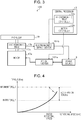
- FIG. 3 is a block diagram schematically illustrating the configuration of a rotary wing driving apparatus 100 according to this embodiment.
- the rotary wing driving apparatus 100 is provided in the VTOL aircraft 1.
- a solid arrow denotes the flow of electric power
- a dashed arrow denotes the flow of a control signal.
- the rotary wing driving apparatus 100 includes the power source 9, the central controller 13, the motor 17a, the electromagnetic brake 17b, the shaft 17c, the propeller 19, a motor inverter 101a, and an electromagnetic-brake inverter 101b.
- the power source 9 is coupled to the motor 17a via the motor inverter 101a.
- the power source 9 supplies electric power to the motor 17a via the motor inverter 101a.
- the power source 9 is also coupled to the electromagnetic brake 17b via the electromagnetic-brake inverter 101b.
- the power source 9 is supplied with (i.e., collects) electric power generated by the electromagnetic brake 17b via the electromagnetic-brake inverter 101b.
- the central controller 13 is constituted by a semiconductor integrated circuit including a central processing unit (CPU), a read-only memory (ROM) having a program stored therein, and a random access memory (RAM) as a work area, and controls the entire VTOL aircraft 1.
- the central controller 13 may serve also as a motor controller 13a and an electromagnetic brake controller 13b by operating in cooperation with a program.
- the motor controller 13a controls (a switching element of) the motor inverter 101a to control the rotational speed and the torque of the motor 17a (i.e., the propeller 19).
- the motor controller 13a controls the motor inverter 101a to control the electric current applied to the coil provided in the stator 23 (see FIG 2 ) and the frequency of the electric current, thereby controlling the rotational speed and the torque of the motor 17a.
- the motor controller 13a controls the rotational speed and the torque of the motor 17a based on the control signal mentioned above.
- the motor controller 13a controls the rotational speed and the torque of the propeller 19 to generate thrust (lift) for the VTOL aircraft 1.
- the electromagnetic brake controller 13b controls (a switching element of) the electromagnetic-brake inverter 101b to control the braking torque of the electromagnetic brake 17b. While applying the braking torque to the shaft 17c, the electromagnetic brake 17b converts the rotational force of the shaft 17c into electric power. The electromagnetic brake controller 13b controls the braking torque of the electromagnetic brake 17b to cause the electric power converted (generated) by the electromagnetic brake 17b to change.
- the electromagnetic brake controller 13b controls the electric power generated by the electromagnetic brake 17b.
- the electromagnetic brake controller 13b causes the power source 9 to store the electric power generated by the electromagnetic brake 17b.
- attitude-angle control of the aircraft body tends to become unstable during hovering.
- the VTOL aircraft 1 obtains lift by rotating the propeller 19 using the motor 17a.
- the lift includes a force for levitating the aircraft body and a force for stabilizing the attitude-angle control of the aircraft body relative to the external environment, such as wind.
- the torque of the motor 17a used for levitating the body of the VTOL aircraft 1 is called rated torque.
- the torque of the motor 17a used for stabilizing the attitude-angle control of the body of the VTOL aircraft 1 is called acceleration torque.
- FIG. 4 illustrates the characteristics of a commonly-used motor.
- the ordinate axis indicates the torque of the motor
- the abscissa axis indicates the rotational speed of the motor.
- the maximum torque of the motor is indicated by a single-dot chain line
- the torque used for actuating the propeller 19 is indicated by a solid line.
- the motor has a rated torque of 3.5 N ⁇ m during a rated operation and a rated rotational speed of 8000 rpm.
- the motor In order to perform (stable) attitude-angle control in view of the occupant's riding comfort, it is desirable that the motor normally have a 5 % control bandwidth and 5-Hz aircraft-direction control characteristics.
- the VTOL aircraft 1 desirably has an acceleration torque of 5.4 N ⁇ m for performing stable attitude-angle control using the motor alone.
- the motor desirably has a maximum torque of at least 8.9 N ⁇ m.
- the motor used in the related art has a maximum torque that is double or more the rated torque for performing stable attitude-angle control of the VTOL aircraft 1. Therefore, in the related art, the motor is increased in size for performing stable attitude-angle control of the VTOL aircraft 1.
- the rotary wing driving apparatus 100 includes the electromagnetic brake 17b and the electromagnetic brake controller 13b.
- the motor 17a desirably has a 5 % control bandwidth and 5-Hz aircraft-direction control characteristics.
- the motor 17a used desirably has a maximum torque that is double or more the rated torque, as mentioned above.
- the motor 17a and the electromagnetic brake 17b are combined, thereby ensuring a 5 % control bandwidth relative to an output (i.e., a target output) of the motor 17a and 5-Hz aircraft-direction control characteristics.
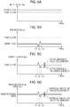
- FIG. 5A to FIG. 5D illustrate the relationship among the motor output of the motor 17a, the braking force of the electromagnetic brake 17b, and the propeller output and the propeller rotational speed of the propeller 19.
- the motor output of the motor used for levitating the body of the VTOL aircraft 1 i.e., the rated torque and the rated rotational speed illustrated in FIG. 4
- a target output i.e., the rated torque and the rated rotational speed illustrated in FIG. 4
- FIG. 5A illustrates a state where the motor 17a is outputting a motor output (i.e., an actual output) that is larger than the target output.
- a motor output i.e., an actual output
- FIG. 5B illustrates a state where the electromagnetic brake 17b is applying a braking force.
- FIG. 5C illustrates, as a propeller output, a combined output of the motor output of the motor 17a and the braking force of the electromagnetic brake 17b (i.e., motor output - braking force).
- the combined output may also be regarded as an actual output of the driving unit 17.
- FIG. 5D illustrates the propeller rotational speed when the propeller 19 is rotating with the propeller output illustrated in FIG. 5C .
- the motor 17a is capable of outputting an actual output that is larger than the target output by a predetermined amount.
- the motor 17a is outputting a fixed actual output.
- the electromagnetic brake 17b is applying a fixed braking force to the shaft 17c until a time point t1 is reached.
- the fixed braking force is substantially equal to a difference between the actual output of the motor 17a and the target output illustrated in FIG 5A .
- the electromagnetic brake 17b applies a small braking force smaller than the fixed braking force to the shaft 17c in a period from the time point t1 to a time point t2.
- the electromagnetic brake 17b applies a large braking force larger than the fixed braking force to the shaft 17c in a period from the time point t2 to a time point t3.
- the electromagnetic brake 17b applies the fixed braking force to the shaft 17c from the time point t3 and onward.
- the propeller output becomes a value obtained by subtracting the braking force of the electromagnetic brake 17b from the actual output of the motor 17a.
- the propeller output is a value obtained by subtracting the fixed braking force from the actual output. In this case, the propeller output is substantially equal to the target output.
- the propeller output is a value obtained by subtracting the small braking force from the actual output.
- the propeller output is a value larger than the target output by a variation in the small braking force.
- the propeller output is a value smaller than the target output by a variation in the large braking force.
- the electromagnetic brake controller 13b controls the braking force in a period from the time point t1 to the time point t3, thereby controlling the propeller output within a short period of time in a +5 % control bandwidth and a -5 % control bandwidth relative to the target output.
- the electromagnetic brake controller 13b controls the propeller output to an output larger than the target output by 5 % in half of the period between the time point t1 and the time point t2.
- the electromagnetic brake controller 13b controls the propeller output to an output smaller than the target output by 5 % in half of the period between the time point t2 and the time point t3.
- half of the period between the time point t1 and the time point t2 and half of the period between the time point t2 and the time point t3 are response time periods corresponding to the 5-Hz aircraft-direction control characteristics.
- the propeller rotational speed is a target rotational speed that is fixed in accordance with the propeller output.
- the propeller rotational speed is higher than the target rotational speed in accordance with the propeller output.
- the propeller rotational speed is lower than the target rotational speed in accordance with the propeller output.
- the electromagnetic brake controller 13b controls the braking force in the period from the time point t1 to the time point t3, thereby controlling the propeller rotational speed in the +5 % control bandwidth and the -5 % control bandwidth relative to the target rotational speed of the propeller 19. Furthermore, for example, the electromagnetic brake controller 13b controls the propeller rotational speed to a rotational speed higher than the target rotational speed by 5 % in half of the period between the time point t1 and the time point t2.
- the electromagnetic brake controller 13b controls the propeller rotational speed to a rotational speed lower than the target rotational speed by 5 % in half of the period between the time point t2 and the time point t3.
- half of the period between the time point t1 and the time point t2 and half of the period between the time point t2 and the time point t3 are response time periods corresponding to the 5-Hz aircraft-direction control characteristics.
- the rotary wing driving apparatus 100 can ensure the 5 % control bandwidth relative to the target output (target rotational speed) and the 5-Hz aircraft-direction control characteristics, as illustrated in FIG. 5C and FIG. 5D .
- the motor 17a is capable of outputting an actual output that is larger than the rated torque and the rated rotational speed (i.e., the target output) illustrated in FIG. 4 by the predetermined amount.
- the motor controller 13a controls the motor 17a such that the motor 17a outputs an actual output that is larger than the target output by the predetermined amount.
- the electromagnetic brake controller 13b controls the braking force applied to the shaft 17c of the motor 17a, thereby controlling the propeller output (i.e., the propeller rotational speed) with the 5 % control bandwidth relative to the target output (target rotational speed) and the 5-Hz aircraft-direction control characteristics.
- the rotary wing driving apparatus 100 includes the motor 17a capable of outputting an actual output that is larger than 3.5 N ⁇ m and 8000 rpm by the predetermined amount so as to ensure the 5 % control bandwidth.
- the motor 17a capable of outputting an actual output that is larger than 3.5 N ⁇ m and 8000 rpm by the predetermined amount is, for example, a motor with a maximum torque that is less than double the rated torque (3.5 N ⁇ m).
- the motor 17a used for performing stable attitude-angle control of the VTOL aircraft 1 is smaller than that in the related art (i.e., has a maximum torque that is less than double the rated torque). Therefore, the rotary wing driving apparatus 100 can suppress an increase in size of the motor 17a in the VTOL aircraft 1.
- the rotary wing driving apparatus 100 uses the electromagnetic brake 17b as a device for applying braking torque to the shaft 17c. Therefore, the rotary wing driving apparatus 100 can shorten the variation time (response) of the braking torque, as compared with a case where a hydraulic brake is used as a device for applying braking torque to the shaft 17c.
- the program in this case refers to a data processing unit described in any language and any description method.
- the electromagnetic brake controller 13b causes the power source 9 to store the electric power generated by the electromagnetic brake 17b.
- the electromagnetic brake controller 13b may be configured not to cause the power source 9 to store the electric power generated by the electromagnetic brake 17b.
- an increase in size of the motor can be suppressed.
Landscapes
- Engineering & Computer Science (AREA)
- Aviation & Aerospace Engineering (AREA)
- Mechanical Engineering (AREA)
- Power Engineering (AREA)
- Combustion & Propulsion (AREA)
- Chemical & Material Sciences (AREA)
- Remote Sensing (AREA)
- Sustainable Energy (AREA)
- Physics & Mathematics (AREA)
- Life Sciences & Earth Sciences (AREA)
- Sustainable Development (AREA)
- Electromagnetism (AREA)
- Transportation (AREA)
- Control Of Multiple Motors (AREA)
- General Engineering & Computer Science (AREA)
- Braking Arrangements (AREA)
- Toys (AREA)
- Connection Of Motors, Electrical Generators, Mechanical Devices, And The Like (AREA)
Abstract
Description
- The present application claims priority from Japanese Patent Application No.
2019-002133 filed on January 9, 2019 - The invention relates to rotary wing driving apparatuses.
- Japanese Unexamined Patent Application Publication
JP H4-173 497 A - An aspect of the invention provides a rotary wing driving apparatus including a motor, a rotary wing, and an electromagnetic brake. The rotary wing is attached to a shaft of the motor. The electromagnetic brake is attached to the shaft of the motor.
- The accompanying drawings are included to provide a further understanding of the invention and are incorporated in and constitute a part of this specification. The drawings illustrate example embodiments and, together with the specification, serve to explain the principles of the invention.
- FIG. 1
- is a perspective view schematically illustrating a VTOL aircraft according to an embodiment of the invention;
- FIG. 2
- illustrates the configuration of a first rotary wing unit;
- FIG. 3
- is a block diagram schematically illustrating the configuration of a rotary wing driving apparatus according to the embodiment of the invention;
- FIG. 4
- illustrates the characteristics of a commonly-used motor; and
- FIG. 5A to FIG 5D
- illustrate the relationship among a motor output of a motor, a braking force of an electromagnetic brake, and a propeller output and a propeller rotational speed of a propeller,
- FIG. 5A
- illustrating a state where the motor is outputting a motor output (i.e., an actual output) that is larger than a target output,
- FIG. 5B
- illustrating a state where the electromagnetic brake is applying a braking force,
- FIG. 5C
- illustrating, as a propeller output, a combined output of the motor output of the motor and the braking force of the electromagnetic brake (i.e., motor output - braking force),
- FIG. 5D
- illustrating the propeller rotational speed when the propeller is rotating with the propeller output illustrated in
FIG. 5C . - In the following, an embodiment of the invention is described in detail with reference to the accompanying drawings. Note that the following description is directed to an illustrative example of the invention and not to be construed as limiting to the invention. Factors including, without limitation, numerical values, shapes, materials, components, positions of the components, and how the components are coupled to each other are illustrative only and not to be construed as limiting to the invention.
- Further, elements in the following example embodiment which are not recited in a most-generic independent claim of the invention are optional and may be provided on an as-needed basis. The drawings are schematic and are not intended to be drawn to scale. Throughout the present specification and the drawings, elements having substantially the same function and configuration are denoted with the same numerals to avoid any redundant description.
- With regard to a VTOL aircraft, attitude-angle control of the aircraft body tends to become unstable during hovering. Thus, it is desirable that the VTOL aircraft perform stable attitude-angle control. In order to perform stable attitude-angle control, it is desirable that the VTOL aircraft constantly have sufficient acceleration performance.
- If the VTOL aircraft is configured to rotate a propeller by using a motor, it is desirable that the VTOL aircraft include a motor having a maximum torque that is double or more the rated torque (e.g., torque used for levitating the aircraft body) so as to perform the attitude-angle control stably. Therefore, in order to perform stable attitude-angle control, the motor in the VTOL aircraft is to be increased in size.
- It is desirable to provide a rotary wing driving apparatus that can suppress an increase in size of the motor.
-
FIG. 1 is a perspective view schematically illustrating a vertical takeoff and landing (VTOL) aircraft 1 according to an embodiment of the invention. The VTOL aircraft 1 according to this embodiment is a multicopter that can obtain lift (thrust) by using rotating wings, and the scale of the aircraft includes anything from an unmanned aircraft called a drone to a large-scale manned aircraft. The VTOL aircraft 1 includes amain unit 3, anarm unit 5, and arotary wing unit 7. Themain unit 3 includes a power source (battery) 9, acompartment 11, acentral controller 13, and areceiver 15. - The
power source 9 supplies electric power to each of the units (e.g., therotary wing unit 7 and the central controller 13) in the VTOL aircraft 1. In this embodiment, thecompartment 11 is a human-boardable section. Alternatively, thecompartment 11 may be a luggage-loadable section. Thecompartment 11 is provided with an operation unit (not illustrated). An occupant (i.e., a pilot) in thecompartment 11 maneuvers the VTOL aircraft 1 by operating the operation unit. Thecentral controller 13 controls therotary wing unit 7 based on an operation signal (i.e., a control signal) from the operation unit so as to control, for example, ascending, descending, hovering, and horizontal movement of the VTOL aircraft 1. - As an alternative to this embodiment where the occupant (i.e., the pilot) who has boarded the
compartment 11 maneuvers the VTOL aircraft 1, the VTOL aircraft 1 may be maneuvered based on a control signal transmitted from a remote location or may fly autonomously in accordance with a program input in advance. For example, thereceiver 15 receives a control signal transmitted from a transmitter (not illustrated) disposed at a remote location. - For example, the transmitter is for wireless maneuvering and is provided with an operation unit. The pilot maneuvers the VTOL aircraft 1 by operating the operation unit in the transmitter from a remote location. The
central controller 13 controls therotary wing unit 7 based on a control signal received by thereceiver 15 so as to control, for example, ascending, descending, hovering, and horizontal movement of the VTOL aircraft 1. As another alternative, the VTOL aircraft 1 may fly autonomously based on a program stored in advance in a storage unit (not illustrated) of thecentral controller 13. - The
arm unit 5 includes a power supply line for supplying electric power to therotary wing unit 7. Thearm unit 5 includes a first arm 5a, asecond arm 5b, athird arm 5c, and a fourth arm 5d. Therotary wing unit 7 includes a firstrotary wing unit 7a, a secondrotary wing unit 7b, a thirdrotary wing unit 7c, and a fourthrotary wing unit 7d. - The first arm 5a has a first end coupled to the
main unit 3 and a second end coupled to the firstrotary wing unit 7a. The first arm 5a links themain unit 3 and the firstrotary wing unit 7a, and supports the firstrotary wing unit 7a. Thesecond arm 5b has a first end coupled to themain unit 3 and a second end coupled to the secondrotary wing unit 7b. Thesecond arm 5b links themain unit 3 and the secondrotary wing unit 7b, and supports the secondrotary wing unit 7b. - The
third arm 5c has a first end coupled to themain unit 3 and a second end coupled to the thirdrotary wing unit 7c. Thethird arm 5c links themain unit 3 and the thirdrotary wing unit 7c, and supports the thirdrotary wing unit 7c. The fourth arm 5d has a first end coupled to themain unit 3 and a second end coupled to the fourthrotary wing unit 7d. The fourth arm 5d links themain unit 3 and the fourthrotary wing unit 7d, and supports the fourthrotary wing unit 7d. - The first arm 5a and the first
rotary wing unit 7a have configurations identical to those of thesecond arm 5b and the secondrotary wing unit 7b, thethird arm 5c and the thirdrotary wing unit 7c, and the fourth arm 5d and the fourthrotary wing unit 7d. Therefore, the configurations of the first arm 5a and the firstrotary wing unit 7a will be described below as an example, whereas the descriptions regarding the configurations of thesecond arm 5b and the secondrotary wing unit 7b, thethird arm 5c and the thirdrotary wing unit 7c, and the fourth arm 5d and the fourthrotary wing unit 7d will be omitted. -
FIG. 2 illustrates the configuration of the firstrotary wing unit 7a. As illustrated inFIG. 2 , the firstrotary wing unit 7a includes a drivingunit 17 and a propeller (i.e., a rotary wing) 19. The drivingunit 17 rotates thepropeller 19. The drivingunit 17 includes amotor 17a and anelectromagnetic brake 17b. - The
motor 17a includes arotor 21 and astator 23. In themotor 17a, for example, therotor 21 is provided with a permanent magnet, and thestator 23 is provided with a coil. When electric current is applied to the coil of thestator 23, therotor 21 provided with the permanent magnet rotates. - The
motor 17a also includes a shaft (i.e., a rotating shaft) 17c. Theshaft 17c is attached to a rotational axis of therotor 21. Theshaft 17c rotates together with therotor 21 about the rotational axis of therotor 21. Theshaft 17c may be integrated with therotor 21 or may be separate from therotor 21. - The
electromagnetic brake 17b is attached to theshaft 17c of themotor 17a. Theelectromagnetic brake 17b is a braking device that applies braking torque (i.e., a braking force) to theshaft 17c. Theelectromagnetic brake 17b has a configuration similar to that of themotor 17a. In other words, theelectromagnetic brake 17b includes arotor 25 and astator 27. In theelectromagnetic brake 17b, for example, therotor 25 is provided with a permanent magnet, and thestator 27 is provided with a coil. - The
rotor 25 is attached to theshaft 17c and rotates together with theshaft 17c about a rotational axis of theshaft 17c. Therotor 25 may be integrated with theshaft 17c or may be separate from theshaft 17c. When theshaft 17c rotates, therotor 25 provided with the permanent magnet rotates, thus causing electric current to flow to the coil of thestator 27. In this case, thestator 27 applies braking torque to therotor 25 in a non-contact fashion. - Accordingly, the
electromagnetic brake 17b functions as a non-contact braking device that applies braking torque to theshaft 17c (i.e., the rotor 25) when theshaft 17c rotates. Furthermore, in theelectromagnetic brake 17b, electric current flows to the coil of thestator 27 when theshaft 17c rotates. Therefore, theelectromagnetic brake 17b functions as a power generator when theshaft 17c rotates. - The
propeller 19 is attached to theshaft 17c of themotor 17a and rotates together with theshaft 17c about the rotational axis of theshaft 17c. Accordingly, theshaft 17c of themotor 17a also functions as a shaft of thepropeller 19. Thepropeller 19 rotates with the same rotational speed as the rotational speed of themotor 17a. Thepropeller 19 converts the rotational force of themotor 17a into thrust (lift). -
FIG. 3 is a block diagram schematically illustrating the configuration of a rotarywing driving apparatus 100 according to this embodiment. The rotarywing driving apparatus 100 is provided in the VTOL aircraft 1. InFIG. 3 , a solid arrow denotes the flow of electric power, and a dashed arrow denotes the flow of a control signal. As illustrated inFIG. 3 , the rotarywing driving apparatus 100 includes thepower source 9, thecentral controller 13, themotor 17a, theelectromagnetic brake 17b, theshaft 17c, thepropeller 19, a motor inverter 101a, and an electromagnetic-brake inverter 101b. - The
power source 9 is coupled to themotor 17a via the motor inverter 101a. Thepower source 9 supplies electric power to themotor 17a via the motor inverter 101a. Thepower source 9 is also coupled to theelectromagnetic brake 17b via the electromagnetic-brake inverter 101b. Thepower source 9 is supplied with (i.e., collects) electric power generated by theelectromagnetic brake 17b via the electromagnetic-brake inverter 101b. - The
central controller 13 is constituted by a semiconductor integrated circuit including a central processing unit (CPU), a read-only memory (ROM) having a program stored therein, and a random access memory (RAM) as a work area, and controls the entire VTOL aircraft 1. Thecentral controller 13 may serve also as amotor controller 13a and anelectromagnetic brake controller 13b by operating in cooperation with a program. - The
motor controller 13a controls (a switching element of) the motor inverter 101a to control the rotational speed and the torque of themotor 17a (i.e., the propeller 19). Themotor controller 13a controls the motor inverter 101a to control the electric current applied to the coil provided in the stator 23 (seeFIG 2 ) and the frequency of the electric current, thereby controlling the rotational speed and the torque of themotor 17a. For example, themotor controller 13a controls the rotational speed and the torque of themotor 17a based on the control signal mentioned above. Themotor controller 13a controls the rotational speed and the torque of thepropeller 19 to generate thrust (lift) for the VTOL aircraft 1. - The
electromagnetic brake controller 13b controls (a switching element of) the electromagnetic-brake inverter 101b to control the braking torque of theelectromagnetic brake 17b. While applying the braking torque to theshaft 17c, theelectromagnetic brake 17b converts the rotational force of theshaft 17c into electric power. Theelectromagnetic brake controller 13b controls the braking torque of theelectromagnetic brake 17b to cause the electric power converted (generated) by theelectromagnetic brake 17b to change. - In other words, the
electromagnetic brake controller 13b controls the electric power generated by theelectromagnetic brake 17b. Theelectromagnetic brake controller 13b causes thepower source 9 to store the electric power generated by theelectromagnetic brake 17b. - With regard to the VTOL aircraft 1, attitude-angle control of the aircraft body tends to become unstable during hovering. Thus, it is desirable that the VTOL aircraft 1 perform stable attitude-angle control. In order to perform stable attitude-angle control, it is desirable that the VTOL aircraft 1 constantly have sufficient acceleration performance.
- The VTOL aircraft 1 obtains lift by rotating the
propeller 19 using themotor 17a. The lift includes a force for levitating the aircraft body and a force for stabilizing the attitude-angle control of the aircraft body relative to the external environment, such as wind. The torque of themotor 17a used for levitating the body of the VTOL aircraft 1 is called rated torque. The torque of themotor 17a used for stabilizing the attitude-angle control of the body of the VTOL aircraft 1 is called acceleration torque. -
FIG. 4 illustrates the characteristics of a commonly-used motor. InFIG. 4 , the ordinate axis indicates the torque of the motor, and the abscissa axis indicates the rotational speed of the motor. InFIG. 4 , the maximum torque of the motor is indicated by a single-dot chain line, and the torque used for actuating the propeller 19 (referred to as "propeller absorption torque" hereinafter) is indicated by a solid line. - For example, it is assumed that the motor has a rated torque of 3.5 N·m during a rated operation and a rated rotational speed of 8000 rpm. In order to perform (stable) attitude-angle control in view of the occupant's riding comfort, it is desirable that the motor normally have a 5 % control bandwidth and 5-Hz aircraft-direction control characteristics. In that case, the VTOL aircraft 1 desirably has an acceleration torque of 5.4 N·m for performing stable attitude-angle control using the motor alone. In other words, the motor desirably has a maximum torque of at least 8.9 N·m.
- Accordingly, the motor used in the related art has a maximum torque that is double or more the rated torque for performing stable attitude-angle control of the VTOL aircraft 1. Therefore, in the related art, the motor is increased in size for performing stable attitude-angle control of the VTOL aircraft 1.
- In order to suppress such an increase in size of the motor, the rotary
wing driving apparatus 100 according to this embodiment includes theelectromagnetic brake 17b and theelectromagnetic brake controller 13b. As mentioned above, in order to perform (stable) attitude-angle control, themotor 17a desirably has a 5 % control bandwidth and 5-Hz aircraft-direction control characteristics. - However, for example, if a 5 % control bandwidth and 5-Hz aircraft-direction control characteristics are to be ensured by the
motor 17a alone during a rated operation, themotor 17a used desirably has a maximum torque that is double or more the rated torque, as mentioned above. Thus, in this embodiment, themotor 17a and theelectromagnetic brake 17b are combined, thereby ensuring a 5 % control bandwidth relative to an output (i.e., a target output) of themotor 17a and 5-Hz aircraft-direction control characteristics. -
FIG. 5A to FIG. 5D illustrate the relationship among the motor output of themotor 17a, the braking force of theelectromagnetic brake 17b, and the propeller output and the propeller rotational speed of thepropeller 19. InFIG. 5A to FIG. 5D , the motor output of the motor used for levitating the body of the VTOL aircraft 1 (i.e., the rated torque and the rated rotational speed illustrated inFIG. 4 ) is defined as a target output. -
FIG. 5A illustrates a state where themotor 17a is outputting a motor output (i.e., an actual output) that is larger than the target output. -
FIG. 5B illustrates a state where theelectromagnetic brake 17b is applying a braking force. -
FIG. 5C illustrates, as a propeller output, a combined output of the motor output of themotor 17a and the braking force of theelectromagnetic brake 17b (i.e., motor output - braking force). The combined output may also be regarded as an actual output of the drivingunit 17. -
FIG. 5D illustrates the propeller rotational speed when thepropeller 19 is rotating with the propeller output illustrated inFIG. 5C . - As illustrated in
FIG. 5A , themotor 17a is capable of outputting an actual output that is larger than the target output by a predetermined amount. InFIG 5A , themotor 17a is outputting a fixed actual output. As illustrated inFIG. 5B , theelectromagnetic brake 17b is applying a fixed braking force to theshaft 17c until a time point t1 is reached. For example, the fixed braking force is substantially equal to a difference between the actual output of themotor 17a and the target output illustrated inFIG 5A . - The
electromagnetic brake 17b applies a small braking force smaller than the fixed braking force to theshaft 17c in a period from the time point t1 to a time point t2. Theelectromagnetic brake 17b applies a large braking force larger than the fixed braking force to theshaft 17c in a period from the time point t2 to a time point t3. Theelectromagnetic brake 17b applies the fixed braking force to theshaft 17c from the time point t3 and onward. - As illustrated in
FIG. 5C , the propeller output becomes a value obtained by subtracting the braking force of theelectromagnetic brake 17b from the actual output of themotor 17a. In detail, until the time point t1 is reached, the propeller output is a value obtained by subtracting the fixed braking force from the actual output. In this case, the propeller output is substantially equal to the target output. - In the period from the time point t1 to the time point t2, the propeller output is a value obtained by subtracting the small braking force from the actual output. In this case, the propeller output is a value larger than the target output by a variation in the small braking force. In the period from the time point t2 to the time point t3, the propeller output is a value smaller than the target output by a variation in the large braking force.
- As illustrated in
FIG. 5C , theelectromagnetic brake controller 13b controls the braking force in a period from the time point t1 to the time point t3, thereby controlling the propeller output within a short period of time in a +5 % control bandwidth and a -5 % control bandwidth relative to the target output. - Furthermore, for example, the
electromagnetic brake controller 13b controls the propeller output to an output larger than the target output by 5 % in half of the period between the time point t1 and the time point t2. Likewise, theelectromagnetic brake controller 13b controls the propeller output to an output smaller than the target output by 5 % in half of the period between the time point t2 and the time point t3. In this case, half of the period between the time point t1 and the time point t2 and half of the period between the time point t2 and the time point t3 are response time periods corresponding to the 5-Hz aircraft-direction control characteristics. - As illustrated in
FIG. 5D , until the time point t1 is reached, the propeller rotational speed is a target rotational speed that is fixed in accordance with the propeller output. In the period from the time point t1 to the time point t2, the propeller rotational speed is higher than the target rotational speed in accordance with the propeller output. In the period from the time point t2 to the time point t3, the propeller rotational speed is lower than the target rotational speed in accordance with the propeller output. - As illustrated in
FIG. 5D , theelectromagnetic brake controller 13b controls the braking force in the period from the time point t1 to the time point t3, thereby controlling the propeller rotational speed in the +5 % control bandwidth and the -5 % control bandwidth relative to the target rotational speed of thepropeller 19. Furthermore, for example, theelectromagnetic brake controller 13b controls the propeller rotational speed to a rotational speed higher than the target rotational speed by 5 % in half of the period between the time point t1 and the time point t2. - Likewise, the
electromagnetic brake controller 13b controls the propeller rotational speed to a rotational speed lower than the target rotational speed by 5 % in half of the period between the time point t2 and the time point t3. In this case, half of the period between the time point t1 and the time point t2 and half of the period between the time point t2 and the time point t3 are response time periods corresponding to the 5-Hz aircraft-direction control characteristics. - By combining the motor output of the
motor 17a and the braking force of theelectromagnetic brake 17b in this manner, the rotarywing driving apparatus 100 can ensure the 5 % control bandwidth relative to the target output (target rotational speed) and the 5-Hz aircraft-direction control characteristics, as illustrated inFIG. 5C and FIG. 5D . - In this embodiment, the
motor 17a is capable of outputting an actual output that is larger than the rated torque and the rated rotational speed (i.e., the target output) illustrated inFIG. 4 by the predetermined amount. During the rated operation of themotor 17a, themotor controller 13a controls themotor 17a such that themotor 17a outputs an actual output that is larger than the target output by the predetermined amount. - In this case, the
electromagnetic brake controller 13b controls the braking force applied to theshaft 17c of themotor 17a, thereby controlling the propeller output (i.e., the propeller rotational speed) with the 5 % control bandwidth relative to the target output (target rotational speed) and the 5-Hz aircraft-direction control characteristics. - For example, if the target torque (i.e., the rated torque illustrated in
FIG. 4 ) in the target output is 3.5 N·m and the target rotational speed (i.e., the rated rotational speed illustrated inFIG. 4 ) is 8000 rpm, the rotarywing driving apparatus 100 includes themotor 17a capable of outputting an actual output that is larger than 3.5 N·m and 8000 rpm by the predetermined amount so as to ensure the 5 % control bandwidth. - The
motor 17a capable of outputting an actual output that is larger than 3.5 N·m and 8000 rpm by the predetermined amount is, for example, a motor with a maximum torque that is less than double the rated torque (3.5 N·m). - Accordingly, in the rotary
wing driving apparatus 100 according to this embodiment, themotor 17a used for performing stable attitude-angle control of the VTOL aircraft 1 is smaller than that in the related art (i.e., has a maximum torque that is less than double the rated torque). Therefore, the rotarywing driving apparatus 100 can suppress an increase in size of themotor 17a in the VTOL aircraft 1. - Moreover, the rotary
wing driving apparatus 100 uses theelectromagnetic brake 17b as a device for applying braking torque to theshaft 17c. Therefore, the rotarywing driving apparatus 100 can shorten the variation time (response) of the braking torque, as compared with a case where a hydraulic brake is used as a device for applying braking torque to theshaft 17c. - Although an embodiment of the present invention has been described above with reference to the appended drawings, the present invention is not limited to the embodiment. It is obvious to a person skilled in the art that various modifications and alterations are possible within the scope defined in the claims, and it is to be understood that such modifications and alterations belong to the technical scope of the invention.
- For example, there are also provided a program for causing a computer to function as the
central controller 13 of the rotarywing driving apparatus 100 and a storage medium, such as any one of a computer-readable flexible disk, magneto-optical disk, ROM, compact disc (CD), digital versatile disc (DVD), or Blu-ray disc (BD), having the program stored therein. The program in this case refers to a data processing unit described in any language and any description method. - In this embodiment, the
electromagnetic brake controller 13b causes thepower source 9 to store the electric power generated by theelectromagnetic brake 17b. Alternatively, theelectromagnetic brake controller 13b may be configured not to cause thepower source 9 to store the electric power generated by theelectromagnetic brake 17b. - According to an embodiment of the present invention, an increase in size of the motor can be suppressed.
-
- 1
- VTOL aircraft
- 3
- main unit
- 5
- arm unit
- 5a
- first arm
- 5b
- second arm
- 5c
- third arm
- 5d
- fourth arm
- 7
- rotary wing unit
- 7a
- first rotary wing unit
- 7b
- second rotary wing unit
- 7c
- third rotary wing unit
- 7d
- fourth rotary wing unit
- 9
- power source
- 11
- compartment
- 13
- central controller
- 13a
- motor controller
- 13b
- electromagnetic brake controller
- 15
- receiver
- 17
- driving unit
- 17a
- motor
- 17b
- electromagnetic brake
- 19
- propeller (rotary wing)
- 21
- rotor
- 23
- stator
- 25
- rotor
- 27
- stator
- 100
- rotary wing driving apparatus
- 101a
- motor inverter
- 101b
- electromagnetic-brake inverter
Claims (3)
- A rotary wing driving apparatus (100) comprising:- a motor (17a);- a rotary wing (19) attached to a shaft (17c) of the motor (17a); and- an electromagnetic brake (17b) attached to the shaft (17c) of the motor (17a).
- The rotary wing driving apparatus (100) according to Claim 1,
further comprising:an electromagnetic brake controller (13b) configured to control braking torque of the electromagnetic brake (17b). - The rotary wing driving apparatus (100) according to Claim 2,
further comprising:- a power source (9),wherein the electromagnetic brake controller (13b) is configured to cause the power source (9) to store electric power generated by the electromagnetic brake (17b).
Applications Claiming Priority (1)
| Application Number | Priority Date | Filing Date | Title |
|---|---|---|---|
| JP2019002133A JP7185536B2 (en) | 2019-01-09 | 2019-01-09 | rotor drive |
Publications (2)
| Publication Number | Publication Date |
|---|---|
| EP3680171A1 true EP3680171A1 (en) | 2020-07-15 |
| EP3680171B1 EP3680171B1 (en) | 2022-06-08 |
Family
ID=68806605
Family Applications (1)
| Application Number | Title | Priority Date | Filing Date |
|---|---|---|---|
| EP19213731.3A Active EP3680171B1 (en) | 2019-01-09 | 2019-12-05 | Rotary wing driving apparatus |
Country Status (3)
| Country | Link |
|---|---|
| US (1) | US11502577B2 (en) |
| EP (1) | EP3680171B1 (en) |
| JP (1) | JP7185536B2 (en) |
Families Citing this family (1)
| Publication number | Priority date | Publication date | Assignee | Title |
|---|---|---|---|---|
| JP2024068590A (en) | 2022-11-08 | 2024-05-20 | 株式会社Subaru | Rotorcraft |
Citations (6)
| Publication number | Priority date | Publication date | Assignee | Title |
|---|---|---|---|---|
| US2408683A (en) * | 1942-02-19 | 1946-10-01 | Rotol Ltd | Speed-control and synchronizing device |
| FR1006502A (en) * | 1948-01-24 | 1952-04-24 | Helicopter training | |
| JPH04173497A (en) | 1990-11-05 | 1992-06-22 | Haruo Sukai | Flying body |
| WO2016053408A1 (en) * | 2014-10-01 | 2016-04-07 | Sikorsky Aircraft Corporation | Acoustic signature variation of aircraft utilizing a clutch |
| CN106516128B (en) * | 2016-09-28 | 2018-08-28 | 南京航空航天大学 | A kind of electromagnetism multi-rotor aerocraft and control method based on turbogenerator |
| WO2019079688A1 (en) * | 2017-10-19 | 2019-04-25 | Uvionix Aerospace Corporation | Unmanned aerial vehicle and propulsion system for an unmanned aerial vehicle |
Family Cites Families (27)
| Publication number | Priority date | Publication date | Assignee | Title |
|---|---|---|---|---|
| US4676331A (en) * | 1984-12-20 | 1987-06-30 | Kabushiki Kaisha Toyoda Jidoshokki Seisakusho | Torque detecting apparatus for electrical power steering system |
| JPH0662093B2 (en) * | 1985-03-29 | 1994-08-17 | 豊田工機株式会社 | Electric power steering device |
| JPS621690A (en) * | 1985-06-27 | 1987-01-07 | Fukashi Uragami | Variable pitch propeller |
| US5047700A (en) * | 1988-03-23 | 1991-09-10 | The United States Of America As Represented By The Administrator Of The National Aeronautics And Space Administration | Universal computer control system for motors |
| JP3675692B2 (en) * | 2000-03-17 | 2005-07-27 | 光洋精工株式会社 | Electric power steering device |
| JP2001354154A (en) * | 2000-04-13 | 2001-12-25 | Honda Motor Co Ltd | Rear wheel steering device |
| US6547029B2 (en) * | 2001-09-10 | 2003-04-15 | Trw Inc. | Vehicle steering apparatus |
| DE112005003551B4 (en) * | 2005-04-22 | 2019-08-08 | Harmonic Drive Systems Inc. | Motor with built-in electromagnetic brake |
| JP4457156B2 (en) * | 2008-03-31 | 2010-04-28 | 山洋電気株式会社 | Motor with electromagnetic brake |
| DE102009026626A1 (en) * | 2009-06-02 | 2010-12-09 | Zf Friedrichshafen Ag | Clutch or brake in or on a gearbox |
| JP2012122574A (en) * | 2010-12-10 | 2012-06-28 | Hitachi Industrial Equipment Systems Co Ltd | Electromagnetic brake and electric motor |
| DE112013003825T5 (en) * | 2012-08-01 | 2015-04-30 | Honda Motor Co., Ltd. | drive system |
| WO2014159996A1 (en) * | 2013-03-14 | 2014-10-02 | Crown Equipment Corporation | Electrical steering assist features for materials handling vehicles |
| US20170008403A1 (en) * | 2015-05-26 | 2017-01-12 | Reza Yazdanpanah | Self-exicited and controllable hybrid electromagnetic braking (heb) system |
| JP6226914B2 (en) * | 2015-06-12 | 2017-11-08 | ファナック株式会社 | Servo motor stop control device that controls and stops the servo motor during an emergency stop |
| JP6301901B2 (en) * | 2015-12-15 | 2018-03-28 | トヨタ自動車株式会社 | Motor with electromagnetic brake |
| JP6325586B2 (en) * | 2016-02-18 | 2018-05-16 | トヨタ自動車株式会社 | Motor drive unit |
| US9663236B1 (en) * | 2016-03-28 | 2017-05-30 | Amazon Technologies, Inc. | Selectively thrusting propulsion units for aerial vehicles |
| CN105946549B (en) * | 2016-05-27 | 2018-03-23 | 浙江联宜电机有限公司 | Electric wheel hub and driving wheel |
| WO2018193522A1 (en) * | 2017-04-18 | 2018-10-25 | インダストリーネットワーク株式会社 | Propeller aircraft |
| JP2019031194A (en) * | 2017-08-08 | 2019-02-28 | 株式会社東芝 | Flight apparatus, installation method of installation object, and installation mechanism |
| US11804752B2 (en) * | 2018-01-12 | 2023-10-31 | Sew-Eurodrive Gmbh & Co. Kg | Drive, comprising an electric motor with a brake, a fan cowl, and a rod for manually actuating the brake, and process for manufacturing a drive |
| JP6538951B1 (en) * | 2018-12-06 | 2019-07-03 | 株式会社ショーワ | Reaction force generating device and steering device |
| US11025133B2 (en) * | 2019-02-20 | 2021-06-01 | Dana Automotive Systems Group, Llc | Electric motor brake |
| US12068660B2 (en) * | 2019-04-18 | 2024-08-20 | Parker-Hannifin Corporation | Electric motor |
| WO2021044528A1 (en) * | 2019-09-03 | 2021-03-11 | 楽天株式会社 | Uncrewed flight device, package-dropping device, and package-conveying method |
| JP7473320B2 (en) * | 2019-10-29 | 2024-04-23 | ファナック株式会社 | Electromagnetic brake for electric motor |
-
2019
- 2019-01-09 JP JP2019002133A patent/JP7185536B2/en active Active
- 2019-12-05 EP EP19213731.3A patent/EP3680171B1/en active Active
- 2019-12-31 US US16/731,929 patent/US11502577B2/en active Active
Patent Citations (6)
| Publication number | Priority date | Publication date | Assignee | Title |
|---|---|---|---|---|
| US2408683A (en) * | 1942-02-19 | 1946-10-01 | Rotol Ltd | Speed-control and synchronizing device |
| FR1006502A (en) * | 1948-01-24 | 1952-04-24 | Helicopter training | |
| JPH04173497A (en) | 1990-11-05 | 1992-06-22 | Haruo Sukai | Flying body |
| WO2016053408A1 (en) * | 2014-10-01 | 2016-04-07 | Sikorsky Aircraft Corporation | Acoustic signature variation of aircraft utilizing a clutch |
| CN106516128B (en) * | 2016-09-28 | 2018-08-28 | 南京航空航天大学 | A kind of electromagnetism multi-rotor aerocraft and control method based on turbogenerator |
| WO2019079688A1 (en) * | 2017-10-19 | 2019-04-25 | Uvionix Aerospace Corporation | Unmanned aerial vehicle and propulsion system for an unmanned aerial vehicle |
Also Published As
| Publication number | Publication date |
|---|---|
| JP7185536B2 (en) | 2022-12-07 |
| JP2020111124A (en) | 2020-07-27 |
| EP3680171B1 (en) | 2022-06-08 |
| US20200220428A1 (en) | 2020-07-09 |
| US11502577B2 (en) | 2022-11-15 |
Similar Documents
| Publication | Publication Date | Title |
|---|---|---|
| RU2403180C2 (en) | Method and device for braking and manoeuvring | |
| US10099794B2 (en) | Vertical take-off and landing aircraft using hybrid-electric propulsion system | |
| US20130264412A1 (en) | Rotary wing aircraft having a tail rotor, and a method of optimizing the operation of a tail rotor | |
| CN107399427B (en) | Rotary inerter and method for damping an actuator | |
| EP2865598B1 (en) | Aircraft electric motor system | |
| US20190084684A1 (en) | Hybrid aircraft | |
| EP2757040B1 (en) | System and method of harvesting power with a rotor hub damper | |
| US20190118941A1 (en) | Unmanned aerial vehicle and propulsion system for an unmanned aerial vehicle | |
| US20090236468A1 (en) | Dual frequency hub mounted vibration suppressor system | |
| US12509238B2 (en) | Electric aircraft and method for controlling aerodynamic performance thereof including distribution of lift in a wing | |
| KR102112290B1 (en) | Method and system for controlling autorotation of tilt-rotor type aircraft | |
| EP3680171B1 (en) | Rotary wing driving apparatus | |
| US20180022448A1 (en) | Active rotor damping system | |
| US12377998B2 (en) | Power supply system of vertical take-off and landing aircraft | |
| US20250051024A1 (en) | Flight control device, computer readable medium, and flight control method | |
| EP3919375B1 (en) | Distributed propulsion with thermal management | |
| JP2023104324A (en) | Control device for vertical take-off and landing aircraft | |
| US12515790B2 (en) | Systems and methods for vertical takeoff and landing vehicle with stator stabilization | |
| KR102137778B1 (en) | Regenerative braking system | |
| EP3667874B1 (en) | Electric propulsion system | |
| WO2024241771A1 (en) | Propulsion device, propulsion control device, and propulsion control program | |
| JP7580355B2 (en) | Aircraft Propulsion Systems | |
| JP7201010B2 (en) | ELECTRIC ACTUATOR DEVICE AND DRIVING METHOD FOR AIRCRAFT | |
| JP2022186353A (en) | Flight vehicle | |
| US20230099869A1 (en) | Propulsion system of aircraft |
Legal Events
| Date | Code | Title | Description |
|---|---|---|---|
| PUAI | Public reference made under article 153(3) epc to a published international application that has entered the european phase |
Free format text: ORIGINAL CODE: 0009012 |
|
| STAA | Information on the status of an ep patent application or granted ep patent |
Free format text: STATUS: THE APPLICATION HAS BEEN PUBLISHED |
|
| AK | Designated contracting states |
Kind code of ref document: A1 Designated state(s): AL AT BE BG CH CY CZ DE DK EE ES FI FR GB GR HR HU IE IS IT LI LT LU LV MC MK MT NL NO PL PT RO RS SE SI SK SM TR |
|
| AX | Request for extension of the european patent |
Extension state: BA ME |
|
| STAA | Information on the status of an ep patent application or granted ep patent |
Free format text: STATUS: REQUEST FOR EXAMINATION WAS MADE |
|
| 17P | Request for examination filed |
Effective date: 20210107 |
|
| RBV | Designated contracting states (corrected) |
Designated state(s): AL AT BE BG CH CY CZ DE DK EE ES FI FR GB GR HR HU IE IS IT LI LT LU LV MC MK MT NL NO PL PT RO RS SE SI SK SM TR |
|
| GRAP | Despatch of communication of intention to grant a patent |
Free format text: ORIGINAL CODE: EPIDOSNIGR1 |
|
| STAA | Information on the status of an ep patent application or granted ep patent |
Free format text: STATUS: GRANT OF PATENT IS INTENDED |
|
| INTG | Intention to grant announced |
Effective date: 20210810 |
|
| GRAJ | Information related to disapproval of communication of intention to grant by the applicant or resumption of examination proceedings by the epo deleted |
Free format text: ORIGINAL CODE: EPIDOSDIGR1 |
|
| STAA | Information on the status of an ep patent application or granted ep patent |
Free format text: STATUS: REQUEST FOR EXAMINATION WAS MADE |
|
| GRAP | Despatch of communication of intention to grant a patent |
Free format text: ORIGINAL CODE: EPIDOSNIGR1 |
|
| STAA | Information on the status of an ep patent application or granted ep patent |
Free format text: STATUS: GRANT OF PATENT IS INTENDED |
|
| INTC | Intention to grant announced (deleted) | ||
| INTG | Intention to grant announced |
Effective date: 20211222 |
|
| GRAS | Grant fee paid |
Free format text: ORIGINAL CODE: EPIDOSNIGR3 |
|
| GRAA | (expected) grant |
Free format text: ORIGINAL CODE: 0009210 |
|
| STAA | Information on the status of an ep patent application or granted ep patent |
Free format text: STATUS: THE PATENT HAS BEEN GRANTED |
|
| AK | Designated contracting states |
Kind code of ref document: B1 Designated state(s): AL AT BE BG CH CY CZ DE DK EE ES FI FR GB GR HR HU IE IS IT LI LT LU LV MC MK MT NL NO PL PT RO RS SE SI SK SM TR |
|
| REG | Reference to a national code |
Ref country code: AT Ref legal event code: REF Ref document number: 1496773 Country of ref document: AT Kind code of ref document: T Effective date: 20220615 Ref country code: CH Ref legal event code: EP |
|
| REG | Reference to a national code |
Ref country code: DE Ref legal event code: R096 Ref document number: 602019015640 Country of ref document: DE |
|
| REG | Reference to a national code |
Ref country code: IE Ref legal event code: FG4D |
|
| REG | Reference to a national code |
Ref country code: LT Ref legal event code: MG9D |
|
| REG | Reference to a national code |
Ref country code: NL Ref legal event code: MP Effective date: 20220608 |
|
| PG25 | Lapsed in a contracting state [announced via postgrant information from national office to epo] |
Ref country code: SE Free format text: LAPSE BECAUSE OF FAILURE TO SUBMIT A TRANSLATION OF THE DESCRIPTION OR TO PAY THE FEE WITHIN THE PRESCRIBED TIME-LIMIT Effective date: 20220608 Ref country code: NO Free format text: LAPSE BECAUSE OF FAILURE TO SUBMIT A TRANSLATION OF THE DESCRIPTION OR TO PAY THE FEE WITHIN THE PRESCRIBED TIME-LIMIT Effective date: 20220908 Ref country code: LT Free format text: LAPSE BECAUSE OF FAILURE TO SUBMIT A TRANSLATION OF THE DESCRIPTION OR TO PAY THE FEE WITHIN THE PRESCRIBED TIME-LIMIT Effective date: 20220608 Ref country code: HR Free format text: LAPSE BECAUSE OF FAILURE TO SUBMIT A TRANSLATION OF THE DESCRIPTION OR TO PAY THE FEE WITHIN THE PRESCRIBED TIME-LIMIT Effective date: 20220608 Ref country code: GR Free format text: LAPSE BECAUSE OF FAILURE TO SUBMIT A TRANSLATION OF THE DESCRIPTION OR TO PAY THE FEE WITHIN THE PRESCRIBED TIME-LIMIT Effective date: 20220909 Ref country code: FI Free format text: LAPSE BECAUSE OF FAILURE TO SUBMIT A TRANSLATION OF THE DESCRIPTION OR TO PAY THE FEE WITHIN THE PRESCRIBED TIME-LIMIT Effective date: 20220608 Ref country code: ES Free format text: LAPSE BECAUSE OF FAILURE TO SUBMIT A TRANSLATION OF THE DESCRIPTION OR TO PAY THE FEE WITHIN THE PRESCRIBED TIME-LIMIT Effective date: 20220608 Ref country code: BG Free format text: LAPSE BECAUSE OF FAILURE TO SUBMIT A TRANSLATION OF THE DESCRIPTION OR TO PAY THE FEE WITHIN THE PRESCRIBED TIME-LIMIT Effective date: 20220908 |
|
| REG | Reference to a national code |
Ref country code: AT Ref legal event code: MK05 Ref document number: 1496773 Country of ref document: AT Kind code of ref document: T Effective date: 20220608 |
|
| PG25 | Lapsed in a contracting state [announced via postgrant information from national office to epo] |
Ref country code: RS Free format text: LAPSE BECAUSE OF FAILURE TO SUBMIT A TRANSLATION OF THE DESCRIPTION OR TO PAY THE FEE WITHIN THE PRESCRIBED TIME-LIMIT Effective date: 20220608 Ref country code: LV Free format text: LAPSE BECAUSE OF FAILURE TO SUBMIT A TRANSLATION OF THE DESCRIPTION OR TO PAY THE FEE WITHIN THE PRESCRIBED TIME-LIMIT Effective date: 20220608 |
|
| PG25 | Lapsed in a contracting state [announced via postgrant information from national office to epo] |
Ref country code: NL Free format text: LAPSE BECAUSE OF FAILURE TO SUBMIT A TRANSLATION OF THE DESCRIPTION OR TO PAY THE FEE WITHIN THE PRESCRIBED TIME-LIMIT Effective date: 20220608 |
|
| PG25 | Lapsed in a contracting state [announced via postgrant information from national office to epo] |
Ref country code: SM Free format text: LAPSE BECAUSE OF FAILURE TO SUBMIT A TRANSLATION OF THE DESCRIPTION OR TO PAY THE FEE WITHIN THE PRESCRIBED TIME-LIMIT Effective date: 20220608 Ref country code: SK Free format text: LAPSE BECAUSE OF FAILURE TO SUBMIT A TRANSLATION OF THE DESCRIPTION OR TO PAY THE FEE WITHIN THE PRESCRIBED TIME-LIMIT Effective date: 20220608 Ref country code: RO Free format text: LAPSE BECAUSE OF FAILURE TO SUBMIT A TRANSLATION OF THE DESCRIPTION OR TO PAY THE FEE WITHIN THE PRESCRIBED TIME-LIMIT Effective date: 20220608 Ref country code: PT Free format text: LAPSE BECAUSE OF FAILURE TO SUBMIT A TRANSLATION OF THE DESCRIPTION OR TO PAY THE FEE WITHIN THE PRESCRIBED TIME-LIMIT Effective date: 20221010 Ref country code: EE Free format text: LAPSE BECAUSE OF FAILURE TO SUBMIT A TRANSLATION OF THE DESCRIPTION OR TO PAY THE FEE WITHIN THE PRESCRIBED TIME-LIMIT Effective date: 20220608 Ref country code: CZ Free format text: LAPSE BECAUSE OF FAILURE TO SUBMIT A TRANSLATION OF THE DESCRIPTION OR TO PAY THE FEE WITHIN THE PRESCRIBED TIME-LIMIT Effective date: 20220608 Ref country code: AT Free format text: LAPSE BECAUSE OF FAILURE TO SUBMIT A TRANSLATION OF THE DESCRIPTION OR TO PAY THE FEE WITHIN THE PRESCRIBED TIME-LIMIT Effective date: 20220608 |
|
| PG25 | Lapsed in a contracting state [announced via postgrant information from national office to epo] |
Ref country code: PL Free format text: LAPSE BECAUSE OF FAILURE TO SUBMIT A TRANSLATION OF THE DESCRIPTION OR TO PAY THE FEE WITHIN THE PRESCRIBED TIME-LIMIT Effective date: 20220608 Ref country code: IS Free format text: LAPSE BECAUSE OF FAILURE TO SUBMIT A TRANSLATION OF THE DESCRIPTION OR TO PAY THE FEE WITHIN THE PRESCRIBED TIME-LIMIT Effective date: 20221008 |
|
| REG | Reference to a national code |
Ref country code: DE Ref legal event code: R097 Ref document number: 602019015640 Country of ref document: DE |
|
| PG25 | Lapsed in a contracting state [announced via postgrant information from national office to epo] |
Ref country code: AL Free format text: LAPSE BECAUSE OF FAILURE TO SUBMIT A TRANSLATION OF THE DESCRIPTION OR TO PAY THE FEE WITHIN THE PRESCRIBED TIME-LIMIT Effective date: 20220608 |
|
| PLBE | No opposition filed within time limit |
Free format text: ORIGINAL CODE: 0009261 |
|
| STAA | Information on the status of an ep patent application or granted ep patent |
Free format text: STATUS: NO OPPOSITION FILED WITHIN TIME LIMIT |
|
| PG25 | Lapsed in a contracting state [announced via postgrant information from national office to epo] |
Ref country code: DK Free format text: LAPSE BECAUSE OF FAILURE TO SUBMIT A TRANSLATION OF THE DESCRIPTION OR TO PAY THE FEE WITHIN THE PRESCRIBED TIME-LIMIT Effective date: 20220608 |
|
| 26N | No opposition filed |
Effective date: 20230310 |
|
| PG25 | Lapsed in a contracting state [announced via postgrant information from national office to epo] |
Ref country code: SI Free format text: LAPSE BECAUSE OF FAILURE TO SUBMIT A TRANSLATION OF THE DESCRIPTION OR TO PAY THE FEE WITHIN THE PRESCRIBED TIME-LIMIT Effective date: 20220608 |
|
| REG | Reference to a national code |
Ref country code: CH Ref legal event code: PL |
|
| REG | Reference to a national code |
Ref country code: BE Ref legal event code: MM Effective date: 20221231 |
|
| PG25 | Lapsed in a contracting state [announced via postgrant information from national office to epo] |
Ref country code: LU Free format text: LAPSE BECAUSE OF NON-PAYMENT OF DUE FEES Effective date: 20221205 |
|
| PG25 | Lapsed in a contracting state [announced via postgrant information from national office to epo] |
Ref country code: LI Free format text: LAPSE BECAUSE OF NON-PAYMENT OF DUE FEES Effective date: 20221231 Ref country code: IE Free format text: LAPSE BECAUSE OF NON-PAYMENT OF DUE FEES Effective date: 20221205 Ref country code: CH Free format text: LAPSE BECAUSE OF NON-PAYMENT OF DUE FEES Effective date: 20221231 |
|
| PG25 | Lapsed in a contracting state [announced via postgrant information from national office to epo] |
Ref country code: BE Free format text: LAPSE BECAUSE OF NON-PAYMENT OF DUE FEES Effective date: 20221231 |
|
| PG25 | Lapsed in a contracting state [announced via postgrant information from national office to epo] |
Ref country code: IT Free format text: LAPSE BECAUSE OF FAILURE TO SUBMIT A TRANSLATION OF THE DESCRIPTION OR TO PAY THE FEE WITHIN THE PRESCRIBED TIME-LIMIT Effective date: 20220608 |
|
| PG25 | Lapsed in a contracting state [announced via postgrant information from national office to epo] |
Ref country code: HU Free format text: LAPSE BECAUSE OF FAILURE TO SUBMIT A TRANSLATION OF THE DESCRIPTION OR TO PAY THE FEE WITHIN THE PRESCRIBED TIME-LIMIT; INVALID AB INITIO Effective date: 20191205 |
|
| PG25 | Lapsed in a contracting state [announced via postgrant information from national office to epo] |
Ref country code: CY Free format text: LAPSE BECAUSE OF FAILURE TO SUBMIT A TRANSLATION OF THE DESCRIPTION OR TO PAY THE FEE WITHIN THE PRESCRIBED TIME-LIMIT Effective date: 20220608 |
|
| PG25 | Lapsed in a contracting state [announced via postgrant information from national office to epo] |
Ref country code: MK Free format text: LAPSE BECAUSE OF FAILURE TO SUBMIT A TRANSLATION OF THE DESCRIPTION OR TO PAY THE FEE WITHIN THE PRESCRIBED TIME-LIMIT Effective date: 20220608 |
|
| PG25 | Lapsed in a contracting state [announced via postgrant information from national office to epo] |
Ref country code: MC Free format text: LAPSE BECAUSE OF FAILURE TO SUBMIT A TRANSLATION OF THE DESCRIPTION OR TO PAY THE FEE WITHIN THE PRESCRIBED TIME-LIMIT Effective date: 20220608 |
|
| PG25 | Lapsed in a contracting state [announced via postgrant information from national office to epo] |
Ref country code: MC Free format text: LAPSE BECAUSE OF FAILURE TO SUBMIT A TRANSLATION OF THE DESCRIPTION OR TO PAY THE FEE WITHIN THE PRESCRIBED TIME-LIMIT Effective date: 20220608 |
|
| GBPC | Gb: european patent ceased through non-payment of renewal fee |
Effective date: 20231205 |
|
| PG25 | Lapsed in a contracting state [announced via postgrant information from national office to epo] |
Ref country code: MT Free format text: LAPSE BECAUSE OF FAILURE TO SUBMIT A TRANSLATION OF THE DESCRIPTION OR TO PAY THE FEE WITHIN THE PRESCRIBED TIME-LIMIT Effective date: 20220608 |
|
| PG25 | Lapsed in a contracting state [announced via postgrant information from national office to epo] |
Ref country code: GB Free format text: LAPSE BECAUSE OF NON-PAYMENT OF DUE FEES Effective date: 20231205 |
|
| PG25 | Lapsed in a contracting state [announced via postgrant information from national office to epo] |
Ref country code: GB Free format text: LAPSE BECAUSE OF NON-PAYMENT OF DUE FEES Effective date: 20231205 |
|
| PG25 | Lapsed in a contracting state [announced via postgrant information from national office to epo] |
Ref country code: BG Free format text: LAPSE BECAUSE OF FAILURE TO SUBMIT A TRANSLATION OF THE DESCRIPTION OR TO PAY THE FEE WITHIN THE PRESCRIBED TIME-LIMIT Effective date: 20220608 |
|
| PG25 | Lapsed in a contracting state [announced via postgrant information from national office to epo] |
Ref country code: BG Free format text: LAPSE BECAUSE OF FAILURE TO SUBMIT A TRANSLATION OF THE DESCRIPTION OR TO PAY THE FEE WITHIN THE PRESCRIBED TIME-LIMIT Effective date: 20220608 |
|
| PG25 | Lapsed in a contracting state [announced via postgrant information from national office to epo] |
Ref country code: TR Free format text: LAPSE BECAUSE OF FAILURE TO SUBMIT A TRANSLATION OF THE DESCRIPTION OR TO PAY THE FEE WITHIN THE PRESCRIBED TIME-LIMIT Effective date: 20220608 |
|
| PGFP | Annual fee paid to national office [announced via postgrant information from national office to epo] |
Ref country code: DE Payment date: 20251211 Year of fee payment: 7 |
|
| PGFP | Annual fee paid to national office [announced via postgrant information from national office to epo] |
Ref country code: FR Payment date: 20251229 Year of fee payment: 7 |