EP3680126B1 - Vehicle seat device - Google Patents
Vehicle seat device Download PDFInfo
- Publication number
- EP3680126B1 EP3680126B1 EP20150444.6A EP20150444A EP3680126B1 EP 3680126 B1 EP3680126 B1 EP 3680126B1 EP 20150444 A EP20150444 A EP 20150444A EP 3680126 B1 EP3680126 B1 EP 3680126B1
- Authority
- EP
- European Patent Office
- Prior art keywords
- seatback
- tilt
- seat
- electric motor
- spring
- Prior art date
- Legal status (The legal status is an assumption and is not a legal conclusion. Google has not performed a legal analysis and makes no representation as to the accuracy of the status listed.)
- Active
Links
Images



Classifications
-
- B—PERFORMING OPERATIONS; TRANSPORTING
- B60—VEHICLES IN GENERAL
- B60N—SEATS SPECIALLY ADAPTED FOR VEHICLES; VEHICLE PASSENGER ACCOMMODATION NOT OTHERWISE PROVIDED FOR
- B60N2/00—Seats specially adapted for vehicles; Arrangement or mounting of seats in vehicles
- B60N2/02—Seats specially adapted for vehicles; Arrangement or mounting of seats in vehicles the seat or part thereof being movable, e.g. adjustable
- B60N2/0224—Non-manual adjustments, e.g. with electrical operation
- B60N2/02246—Electric motors therefor
-
- B—PERFORMING OPERATIONS; TRANSPORTING
- B60—VEHICLES IN GENERAL
- B60N—SEATS SPECIALLY ADAPTED FOR VEHICLES; VEHICLE PASSENGER ACCOMMODATION NOT OTHERWISE PROVIDED FOR
- B60N2/00—Seats specially adapted for vehicles; Arrangement or mounting of seats in vehicles
- B60N2/24—Seats specially adapted for vehicles; Arrangement or mounting of seats in vehicles for particular purposes or particular vehicles
- B60N2/30—Non-dismountable or dismountable seats storable in a non-use position, e.g. foldable spare seats
- B60N2/3002—Non-dismountable or dismountable seats storable in a non-use position, e.g. foldable spare seats back-rest movements
- B60N2/3004—Non-dismountable or dismountable seats storable in a non-use position, e.g. foldable spare seats back-rest movements by rotation only
- B60N2/3009—Non-dismountable or dismountable seats storable in a non-use position, e.g. foldable spare seats back-rest movements by rotation only about transversal axis
- B60N2/3011—Non-dismountable or dismountable seats storable in a non-use position, e.g. foldable spare seats back-rest movements by rotation only about transversal axis the back-rest being hinged on the cushion, e.g. "portefeuille movement"
-
- B—PERFORMING OPERATIONS; TRANSPORTING
- B60—VEHICLES IN GENERAL
- B60N—SEATS SPECIALLY ADAPTED FOR VEHICLES; VEHICLE PASSENGER ACCOMMODATION NOT OTHERWISE PROVIDED FOR
- B60N2/00—Seats specially adapted for vehicles; Arrangement or mounting of seats in vehicles
- B60N2/02—Seats specially adapted for vehicles; Arrangement or mounting of seats in vehicles the seat or part thereof being movable, e.g. adjustable
- B60N2/0224—Non-manual adjustments, e.g. with electrical operation
- B60N2/0244—Non-manual adjustments, e.g. with electrical operation with logic circuits
-
- B—PERFORMING OPERATIONS; TRANSPORTING
- B60—VEHICLES IN GENERAL
- B60N—SEATS SPECIALLY ADAPTED FOR VEHICLES; VEHICLE PASSENGER ACCOMMODATION NOT OTHERWISE PROVIDED FOR
- B60N2/00—Seats specially adapted for vehicles; Arrangement or mounting of seats in vehicles
- B60N2/02—Seats specially adapted for vehicles; Arrangement or mounting of seats in vehicles the seat or part thereof being movable, e.g. adjustable
- B60N2/04—Seats specially adapted for vehicles; Arrangement or mounting of seats in vehicles the seat or part thereof being movable, e.g. adjustable the whole seat being movable
- B60N2/12—Seats specially adapted for vehicles; Arrangement or mounting of seats in vehicles the seat or part thereof being movable, e.g. adjustable the whole seat being movable slidable and tiltable
-
- B—PERFORMING OPERATIONS; TRANSPORTING
- B60—VEHICLES IN GENERAL
- B60N—SEATS SPECIALLY ADAPTED FOR VEHICLES; VEHICLE PASSENGER ACCOMMODATION NOT OTHERWISE PROVIDED FOR
- B60N2/00—Seats specially adapted for vehicles; Arrangement or mounting of seats in vehicles
- B60N2/02—Seats specially adapted for vehicles; Arrangement or mounting of seats in vehicles the seat or part thereof being movable, e.g. adjustable
- B60N2/20—Seats specially adapted for vehicles; Arrangement or mounting of seats in vehicles the seat or part thereof being movable, e.g. adjustable the back-rest being tiltable, e.g. to permit easy access
-
- B—PERFORMING OPERATIONS; TRANSPORTING
- B60—VEHICLES IN GENERAL
- B60N—SEATS SPECIALLY ADAPTED FOR VEHICLES; VEHICLE PASSENGER ACCOMMODATION NOT OTHERWISE PROVIDED FOR
- B60N2/00—Seats specially adapted for vehicles; Arrangement or mounting of seats in vehicles
- B60N2/02—Seats specially adapted for vehicles; Arrangement or mounting of seats in vehicles the seat or part thereof being movable, e.g. adjustable
- B60N2/22—Seats specially adapted for vehicles; Arrangement or mounting of seats in vehicles the seat or part thereof being movable, e.g. adjustable the back-rest being adjustable
- B60N2/2227—Seats specially adapted for vehicles; Arrangement or mounting of seats in vehicles the seat or part thereof being movable, e.g. adjustable the back-rest being adjustable and provided with braking systems
-
- B—PERFORMING OPERATIONS; TRANSPORTING
- B60—VEHICLES IN GENERAL
- B60N—SEATS SPECIALLY ADAPTED FOR VEHICLES; VEHICLE PASSENGER ACCOMMODATION NOT OTHERWISE PROVIDED FOR
- B60N2/00—Seats specially adapted for vehicles; Arrangement or mounting of seats in vehicles
- B60N2/02—Seats specially adapted for vehicles; Arrangement or mounting of seats in vehicles the seat or part thereof being movable, e.g. adjustable
- B60N2/22—Seats specially adapted for vehicles; Arrangement or mounting of seats in vehicles the seat or part thereof being movable, e.g. adjustable the back-rest being adjustable
- B60N2/225—Seats specially adapted for vehicles; Arrangement or mounting of seats in vehicles the seat or part thereof being movable, e.g. adjustable the back-rest being adjustable by cycloidal or planetary mechanisms
- B60N2/2252—Seats specially adapted for vehicles; Arrangement or mounting of seats in vehicles the seat or part thereof being movable, e.g. adjustable the back-rest being adjustable by cycloidal or planetary mechanisms in which the central axis of the gearing lies inside the periphery of an orbital gear, e.g. one gear without sun gear
-
- B—PERFORMING OPERATIONS; TRANSPORTING
- B60—VEHICLES IN GENERAL
- B60N—SEATS SPECIALLY ADAPTED FOR VEHICLES; VEHICLE PASSENGER ACCOMMODATION NOT OTHERWISE PROVIDED FOR
- B60N2/00—Seats specially adapted for vehicles; Arrangement or mounting of seats in vehicles
- B60N2/02—Seats specially adapted for vehicles; Arrangement or mounting of seats in vehicles the seat or part thereof being movable, e.g. adjustable
- B60N2/04—Seats specially adapted for vehicles; Arrangement or mounting of seats in vehicles the seat or part thereof being movable, e.g. adjustable the whole seat being movable
- B60N2/12—Seats specially adapted for vehicles; Arrangement or mounting of seats in vehicles the seat or part thereof being movable, e.g. adjustable the whole seat being movable slidable and tiltable
- B60N2002/126—Seats specially adapted for vehicles; Arrangement or mounting of seats in vehicles the seat or part thereof being movable, e.g. adjustable the whole seat being movable slidable and tiltable the backrest being maintained in its tilted position until the seat has slided to its memorised position
Definitions
- the present disclosure relates to a vehicle seat device configured to be mounted to a vehicle.
- a "folding down” function is achieved only by using a force of a spring.
- the "folding down” function is configured for providing functions such as those for improving accessibility to a space, for example, behind a door-side seat of the second-row of a three-seater minivan or behind a front passenger seat of a passenger car (e.g., "walk-in function").
- Documents US 2017/297457 A1 , EP 2 236 348 A2 , EP 1 491 388 A2 , WO 2006 011 649 A2 , US 2007/200408 A1 , JP 2002 065388 A , US 2018/154802 A1 , EP 2 514 631 A2 and DE 10 2009 043140 B3 disclose further vehicle seat devices.
- Document US 2018/141471 A1 discloses a vehicle seat device according to the preamble of claim 1.
- Patent Document 1 achieves the "folding down” function only by using a force of a spring, a spring that can exert a large spring force is required to achieve a "folding down”.
- the present disclosure illustrates a vehicle seat device that requires less spring force.
- the vehicle seat device according to the invention comprises the features of claim 1.
- the tilt device further comprises a tilting member which is arranged on an approximately same axis as a rotation center axis of the seatback, configured to transmit the rotational force of the electric motor to the seatback, and rotatable relative to the seatback; an engagement member which is coupled to the seatback and displaceable between an engaged position for an engagement with the tilting member and a disengaged position where the engagement is released, and configured to enable transmission of the rotational force to the seatback when placed in the engaged position; a locking member configured to be displaceable between a locking position for retaining the engagement member in the engaged position and an unlocking position displaced from the locking position; an electric actuator configured to displace the locking member; and a controller configured to control operation of the electric motor and the electric actuator.
- the tilt device is configured to provide a tilt function to tilt the seatback towards the seat front side by using the electric motor and the spring.
- the tilt device rotationally displaces the seatback towards the seat front side to a given first position by driving the electric motor and then rotationally displaces the seatback to a tilt state by using the spring force.
- This configuration may enable the vehicle seat device to achieve the "folding down” by a hybrid method including the use of the electric motor and the spring.
- the spring force of the spring in the vehicle seat device can be less than that of the invention disclosed in Patent Document 1. Further, a reduction of the spring force is enabled.
- the vehicle seat device may be configured as below.
- the tilt device stops the electric motor when using the spring force while the tilt function is active. This enables the seatback to return to a previous position before the tilt when the seatback returns to a standing state from the tilt state.
- the tilt function is configured to be active when tilting the seatback towards the seat front side from a state where the seatback is tilted rearward beyond a given second position. This confidently enables a reduction of the spring force.
- the locking member is configured to be rotationally displaceable between the locking position and the unlocking position; the electric actuator is configured to rotationally displace the locking member via a manipulation cable.
- the spring force is transmittable to the seatback in response to an upward displacement of the engagement member relative to the tilting member.
- the vehicle seat device comprises a sliding device configured to slide the seat main body, and the sliding device is configured to slide the seat main body towards the seat front side in response to an end of the tilt function. This helps to achieve, for example, a "walk-in function".
- the aforementioned "given first position" is the foremost location of the seatback on the seat front side within a possible range of the rotational displacement of the seatback by the electric motor.
- the tilt device comprises a first reclining mechanism on a first end and a second reclining mechanism on a second end across a seat-width axis, the first and the second reclining mechanisms are located at a rotation center of the seatback, and a drive shaft arranged in the rotation center of the seatback, the drive shaft extending along the seat-width axis and configured to transmit a driving force to the first and the second reclining mechanisms; and desirably, the electric motor is configured to provide the rotational force to the drive shaft.
- the present embodiments are examples of a vehicle seat device in the present disclosure used for a seat installed in a vehicle. Arrows indicating directions in the drawings are made for easy understanding of relationship between the drawings.
- the vehicle seat device should not be limited by the directions shown in the drawings.
- the directions in the drawings are defined in relation to the vehicle seat device according to the present embodiments that is assembled to a vehicle.
- a vehicle seat device 1 comprises at least a seat cushion 3 and a seatback 5.
- Seat main body 2 is a collective name of portions including the seat cushion 3 and the seatback 5.
- the seat cushion 3 is a portion to support the buttocks of an occupant.
- the seatback 5 is a portion to support the back of the occupant.
- the seatback 5 is rotatable about its lower end.
- a cushion frame 7 forms a framework of the seat cushion 3.
- the cushion frame 7 comprises at least two cushion side frames 71, 72 extending in front-rear directions of the seat and two or more coupling frames 73A to 73C (three coupling frames in the present embodiment).
- the coupling frames 73A to 73C extend along a seat-width axis and couple the cushion side frame 71 with the cushion side frame 72.
- the cushion frame 7 is an approximately left-right symmetrical structure.
- the coupling frames 73A to 73C may be cylindrical rods.
- a back frame 9 forms a framework of the seatback 5.
- the back frame 9 comprises at least two back side frames 91, 92 (a left back side frame 91 and a right back side frame 92) extending in approximately up-down directions when the seatback 5 is placed in a standing state (the state shown in FIG. 1 ) and two or more coupling frames 93A to 93C (three coupling frames in the present embodiment).
- the coupling frames 93A to 93C extend along the seat-width axis and couple the left back side frame 91 with the right back side frame 92.
- the back frame 9 is an approximately left-right symmetrical structure.
- the cushion frame 7, and therefore the seat main body 2 is supported by two sliding devices 10 so as to be slidable.
- the two sliding devices 10 are identical structures, each comprising at least a fixed rail 10A and a movable rail 10B, and optionally sharing a rail electric motor 10C.
- Each fixed rail 10A is a rail member securely fixed directly or indirectly to the vehicle.
- the seat main body 2 is securely fixed to each movable rail 10B.
- Each movable rail 10B is slidable with respect to its corresponding fixed rail 10A
- the rail electric motor 10C exerts a driving force to slide each movable rail 10B. As shown in FIG. 2 , an operation of the rail electric motor 10C is controlled by a manipulation switch 10D and a controller 14.
- the manipulation switch 10D is situated, for example, on a side surface of the seat cushion 3.
- the controller 14 is situated in the seat main body 2 or in the vehicle (in the seat main body 2 in the present embodiment).
- a command signal from the manipulation switch 10D is inputted in the controller 14.
- the controller 14 controls the operation of the rail electric motor 10C.
- a tilt device 11 comprises at least a reclining mechanism 12, a folding down mechanism 13, and the controller 14.
- the controller 14 can control operations of the reclining mechanism 12 and folding down mechanism 13 and the like.
- the controller 14 comprises a microcomputer (not shown) comprising a CPU, an ROM, an RAM, and the like.
- a program to execute the control operation is pre-stored in a non-volatile storage device such as an ROM.
- FIG. 1 illustrates that the left reclining mechanism 12 and the right reclining mechanism 12 are situated respectively on the left side and the right side of the seatback 5 across the seat-width axis.
- the two reclining mechanisms 12 are identical structures except that they are left-right symmetric.
- the left reclining mechanism 12 on the left side will be explained.
- the left reclining mechanism 12 is installed in a lower end of an outer side of a left back side frame 91.
- the outer side of the left back side frame 91 is a side face of the left back side frame 91 facing opposite the right back side frame 92 along the seat-width axis.
- the left reclining mechanism 12 is functioned by an electrically operated angle position adjusting mechanism 12A.
- the angle position adjusting mechanism 12A includes a taumel deceleration mechanism comprising at least an internally toothed gear 12B and an externally toothed gear 12C.
- the internally toothed gear 12B is an annular gear with all of its tooth tops protruding towards its center.
- the internally toothed gear 12B is securely fixed, directly or indirectly, to the cushion side frame 71. In other words, the internally toothed gear 12B can rotate in an integral state with the cushion side frame 71.
- the externally toothed gear 12C has all of its tooth tops protruding radially outwardly.
- the externally toothed gear 12C meshes with the internally toothed gear 12B and rotates as it circles inside the internally toothed gear 12B.
- the externally toothed gear 12C is a planetary gear rotating about its own center while revolving about the center of the internally toothed gear 12B.
- the externally toothed gear 12C rotates in response to a supply of a rotational force from a reclining electric motor 12E (see FIG. 1 ) via a drive shaft 12D.
- the drive shaft 12D extends along the seat-width axis and distributes the driving force to the reclining mechanisms 12 at a rotation center of the seatback 5.
- the externally toothed gear 12C revolves (Z2-Z1) /Z2 ⁇ n degrees when the externally toothed gear 12C rotates n degrees.
- the center of rotation of the externally toothed gear 12C accordingly moves in a direction of revolution with respect to its original position by every rotation of the externally toothed gear 12C. More specifically, by every rotation of the externally toothed gear 12C, the center of rotation of the externally toothed gear 12C moves in the direction of revolution by 360-[ (Z2-Z1) /Z2 ⁇ 360].
- the externally toothed gear 12C is securely and integrally fixed to a tilting member 13A (see FIG. 4 ) by a fixing structure such as a weld.
- a fixing structure such as a weld.
- the force that moves the externally toothed gear 12C in the direction of revolution also serves as a force to rotate the seatback 5.
- the left reclining mechanism 12 decelerates the rotation of the reclining electric motor 12E and performs a function of transmitting the decelerated rotation to the tilting member 13A, and the externally toothed gear 12C performs as an output gear of the left reclining mechanism 12 which is included in the deceleration mechanism.
- the folding down mechanism 13 comprises at least the tilting member 13A, an engagement member 13B, an locking member 13C, a spring 13D (see FIG. 5 ), and an electric actuator 13E (see FIG. 1 ).
- the tilting member 13A is arranged on the approximately same axis as a rotation center axis of the seatback 5.
- the tilting member 13A is a member configured to transmit a force to rotate (recline) the back frame 9 to the left back side frame 91.
- the tilting member 13A is configured to transmit the rotational force of the reclining electric motor 12E, which is the output force of the reclining mechanism 12, to the seatback 5 (the left back side frame 91).
- the tilting member 13A is also called a ratchet plate or a rotation cam.
- the tilting member 13A is coupled to the left back side frame 91 so as to be rotatable with respect to the left back side frame 91.
- the tilting member 13A and the left back side frame 91 (the back frame 9) are independently rotatable with respect to the cushion side frame 71 (and with respect to each other).
- the engagement member 13B is coupled to the back frame 9 (the left back side frame 91 in the present embodiment) in a displaceable manner.
- the engagement member 13B is also displaceable between an engaged position (see FIG. 3 and FIG. 4 ) where the engagement member 13B is engaged with the tilting member 13A and a disengaged position (see FIG. 6 ) where the engagement is released.
- the engagement member 13B is also called a pawl.
- the engagement member 13B extends in the front-rear directions of the seat along a plate surface of the left back side frame 91 above the tilting member 13A.
- a seat front side portion of the engagement member 13B is rotatably coupled to the left back side frame 91 by a coupling pin 13F.
- An engagement portion 13H is situated in a seat rear side portion of the engagement member 13B.
- the engagement portion 13H is configured to engage with an engagement target portion 13G situated in the tilting member 13A.
- the engagement target portion 13G and the engagement portion 13H both include a concavo-convex shape and are fitted to mesh with each other for engagement.
- the output force of the reclining mechanism 12 is not transmittable to the left back side frame 91; accordingly, the left back side frame 91 is rotatable with respect to the tilting member 13A.
- the locking member 13C is displaceable between a locking position for retaining the engagement member 13B in the engaged position and a position displaced from the locking position (hereinafter referred to as unlocking position).
- the locking member 13C according to the present embodiment is situated above the engagement portion 13H and extends in approximately up-down directions along the plate surface of the left back side frame 91.
- An upper portion of the locking member 13C is rotatably coupled to the left back side frame 91 via a coupling pin 13J.
- a cam 13L configured to slide contact a sliding-contact portion 13K of the engagement member 13B is situated in a lower end of the locking member 13C.
- a longitudinal axis of the locking member 13C is substantially parallel to an imaginary line Lo.
- the imaginary line Lo passes the pivot center of the locking member 13C and the pivot center of the tilting member 13A.
- FIG. 5 shows that a recovery spring 13M and an arm 13N are situated on the opposite side of the locking member 13C across the left back side frame 91, in other words, on a portion of the left back side frame 91 facing the right back side frame 92.
- the recovery spring 13M exerts a resilient force to retain the locking member 13C in the locking position via the arm 13N.
- One end of a manipulation cable 13P is coupled to a leading end of the arm 13N.
- the other end of the manipulation cable 13P is coupled to the actuator 13E.
- the locking member 13C is unlocked (displaced towards the unlocked position).
- a spring (not shown) configured for retaining the engagement member 13B in the disengaged position is situated in the left back side frame 91.
- the engagement member 13B is accordingly displaced towards the disengaged position by the resilient force of the spring. Then, when the locking member 13C returns from the unlocking position to the locking position, the locking member 13C displaces (returns) the engagement member 13B from the disengaged position to the engaged position.
- the spring 13D is situated in a portion of the left back side frame 91 facing the right back side frame 92.
- the spring 13D exerts the resilient force to rotationally displace the back frame 9 towards the seat front side.
- the spring 13D is a spiral spring.
- An outer peripheral end 13Q of the spring 13D is securely fixed to the left back side frame 91 by locking.
- a central end 13R of the spring 13D is securely fixed to the externally toothed gear 12C by locking.
- the spring 13D is therefore enabled to apply, on the back frame 9, the resilient force enough to tilt the left back side frame 91 towards the seat front side.
- the tilting member 13A and the left back side frame 91 are integrated (engaged together) when the engagement member 13B is placed in the engaged position.
- the left back side frame 91 is immovable with respect to the tilting member 13A when the engagement member 13B is placed in the engaged position.
- the tilting member 13A is rotatable with respect to the left back side frame 91 when the engagement member 13B is placed in the disengaged position.
- the left back side frame 91 is rotatable with respect to the tilting member 13A by the resilient force of the spring 13D when the engagement member 13B is placed in the disengaged position (releasing the tilting member 13A from the left back side frame 91).
- the tilt device 11 can perform a tilt function for tilting the seatback 5 towards the seat front side by using the reclining electric motor 12E and the spring 13D.
- the controller 14 can control operations of the reclining electric motor 12E of the reclining mechanism 12 and the actuator 13E of the folding down mechanism 13.
- the tilt device 11 When the tilt function is performed, the tilt device 11, and therefore the controller 14, rotationally displaces the seatback 5 towards the seat front side to a preset position (hereinafter referred to as foremost position Pf) by operating the reclining electric motor 12E, and then rotationally displaces the seatback 5 to the tilt state by using the force of the spring 13D.
- foremost position Pf a preset position
- the foremost position Pf (the position of the seat drawn in solid line in FIG. 7 ) is the foremost location of the seatback 5 on the seat front side within a possible range of the rotational displacement of the seatback 5 by the reclining electric motor 12E.
- the reclining mechanism 12 cannot cause a forward tilting rotation of the seatback 5 towards the seat front side beyond the foremost position Pf.
- the seatback 5 (specifically the left and right back side frames 91 and 92) comes in contact with a limiter (not shown), such as a stopper, when the seatback 5 reaches the foremost position Pf.
- a limiter such as a stopper
- the controller 14 stops the reclining electric motor 12E and activates the actuator 13E to place the engagement member 13B in the disengaged position. This enables the seatback 5 to be tilted to a position beyond the foremost position Pf by the force of the spring 13D.
- the controller 14 enables the tilt function in a case of tilting the seatback 5 towards the seat front side from a position where the seatback 5 is tilted to a seat rear side beyond a preset position (hereinafter referred to as rear-tilt position Pr) (the position of the seat drawn in dashed double-dotted lines in FIG. 7 ).
- this operation is called a walk-in operation.
- the controller 14 activates the left and right sliding devices 10, in other words, activates the rail electric motor 10C, and slides the seat main body 2 towards the seat front side to a preset position.
- the controller 14 determines that the seatback 5 has reached the foremost position Pf and accordingly interrupts electric conduction to the reclining electric motor 12E and activates the actuator 13E.
- the controller 14 is provided with an input of signals of a current meter 14A configured to detect the conduction current value to the reclining electric motor 12E.
- the controller 14 is additionally provided with an input of signals of a forward-tilting-angle detection sensor 14B and signals of a rearward-tilting-angle detection sensor 14C.
- the forward-tilting-angle detection sensor 14B detects a forward-tilting angle of the seatback 5 to determine whether the tilt function is ended.
- the rearward-tilting-angle detection sensor 14C detects a rearward-tilting angle of the seatback 5 to detect whether the seatback 5 is tilted rearward beyond the rear-tilt position Pr.
- the forward-tilting-angle detection sensor 14B includes a limit switch or a proximity switch that is configured to deliver an ON signal in response to the forward-tilting angle of the seatback 5 bringing the seatback 5 in the tilt state.
- the rearward-tilting-angle detection sensor 14C includes a limit switch or a proximity switch that is configured to deliver an ON signal in response to the rearward-tilting angle of the seatback 5 bringing the seatback 5 beyond the rear-tilt position Pr.
- FIG. 8 is one example of a flowchart showing operations of the controller 14.
- reference numerals in parentheses refer to reference numerals in FIG. 8 .
- the walk-in switch 14D is situated at an upper end portion (shoulder) of the seatback 5 or on the side surface of the seat cushion 3.
- the controller 14 first determines whether the seatback 5 is tilted rearward beyond the rear-tilt position Pr (S1). If it is determined that the seatback 5 is not tilted rearward beyond the rear-tilt position Pr (S1:NO), then the controller 14 activates the actuator 13E to place the engagement member 13B in the disengaged position (S5). This causes the seatback 5 to be tilted forward beyond the foremost position Pf by the force of the spring 13D.
- the controller 14 activates the reclining electric motor 12E (S2). This starts the rotational displacement of the seatback 5 towards the seat front side.
- the controller 14 determines whether the seatback 5 has reached the foremost position Pf (S3).
- the controller 14 executes S3 again. If it is determined that the seatback 5 reaches the foremost position Pf (S3:YES), then the controller 14 interrupts the electric conduction to the reclining electric motor 12E (S4) and activates the actuator 13E (S5).
- the controller 14 determines whether the tilt function has ended (S6). If it is determined that the tilt function has not ended (S6:NO), then the controller 14 determines again whether the tilt function has ended (S6).
- the controller 14 activates the sliding device 10, and therefore the rail electric motor 10C (S7).
- the controller 14 interrupts the electric conduction to the rail electric motor 10C in response to the conduction current to the rail electric motor 10C exceeding a rail current threshold value.
- the vehicle seat device 1 can enable the "folding down” through a hybrid method including the use of the reclining electric motor 12E and the spring 13D. Accordingly, the spring force of the spring 13D in the vehicle seat device 1 can be less than the spring force in the invention disclosed in Patent Document 1.
- the controller 14 rotationally displaces the seatback 5 towards the seat front side to the foremost position Pf by driving the reclining electric motor 12E and then rotationally displaces the seatback 5 to the tilt state by using the spring force of the spring 13D. This can reduce the necessary spring force.
- the controller 14 stops the reclining electric motor 12E when using the spring force of the spring 13D while the tilt function is active. This enables the seatback 5 to return to a previous position before the tilt when the seatback 5 returns to the standing state from the tilt state.
- the reclining electric motor 12E is activated when the engagement member 13B is placed in the disengaged position, in other words, when the force of the spring 13D is acting on the seatback 5, then the seatback 5 returns to a position further forward than the previous position before the tilt when the seatback 5 returns to the standing state from the tilt state.
- the controller 14 enables the activation of the tilt function when tilting the seatback 5 towards the seat front side from a state where the seatback 5 is tilted rearward towards the seat rear side beyond the rear-tilt position Pr. This can positively reduce the spring force.
- the electric motor 12 E is stopped when using the force of the spring 13D during the operation of the tilt function.
- the present disclosure should not be limited to the aforementioned embodiment.
- the seatback 5 may be rotationally displaced to the tilt state by using the force of the spring 13D without stopping the reclining electric motor 12E.
- the activation of the tilt function is enabled when tilting the seatback 5 towards the seat front side from a state where the seatback 5 is tilted rearward towards the seat rear side beyond the rear-tilt position Pr.
- the activation of the tilt function may be enabled when the seatback 5 is still placed forward of the rear-tilt position Pr.
- the foremost position Pf according to the aforementioned embodiment is the foremost location of the seatback 5 on the seat front side within a possible range of the rotational displacement of the seatback 5 by the reclining electric motor 12E.
- the present disclosure however should not be limited to the aforementioned embodiment.
- the controller 14 in the aforementioned embodiment determines that the seatback 5 has reached the foremost position Pf in response to the conduction current value to the reclining electric motor 12E exceeding the preset threshold value after the initiation of the tilt function.
- the present disclosure should not be limited to the aforementioned embodiment.
- the controller 14 may be configured to determine whether the seatback 5 has reached the foremost position Pf by detecting the angle of rotation of the seatback 5 by using a device such as an encoder and a potentiometer.
- the forward-tilting-angle detection sensor 14B and the rearward-tilting-angle detection sensor 14C include the limit switch or the proximity switch.
- the present disclosure however should not be limited to the aforementioned embodiment.
- the angle of rotation of the seatback 5 may be detected by using a device such as an encoder and a potentiometer.
Landscapes
- Engineering & Computer Science (AREA)
- Aviation & Aerospace Engineering (AREA)
- Transportation (AREA)
- Mechanical Engineering (AREA)
- Seats For Vehicles (AREA)
- Chairs For Special Purposes, Such As Reclining Chairs (AREA)
Description
- This application claims the benefit of
Japanese Patent Application No. 2019-001123 filed on January 8, 2019 - The present disclosure relates to a vehicle seat device configured to be mounted to a vehicle.
- For example, in an invention disclosed in
Japanese Unexamined Patent Application Publication No. 2018-083452 - Documents
US 2017/297457 A1 ,EP 2 236 348 A2EP 1 491 388 A2WO 2006 011 649 A2 ,US 2007/200408 A1 ,JP 2002 065388 A US 2018/154802 A1 ,EP 2 514 631 A2DE 10 2009 043140 B3US 2018/141471 A1 discloses a vehicle seat device according to the preamble ofclaim 1. - As the invention disclosed in
Patent Document 1 achieves the "folding down" function only by using a force of a spring, a spring that can exert a large spring force is required to achieve a "folding down". - The present disclosure illustrates a vehicle seat device that requires less spring force. Starting from the vehicle seat device disclosed in
US 2018/141471 A1 , it is an object of the invention to provide a vehicle seat device that enables a reduction of a spring force. - The vehicle seat device according to the invention comprises the features of
claim 1. - A vehicle seat device configured to be mounted to a vehicle in one aspect of the present disclosure comprises a seat main body having a seat cushion and a seatback rotatable about a lower end of the seatback, and a tilt device having an electric motor and a spring, the electric motor being configured to exert a rotational force to rotationally displace the seatback, and the spring being configured to exert a resilient force to rotationally displace the seatback towards a seat front side. The tilt device further comprises a tilting member which is arranged on an approximately same axis as a rotation center axis of the seatback, configured to transmit the rotational force of the electric motor to the seatback, and rotatable relative to the seatback; an engagement member which is coupled to the seatback and displaceable between an engaged position for an engagement with the tilting member and a disengaged position where the engagement is released, and configured to enable transmission of the rotational force to the seatback when placed in the engaged position; a locking member configured to be displaceable between a locking position for retaining the engagement member in the engaged position and an unlocking position displaced from the locking position; an electric actuator configured to displace the locking member; and a controller configured to control operation of the electric motor and the electric actuator. The tilt device is configured to provide a tilt function to tilt the seatback towards the seat front side by using the electric motor and the spring. When the tilt function is active, the tilt device rotationally displaces the seatback towards the seat front side to a given first position by driving the electric motor and then rotationally displaces the seatback to a tilt state by using the spring force.
- This configuration may enable the vehicle seat device to achieve the "folding down" by a hybrid method including the use of the electric motor and the spring. The spring force of the spring in the vehicle seat device can be less than that of the invention disclosed in
Patent Document 1. Further, a reduction of the spring force is enabled. - The vehicle seat device may be configured as below.
- Desirably, the tilt device stops the electric motor when using the spring force while the tilt function is active. This enables the seatback to return to a previous position before the tilt when the seatback returns to a standing state from the tilt state.
- Desirably, the tilt function is configured to be active when tilting the seatback towards the seat front side from a state where the seatback is tilted rearward beyond a given second position. This confidently enables a reduction of the spring force.
- Desirably, the locking member is configured to be rotationally displaceable between the locking position and the unlocking position; the electric actuator is configured to rotationally displace the locking member via a manipulation cable.
- Desirably, the spring force is transmittable to the seatback in response to an upward displacement of the engagement member relative to the tilting member.
- Desirably, the vehicle seat device comprises a sliding device configured to slide the seat main body, and the sliding device is configured to slide the seat main body towards the seat front side in response to an end of the tilt function. This helps to achieve, for example, a "walk-in function".
- Desirably, the aforementioned "given first position" is the foremost location of the seatback on the seat front side within a possible range of the rotational displacement of the seatback by the electric motor.
- Desirably, the tilt device comprises a first reclining mechanism on a first end and a second reclining mechanism on a second end across a seat-width axis, the first and the second reclining mechanisms are located at a rotation center of the seatback, and a drive shaft arranged in the rotation center of the seatback, the drive shaft extending along the seat-width axis and configured to transmit a driving force to the first and the second reclining mechanisms; and desirably, the electric motor is configured to provide the rotational force to the drive shaft.
- An example embodiment of the present disclosure will be described hereinafter by way of example with reference to the accompanying drawings, in which:
-
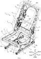
FIG. 1 is a diagram showing a vehicle seat device according to a first embodiment; -
FIG. 2 is a block diagram showing the vehicle seat device according to the first embodiment; -
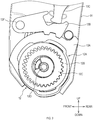
FIG. 3 is a diagram showing a reclining mechanism according to the first embodiment; -
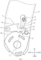
FIG. 4 is a diagram showing a folding down mechanism according to the first embodiment; -
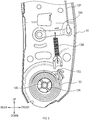
FIG. 5 is a diagram showing the folding down mechanism according to the first embodiment; -
FIG. 6 is a diagram showing the folding down mechanism according to the first embodiment; -
FIG. 7 is a diagram explaining operations of the vehicle seat device according to the first embodiment; and -
FIG. 8 is a flow chart showing operations of the vehicle seat device according to the first embodiment. - Embodiments explained hereinafter show examples of embodiments of the present disclosure. Matters to specify the invention recited in the claims are not limited to specific configurations or structures that are shown in the embodiments explained hereinafter.
- The present embodiments are examples of a vehicle seat device in the present disclosure used for a seat installed in a vehicle. Arrows indicating directions in the drawings are made for easy understanding of relationship between the drawings.
- Accordingly, the vehicle seat device should not be limited by the directions shown in the drawings. The directions in the drawings are defined in relation to the vehicle seat device according to the present embodiments that is assembled to a vehicle.
- In respect of a member or portion explained hereinafter, there is at least one in number of such a member or portion unless the number is otherwise specified as "only one of". In other words, there may be two or more of such a member or portion when the number is not specified as "only one of".
- As shown in
FIG. 1 , avehicle seat device 1 comprises at least aseat cushion 3 and aseatback 5. Seatmain body 2 is a collective name of portions including theseat cushion 3 and theseatback 5. - The
seat cushion 3 is a portion to support the buttocks of an occupant. Theseatback 5 is a portion to support the back of the occupant. Theseatback 5 is rotatable about its lower end. - A
cushion frame 7 forms a framework of theseat cushion 3. Thecushion frame 7 comprises at least twocushion side frames more coupling frames 73A to 73C (three coupling frames in the present embodiment). - The
coupling frames 73A to 73C extend along a seat-width axis and couple thecushion side frame 71 with thecushion side frame 72. Thecushion frame 7 is an approximately left-right symmetrical structure. Thecoupling frames 73A to 73C may be cylindrical rods. - A
back frame 9 forms a framework of theseatback 5. Theback frame 9 comprises at least twoback side frames 91, 92 (a leftback side frame 91 and a right back side frame 92) extending in approximately up-down directions when theseatback 5 is placed in a standing state (the state shown inFIG. 1 ) and two ormore coupling frames 93A to 93C (three coupling frames in the present embodiment). - The
coupling frames 93A to 93C extend along the seat-width axis and couple the leftback side frame 91 with the rightback side frame 92. Theback frame 9 is an approximately left-right symmetrical structure. - The
cushion frame 7, and therefore the seatmain body 2, is supported by two slidingdevices 10 so as to be slidable. The two slidingdevices 10 are identical structures, each comprising at least afixed rail 10A and amovable rail 10B, and optionally sharing a railelectric motor 10C. - Each fixed
rail 10A is a rail member securely fixed directly or indirectly to the vehicle. The seatmain body 2 is securely fixed to eachmovable rail 10B. Eachmovable rail 10B is slidable with respect to its corresponding fixedrail 10A - The rail
electric motor 10C exerts a driving force to slide eachmovable rail 10B. As shown inFIG. 2 , an operation of the railelectric motor 10C is controlled by amanipulation switch 10D and acontroller 14. Themanipulation switch 10D is situated, for example, on a side surface of theseat cushion 3. - The
controller 14 is situated in the seatmain body 2 or in the vehicle (in the seatmain body 2 in the present embodiment). In the present embodiment, a command signal from themanipulation switch 10D is inputted in thecontroller 14. In response to receiving the command signal, thecontroller 14 controls the operation of the railelectric motor 10C. - As shown in
FIG. 2 , atilt device 11 comprises at least areclining mechanism 12, a folding downmechanism 13, and thecontroller 14. Thecontroller 14 can control operations of thereclining mechanism 12 and folding downmechanism 13 and the like. - The
controller 14 comprises a microcomputer (not shown) comprising a CPU, an ROM, an RAM, and the like. A program to execute the control operation is pre-stored in a non-volatile storage device such as an ROM. -
FIG. 1 illustrates that theleft reclining mechanism 12 and theright reclining mechanism 12 are situated respectively on the left side and the right side of theseatback 5 across the seat-width axis. The tworeclining mechanisms 12 are identical structures except that they are left-right symmetric. Hereinafter, theleft reclining mechanism 12 on the left side will be explained. - The
left reclining mechanism 12 is installed in a lower end of an outer side of a leftback side frame 91. The outer side of the left backside frame 91 is a side face of the left backside frame 91 facing opposite the right backside frame 92 along the seat-width axis. - The
left reclining mechanism 12 according to the present embodiment is functioned by an electrically operated angleposition adjusting mechanism 12A. As shown inFIG. 3 , the angleposition adjusting mechanism 12A includes a taumel deceleration mechanism comprising at least an internallytoothed gear 12B and an externallytoothed gear 12C. - The internally
toothed gear 12B is an annular gear with all of its tooth tops protruding towards its center. The internallytoothed gear 12B is securely fixed, directly or indirectly, to thecushion side frame 71. In other words, the internallytoothed gear 12B can rotate in an integral state with thecushion side frame 71. - The externally
toothed gear 12C has all of its tooth tops protruding radially outwardly. The externallytoothed gear 12C meshes with the internallytoothed gear 12B and rotates as it circles inside the internallytoothed gear 12B. In other words, the externallytoothed gear 12C is a planetary gear rotating about its own center while revolving about the center of the internallytoothed gear 12B. - The externally
toothed gear 12C rotates in response to a supply of a rotational force from a recliningelectric motor 12E (seeFIG. 1 ) via adrive shaft 12D. As shown inFIG. 1 , thedrive shaft 12D extends along the seat-width axis and distributes the driving force to thereclining mechanisms 12 at a rotation center of theseatback 5. - If the number of teeth of the externally
toothed gear 12C is Z1 and the number of teeth of the internallytoothed gear 12B is Z2 (>Z1), then the externallytoothed gear 12C revolves (Z2-Z1) /Z2 × n degrees when the externallytoothed gear 12C rotates n degrees. - The center of rotation of the externally
toothed gear 12C accordingly moves in a direction of revolution with respect to its original position by every rotation of the externallytoothed gear 12C. More specifically, by every rotation of the externallytoothed gear 12C, the center of rotation of the externallytoothed gear 12C moves in the direction of revolution by 360-[ (Z2-Z1) /Z2 × 360]. - The externally
toothed gear 12C is securely and integrally fixed to a tiltingmember 13A (seeFIG. 4 ) by a fixing structure such as a weld. Thus, as the recliningelectric motor 12E (thedrive shaft 12D) rotates, the externallytoothed gear 12C moves in the direction of revolution and the tiltingmember 13A accordingly rotates in the direction of revolution. - That is, the force that moves the externally
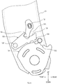
toothed gear 12C in the direction of revolution also serves as a force to rotate theseatback 5. In other words, theleft reclining mechanism 12 decelerates the rotation of the recliningelectric motor 12E and performs a function of transmitting the decelerated rotation to the tiltingmember 13A, and the externallytoothed gear 12C performs as an output gear of theleft reclining mechanism 12 which is included in the deceleration mechanism. - As shown in
FIG. 4 , the folding downmechanism 13 comprises at least the tiltingmember 13A, anengagement member 13B, an lockingmember 13C, aspring 13D (seeFIG. 5 ), and anelectric actuator 13E (seeFIG. 1 ). - As shown in
FIG. 4 , the tiltingmember 13A is arranged on the approximately same axis as a rotation center axis of theseatback 5. The tiltingmember 13A is a member configured to transmit a force to rotate (recline) theback frame 9 to the left backside frame 91. - In other words, the tilting
member 13A is configured to transmit the rotational force of the recliningelectric motor 12E, which is the output force of thereclining mechanism 12, to the seatback 5 (the left back side frame 91). The tiltingmember 13A is also called a ratchet plate or a rotation cam. - The tilting
member 13A is coupled to the left backside frame 91 so as to be rotatable with respect to the left backside frame 91. In other words, the tiltingmember 13A and the left back side frame 91 (the back frame 9) are independently rotatable with respect to the cushion side frame 71 (and with respect to each other). - The
engagement member 13B is coupled to the back frame 9 (the left backside frame 91 in the present embodiment) in a displaceable manner. Theengagement member 13B is also displaceable between an engaged position (seeFIG. 3 andFIG. 4 ) where theengagement member 13B is engaged with the tiltingmember 13A and a disengaged position (seeFIG. 6 ) where the engagement is released. Theengagement member 13B is also called a pawl. - As shown in
FIG. 4 , theengagement member 13B extends in the front-rear directions of the seat along a plate surface of the left backside frame 91 above the tiltingmember 13A. A seat front side portion of theengagement member 13B is rotatably coupled to the left backside frame 91 by acoupling pin 13F. - An
engagement portion 13H is situated in a seat rear side portion of theengagement member 13B. Theengagement portion 13H is configured to engage with anengagement target portion 13G situated in the tiltingmember 13A. Theengagement target portion 13G and theengagement portion 13H both include a concavo-convex shape and are fitted to mesh with each other for engagement. - During the engagement of the
engagement target portion 13G and theengagement portion 13H, the rotational force of the recliningelectric motor 12E transmitted to the tiltingmember 13A, which is the output force of thereclining mechanism 12, is transmittable to the left backside frame 91. - Accordingly, if the externally
toothed gear 12C revolves when theengagement member 13B is placed in the engaged position, the tiltingmember 13A and theback frame 9 rotate as one integrated member with respect to thecushion side frame 71. - When the
engagement target portion 13G and theengagement portion 13H are not engaged, the output force of thereclining mechanism 12 is not transmittable to the left backside frame 91; accordingly, the left backside frame 91 is rotatable with respect to the tiltingmember 13A. - Thus, when the
engagement member 13B is placed in the disengaged position, that is when theengagement member 13B is displaced upwards with respect to the tiltingmember 13A, a force of thespring 13D is transmittable to theseatback 5; accordingly, the left backside frame 91 can be tilted (folded down) towards the seat front side by the force of thespring 13D. - The locking
member 13C is displaceable between a locking position for retaining theengagement member 13B in the engaged position and a position displaced from the locking position (hereinafter referred to as unlocking position). The lockingmember 13C according to the present embodiment is situated above theengagement portion 13H and extends in approximately up-down directions along the plate surface of the left backside frame 91. - An upper portion of the locking
member 13C is rotatably coupled to the left backside frame 91 via acoupling pin 13J. Acam 13L configured to slide contact a sliding-contact portion 13K of theengagement member 13B is situated in a lower end of the lockingmember 13C. - When the locking
member 13C is placed in the locking position, a longitudinal axis of the lockingmember 13C is substantially parallel to an imaginary line Lo. The imaginary line Lo passes the pivot center of the lockingmember 13C and the pivot center of the tiltingmember 13A. -
FIG. 5 shows that arecovery spring 13M and anarm 13N are situated on the opposite side of the lockingmember 13C across the left backside frame 91, in other words, on a portion of the left backside frame 91 facing the right backside frame 92. - The
recovery spring 13M exerts a resilient force to retain the lockingmember 13C in the locking position via thearm 13N. One end of amanipulation cable 13P is coupled to a leading end of thearm 13N. - Returning to
FIG. 1 , the other end of themanipulation cable 13P is coupled to theactuator 13E. Thus, when themanipulation cable 13P is pulled by theactuator 13E, the lockingmember 13C is unlocked (displaced towards the unlocked position). - A spring (not shown) configured for retaining the
engagement member 13B in the disengaged position is situated in the left backside frame 91. Thus, as the lockingmember 13C is displaced to the unlocking position, theengagement member 13B is accordingly displaced towards the disengaged position by the resilient force of the spring. Then, when the lockingmember 13C returns from the unlocking position to the locking position, the lockingmember 13C displaces (returns) theengagement member 13B from the disengaged position to the engaged position. - Returning to
FIG. 5 , thespring 13D is situated in a portion of the left backside frame 91 facing the right backside frame 92. Thespring 13D exerts the resilient force to rotationally displace theback frame 9 towards the seat front side. - The
spring 13D according to the present embodiment is a spiral spring. An outerperipheral end 13Q of thespring 13D is securely fixed to the left backside frame 91 by locking. Acentral end 13R of thespring 13D is securely fixed to the externallytoothed gear 12C by locking. Thespring 13D is therefore enabled to apply, on theback frame 9, the resilient force enough to tilt the left backside frame 91 towards the seat front side. - The tilting
member 13A and the left backside frame 91 are integrated (engaged together) when theengagement member 13B is placed in the engaged position. In other words, the left backside frame 91 is immovable with respect to the tiltingmember 13A when theengagement member 13B is placed in the engaged position. - The tilting
member 13A is rotatable with respect to the left backside frame 91 when theengagement member 13B is placed in the disengaged position. In other words, the left backside frame 91 is rotatable with respect to the tiltingmember 13A by the resilient force of thespring 13D when theengagement member 13B is placed in the disengaged position (releasing the tiltingmember 13A from the left back side frame 91). - The
tilt device 11 can perform a tilt function for tilting theseatback 5 towards the seat front side by using the recliningelectric motor 12E and thespring 13D. In other words, as shown inFIG. 2 , thecontroller 14 can control operations of the recliningelectric motor 12E of thereclining mechanism 12 and theactuator 13E of the folding downmechanism 13. - When the tilt function is performed, the
tilt device 11, and therefore thecontroller 14, rotationally displaces theseatback 5 towards the seat front side to a preset position (hereinafter referred to as foremost position Pf) by operating the recliningelectric motor 12E, and then rotationally displaces theseatback 5 to the tilt state by using the force of thespring 13D. - The foremost position Pf according to the present embodiment (the position of the seat drawn in solid line in
FIG. 7 ) is the foremost location of theseatback 5 on the seat front side within a possible range of the rotational displacement of theseatback 5 by the recliningelectric motor 12E. In other words, thereclining mechanism 12 cannot cause a forward tilting rotation of theseatback 5 towards the seat front side beyond the foremost position Pf. - In the present embodiment, the seatback 5 (specifically the left and right back side frames 91 and 92) comes in contact with a limiter (not shown), such as a stopper, when the
seatback 5 reaches the foremost position Pf. Thus, the forward tilting rotation of theseatback 5 is mechanically stopped in the present embodiment. - When using the force of the
spring 13D during the operation of the tilt function, in other words, when tilting theseatback 5 to a position beyond the foremost position Pf (the position of the seat drawn in dashed-dotted lines inFIG. 7 ), thecontroller 14 stops the recliningelectric motor 12E and activates theactuator 13E to place theengagement member 13B in the disengaged position. This enables theseatback 5 to be tilted to a position beyond the foremost position Pf by the force of thespring 13D. - The
controller 14 enables the tilt function in a case of tilting theseatback 5 towards the seat front side from a position where theseatback 5 is tilted to a seat rear side beyond a preset position (hereinafter referred to as rear-tilt position Pr) (the position of the seat drawn in dashed double-dotted lines inFIG. 7 ). Hereinafter, this operation is called a walk-in operation. - When the walk-in operation is initiated and then the tilt function is ended, the
controller 14 activates the left and right slidingdevices 10, in other words, activates the railelectric motor 10C, and slides the seatmain body 2 towards the seat front side to a preset position. - In response to a conduction current value to the reclining
electric motor 12E exceeding a preset threshold value after the initiation of the tilt function, thecontroller 14 according to the present embodiment determines that theseatback 5 has reached the foremost position Pf and accordingly interrupts electric conduction to the recliningelectric motor 12E and activates theactuator 13E. - For this operation, the
controller 14 is provided with an input of signals of acurrent meter 14A configured to detect the conduction current value to the recliningelectric motor 12E. Thecontroller 14 is additionally provided with an input of signals of a forward-tilting-angle detection sensor 14B and signals of a rearward-tilting-angle detection sensor 14C. - The forward-tilting-
angle detection sensor 14B detects a forward-tilting angle of theseatback 5 to determine whether the tilt function is ended. The rearward-tilting-angle detection sensor 14C detects a rearward-tilting angle of theseatback 5 to detect whether theseatback 5 is tilted rearward beyond the rear-tilt position Pr. - The forward-tilting-
angle detection sensor 14B according to the present embodiment includes a limit switch or a proximity switch that is configured to deliver an ON signal in response to the forward-tilting angle of theseatback 5 bringing theseatback 5 in the tilt state. The rearward-tilting-angle detection sensor 14C includes a limit switch or a proximity switch that is configured to deliver an ON signal in response to the rearward-tilting angle of theseatback 5 bringing theseatback 5 beyond the rear-tilt position Pr. -
FIG. 8 is one example of a flowchart showing operations of thecontroller 14. Hereinafter, reference numerals in parentheses refer to reference numerals inFIG. 8 . - In response to a manipulation on a walk-
in switch 14D (seeFIG. 2 ), the walk-in operation begins. The walk-in switch 14D is situated at an upper end portion (shoulder) of theseatback 5 or on the side surface of theseat cushion 3. - The
controller 14 first determines whether theseatback 5 is tilted rearward beyond the rear-tilt position Pr (S1). If it is determined that theseatback 5 is not tilted rearward beyond the rear-tilt position Pr (S1:NO), then thecontroller 14 activates theactuator 13E to place theengagement member 13B in the disengaged position (S5). This causes theseatback 5 to be tilted forward beyond the foremost position Pf by the force of thespring 13D. - If it is determined that the
seatback 5 is tilted rearward beyond the rear-tilt position Pr (S1:YES), then thecontroller 14 activates the recliningelectric motor 12E (S2). This starts the rotational displacement of theseatback 5 towards the seat front side. Thecontroller 14 then determines whether theseatback 5 has reached the foremost position Pf (S3). - If it is determined that the
seatback 5 has not reached the foremost position Pf (S3:NO), then thecontroller 14 executes S3 again. If it is determined that theseatback 5 reaches the foremost position Pf (S3:YES), then thecontroller 14 interrupts the electric conduction to the recliningelectric motor 12E (S4) and activates theactuator 13E (S5). - The
controller 14 then determines whether the tilt function has ended (S6). If it is determined that the tilt function has not ended (S6:NO), then thecontroller 14 determines again whether the tilt function has ended (S6). - If it is determined that the tilt function has ended (S6:YES), then the
controller 14 activates the slidingdevice 10, and therefore the railelectric motor 10C (S7). Thecontroller 14 according to the present embodiment interrupts the electric conduction to the railelectric motor 10C in response to the conduction current to the railelectric motor 10C exceeding a rail current threshold value. - The
vehicle seat device 1 according to the present embodiment can enable the "folding down" through a hybrid method including the use of the recliningelectric motor 12E and thespring 13D. Accordingly, the spring force of thespring 13D in thevehicle seat device 1 can be less than the spring force in the invention disclosed inPatent Document 1. - When the tilt function is active, the
controller 14 rotationally displaces theseatback 5 towards the seat front side to the foremost position Pf by driving the recliningelectric motor 12E and then rotationally displaces theseatback 5 to the tilt state by using the spring force of thespring 13D. This can reduce the necessary spring force. - The
controller 14 stops the recliningelectric motor 12E when using the spring force of thespring 13D while the tilt function is active. This enables theseatback 5 to return to a previous position before the tilt when theseatback 5 returns to the standing state from the tilt state. - If the reclining
electric motor 12E is activated when theengagement member 13B is placed in the disengaged position, in other words, when the force of thespring 13D is acting on theseatback 5, then theseatback 5 returns to a position further forward than the previous position before the tilt when theseatback 5 returns to the standing state from the tilt state. - The
controller 14 enables the activation of the tilt function when tilting theseatback 5 towards the seat front side from a state where theseatback 5 is tilted rearward towards the seat rear side beyond the rear-tilt position Pr. This can positively reduce the spring force. - In the aforementioned embodiment, the
electric motor 12 E is stopped when using the force of thespring 13D during the operation of the tilt function. The present disclosure however should not be limited to the aforementioned embodiment. Alternatively, for example, theseatback 5 may be rotationally displaced to the tilt state by using the force of thespring 13D without stopping the recliningelectric motor 12E. - In the aforementioned embodiment, the activation of the tilt function is enabled when tilting the
seatback 5 towards the seat front side from a state where theseatback 5 is tilted rearward towards the seat rear side beyond the rear-tilt position Pr. - The present disclosure however should not be limited to the aforementioned embodiment. Alternatively, for example, the activation of the tilt function may be enabled when the
seatback 5 is still placed forward of the rear-tilt position Pr. - The foremost position Pf according to the aforementioned embodiment is the foremost location of the
seatback 5 on the seat front side within a possible range of the rotational displacement of theseatback 5 by the recliningelectric motor 12E. The present disclosure however should not be limited to the aforementioned embodiment. - The
controller 14 in the aforementioned embodiment determines that theseatback 5 has reached the foremost position Pf in response to the conduction current value to the recliningelectric motor 12E exceeding the preset threshold value after the initiation of the tilt function. The present disclosure however should not be limited to the aforementioned embodiment. Alternatively, for example, thecontroller 14 may be configured to determine whether theseatback 5 has reached the foremost position Pf by detecting the angle of rotation of theseatback 5 by using a device such as an encoder and a potentiometer. - The forward-tilting-
angle detection sensor 14B and the rearward-tilting-angle detection sensor 14C according to the aforementioned embodiment include the limit switch or the proximity switch. The present disclosure however should not be limited to the aforementioned embodiment. Alternatively, for example, the angle of rotation of theseatback 5 may be detected by using a device such as an encoder and a potentiometer.
Claims (8)
- A vehicle seat device (1) configured to be mounted to a vehicle comprising:a seat main body (2) having a seat cushion (3) and a seatback (5) rotatable about a lower end of the seatback (5); anda tilt device (11) having an electric motor (12E) and a spring (13D), the electric motor (12E) being configured to exert a rotational force to rotationally displace the seatback (5), and the spring (13D) being configured to exert a resilient force to rotationally displace the seatback (5) towards a seat front side;wherein the tilt device (11) further comprises:a tilting member (13A) arranged on an approximately same axis as a rotation center axis of the seatback (5), wherein the tilting member (13A) is configured to transmit the rotational force of the electric motor (12E) to the seatback (5) and is rotatable relative to the seatback (5);an engagement member (13B) coupled to the seatback (5) and displaceable between an engaged position for an engagement with the tilting member (13A) and a disengaged position where the engagement is released, wherein the engagement member (13B) is configured to enable transmission of the rotational force to the seatback (5) when placed in the engaged position; anda locking member (13C) configured to be displaceable between a locking position for retaining the engagement member (13B) in the engaged position and an unlocking position displaced from the locking position, characterized in thatthe tilt device (11) further comprises:an electric actuator (13E) configured to displace the locking member (13C); anda controller (14) configured to control an operation of the electric motor (12E) and the electric actuator (13E),wherein the tilt device (11) is configured to exert a tilt function to tilt the seatback (5) towards the seat front side by using the electric motor (12E) and the spring (13D), andwherein when the tilt function is active, the tilt device (11) rotationally displaces the seatback (5) towards the seat front side to a given first position (Pf) by driving the electric motor (12E) and then rotationally displaces the seatback (5) to a tilt state by using a force of the spring (13D).
- The vehicle seat device according to claim 1, wherein the tilt device (11) stops the electric motor (12E) when using a force of the spring (13D) while the tilt function is active.
- The vehicle seat device (1) according to claim 1 or 2, wherein the tilt function is configured to be active when tilting the seatback (5) towards the seat front side from a state where the seatback (5) is tilted rearward beyond a given second position (Pr) .
- The vehicle seat device (1) according to any one of claims 1 to 3,wherein the locking member (13C) is configured to be rotationally displaceable between the locking position and the unlocking position, andwherein the electric actuator (13E) is configured to rotationally displace the locking member (13C) via a manipulation cable (13P).
- The vehicle seat device (1) according to any one of claims 1 to 4, wherein a force of the spring (13D) is transmittable to the seatback (5) in response to an upward displacement of the engagement member (13B) relative to the tilting member (13A).
- The vehicle seat device (1) according to any one of claims 1 to 5 further comprising:a sliding device (10) configured to slide a seat main body (2),wherein the sliding device (10) is configured to slide the seat main body (2) towards the seat front side in response to an end of the tilt function.
- The vehicle seat device (1) according to any one of claims 1 to 6, wherein the given first position is a foremost location of the seatback (5) on the seat front side within a possible range of the rotational displacement of the seatback (5) by the electric motor (12E).
- The vehicle seat device (1) according to any one of claims 1 to 7,wherein the tilt device (11) comprisesa first reclining mechanism (12L) on a first end and a second reclining mechanism (12R) on a second end across a seat-width axis, wherein the first and the second reclining mechanisms (12L, 12R) are located at a rotation center of the seatback (5); anda drive shaft (12D) arranged in the rotation center of the seatback (5), wherein the drive shaft (12D) extends along the seat-width axis and is configured to transmit a driving force to the first and the second reclining mechanisms (12L, 12R), andwherein the electric motor (12E) is configured to provide the rotational force to the drive shaft (12D).
Applications Claiming Priority (1)
| Application Number | Priority Date | Filing Date | Title |
|---|---|---|---|
| JP2019001123A JP7116687B2 (en) | 2019-01-08 | 2019-01-08 | Vehicle seat device |
Publications (2)
| Publication Number | Publication Date |
|---|---|
| EP3680126A1 EP3680126A1 (en) | 2020-07-15 |
| EP3680126B1 true EP3680126B1 (en) | 2021-09-29 |
Family
ID=69143430
Family Applications (1)
| Application Number | Title | Priority Date | Filing Date |
|---|---|---|---|
| EP20150444.6A Active EP3680126B1 (en) | 2019-01-08 | 2020-01-07 | Vehicle seat device |
Country Status (4)
| Country | Link |
|---|---|
| US (1) | US11065985B2 (en) |
| EP (1) | EP3680126B1 (en) |
| JP (1) | JP7116687B2 (en) |
| CN (1) | CN111497696B (en) |
Families Citing this family (8)
| Publication number | Priority date | Publication date | Assignee | Title |
|---|---|---|---|---|
| KR102706253B1 (en) * | 2019-06-14 | 2024-09-12 | 현대자동차주식회사 | Walkin apparatus of seat for vehicle |
| KR102923449B1 (en) * | 2020-10-12 | 2026-02-06 | 현대자동차주식회사 | Seat Having Dual Gear Type Recliner Device for Vehicle |
| WO2022174147A1 (en) * | 2021-02-12 | 2022-08-18 | Magna Seating Inc. | Seat with power pitch easy entry having lower disc actuator |
| KR102442152B1 (en) * | 2021-06-01 | 2022-09-08 | 주식회사 다스 | Seat walk-in device |
| KR102627616B1 (en) * | 2022-01-06 | 2024-01-23 | 현대트랜시스 주식회사 | Power Recliner Structure |
| KR102730028B1 (en) | 2022-08-12 | 2024-11-15 | 현대트랜시스 주식회사 | Seatback folding device for emergency escape |
| KR20240076912A (en) * | 2022-11-24 | 2024-05-31 | 현대자동차주식회사 | Device for locking walk-in seat of vehicle |
| KR102841842B1 (en) * | 2024-12-12 | 2025-08-04 | 주식회사 엠리무진 | Electric seat assembly for vehicle |
Family Cites Families (25)
| Publication number | Priority date | Publication date | Assignee | Title |
|---|---|---|---|---|
| JPH06328973A (en) * | 1993-05-21 | 1994-11-29 | Mitsubishi Electric Corp | Seat having driving device |
| DE19652665C1 (en) * | 1996-12-18 | 1998-05-07 | Faure Bertrand Sitztech Gmbh | Ratchet locking device for adjustable seat back in vehicle |
| DE19960878A1 (en) * | 1999-12-17 | 2001-07-05 | Keiper Gmbh & Co | Locking fitting for a vehicle seat, in particular for a motor vehicle seat |
| JP4608751B2 (en) | 2000-08-30 | 2011-01-12 | アイシン精機株式会社 | Vehicle seat reclining device |
| EP1491388A3 (en) | 2003-06-24 | 2005-10-19 | Aisin Seiki Kabushiki Kaisha | Electrically foldable seat |
| JP4922627B2 (en) | 2006-02-28 | 2012-04-25 | 富士機工株式会社 | Vehicle seat reclining device |
| EP2144783A1 (en) * | 2007-03-09 | 2010-01-20 | Johnson Controls GmbH | Vehicle seat with a tumbling recliner |
| US7819479B2 (en) * | 2007-10-10 | 2010-10-26 | Lear Corporation | Vehicle seat assembly having walk-in and fold-flat features |
| DE102008036630A1 (en) * | 2007-10-26 | 2009-04-30 | C. Rob. Hammerstein Gmbh & Co. Kg | Foldable motor vehicle seat with a hinge fitting |
| DE102008036613A1 (en) * | 2007-10-26 | 2009-04-30 | C. Rob. Hammerstein Gmbh & Co. Kg | Foldable motor vehicle seat |
| JP2010233840A (en) | 2009-03-31 | 2010-10-21 | Aisin Seiki Co Ltd | Seat reclining device |
| JP5278268B2 (en) * | 2009-09-25 | 2013-09-04 | 株式会社今仙電機製作所 | Sheet device |
| DE102009043140B3 (en) | 2009-09-26 | 2011-03-24 | Faureica Autositze Gmbh | Motor vehicle seat, has cam ring supported at push pull cable tightening disk, where relative position between disk and ring is fixed by inserting blocking element into recesses after reaching desired position between ring and lever |
| DE102010019697B4 (en) * | 2010-05-05 | 2013-10-17 | Keiper Gmbh & Co. Kg | Fitting for a vehicle seat and vehicle seat |
| JP2012148753A (en) * | 2010-12-28 | 2012-08-09 | Imasen Electric Ind Co Ltd | Vehicular power seat device |
| JP5684000B2 (en) * | 2011-02-28 | 2015-03-11 | ダイハツ工業株式会社 | Vehicle seat device |
| JP5691793B2 (en) | 2011-04-22 | 2015-04-01 | アイシン精機株式会社 | Seat reclining device |
| FR2975052B1 (en) * | 2011-05-11 | 2014-02-07 | Faurecia Sieges Automobile | JOINT ASSEMBLY FOR VEHICLE SEAT AND VEHICLE SEAT COMPRISING THE JOINT ASSEMBLY |
| JP6232983B2 (en) | 2013-12-03 | 2017-11-22 | アイシン精機株式会社 | Deceleration device and seat drive device |
| JP2016216004A (en) * | 2015-05-26 | 2016-12-22 | トヨタ紡織株式会社 | Seat for vehicle |
| JP6659433B2 (en) | 2016-04-14 | 2020-03-04 | 日本発條株式会社 | Reclining device for vehicle seat and vehicle seat having the reclining device |
| JP6607142B2 (en) * | 2016-05-18 | 2019-11-20 | トヨタ紡織株式会社 | Seat drive device |
| JP6690408B2 (en) * | 2016-05-27 | 2020-04-28 | トヨタ紡織株式会社 | Seat adjuster |
| US9868369B1 (en) * | 2016-07-15 | 2018-01-16 | Ford Global Technologies, Llc | Tip and slide system for a vehicle seat |
| JP6750471B2 (en) * | 2016-11-21 | 2020-09-02 | トヨタ紡織株式会社 | Vehicle seat |
-
2019
- 2019-01-08 JP JP2019001123A patent/JP7116687B2/en active Active
- 2019-12-31 CN CN201911411084.7A patent/CN111497696B/en active Active
-
2020
- 2020-01-02 US US16/732,902 patent/US11065985B2/en active Active
- 2020-01-07 EP EP20150444.6A patent/EP3680126B1/en active Active
Also Published As
| Publication number | Publication date |
|---|---|
| US11065985B2 (en) | 2021-07-20 |
| JP7116687B2 (en) | 2022-08-10 |
| US20200215935A1 (en) | 2020-07-09 |
| CN111497696B (en) | 2023-06-30 |
| CN111497696A (en) | 2020-08-07 |
| EP3680126A1 (en) | 2020-07-15 |
| JP2020111074A (en) | 2020-07-27 |
Similar Documents
| Publication | Publication Date | Title |
|---|---|---|
| EP3680126B1 (en) | Vehicle seat device | |
| JP4620757B2 (en) | Sheet device | |
| EP1420978B1 (en) | Tip easy entry and fold flat recliner assembly | |
| EP2236348A2 (en) | Seat reclining apparatus | |
| EP2293960B1 (en) | Disc recliner with integral travel stops | |
| EP2565070A2 (en) | Power fold with lock for vehicle seat | |
| EP1764260A2 (en) | Device for vehicle seat | |
| US11130426B2 (en) | Seatback rotating device | |
| JP4185935B2 (en) | Sheet | |
| CN102317109A (en) | Occupant protection device | |
| US8511750B2 (en) | Vehicle seat device | |
| CN107444203B (en) | Seat adjusting device and vehicle seat | |
| US10518669B2 (en) | Vehicle seat | |
| EP2464540A1 (en) | Modular recline mechanism and sidemember for rotary recliner | |
| WO2012124381A1 (en) | Vehicle seat | |
| US11180057B2 (en) | Seatback rotating device | |
| JP4430602B2 (en) | Vehicle seat device | |
| KR102208804B1 (en) | Work-In and Folding Apparatus for Motor Vehicle Seat | |
| JP4622772B2 (en) | Vehicle seat device | |
| CN113795405A (en) | An adjustment accessory for a vehicle seat and a vehicle seat | |
| JP4622771B2 (en) | Vehicle seat device | |
| JP4460518B2 (en) | Vehicle seat device | |
| JP5187378B2 (en) | Vehicle seat device | |
| JP2012176737A (en) | Vehicular seat control device | |
| JP7263808B2 (en) | Posture control system and vehicle seat |
Legal Events
| Date | Code | Title | Description |
|---|---|---|---|
| PUAI | Public reference made under article 153(3) epc to a published international application that has entered the european phase |
Free format text: ORIGINAL CODE: 0009012 |
|
| STAA | Information on the status of an ep patent application or granted ep patent |
Free format text: STATUS: THE APPLICATION HAS BEEN PUBLISHED |
|
| AK | Designated contracting states |
Kind code of ref document: A1 Designated state(s): AL AT BE BG CH CY CZ DE DK EE ES FI FR GB GR HR HU IE IS IT LI LT LU LV MC MK MT NL NO PL PT RO RS SE SI SK SM TR |
|
| AX | Request for extension of the european patent |
Extension state: BA ME |
|
| STAA | Information on the status of an ep patent application or granted ep patent |
Free format text: STATUS: REQUEST FOR EXAMINATION WAS MADE |
|
| 17P | Request for examination filed |
Effective date: 20201119 |
|
| RBV | Designated contracting states (corrected) |
Designated state(s): AL AT BE BG CH CY CZ DE DK EE ES FI FR GB GR HR HU IE IS IT LI LT LU LV MC MK MT NL NO PL PT RO RS SE SI SK SM TR |
|
| GRAP | Despatch of communication of intention to grant a patent |
Free format text: ORIGINAL CODE: EPIDOSNIGR1 |
|
| STAA | Information on the status of an ep patent application or granted ep patent |
Free format text: STATUS: GRANT OF PATENT IS INTENDED |
|
| INTG | Intention to grant announced |
Effective date: 20210430 |
|
| GRAS | Grant fee paid |
Free format text: ORIGINAL CODE: EPIDOSNIGR3 |
|
| GRAA | (expected) grant |
Free format text: ORIGINAL CODE: 0009210 |
|
| STAA | Information on the status of an ep patent application or granted ep patent |
Free format text: STATUS: THE PATENT HAS BEEN GRANTED |
|
| AK | Designated contracting states |
Kind code of ref document: B1 Designated state(s): AL AT BE BG CH CY CZ DE DK EE ES FI FR GB GR HR HU IE IS IT LI LT LU LV MC MK MT NL NO PL PT RO RS SE SI SK SM TR |
|
| REG | Reference to a national code |
Ref country code: GB Ref legal event code: FG4D |
|
| REG | Reference to a national code |
Ref country code: CH Ref legal event code: EP Ref country code: AT Ref legal event code: REF Ref document number: 1433916 Country of ref document: AT Kind code of ref document: T Effective date: 20211015 |
|
| REG | Reference to a national code |
Ref country code: DE Ref legal event code: R096 Ref document number: 602020000600 Country of ref document: DE |
|
| REG | Reference to a national code |
Ref country code: IE Ref legal event code: FG4D |
|
| REG | Reference to a national code |
Ref country code: LT Ref legal event code: MG9D |
|
| PG25 | Lapsed in a contracting state [announced via postgrant information from national office to epo] |
Ref country code: LT Free format text: LAPSE BECAUSE OF FAILURE TO SUBMIT A TRANSLATION OF THE DESCRIPTION OR TO PAY THE FEE WITHIN THE PRESCRIBED TIME-LIMIT Effective date: 20210929 Ref country code: BG Free format text: LAPSE BECAUSE OF FAILURE TO SUBMIT A TRANSLATION OF THE DESCRIPTION OR TO PAY THE FEE WITHIN THE PRESCRIBED TIME-LIMIT Effective date: 20211229 Ref country code: NO Free format text: LAPSE BECAUSE OF FAILURE TO SUBMIT A TRANSLATION OF THE DESCRIPTION OR TO PAY THE FEE WITHIN THE PRESCRIBED TIME-LIMIT Effective date: 20211229 Ref country code: FI Free format text: LAPSE BECAUSE OF FAILURE TO SUBMIT A TRANSLATION OF THE DESCRIPTION OR TO PAY THE FEE WITHIN THE PRESCRIBED TIME-LIMIT Effective date: 20210929 Ref country code: HR Free format text: LAPSE BECAUSE OF FAILURE TO SUBMIT A TRANSLATION OF THE DESCRIPTION OR TO PAY THE FEE WITHIN THE PRESCRIBED TIME-LIMIT Effective date: 20210929 Ref country code: RS Free format text: LAPSE BECAUSE OF FAILURE TO SUBMIT A TRANSLATION OF THE DESCRIPTION OR TO PAY THE FEE WITHIN THE PRESCRIBED TIME-LIMIT Effective date: 20210929 Ref country code: SE Free format text: LAPSE BECAUSE OF FAILURE TO SUBMIT A TRANSLATION OF THE DESCRIPTION OR TO PAY THE FEE WITHIN THE PRESCRIBED TIME-LIMIT Effective date: 20210929 |
|
| REG | Reference to a national code |
Ref country code: NL Ref legal event code: MP Effective date: 20210929 |
|
| REG | Reference to a national code |
Ref country code: AT Ref legal event code: MK05 Ref document number: 1433916 Country of ref document: AT Kind code of ref document: T Effective date: 20210929 |
|
| PG25 | Lapsed in a contracting state [announced via postgrant information from national office to epo] |
Ref country code: LV Free format text: LAPSE BECAUSE OF FAILURE TO SUBMIT A TRANSLATION OF THE DESCRIPTION OR TO PAY THE FEE WITHIN THE PRESCRIBED TIME-LIMIT Effective date: 20210929 Ref country code: GR Free format text: LAPSE BECAUSE OF FAILURE TO SUBMIT A TRANSLATION OF THE DESCRIPTION OR TO PAY THE FEE WITHIN THE PRESCRIBED TIME-LIMIT Effective date: 20211230 |
|
| PG25 | Lapsed in a contracting state [announced via postgrant information from national office to epo] |
Ref country code: AT Free format text: LAPSE BECAUSE OF FAILURE TO SUBMIT A TRANSLATION OF THE DESCRIPTION OR TO PAY THE FEE WITHIN THE PRESCRIBED TIME-LIMIT Effective date: 20210929 |
|
| PG25 | Lapsed in a contracting state [announced via postgrant information from national office to epo] |
Ref country code: IS Free format text: LAPSE BECAUSE OF FAILURE TO SUBMIT A TRANSLATION OF THE DESCRIPTION OR TO PAY THE FEE WITHIN THE PRESCRIBED TIME-LIMIT Effective date: 20220129 Ref country code: SK Free format text: LAPSE BECAUSE OF FAILURE TO SUBMIT A TRANSLATION OF THE DESCRIPTION OR TO PAY THE FEE WITHIN THE PRESCRIBED TIME-LIMIT Effective date: 20210929 Ref country code: RO Free format text: LAPSE BECAUSE OF FAILURE TO SUBMIT A TRANSLATION OF THE DESCRIPTION OR TO PAY THE FEE WITHIN THE PRESCRIBED TIME-LIMIT Effective date: 20210929 Ref country code: PT Free format text: LAPSE BECAUSE OF FAILURE TO SUBMIT A TRANSLATION OF THE DESCRIPTION OR TO PAY THE FEE WITHIN THE PRESCRIBED TIME-LIMIT Effective date: 20220131 Ref country code: PL Free format text: LAPSE BECAUSE OF FAILURE TO SUBMIT A TRANSLATION OF THE DESCRIPTION OR TO PAY THE FEE WITHIN THE PRESCRIBED TIME-LIMIT Effective date: 20210929 Ref country code: NL Free format text: LAPSE BECAUSE OF FAILURE TO SUBMIT A TRANSLATION OF THE DESCRIPTION OR TO PAY THE FEE WITHIN THE PRESCRIBED TIME-LIMIT Effective date: 20210929 Ref country code: ES Free format text: LAPSE BECAUSE OF FAILURE TO SUBMIT A TRANSLATION OF THE DESCRIPTION OR TO PAY THE FEE WITHIN THE PRESCRIBED TIME-LIMIT Effective date: 20210929 Ref country code: EE Free format text: LAPSE BECAUSE OF FAILURE TO SUBMIT A TRANSLATION OF THE DESCRIPTION OR TO PAY THE FEE WITHIN THE PRESCRIBED TIME-LIMIT Effective date: 20210929 Ref country code: CZ Free format text: LAPSE BECAUSE OF FAILURE TO SUBMIT A TRANSLATION OF THE DESCRIPTION OR TO PAY THE FEE WITHIN THE PRESCRIBED TIME-LIMIT Effective date: 20210929 Ref country code: AL Free format text: LAPSE BECAUSE OF FAILURE TO SUBMIT A TRANSLATION OF THE DESCRIPTION OR TO PAY THE FEE WITHIN THE PRESCRIBED TIME-LIMIT Effective date: 20210929 |
|
| REG | Reference to a national code |
Ref country code: DE Ref legal event code: R097 Ref document number: 602020000600 Country of ref document: DE |
|
| PG25 | Lapsed in a contracting state [announced via postgrant information from national office to epo] |
Ref country code: DK Free format text: LAPSE BECAUSE OF FAILURE TO SUBMIT A TRANSLATION OF THE DESCRIPTION OR TO PAY THE FEE WITHIN THE PRESCRIBED TIME-LIMIT Effective date: 20210929 |
|
| PLBE | No opposition filed within time limit |
Free format text: ORIGINAL CODE: 0009261 |
|
| STAA | Information on the status of an ep patent application or granted ep patent |
Free format text: STATUS: NO OPPOSITION FILED WITHIN TIME LIMIT |
|
| PG25 | Lapsed in a contracting state [announced via postgrant information from national office to epo] |
Ref country code: MC Free format text: LAPSE BECAUSE OF FAILURE TO SUBMIT A TRANSLATION OF THE DESCRIPTION OR TO PAY THE FEE WITHIN THE PRESCRIBED TIME-LIMIT Effective date: 20210929 |
|
| 26N | No opposition filed |
Effective date: 20220630 |
|
| REG | Reference to a national code |
Ref country code: BE Ref legal event code: MM Effective date: 20220131 |
|
| PG25 | Lapsed in a contracting state [announced via postgrant information from national office to epo] |
Ref country code: LU Free format text: LAPSE BECAUSE OF NON-PAYMENT OF DUE FEES Effective date: 20220107 |
|
| PG25 | Lapsed in a contracting state [announced via postgrant information from national office to epo] |
Ref country code: SI Free format text: LAPSE BECAUSE OF FAILURE TO SUBMIT A TRANSLATION OF THE DESCRIPTION OR TO PAY THE FEE WITHIN THE PRESCRIBED TIME-LIMIT Effective date: 20210929 Ref country code: FR Free format text: LAPSE BECAUSE OF NON-PAYMENT OF DUE FEES Effective date: 20220131 Ref country code: BE Free format text: LAPSE BECAUSE OF NON-PAYMENT OF DUE FEES Effective date: 20220131 |
|
| PG25 | Lapsed in a contracting state [announced via postgrant information from national office to epo] |
Ref country code: IT Free format text: LAPSE BECAUSE OF FAILURE TO SUBMIT A TRANSLATION OF THE DESCRIPTION OR TO PAY THE FEE WITHIN THE PRESCRIBED TIME-LIMIT Effective date: 20210929 Ref country code: IE Free format text: LAPSE BECAUSE OF NON-PAYMENT OF DUE FEES Effective date: 20220107 |
|
| REG | Reference to a national code |
Ref country code: CH Ref legal event code: PL |
|
| PG25 | Lapsed in a contracting state [announced via postgrant information from national office to epo] |
Ref country code: LI Free format text: LAPSE BECAUSE OF NON-PAYMENT OF DUE FEES Effective date: 20230131 Ref country code: CH Free format text: LAPSE BECAUSE OF NON-PAYMENT OF DUE FEES Effective date: 20230131 |
|
| PG25 | Lapsed in a contracting state [announced via postgrant information from national office to epo] |
Ref country code: SM Free format text: LAPSE BECAUSE OF FAILURE TO SUBMIT A TRANSLATION OF THE DESCRIPTION OR TO PAY THE FEE WITHIN THE PRESCRIBED TIME-LIMIT Effective date: 20210929 Ref country code: MK Free format text: LAPSE BECAUSE OF FAILURE TO SUBMIT A TRANSLATION OF THE DESCRIPTION OR TO PAY THE FEE WITHIN THE PRESCRIBED TIME-LIMIT Effective date: 20210929 Ref country code: CY Free format text: LAPSE BECAUSE OF FAILURE TO SUBMIT A TRANSLATION OF THE DESCRIPTION OR TO PAY THE FEE WITHIN THE PRESCRIBED TIME-LIMIT Effective date: 20210929 |
|
| PG25 | Lapsed in a contracting state [announced via postgrant information from national office to epo] |
Ref country code: HU Free format text: LAPSE BECAUSE OF FAILURE TO SUBMIT A TRANSLATION OF THE DESCRIPTION OR TO PAY THE FEE WITHIN THE PRESCRIBED TIME-LIMIT; INVALID AB INITIO Effective date: 20200107 |
|
| GBPC | Gb: european patent ceased through non-payment of renewal fee |
Effective date: 20240107 |
|
| PG25 | Lapsed in a contracting state [announced via postgrant information from national office to epo] |
Ref country code: MT Free format text: LAPSE BECAUSE OF FAILURE TO SUBMIT A TRANSLATION OF THE DESCRIPTION OR TO PAY THE FEE WITHIN THE PRESCRIBED TIME-LIMIT Effective date: 20210929 |
|
| PG25 | Lapsed in a contracting state [announced via postgrant information from national office to epo] |
Ref country code: GB Free format text: LAPSE BECAUSE OF NON-PAYMENT OF DUE FEES Effective date: 20240107 |
|
| PG25 | Lapsed in a contracting state [announced via postgrant information from national office to epo] |
Ref country code: GB Free format text: LAPSE BECAUSE OF NON-PAYMENT OF DUE FEES Effective date: 20240107 |
|
| PG25 | Lapsed in a contracting state [announced via postgrant information from national office to epo] |
Ref country code: TR Free format text: LAPSE BECAUSE OF FAILURE TO SUBMIT A TRANSLATION OF THE DESCRIPTION OR TO PAY THE FEE WITHIN THE PRESCRIBED TIME-LIMIT Effective date: 20210929 |
|
| PGFP | Annual fee paid to national office [announced via postgrant information from national office to epo] |
Ref country code: DE Payment date: 20251203 Year of fee payment: 7 |