EP3679902A2 - Stentdesigns zur abdeckung einer katheterzugangsstelle - Google Patents
Stentdesigns zur abdeckung einer katheterzugangsstelle Download PDFInfo
- Publication number
- EP3679902A2 EP3679902A2 EP20150480.0A EP20150480A EP3679902A2 EP 3679902 A2 EP3679902 A2 EP 3679902A2 EP 20150480 A EP20150480 A EP 20150480A EP 3679902 A2 EP3679902 A2 EP 3679902A2
- Authority
- EP
- European Patent Office
- Prior art keywords
- stent
- deployable member
- hole
- wall
- body lumen
- Prior art date
- Legal status (The legal status is an assumption and is not a legal conclusion. Google has not performed a legal analysis and makes no representation as to the accuracy of the status listed.)
- Pending
Links
Images


Classifications
-
- A—HUMAN NECESSITIES
- A61—MEDICAL OR VETERINARY SCIENCE; HYGIENE
- A61F—FILTERS IMPLANTABLE INTO BLOOD VESSELS; PROSTHESES; DEVICES PROVIDING PATENCY TO, OR PREVENTING COLLAPSING OF, TUBULAR STRUCTURES OF THE BODY, e.g. STENTS; ORTHOPAEDIC, NURSING OR CONTRACEPTIVE DEVICES; FOMENTATION; TREATMENT OR PROTECTION OF EYES OR EARS; BANDAGES, DRESSINGS OR ABSORBENT PADS; FIRST-AID KITS
- A61F2/00—Filters implantable into blood vessels; Prostheses, i.e. artificial substitutes or replacements for parts of the body; Appliances for connecting them with the body; Devices providing patency to, or preventing collapsing of, tubular structures of the body, e.g. stents
- A61F2/02—Prostheses implantable into the body
- A61F2/04—Hollow or tubular parts of organs, e.g. bladders, tracheae, bronchi or bile ducts
-
- A—HUMAN NECESSITIES
- A61—MEDICAL OR VETERINARY SCIENCE; HYGIENE
- A61F—FILTERS IMPLANTABLE INTO BLOOD VESSELS; PROSTHESES; DEVICES PROVIDING PATENCY TO, OR PREVENTING COLLAPSING OF, TUBULAR STRUCTURES OF THE BODY, e.g. STENTS; ORTHOPAEDIC, NURSING OR CONTRACEPTIVE DEVICES; FOMENTATION; TREATMENT OR PROTECTION OF EYES OR EARS; BANDAGES, DRESSINGS OR ABSORBENT PADS; FIRST-AID KITS
- A61F2/00—Filters implantable into blood vessels; Prostheses, i.e. artificial substitutes or replacements for parts of the body; Appliances for connecting them with the body; Devices providing patency to, or preventing collapsing of, tubular structures of the body, e.g. stents
- A61F2/82—Devices providing patency to, or preventing collapsing of, tubular structures of the body, e.g. stents
-
- A—HUMAN NECESSITIES
- A61—MEDICAL OR VETERINARY SCIENCE; HYGIENE
- A61F—FILTERS IMPLANTABLE INTO BLOOD VESSELS; PROSTHESES; DEVICES PROVIDING PATENCY TO, OR PREVENTING COLLAPSING OF, TUBULAR STRUCTURES OF THE BODY, e.g. STENTS; ORTHOPAEDIC, NURSING OR CONTRACEPTIVE DEVICES; FOMENTATION; TREATMENT OR PROTECTION OF EYES OR EARS; BANDAGES, DRESSINGS OR ABSORBENT PADS; FIRST-AID KITS
- A61F2/00—Filters implantable into blood vessels; Prostheses, i.e. artificial substitutes or replacements for parts of the body; Appliances for connecting them with the body; Devices providing patency to, or preventing collapsing of, tubular structures of the body, e.g. stents
- A61F2/02—Prostheses implantable into the body
- A61F2/04—Hollow or tubular parts of organs, e.g. bladders, tracheae, bronchi or bile ducts
- A61F2/06—Blood vessels
- A61F2/07—Stent-grafts
-
- A—HUMAN NECESSITIES
- A61—MEDICAL OR VETERINARY SCIENCE; HYGIENE
- A61F—FILTERS IMPLANTABLE INTO BLOOD VESSELS; PROSTHESES; DEVICES PROVIDING PATENCY TO, OR PREVENTING COLLAPSING OF, TUBULAR STRUCTURES OF THE BODY, e.g. STENTS; ORTHOPAEDIC, NURSING OR CONTRACEPTIVE DEVICES; FOMENTATION; TREATMENT OR PROTECTION OF EYES OR EARS; BANDAGES, DRESSINGS OR ABSORBENT PADS; FIRST-AID KITS
- A61F2/00—Filters implantable into blood vessels; Prostheses, i.e. artificial substitutes or replacements for parts of the body; Appliances for connecting them with the body; Devices providing patency to, or preventing collapsing of, tubular structures of the body, e.g. stents
- A61F2/82—Devices providing patency to, or preventing collapsing of, tubular structures of the body, e.g. stents
- A61F2/844—Devices providing patency to, or preventing collapsing of, tubular structures of the body, e.g. stents folded prior to deployment
-
- A—HUMAN NECESSITIES
- A61—MEDICAL OR VETERINARY SCIENCE; HYGIENE
- A61F—FILTERS IMPLANTABLE INTO BLOOD VESSELS; PROSTHESES; DEVICES PROVIDING PATENCY TO, OR PREVENTING COLLAPSING OF, TUBULAR STRUCTURES OF THE BODY, e.g. STENTS; ORTHOPAEDIC, NURSING OR CONTRACEPTIVE DEVICES; FOMENTATION; TREATMENT OR PROTECTION OF EYES OR EARS; BANDAGES, DRESSINGS OR ABSORBENT PADS; FIRST-AID KITS
- A61F2/00—Filters implantable into blood vessels; Prostheses, i.e. artificial substitutes or replacements for parts of the body; Appliances for connecting them with the body; Devices providing patency to, or preventing collapsing of, tubular structures of the body, e.g. stents
- A61F2/95—Instruments specially adapted for placement or removal of stents or stent-grafts
- A61F2/962—Instruments specially adapted for placement or removal of stents or stent-grafts having an outer sleeve
- A61F2/966—Instruments specially adapted for placement or removal of stents or stent-grafts having an outer sleeve with relative longitudinal movement between outer sleeve and prosthesis, e.g. using a push rod
-
- A—HUMAN NECESSITIES
- A61—MEDICAL OR VETERINARY SCIENCE; HYGIENE
- A61F—FILTERS IMPLANTABLE INTO BLOOD VESSELS; PROSTHESES; DEVICES PROVIDING PATENCY TO, OR PREVENTING COLLAPSING OF, TUBULAR STRUCTURES OF THE BODY, e.g. STENTS; ORTHOPAEDIC, NURSING OR CONTRACEPTIVE DEVICES; FOMENTATION; TREATMENT OR PROTECTION OF EYES OR EARS; BANDAGES, DRESSINGS OR ABSORBENT PADS; FIRST-AID KITS
- A61F2/00—Filters implantable into blood vessels; Prostheses, i.e. artificial substitutes or replacements for parts of the body; Appliances for connecting them with the body; Devices providing patency to, or preventing collapsing of, tubular structures of the body, e.g. stents
- A61F2/95—Instruments specially adapted for placement or removal of stents or stent-grafts
- A61F2/962—Instruments specially adapted for placement or removal of stents or stent-grafts having an outer sleeve
- A61F2/97—Instruments specially adapted for placement or removal of stents or stent-grafts having an outer sleeve the outer sleeve being splittable
-
- A—HUMAN NECESSITIES
- A61—MEDICAL OR VETERINARY SCIENCE; HYGIENE
- A61B—DIAGNOSIS; SURGERY; IDENTIFICATION
- A61B17/00—Surgical instruments, devices or methods
- A61B17/0057—Implements for plugging an opening in the wall of a hollow or tubular organ, e.g. for sealing a vessel puncture or closing a cardiac septal defect
- A61B2017/00646—Type of implements
- A61B2017/00659—Type of implements located only on one side of the opening
-
- A—HUMAN NECESSITIES
- A61—MEDICAL OR VETERINARY SCIENCE; HYGIENE
- A61F—FILTERS IMPLANTABLE INTO BLOOD VESSELS; PROSTHESES; DEVICES PROVIDING PATENCY TO, OR PREVENTING COLLAPSING OF, TUBULAR STRUCTURES OF THE BODY, e.g. STENTS; ORTHOPAEDIC, NURSING OR CONTRACEPTIVE DEVICES; FOMENTATION; TREATMENT OR PROTECTION OF EYES OR EARS; BANDAGES, DRESSINGS OR ABSORBENT PADS; FIRST-AID KITS
- A61F2/00—Filters implantable into blood vessels; Prostheses, i.e. artificial substitutes or replacements for parts of the body; Appliances for connecting them with the body; Devices providing patency to, or preventing collapsing of, tubular structures of the body, e.g. stents
- A61F2/82—Devices providing patency to, or preventing collapsing of, tubular structures of the body, e.g. stents
- A61F2/86—Stents in a form characterised by the wire-like elements; Stents in the form characterised by a net-like or mesh-like structure
- A61F2/90—Stents in a form characterised by the wire-like elements; Stents in the form characterised by a net-like or mesh-like structure characterised by a net-like or mesh-like structure
- A61F2/91—Stents in a form characterised by the wire-like elements; Stents in the form characterised by a net-like or mesh-like structure characterised by a net-like or mesh-like structure made from perforated sheets or tubes, e.g. perforated by laser cuts or etched holes
-
- A—HUMAN NECESSITIES
- A61—MEDICAL OR VETERINARY SCIENCE; HYGIENE
- A61F—FILTERS IMPLANTABLE INTO BLOOD VESSELS; PROSTHESES; DEVICES PROVIDING PATENCY TO, OR PREVENTING COLLAPSING OF, TUBULAR STRUCTURES OF THE BODY, e.g. STENTS; ORTHOPAEDIC, NURSING OR CONTRACEPTIVE DEVICES; FOMENTATION; TREATMENT OR PROTECTION OF EYES OR EARS; BANDAGES, DRESSINGS OR ABSORBENT PADS; FIRST-AID KITS
- A61F2/00—Filters implantable into blood vessels; Prostheses, i.e. artificial substitutes or replacements for parts of the body; Appliances for connecting them with the body; Devices providing patency to, or preventing collapsing of, tubular structures of the body, e.g. stents
- A61F2/02—Prostheses implantable into the body
- A61F2/04—Hollow or tubular parts of organs, e.g. bladders, tracheae, bronchi or bile ducts
- A61F2002/045—Stomach, intestines
-
- A—HUMAN NECESSITIES
- A61—MEDICAL OR VETERINARY SCIENCE; HYGIENE
- A61F—FILTERS IMPLANTABLE INTO BLOOD VESSELS; PROSTHESES; DEVICES PROVIDING PATENCY TO, OR PREVENTING COLLAPSING OF, TUBULAR STRUCTURES OF THE BODY, e.g. STENTS; ORTHOPAEDIC, NURSING OR CONTRACEPTIVE DEVICES; FOMENTATION; TREATMENT OR PROTECTION OF EYES OR EARS; BANDAGES, DRESSINGS OR ABSORBENT PADS; FIRST-AID KITS
- A61F2/00—Filters implantable into blood vessels; Prostheses, i.e. artificial substitutes or replacements for parts of the body; Appliances for connecting them with the body; Devices providing patency to, or preventing collapsing of, tubular structures of the body, e.g. stents
- A61F2/02—Prostheses implantable into the body
- A61F2/04—Hollow or tubular parts of organs, e.g. bladders, tracheae, bronchi or bile ducts
- A61F2/06—Blood vessels
- A61F2002/061—Blood vessels provided with means for allowing access to secondary lumens
-
- A—HUMAN NECESSITIES
- A61—MEDICAL OR VETERINARY SCIENCE; HYGIENE
- A61F—FILTERS IMPLANTABLE INTO BLOOD VESSELS; PROSTHESES; DEVICES PROVIDING PATENCY TO, OR PREVENTING COLLAPSING OF, TUBULAR STRUCTURES OF THE BODY, e.g. STENTS; ORTHOPAEDIC, NURSING OR CONTRACEPTIVE DEVICES; FOMENTATION; TREATMENT OR PROTECTION OF EYES OR EARS; BANDAGES, DRESSINGS OR ABSORBENT PADS; FIRST-AID KITS
- A61F2/00—Filters implantable into blood vessels; Prostheses, i.e. artificial substitutes or replacements for parts of the body; Appliances for connecting them with the body; Devices providing patency to, or preventing collapsing of, tubular structures of the body, e.g. stents
- A61F2/82—Devices providing patency to, or preventing collapsing of, tubular structures of the body, e.g. stents
- A61F2002/823—Stents, different from stent-grafts, adapted to cover an aneurysm
-
- A—HUMAN NECESSITIES
- A61—MEDICAL OR VETERINARY SCIENCE; HYGIENE
- A61F—FILTERS IMPLANTABLE INTO BLOOD VESSELS; PROSTHESES; DEVICES PROVIDING PATENCY TO, OR PREVENTING COLLAPSING OF, TUBULAR STRUCTURES OF THE BODY, e.g. STENTS; ORTHOPAEDIC, NURSING OR CONTRACEPTIVE DEVICES; FOMENTATION; TREATMENT OR PROTECTION OF EYES OR EARS; BANDAGES, DRESSINGS OR ABSORBENT PADS; FIRST-AID KITS
- A61F2210/00—Particular material properties of prostheses classified in groups A61F2/00 - A61F2/26 or A61F2/82 or A61F9/00 or A61F11/00 or subgroups thereof
- A61F2210/0014—Particular material properties of prostheses classified in groups A61F2/00 - A61F2/26 or A61F2/82 or A61F9/00 or A61F11/00 or subgroups thereof using shape memory or superelastic materials, e.g. nitinol
-
- A—HUMAN NECESSITIES
- A61—MEDICAL OR VETERINARY SCIENCE; HYGIENE
- A61F—FILTERS IMPLANTABLE INTO BLOOD VESSELS; PROSTHESES; DEVICES PROVIDING PATENCY TO, OR PREVENTING COLLAPSING OF, TUBULAR STRUCTURES OF THE BODY, e.g. STENTS; ORTHOPAEDIC, NURSING OR CONTRACEPTIVE DEVICES; FOMENTATION; TREATMENT OR PROTECTION OF EYES OR EARS; BANDAGES, DRESSINGS OR ABSORBENT PADS; FIRST-AID KITS
- A61F2210/00—Particular material properties of prostheses classified in groups A61F2/00 - A61F2/26 or A61F2/82 or A61F9/00 or A61F11/00 or subgroups thereof
- A61F2210/0057—Particular material properties of prostheses classified in groups A61F2/00 - A61F2/26 or A61F2/82 or A61F9/00 or A61F11/00 or subgroups thereof stretchable
-
- A—HUMAN NECESSITIES
- A61—MEDICAL OR VETERINARY SCIENCE; HYGIENE
- A61F—FILTERS IMPLANTABLE INTO BLOOD VESSELS; PROSTHESES; DEVICES PROVIDING PATENCY TO, OR PREVENTING COLLAPSING OF, TUBULAR STRUCTURES OF THE BODY, e.g. STENTS; ORTHOPAEDIC, NURSING OR CONTRACEPTIVE DEVICES; FOMENTATION; TREATMENT OR PROTECTION OF EYES OR EARS; BANDAGES, DRESSINGS OR ABSORBENT PADS; FIRST-AID KITS
- A61F2220/00—Fixations or connections for prostheses classified in groups A61F2/00 - A61F2/26 or A61F2/82 or A61F9/00 or A61F11/00 or subgroups thereof
- A61F2220/0025—Connections or couplings between prosthetic parts, e.g. between modular parts; Connecting elements
- A61F2220/0091—Connections or couplings between prosthetic parts, e.g. between modular parts; Connecting elements connected by a hinged linkage mechanism, e.g. of the single-bar or multi-bar linkage type
-
- A—HUMAN NECESSITIES
- A61—MEDICAL OR VETERINARY SCIENCE; HYGIENE
- A61F—FILTERS IMPLANTABLE INTO BLOOD VESSELS; PROSTHESES; DEVICES PROVIDING PATENCY TO, OR PREVENTING COLLAPSING OF, TUBULAR STRUCTURES OF THE BODY, e.g. STENTS; ORTHOPAEDIC, NURSING OR CONTRACEPTIVE DEVICES; FOMENTATION; TREATMENT OR PROTECTION OF EYES OR EARS; BANDAGES, DRESSINGS OR ABSORBENT PADS; FIRST-AID KITS
- A61F2250/00—Special features of prostheses classified in groups A61F2/00 - A61F2/26 or A61F2/82 or A61F9/00 or A61F11/00 or subgroups thereof
- A61F2250/0004—Special features of prostheses classified in groups A61F2/00 - A61F2/26 or A61F2/82 or A61F9/00 or A61F11/00 or subgroups thereof adjustable
- A61F2250/0006—Special features of prostheses classified in groups A61F2/00 - A61F2/26 or A61F2/82 or A61F9/00 or A61F11/00 or subgroups thereof adjustable for adjusting angular orientation
-
- A—HUMAN NECESSITIES
- A61—MEDICAL OR VETERINARY SCIENCE; HYGIENE
- A61F—FILTERS IMPLANTABLE INTO BLOOD VESSELS; PROSTHESES; DEVICES PROVIDING PATENCY TO, OR PREVENTING COLLAPSING OF, TUBULAR STRUCTURES OF THE BODY, e.g. STENTS; ORTHOPAEDIC, NURSING OR CONTRACEPTIVE DEVICES; FOMENTATION; TREATMENT OR PROTECTION OF EYES OR EARS; BANDAGES, DRESSINGS OR ABSORBENT PADS; FIRST-AID KITS
- A61F2250/00—Special features of prostheses classified in groups A61F2/00 - A61F2/26 or A61F2/82 or A61F9/00 or A61F11/00 or subgroups thereof
- A61F2250/0004—Special features of prostheses classified in groups A61F2/00 - A61F2/26 or A61F2/82 or A61F9/00 or A61F11/00 or subgroups thereof adjustable
- A61F2250/0007—Special features of prostheses classified in groups A61F2/00 - A61F2/26 or A61F2/82 or A61F9/00 or A61F11/00 or subgroups thereof adjustable for adjusting length
-
- A—HUMAN NECESSITIES
- A61—MEDICAL OR VETERINARY SCIENCE; HYGIENE
- A61F—FILTERS IMPLANTABLE INTO BLOOD VESSELS; PROSTHESES; DEVICES PROVIDING PATENCY TO, OR PREVENTING COLLAPSING OF, TUBULAR STRUCTURES OF THE BODY, e.g. STENTS; ORTHOPAEDIC, NURSING OR CONTRACEPTIVE DEVICES; FOMENTATION; TREATMENT OR PROTECTION OF EYES OR EARS; BANDAGES, DRESSINGS OR ABSORBENT PADS; FIRST-AID KITS
- A61F2250/00—Special features of prostheses classified in groups A61F2/00 - A61F2/26 or A61F2/82 or A61F9/00 or A61F11/00 or subgroups thereof
- A61F2250/0014—Special features of prostheses classified in groups A61F2/00 - A61F2/26 or A61F2/82 or A61F9/00 or A61F11/00 or subgroups thereof having different values of a given property or geometrical feature, e.g. mechanical property or material property, at different locations within the same prosthesis
- A61F2250/0039—Special features of prostheses classified in groups A61F2/00 - A61F2/26 or A61F2/82 or A61F9/00 or A61F11/00 or subgroups thereof having different values of a given property or geometrical feature, e.g. mechanical property or material property, at different locations within the same prosthesis differing in diameter
-
- A—HUMAN NECESSITIES
- A61—MEDICAL OR VETERINARY SCIENCE; HYGIENE
- A61F—FILTERS IMPLANTABLE INTO BLOOD VESSELS; PROSTHESES; DEVICES PROVIDING PATENCY TO, OR PREVENTING COLLAPSING OF, TUBULAR STRUCTURES OF THE BODY, e.g. STENTS; ORTHOPAEDIC, NURSING OR CONTRACEPTIVE DEVICES; FOMENTATION; TREATMENT OR PROTECTION OF EYES OR EARS; BANDAGES, DRESSINGS OR ABSORBENT PADS; FIRST-AID KITS
- A61F2250/00—Special features of prostheses classified in groups A61F2/00 - A61F2/26 or A61F2/82 or A61F9/00 or A61F11/00 or subgroups thereof
- A61F2250/0058—Additional features; Implant or prostheses properties not otherwise provided for
- A61F2250/006—Additional features; Implant or prostheses properties not otherwise provided for modular
- A61F2250/0063—Nested prosthetic parts
-
- A—HUMAN NECESSITIES
- A61—MEDICAL OR VETERINARY SCIENCE; HYGIENE
- A61F—FILTERS IMPLANTABLE INTO BLOOD VESSELS; PROSTHESES; DEVICES PROVIDING PATENCY TO, OR PREVENTING COLLAPSING OF, TUBULAR STRUCTURES OF THE BODY, e.g. STENTS; ORTHOPAEDIC, NURSING OR CONTRACEPTIVE DEVICES; FOMENTATION; TREATMENT OR PROTECTION OF EYES OR EARS; BANDAGES, DRESSINGS OR ABSORBENT PADS; FIRST-AID KITS
- A61F2250/00—Special features of prostheses classified in groups A61F2/00 - A61F2/26 or A61F2/82 or A61F9/00 or A61F11/00 or subgroups thereof
- A61F2250/0058—Additional features; Implant or prostheses properties not otherwise provided for
- A61F2250/0065—Additional features; Implant or prostheses properties not otherwise provided for telescopic
-
- A—HUMAN NECESSITIES
- A61—MEDICAL OR VETERINARY SCIENCE; HYGIENE
- A61F—FILTERS IMPLANTABLE INTO BLOOD VESSELS; PROSTHESES; DEVICES PROVIDING PATENCY TO, OR PREVENTING COLLAPSING OF, TUBULAR STRUCTURES OF THE BODY, e.g. STENTS; ORTHOPAEDIC, NURSING OR CONTRACEPTIVE DEVICES; FOMENTATION; TREATMENT OR PROTECTION OF EYES OR EARS; BANDAGES, DRESSINGS OR ABSORBENT PADS; FIRST-AID KITS
- A61F2250/00—Special features of prostheses classified in groups A61F2/00 - A61F2/26 or A61F2/82 or A61F9/00 or A61F11/00 or subgroups thereof
- A61F2250/0058—Additional features; Implant or prostheses properties not otherwise provided for
- A61F2250/0069—Sealing means
Definitions
- pancreaticobiliary system Diseases and disorders of the gallbladder, pancreas, and bile ducts (i.e., pancreaticobiliary system) are associated with significant morbidity, mortality, and impaired quality of life. Obstructions, tumors, injuries, leakages, inflammation, infection and lesions can occur in these structures, which can eventually lead to conditions such as biliary colic, cholecystitis, choledocholithiasis, cholelithiasis, pancreatitis, pancreatic duct stone formations, and chronic abdominal pain. Diseases of the pancreaticobiliary system may also be associated with nutritional disorders, such as malnutrition, obesity, and high cholesterol.
- a standard endoscopic retrograde cholangiopancreatography (ERCP) procedure may be performed.
- a standard ERCP procedure includes placing an endoscope down the esophagus, through the stomach, and into the duodenum.
- a guide wire is then deployed from the endoscope, through the major duodenal papilla, and into the common bile duct along the retrograde direction.
- a stent or other treatment device may be advanced over the guide wire into the common bile duct to remove obstructions, biopsy tumors, or otherwise treat the biliary system.
- the bile duct is inaccessible from the duodenum using the standard retrograde approach, such as when the biliary obstruction is too large or otherwise difficult to pass through with a guide wire.
- the risk of causing pancreatitis by repeatedly prodding the major duodenal papilla with the guide wire is another reason the standard retrograde approach may be avoided.
- duodenal access to the bile duct may be blocked or impeded. In these circumstances, an antegrade approach to treating the biliary obstruction may be used.
- a particular antegrade approach known as a "Rendezvous" procedure, involves using an EUS (Endoscopic Ultrasonography) endoscope to access the common bile duct above (i.e., retrograde to) the blockage and then directing a guide wire through the access site into the common bile duct, across the blockage along the antegrade direction, and through the papilla into the duodenum.
- the EUS endoscope is then withdrawn from the patient, leaving the guide wire in place, and is exchanged for a standard ERCP endoscope. Once the scope exchange is complete, the portion of the guide wire in the duodenum is grasped and pulled back up through the ERCP endoscope. The clinician may then deploy a stent or other treatment device over the guide wire in the retrograde direction into the common bile duct just as in a standard ERCP procedure.
- the described features generally relate to methods, devices, and systems for delivering a stent into a body lumen through an access hole and covering the access hole after deploying the stent.
- Stent delivery systems are described for delivering the stent through the access hole and deploying the stent within the body lumen.
- Stents may include a deployable member that deploys from the body of the stent to cover the access hole after the stent delivery system is withdrawn back through the access hole.
- the described stent delivery systems may be used to deliver a stent through the wall of the common bile duct for direct antegrade placement of the stent across the major duodenal papilla.
- a deployable member may deploy from the body of the stent to cover the access hole in the common bile duct after the stent delivery system is withdrawn to prevent bile from leaking into the surrounding tissue.
- the deployable member is generally configured to deploy during or after the withdrawal of the stent delivery system through the access hole.
- deploying the deployable member includes releasing the deployable member from a constrained configuration. Additionally or alternatively, deploying the deployable member may include pulling on the deployable member.
- a stent includes a stent body that defines a body lumen contact surface area when deployed within the body lumen.
- a stent also includes a deployable member configured to deploy from the stent body to increase the body lumen contact surface area of the stent.
- the deployable member may deploy from the stent body in a variety of ways.
- the deployable member may hinge from inside the stent body to outside the stent body.
- the deployable member may unroll from inside the stent body to outside the stent body.
- the deployable member is configured to extend in length axially in a direction away from the stent body.
- the deployable member is configured to translate axially in a direction away from the stent body from inside the stent body to outside the stent body.
- the deployable member may include at least one flap hingedly coupled with the stent body.
- the deployable member may include a plurality of flaps hingedly coupled with the stent body and equidistantly spaced around a circumference of the stent body.
- the deployable member is an accordion tube coupled with an end of the stent body.
- the accordion tube may include one or more integrated spring elements.
- the deployable member is a tubular body sized to fit inside the stent body of the stent.
- the deployable member is a flexible sleeve.
- a system includes a stent, a stent delivery system configured to deliver the stent through an access site in a wall of the body lumen, a tubular member configured to retract the stent toward the access site such that a proximal portion of the stent at least partially covers the access site, wherein the stent is disposed onto the tubular member such that the tubular member extends inside the stent along a distal portion of the stent, extends through a hole in a wall of the stent, and extends outside of the stent along the proximal portion of the stent, and a coverage member configured to at least partially cover the hole in the wall of the stent upon withdrawing the tubular member through the hole in the wall of the stent.
- the coverage member may comprise a self-sealing membrane material disposed on an outer surface of the wall of the stent and configured to seal the hole in the wall of the stent upon withdrawing the tubular member through the hole in the wall of the stent.
- the coverage member may comprise a flap valve configured to seal the hole in the wall of the stent upon withdrawing the tubular member through the hole in the wall of the stent.
- the coverage member may comprise a hinged valve configured to hinge such that upon withdrawing the tubular member through the hole in the wall of the stent, the hinged valve hinges to at least partially cover the hole in the wall of the stent.
- the system may also include a polymer jacket disposed on an outer surface of a central portion of the stent, wherein the coverage member is coupled with the polymer jacket.
- Certain embodiments of the present disclosure may include some, all, or none of the above advantages or features.
- One or more other technical advantages or features may be readily apparent to those skilled in the art from the figures, descriptions, and claims included herein.
- specific advantages or features have been enumerated above, various embodiments may include all, some, or none of the enumerated advantages or features.
- the present disclosure is generally directed to placing a stent within a body lumen.
- a stent delivery system is advanced through the hole (i.e., access hole) and positioned at the target site (e.g., across an obstruction).
- the stent is then deployed from the stent delivery system, and the stent delivery system is withdrawn back out of the lumen through the same hole. If the hole is not covered, fluid from the lumen may leak out into the surrounding tissue and organs, which may potentially cause serious discomfort or other medical complications.
- stents are described that include one or more deployable members that deploy after the stent delivery system is withdrawn to cover the access hole.
- the deployable member may be initially stowed within the stent and configured to deploy from inside the stent once the stent delivery system is withdrawn.
- the stent delivery system may interact with the deployable member to deploy it by releasing it from a constrained configuration or pulling on it as it is withdrawn from the access hole.
- the stent may include a coverage member configured to seal the hole in the wall of the stent.
- the coverage member may be an example of a flap valve, a hinged vale, or a self-sealing membrane.
- the term “clinician” refers to a doctor, surgeon, nurse, or any other care provider and may include support personnel.
- proximal will refer to the portion of the device or component thereof that is closer to the clinician and the term 'distal” will refer to the portion of the device or component thereof that is farther from the clinician.
- FIG. 1A shows a stent delivery system 100 in accordance with aspects of the present disclosure.
- the stent delivery system 100 may be configured to place a stent 105 within a body lumen 180 to restore luminal flow across narrowed areas or blockages within the body lumen 180.
- the stent delivery system 100 may be sized or otherwise adapted to place a stent 105 within any body lumen 180, such as those associated with the pancreaticobiliary system, the arterial system, the bronchial system, the urinary system, or any other luminal system that may require stent treatment.
- the stent delivery system 100 generally includes an outer sheath 110 and a pusher 115.
- the guidewire lumen 120 may be part of the stent delivery system 100 or may be a separate component.
- the stent delivery system 100 can be provided as individual components, selectively combined components, or all together as a kit of components.
- the outer sheath 110 is an elongate, tubular, flexible structure that is sized to provide a conduit through which the stent 105 travels to the target body lumen 180.
- the outer sheath 110 may access the human body through the working channel of an endoscope, for example.
- the outer sheath 110 may be made from any number of biocompatible materials or combinations of materials suitable for medical sheaths, catheters, and the like.
- the pusher 115 is sized to be advanced through the outer sheath 110 and is generally constructed from a flexible material with sufficient columnar strength to push the stent 105 from the distal end 125 of the outer sheath 110 into the body lumen 180.
- the pusher 115 may be a solid rod, or may include an internal lumen through which a guidewire lumen 120 may pass, as illustrated in FIG. 1A .
- the pusher 115 may be made from any number of suitable materials for use in the human body.
- a stent 105 is a frame or scaffolding structure sized for placement within a body lumen 180 and configured to provide structural support to the inner surface of the body lumen 180.
- a stent 105 may be used to restore patency across narrowed or blocked areas within the body lumen 180 due to inflammation, tumors, plaque buildup, or any other obstructive feature.
- a stent 105 may be placed across the major duodenal papilla to restore luminal flow through the common bile duct into the duodenum.
- the stent 105 may be a self-expanding stent. In such examples, the stent 105 is radially compressed within the outer sheath 110 and will naturally expand to a larger circumference upon exiting the outer sheath 110. Alternatively, the stent 105 may require a balloon or similar expansion element to expand the stent 105 within the body lumen 180. In any case, the stent 105 is generally sized such that it contacts a fully circumferential inner surface of the body lumen 180 when expanded. The contact surface between the stent 105 and the inner surface of the body lumen 180 is referred to herein as the body lumen contact surface area.
- the stent 105 may be made from any number of materials, combinations of materials, and constructions.
- the stent 105 may be a braided stent made from a plurality of wires joined together in a cross-hatch configuration.
- the stent 105 depicted in FIGs. 1-7 and 9-11 are braided stents or at least include a stent body 135 that is braided.
- the stent 105 may be made from other stent constructions or combinations of stent constructions.
- the stent 105 is a laser-cut stent formed from a single metallic tube with regions cut away for increased flexibility.
- the stent 105 is a wire-form stent formed by one or more helically wrapped wires, as depicted in FIG. 8 .
- the different stent constructions may exhibit particular characteristics such as radial expansive force, flexibility, reduced foreshortening, or migration resistance that may render a certain construction advantageous for a particular use.
- a stent 105 may include some portions made from one stent construction (e.g., laser-cut) and another portion made from another stent construction (e.g., braided) to take advantage of the unique characteristics of each construction.
- the radial expansion force exhibited by the stent 105 on the inner surface of the body lumen 180 may be varied along the length of the stent 105 to improve migration resistance and to provide structural support where it is needed most.
- the individual wires or frame of the stent 105 may be made from any number of metallic materials including, but not limited to, titanium, nitinol, or stainless steel. It should be appreciated that other metallic or non-metallic materials may be used to construct the stent 105 that provide suitable flexibility, stiffness, and biocompatibility.
- the stent 105 may include a polymeric or fabric sleeve that covers some or all of the surface of the stent 105. Such a sleeve may protect the inner surface of the body lumen 180 from the bare metal of the stent 105 and may prevent tissue ingrowth.
- the stent 105 is a drug-eluting stent.
- an access site 185 is formed through the wall 190 of the body lumen 180, and the guidewire lumen 120 is then advanced through the access site 185 and into the body lumen 180.
- Systems, apparatuses, and methods for accessing a body lumen 180 and directing a guidewire lumen 120 into the body lumen 180 in a preferred direction are described in U.S. Patent Application No. XX/XXX,XXX, titled "Catheter With Pre-Formed Geometry for Endoscopic Ultrasound-Guided Access” commonly assigned to the assignee of the present application, the entire contents of which are incorporated herein.
- the outer sheath 110 is advanced distally, as indicated by arrow 140, over the guidewire lumen 120, through the access site 185, and into the body lumen 180. Advancing the outer sheath 110 through the access site 185 may dilate the access site 185 (as shown in FIG. 1B ) beyond the initial size required to access the body lumen 180 with the guidewire lumen 120 (as shown in FIG. 1A ). In some instances, the outer diameter of the outer sheath 110 may be as large as 10 F (3.33 mm) or larger. It may be appreciated that dilating the access site 185 may allow fluid to leak from the body lumen 180 into the surrounding tissue once the stent delivery system 100 is withdrawn from the body lumen 180, thereby potentially causing discomfort or other complications to the patient.
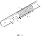
- FIG. 1B shows the stent delivery system 100 of FIG. 1A within the body lumen 180 and with the stent 105 fully deployed.
- the pusher 115 is advanced distally, as indicated by arrow 140, with respect to the outer sheath 110, or the outer sheath 110 is withdrawn proximally with respect to the pusher 115. Because the pusher 115 abuts against the stent 105, the stent 105 will be pushed from the distal end 125 of the outer sheath 110 as the pusher 115 is advanced distally or as the outer sheath 110 is withdrawn proximally. In the case of a self-expanding stent, the stent 105 expands to contact the inner surface of the body lumen 180 as it exits the outer sheath 110.
- FIG. 1C shows the stent 105 of FIGs. 1A-1B fully deployed within the body lumen 180 and with the stent delivery system 100 fully withdrawn from the body lumen 180.
- the outer sheath 110 and the pusher 115 are withdrawn back through the access site 185.
- the guidewire lumen 120 is also withdrawn back through the access site 185 and can be done so before, after, or at the same time as the outer sheath 110 and pusher 115.
- liquid from the lumen 180 may leak into the surrounding tissue. In the case of the common bile duct, bile leakage into the surrounding tissue may cause serious discomfort to the patient.
- the stent 105 may include a deployable member 130 that deploys from the stent body 135 of the stent 105 to cover the access site 185.
- the deployable member 130 increases the body lumen contact surface area of the stent 105.
- the deployable member 130 is generally coupled with the stent body 135 and remains attached to the stent body 135 after deployment.
- the deployable member 130 may deploy from the stent body 135 by hinging, unrolling, extending, expanding, or translating away from the stent body 135.
- the deployable member 130 may contact a partially circumferential portion of the body lumen 180 (as shown in FIG. 1C ) or may instead contact a fully circumferential portion.
- the deployable member 130 may include one or more separate elements that may be made from the same materials and construction as the stent body 135 or may instead be made from different materials or construction.
- the deployable member 130 may include a frame or scaffolding structure like the stent body 135. If made from a frame or scaffolding structure, the deployable member 130 may include a covering or webbing that at least partially prevents liquid from flowing through the deployable member 130. Additionally or alternatively, the frame or scaffolding may be densely arranged (e.g., a mesh) to at least partially prevent the flow of liquid therethrough.
- the deployable member 130 is a solid, unitary piece without a frame.
- the deployable member 130 may include materials with properties particularly suited for closing an access site 185 such materials that promote coagulation or healing, or materials that are absorbent or adherent.
- the deployable member 130 may be triggered to deploy during or after the stent delivery system 100 is withdrawn back through the access site 185.
- the deployable member 130 is constrained in a pre-deployed or stowed position by some component of the stent delivery system 100 or the stent 105, and by removing the stent delivery system 100 from the body lumen 180, the deployable member 130 is thereby unconstrained and will deploy to cover the access site 185.
- some component of the stent delivery system 100 may pull on or otherwise urge the deployable member 130 into the deployed position either during or after the stent delivery system 100 has been withdrawn from the body lumen 180.
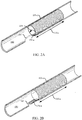
- FIG. 2A shows a fully deployed stent 105-a within a body lumen 180 in accordance with aspects of the present disclosure.
- the stent 105-a may be an example of the stent 105 of FIGs. 1A-1C .
- the stent 105-a includes a deployable member 130-a that is shown stowed within the stent body 135-a.
- the deployable member 130-a is a flap that is hingedly coupled with the stent body 135-a.
- the deployable member 130-a may deploy from the stent body 135-a by hinging, as indicated by arrow 205, from inside the stent body 135-a (as shown in FIG.
- the length of the deployable member 130-a is selected such that it clears the inner surface of the stent body 135-a as it hinges from inside to outside the stent body 135-a.
- the deployable member 130-a may be configured to spring open to the deployed configuration shown in FIG. 2B when unconstrained.
- the deployable member 130-a may be made from or include a material or component that stores elastic potential energy when in the stowed configuration.
- some component of the stent delivery system 100 e.g., the guidewire lumen 120 or the pusher 115
- the deployable member 130-a may hold the deployable member 130-a down in the stowed configuration while the stent delivery system 100 is still within the body lumen 180.
- the deployable member 130-a is free to spring open to the deployed configuration shown in FIG. 2B .
- the deployable member 130-a may be detachably connected with some component of the stent delivery system 100 by a pull string (e.g., a surgical suture).
- a pull string e.g., a surgical suture
- the deployable member 130-a is pulled into the deployed configuration shown in FIG. 2B by the stent delivery system 100 as it exits the access site 185.
- the connection between the stent delivery system 100 and the deployable member 130-a may be detached (e.g., breaking or otherwise disconnecting the pull string).
- the deployable member 130-a may include a frame or other support structure and may be made from the same material or materials as the stent body 135-a. In other examples, the deployable member 130-a is made from a different material than the stent body 135-a.
- the materials forming the structure of the deployable member 130-a may be densely arranged (e.g., mesh-like) so as to impede the flow of fluid through the deployable member 130-a.
- the deployable member 130-a may also include a web, coating, or some other covering (e.g., silicon, polyurethane, polytetrafluoroetheylene, fabric) that prevents or at least impedes the flow of fluid therethrough.
- FIG. 3A shows a fully deployed stent 105-b within a body lumen 180 in accordance with aspects of the present disclosure.
- the stent 105-b may be an example of the stent 105 described with reference to FIGs. 1A-1C .
- the stent 105-b includes a deployable member 130-b that is shown stowed within the stent body 135-b.
- the deployable member 130-b includes a plurality of flaps that are hingedly coupled with the stent body 135-b.
- the individual flaps of the deployable member 130-b may be an example of or include features of the single flap of the deployable member 130-a described with reference to FIGs. 2A-2B .
- the individual flaps of the deployable member 130-b may deploy from the stent body 135-b by hinging, as indicated by arrow 305, from inside the stent body 135-b (as shown in FIG. 3A ) to outside the stent body 135-b (as shown in FIG. 3B ), thereby increasing the body lumen contact surface area of the stent 105-b.
- the individual flaps of the deployable member 130-b may be equidistantly spaced around the circumference of the stent body 135-b. As such, once deployed, the deployable member 130-b provides coverage around a full circumference of the body lumen 180. Alternatively, the flaps may be spaced only around a partial circumference of the stent body 135-b. In such cases, the stent 105-b is radially aligned with respect to the body lumen 180 such that the deployable member 130-b covers the access site 185 when deployed. Depending on the number and size of the flaps of the deployable member 130-b, the flaps may at least partially overlap and therefore may deploy in serial fashion around the circumference of the stent body 135-b.
- the deployable member 130-b may be configured to spring open to the deployed configuration shown in FIG. 3B when unconstrained.
- the deployable member 130-b may be made from or include a material or component that stores elastic potential energy when in the stowed configuration.
- some component of the stent delivery system 100 e.g., the guidewire lumen 120 or the pusher 115
- the deployable member 130-b may hold the deployable member 130-b down in the stowed configuration while the stent delivery system 100 is still within the body lumen 180.
- the deployable member 130-b is free to spring open to the deployed configuration shown in FIG. 3B .
- the deployable member 130-b may be detachably connected with some component of the stent delivery system 100 by a pull string (e.g., a surgical suture).
- a pull string e.g., a surgical suture
- the deployable member 130-b is pulled into the deployed configuration shown in FIG. 3B by the stent delivery system 100 as it exits the access site 185.
- the connection between the stent delivery system 100 and the deployable member 130-b may be detached (e.g., breaking or otherwise disconnecting the pull string).
- the individual flaps of the deployable member 130-b may include a frame or other support structure and may be made from the same material or materials as the stent body 135-b. In other examples, the deployable member 130-b is made from a different material than the stent body 135-b.
- the materials forming the structure of the deployable member 130-b may be densely arranged (e.g., mesh-like) so as to impede the flow of fluid through the deployable member 130-b.
- the deployable member 130-b may also include a web, coating, or some other covering (e.g., silicon, polyurethane, polytetrafluoroetheylene, fabric) that prevents or at least impedes the flow of fluid therethrough.
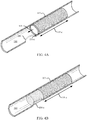
- FIG. 4A shows a fully deployed stent 105-c within a body lumen 180 in accordance with aspects of the present disclosure.
- the stent 105-c may be an example of the stent 105 described with reference to FIGs. 1A-1C .
- the stent 105-c includes a deployable member 130-c that is shown in a stowed configuration.
- the deployable member 130-c is a tube configured to expand and collapse like an accordion, and is coupled with the end of the stent body 135-c proximate the access site 185. In the stowed configuration, the deployable member 130-c is collapsed down as shown in FIG. 4A and may be partially or fully housed within the stent body 135-c.
- the deployable member 130-c may deploy from the stent body 135-c by extending in length axially away from the stent body 135-c (as shown by arrow 405) until it is elongated (as shown in FIG. 4B ), thereby increasing the body lumen contact surface area of the stent 105-c.
- the deployable member 130-c may be configured to spring open to the deployed configuration shown in FIG. 4B when unconstrained.
- the deployable member 130-c may be made from or include a material or component that stores elastic potential energy when in the stowed configuration.
- some component of the stent delivery system 100 e.g., the guidewire lumen 120 or the pusher 115
- the deployable member 130-c may hold the deployable member 130-c in the stowed configuration while the stent delivery system 100 is still within the body lumen 180.
- the deployable member 130-c is free to spring open to the deployed configuration shown in FIG. 4B .
- the deployable member 130-c may be detachably connected with some component of the stent delivery system 100 by a pull string (e.g., a surgical suture).
- a pull string e.g., a surgical suture
- the deployable member 130-c is pulled into the deployed configuration shown in FIG. 4B by the stent delivery system 100 as it exits the access site 185.
- the connection between the stent delivery system 100 and the deployable member 130-c may be detached (e.g., breaking or otherwise disconnecting the pull string).
- the deployable member 130-c may include a frame or other support structure and may be made from the same material or materials as the stent body 135-c. In other examples, the deployable member 130-c is made from a different material than the stent body 135-c.
- the materials forming the structure of the deployable member 130-c may be densely arranged (e.g., mesh-like) so as to impede the flow of fluid through the deployable member 130-c.
- the deployable member 130-c may also include a web, coating, or some other covering (e.g., silicon, polyurethane, polytetrafluoroetheylene, fabric) that prevents or at least impedes the flow of fluid therethrough.
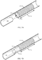
- FIG. 5A shows a fully deployed stent 105-d within a body lumen 180 in accordance with aspects of the present disclosure.
- the stent 105-d may be an example of the stent 105 described with reference to FIGs. 1A-1C .
- the stent 105-d includes a deployable member 130-d that is shown in a stowed configuration.
- the deployable member 130-d is a tube configured to expand and collapse like an accordion, and is coupled with the end of the stent body 135-d proximate the access site 185. In the stowed configuration, the deployable member 130-d is collapsed down as shown in FIG. 5A and may be partially or fully housed within the stent body 135-d.
- the deployable member 130-d may deploy from the stent body 135-d by extending in length axially away from the stent body 135-d, as indicated by arrow 505, until it is elongated (as shown in FIG. 5B ), thereby increasing the body lumen contact surface area of the stent 105-d.
- the deployable member 130-d may be configured to spring open to the deployed configuration shown in FIG. 5B when unconstrained.
- the deployable member 130-d may be made from a material that stores elastic potential energy when in the stowed configuration.
- the deployable member 130-d may include one or more integrated spring elements 510 that urge the deployable member 130-d to elongate axially.
- some component of the stent delivery system 100 e.g., the guidewire lumen 120 or the pusher 115
- the deployable member 130-d is free to spring open to the deployed configuration shown in FIG. 5B .
- the deployable member 130-d may be detachably connected with some component of the stent delivery system 100 by a pull string (e.g., a surgical suture).
- a pull string e.g., a surgical suture
- the deployable member 130-d is pulled into the deployed configuration shown in FIG. 5B by the stent delivery system 100 as it exits the access site 185.
- the connection between the stent delivery system 100 and the deployable member 130-d may be detached (e.g., breaking or otherwise disconnecting the pull string).
- the deployable member 130-d may include a frame or other support structure and may be made from the same material or materials as the stent body 135-d. In other examples, the deployable member 130-d is made from a different material than the stent body 135-d. The materials forming the structure of the deployable member 130-d may be densely arranged (e.g., mesh-like) so as to impede the flow of fluid through the deployable member 130-d.
- the deployable member 130-d may also include a web, coating, or some other covering (e.g., silicon, polyurethane, polytetrafluoroetheylene, fabric) that prevents or at least impedes the flow of fluid therethrough.
- the deployable member 130-d may be made from a relatively flimsy material that is held in a generally cylindrical shape by the integrated spring elements 510.
- FIG. 6A shows a fully deployed stent 105-e within a body lumen 180 in accordance with aspects of the present disclosure.
- the stent 105-e may be an example of the stent 105 described with reference to FIGs. 1A-1C .
- the stent 105-e includes a deployable member 130-e that is shown stowed within the stent body 135-e.
- the deployable member 130-e is a flexible sleeve. In the stowed configuration, the deployable member 130-e is folded inside the stent body 135-e as shown in FIG. 6A .
- the deployable member 130-e may deploy from the stent body 135-e, as indicated by arrow 605, by unrolling from inside the stent body 135-e (as shown in FIG. 6B ) until it is fully unrolled (as shown in FIG. 6C ), thereby increasing the body lumen contact surface area of the stent 105-e.
- the deployable member 130-e is detachably connected with a pull string 610 or some other pull mechanism which is coupled with the stent delivery system 100.
- a pull string 610 or some other pull mechanism which is coupled with the stent delivery system 100.
- the deployable member 130-e is pulled by the pull string 610 until it unrolls from inside the stent body 135-e to outside the stent body 135-e, as shown in the progressions from FIG. 6A to FIG. 6C .
- the pull string 610 may be detached from the deployable member 130-e or from the stent delivery system 100.
- the deployable member 130-e may include a frame or other support structure and may be made from the same material or materials as the stent body 135-e. In other examples, the deployable member 130-e is made from a different material than the stent body 135-e.
- the materials forming the structure of the deployable member 130-e may be densely arranged (e.g., mesh-like) so as to impede the flow of fluid through the deployable member 130-e.
- the deployable member 130-e may also include a web, coating, or some other covering (e.g., silicon, polyurethane, polytetrafluoroetheylene, fabric) that prevents or at least impedes the flow of fluid therethrough.
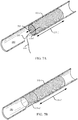
- FIG. 7A shows a fully deployed stent 105-f within a body lumen 180 in accordance with aspects of the present disclosure.
- the stent 105-f may be an example of the stent 105 described with reference to FIGs. 1A-1C .
- the stent 105-f includes a deployable member 130-f that is shown stowed within the stent body 135-f.
- the deployable member 130-f is a tubular member sized to fit inside the stent body 135-f.
- the deployable member 130-f is similar in structure and materials as the stent body 135-f, except with a smaller diameter.
- the deployable member 130-f is housed inside the stent body 135-f as shown in FIG. 7A .
- the distal end of the deployable member 130-f is attached to the proximal end of the stent body 135-f by a flexible cuff or sleeve.
- the deployable member 130-e may deploy from the stent body 135-f, as indicated by arrow 705, by translating coaxially with the stent body 135-f from inside the stent body 135-f (as shown in FIG. 6A ) to outside the stent body 135-f (as shown in FIG. 7B ), thereby increasing the body lumen contact surface area of the stent 105-f.
- the deployable member 130-f is detachably connected with a pull string 610 which is coupled with the stent delivery system 100.
- a pull string 610 which is coupled with the stent delivery system 100.
- the deployable member 130-f is pulled by the pull string 610 until it exits from inside the stent body 135-f to outside the stent body 135-f.
- the pull string 610 may be detached from the deployable member 130-f or from the stent delivery system 100.
- the deployable member 130-f may include a frame or other support structure and may be made from the same material or materials as the stent body 135-f. In other examples, the deployable member 130-f is made from a different material than the stent body 135-f.
- the materials forming the structure of the deployable member 130-f may be densely arranged (e.g., mesh-like) so as to impede the flow of fluid through the deployable member 130-f.
- the deployable member 130-f may also include a web, coating, or some other covering (e.g., silicon, polyurethane, polytetrafluoroetheylene, fabric) that prevents or at least impedes the flow of fluid therethrough.
- FIG. 8 shows a fully deployed stent 105-g within a body lumen 180 in accordance with aspects of the present disclosure.
- the stent 105-g may be an example of the stent 105 described with reference to FIGs. 1A-1C .
- the stent body 135-g is made from a helically wrapped wire-form construction.
- the stent body 135-g may instead be made from a laser-cut construction.
- the deployable member 130-g is made from a different construction, such as a braided stent construction.
- the wire-form or laser-cut stent body 135-g experiences less foreshortening when deployed from the stent delivery system 100 than a braided stent. As such, the stent body 135-g may be more accurately placed within the body lumen 180 across the target site (e.g., across the major duodenal papilla).
- the deployable member 130-g may be an example of or include features of any of the deployable members 135-c, 135-d, 135-e, or 135-f described with reference to FIGs. 4-7 .
- FIG. 9 shows a fully deployed stent 105-h within a body lumen 180 in accordance with aspects of the present disclosure.
- the stent 105-h includes a stent body 135-h and a deployable member 130-h.
- the stent 105-h and the deployable member 130-h may be an example of or include features of any of the stents 105 or deployable members 130 described with reference to FIGs. 1-8 .
- the stent 105-h may be configured to create a variable radial force profile across the length of the stent body 135-h.
- the radial compression exerted by the stent 105-h on the inner surface of the body lumen 180 may be greater at the distal end of the stent 105-h (with respect to the access site 185) than at the proximal end.
- the radial force is greater along a distal section 905 of the stent body 135-h than along a proximal section 910.
- a variable radial compression profile may improve stent migration resistance, long term stent patency, and reduce tumor ingrowth.
- the radial force profile is created by forming the distal portion 905 of the stent body 135-h with braided wires that are thicker than those along the proximal portion 910 (as illustrated by the darker lines in distal section 905).
- the thicker wires will be stiffer and therefore capable of exerting a greater expansion force.
- the wires in the proximal portion 910 may have a diameter in the range of 0.006 inches to 0.008 inches while the wires along the distal portion 905 may have a diameter in the range of 0.0075 inches to 0.010 inches.
- the distal section 905 may be made from a different material that is stiffer than the material used for the proximal section 910.
- the variable radial force is accomplished by forming the distal portion 905 with a wire-form or laser-cut construction, whereas the proximal portion 910 of the stent body 135-h is formed of a braided construction.
- two sections 905, 910 of varying radial expansion force are illustrated, it may be appreciated that more sections may be included to create a more linearly increasing force profile.
- a stent delivery system 1000 for placing a stent 105-i within a body lumen within the pancreaticobiliary system is illustrated in accordance with aspects of the present disclosure.
- the stent delivery system 1000 may be an example of the stent delivery system 100 described with reference to FIGs. 1A-1C
- the stent 105-i may be an example of or include features of any stent 105 described with reference to FIGs. 1-9 .
- the illustrated portions of the pancreaticobiliary system include the common bile duct 1005, which drains bile from the gallbladder 1030 into the duodenum 1015, where the bile mixes and reacts with digesting food. As shown, the common bile duct 1005 joins with the pancreatic duct 1020 at the major duodenal papilla 1010 (shown obstructed) before draining into the duodenum 1015.
- the drainage procedure generally includes a clinician advancing an endoscope 1025 (e.g., an EUS endoscope) into the lumen of a patient's duodenum 1015 to a position in which the bile ducts may be visualized (e.g., via endosonography).
- an endoscope 1025 e.g., an EUS endoscope
- the clinician may then access the common bile duct 1005 by advancing a needle or a cannula (not shown) from a working channel of the endoscope 1025, through the wall of the duodenum 1015 (i.e., trans-duodenally), and then through the wall of the common bile duct 1005, thereby creating an access site 185.
- the clinician may then advance a guidewire lumen 120-a through the access site 185, and then advance an outer sheath 110-a of the stent delivery system 1000 over the guidewire lumen 120-a and into the common bile duct 1005, thereby dilating the access site 185, as described with reference to FIG. 1B .
- the stent 105-i may deployed from the stent delivery system 1000 across the major duodenal papilla 1010 to restore normal flow through the common bile duct 1005.
- the deployable member 130-i may deploy from the body of stent 105-i to cover the access site 185.
- the deployable member 130-i may be an example of or include features of any deployable member 130 described with reference to FIGs. 1-9 .
- FIG. 12A illustrates a stent delivery system 1200-a with the stent 105-k retracted towards the access site 185 in accordance with aspects of the present disclosure.
- the stent 105-k may be pulled towards the access site 185 in a proximal direction, as indicated by arrow 1205.
- the stent 105-k may be pulled toward the access site 185 until the proximal portion 1210 of the stent 105-k at least partially covers the access site 185.
- the stent 105-k may be retracted towards the access site 185 by pulling the guidewire lumen 120 in a proximal direction.
- the stent 105-k may be pulled towards the access site 185 by pulling the hub 1215 of the guidewire lumen 120 in a proximal direction. In some cases, the stent 105-k may be pulled towards the access site 185 by pulling the hub 1215 of the guidewire lumen 120, the lumen member (not shown), and the outer sheath hub 1220 of the outer sheath 110.
- the stent 105-k may be repositioned within the body lumen 180 to at least partially cover the access site 185.
- a primary constrainment member 1230 may be released.
- the stent 105-k may be deployed by pulling the primary constrainment member 1230 in a proximal direction, pulling one or more tethers coupled with the primary constrainment member 1230, or both.
- the stent 105-k may be disposed onto the guidewire lumen 120 such that the guidewire lumen 120 is inside the stent 105-k along a distal portion of the stent 105-k and outside of the stent 105-k along the proximal portion 1210 of the stent 105-k.
- This configuration may be referred to a partial side-saddle configuration.
- FIG. 12B illustrates a stent delivery system 1200-b with the stent 105-k fully deployed in accordance with aspects of the present disclosure.
- the stent 105-k expands to contact the inner surface of the body lumen 180.
- the guidewire lumen 120 and the guidewire 1225 are withdrawn through the access site 185.
- the guidewire lumen 120 and the guidewire 1225 may extend through a hole in a wall of the stent 105-k. In such cases, the guidewire lumen 120 and the guidewire 1225 may be withdrawn through the hole in the wall of the stent 105-k.
- the hole in the wall of the stent may allow for fluid from the body lumen 180 to leak out into the surrounding tissue and organs.
- the stent 105-k may be in the partial side-saddle configuration, the hole in the stent 105-k may align with the access site 185.
- the system 1200-b may include a coverage member.
- the coverage member may be configured to at least partially cover the hole in the wall of the stent 105-k upon withdrawing the guidewire lumen 120 through the hole in the wall of the stent 105-k, thereby at least partially sealing the access site 185 and preventing the leakage of fluid from the body lumen 180.
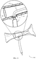
- FIG. 13 illustrates a stent delivery system 1300 with a stent 105-I with a flap valve in accordance with aspects of the present disclosure.
- the coverage member 1305 may at least partially cover the hole in the wall of the stent 105-I.
- the coverage member 1305 may be an example of a flap valve.
- the flap valve may be configured to seal the hole in the wall of the stent 105-I when the guidewire lumen 120 is withdrawn through the hole in the wall of the stent 105-I.
- the flap valve may be a one-way control valve.
- the flap valve may be positioned on an inner diameter of the stent 105-I.
- the flap valve may include one or more flaps spaced around a circumference of the hole in the wall of the stent 105-I such that the one or more flaps may align to form a closed flap valve.
- FIG. 14 illustrates a stent delivery system 1400 with a stent 105-m with a hinged valve in accordance with aspects of the present disclosure.
- the coverage member 1405 may at least partially cover the hole in the wall of the stent 105-m.
- the coverage member 1405 may be an example of a hinged valve.
- the hinged valve may be configured to hinge such that when the guidewire lumen 120 is withdrawn through the hole in the wall of the stent 105-m, the hole in the wall of the stent 105-m may be covered.
- the hinged valve may rotate on an axis to remain open when the guidewire lumen 120 is positioned through the hole in the wall of the stent 105-m and closed when the guidewire lumen 120 is withdrawn through the hole in the wall of the stent 105-m.
- the hinged valve may be spring-loaded such that the hinged valve recoils when the guidewire lumen 120 is withdrawn through the hole.
- the hinged valve may be made from or include a material or component that stores elastic potential energy when the guidewire lumen 120 is positioned through the hole in the wall of the stent 105-m.
- the stent delivery system 1400 may include a polymer jacket 1410 disposed on the outer surface of a central portion of the stent 105-m. In such cases, the hinged valve may be coupled to the polymer jacket 1410.
- FIG. 15 illustrates a stent delivery system 1500 with a stent 105-n with a self-sealing membrane in accordance with aspects of the present disclosure.
- the coverage member 1505 may at least partially cover the hole in the wall of the stent 105-n.
- the coverage member 1505 may be an example of a self-sealing membrane material disposed on an outer surface of the wall of the stent 105-n.
- the self-sealing membrane material may be configured to seal the hole in the wall of the stent 105-n when the guidewire lumen 120 is withdrawn through the hole in the wall of the stent 105-n.
- the self-sealing membrane material may include a pin hole that closes to a diameter to prevent bile leakage.
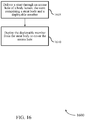
- FIG. 16 shows a flowchart illustrating a method 1600 for stenting a body lumen 180 in accordance with various aspects of the present disclosure.
- the steps of method 1600 may be performed with any of the systems or components described with reference to FIGs. 1-11 and may be an example of aspects of the particular procedure described with reference to FIGs. 10-11 .
- the method 1600 may include delivering a stent 105 through an access site 185 of a body lumen 180.
- the stent 105 may comprise a stent body 135 and a deployable member 130.
- the method 1600 may further include deploying the deployable member 130 from the stent body 135 to cover the access site 185.
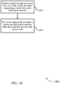
- FIG. 17 shows a flowchart illustrating a method 1700 for stenting a body lumen 180 in accordance with various aspects of the present disclosure.
- the steps of method 1700 may be performed with any of the systems or components described with reference to FIGs. 1-11 and may be an example of aspects of the particular procedure described with reference to FIGs. 10-11 .
- the method 1700 may include delivering a stent 105 through an access site 185 of a body lumen 180.
- the stent 105 may comprise a stent body 135 and a deployable member 130.
- the method 1300 may further include releasing the deployable member 130 from a constrained configuration to deploy the deployable member 130 from the stent body 135 to cover the access site 185.
- FIG. 18 shows a flowchart illustrating a method 1800 for stenting a body lumen 180 in accordance with various aspects of the present disclosure.
- the steps of method 1400 may be performed with any of the systems or components described with reference to FIGs. 1-11 and may be an example of aspects of the particular procedure described with reference to FIGs. 10-11 .
- the method 1800 may include delivering a stent 105 through an access site 185 of a body lumen 180.
- the stent 105 may comprise a stent body 135 and a deployable member 130.
- the method 1800 may further include pulling on the deployable member 130 to deploy the deployable member 130 from the stent body 135 to cover the access site 185.
Landscapes
- Health & Medical Sciences (AREA)
- Engineering & Computer Science (AREA)
- Biomedical Technology (AREA)
- Cardiology (AREA)
- Oral & Maxillofacial Surgery (AREA)
- Transplantation (AREA)
- Heart & Thoracic Surgery (AREA)
- Vascular Medicine (AREA)
- Life Sciences & Earth Sciences (AREA)
- Animal Behavior & Ethology (AREA)
- General Health & Medical Sciences (AREA)
- Public Health (AREA)
- Veterinary Medicine (AREA)
- Gastroenterology & Hepatology (AREA)
- Pulmonology (AREA)
- Media Introduction/Drainage Providing Device (AREA)
- Physics & Mathematics (AREA)
- Optics & Photonics (AREA)
- Prostheses (AREA)
Applications Claiming Priority (1)
| Application Number | Priority Date | Filing Date | Title |
|---|---|---|---|
| US16/242,587 US11207172B2 (en) | 2019-01-08 | 2019-01-08 | Stent designs to cover catheter access site |
Publications (2)
| Publication Number | Publication Date |
|---|---|
| EP3679902A2 true EP3679902A2 (de) | 2020-07-15 |
| EP3679902A3 EP3679902A3 (de) | 2020-09-16 |
Family
ID=69172593
Family Applications (1)
| Application Number | Title | Priority Date | Filing Date |
|---|---|---|---|
| EP20150480.0A Pending EP3679902A3 (de) | 2019-01-08 | 2020-01-07 | Stentdesigns zur abdeckung einer katheterzugangsstelle |
Country Status (5)
| Country | Link |
|---|---|
| US (2) | US11207172B2 (de) |
| EP (1) | EP3679902A3 (de) |
| JP (1) | JP7465095B2 (de) |
| CN (1) | CN111419491A (de) |
| AU (1) | AU2019283821A1 (de) |
Cited By (2)
| Publication number | Priority date | Publication date | Assignee | Title |
|---|---|---|---|---|
| US11207172B2 (en) | 2019-01-08 | 2021-12-28 | Covidien Lp | Stent designs to cover catheter access site |
| EP4335387A1 (de) * | 2022-09-09 | 2024-03-13 | Caranx Medical SAS | Endoluminale vorrichtung und verfahren zum verschliessen einer öffnung in einer rohrförmigen struktur eines patienten |
Families Citing this family (3)
| Publication number | Priority date | Publication date | Assignee | Title |
|---|---|---|---|---|
| CA3172361A1 (en) * | 2020-02-26 | 2021-09-02 | Boston Scientific Scimed, Inc. | Endoluminal sealing devices and related methods of use |
| WO2021234638A1 (en) * | 2020-05-20 | 2021-11-25 | Puzzle Medical Devices Inc. | Implantable fully endovascular mammalian body succedent cavity wall breach sealing device |
| US12357481B2 (en) * | 2021-02-22 | 2025-07-15 | Stryker Corporation | Implant delivery devices and methods of making the same |
Family Cites Families (14)
| Publication number | Priority date | Publication date | Assignee | Title |
|---|---|---|---|---|
| NL1014559C2 (nl) * | 2000-02-11 | 2001-08-14 | Surgical Innovations Vof | Umbrella-stent. |
| US9101500B2 (en) * | 2005-01-10 | 2015-08-11 | Trireme Medical, Inc. | Stent with self-deployable portion having wings of different lengths |
| WO2008027366A2 (en) * | 2006-08-28 | 2008-03-06 | Vascular Precision | Devices and methods for creating and closing controlled openings in tissue |
| US20090270971A1 (en) * | 2008-04-24 | 2009-10-29 | Medtronic Vascular, Inc. | Prosthesis Fixation Apparatus and Methods |
| WO2010064244A2 (en) * | 2008-12-04 | 2010-06-10 | Inverthis Ltd | Delivery system for delivering a graft from the middle thereof |
| WO2011004374A1 (en) | 2009-07-09 | 2011-01-13 | Endospan Ltd. | Apparatus for closure of a lumen and methods of using the same |
| WO2011067756A1 (en) | 2009-12-02 | 2011-06-09 | X-Seal Technologies Ltd. | Device system and method for tissue access site closure |
| US9044313B2 (en) * | 2010-10-08 | 2015-06-02 | Kfx Medical Corporation | System and method for securing tissue to bone |
| EP2497426B1 (de) | 2011-03-09 | 2016-12-14 | Aeeg Ab | Vorrichtung und Kit zum Verschließen einer Körperlumenpunktur |
| US20130197657A1 (en) | 2011-12-08 | 2013-08-01 | Diana Anca | Central airway stent |
| EP3258891A1 (de) * | 2015-02-20 | 2017-12-27 | Boston Scientific Scimed, Inc. | Stent mit zurückziehbaren ankern |
| CN107822739B (zh) * | 2016-09-07 | 2020-03-24 | 先健科技(深圳)有限公司 | 管腔支架及管腔支架系统 |
| US10980635B2 (en) * | 2018-01-07 | 2021-04-20 | William Joseph Drasler | Annuloplasty device and methods |
| US11207172B2 (en) | 2019-01-08 | 2021-12-28 | Covidien Lp | Stent designs to cover catheter access site |
-
2019
- 2019-01-08 US US16/242,587 patent/US11207172B2/en active Active
- 2019-12-17 AU AU2019283821A patent/AU2019283821A1/en not_active Abandoned
-
2020
- 2020-01-07 JP JP2020000942A patent/JP7465095B2/ja active Active
- 2020-01-07 EP EP20150480.0A patent/EP3679902A3/de active Pending
- 2020-01-08 CN CN202010017307.8A patent/CN111419491A/zh active Pending
-
2021
- 2021-11-17 US US17/528,696 patent/US20220071759A1/en not_active Abandoned
Cited By (2)
| Publication number | Priority date | Publication date | Assignee | Title |
|---|---|---|---|---|
| US11207172B2 (en) | 2019-01-08 | 2021-12-28 | Covidien Lp | Stent designs to cover catheter access site |
| EP4335387A1 (de) * | 2022-09-09 | 2024-03-13 | Caranx Medical SAS | Endoluminale vorrichtung und verfahren zum verschliessen einer öffnung in einer rohrförmigen struktur eines patienten |
Also Published As
| Publication number | Publication date |
|---|---|
| US20220071759A1 (en) | 2022-03-10 |
| US11207172B2 (en) | 2021-12-28 |
| CN111419491A (zh) | 2020-07-17 |
| AU2019283821A1 (en) | 2020-07-23 |
| JP7465095B2 (ja) | 2024-04-10 |
| EP3679902A3 (de) | 2020-09-16 |
| US20200214861A1 (en) | 2020-07-09 |
| JP2020110584A (ja) | 2020-07-27 |
Similar Documents
| Publication | Publication Date | Title |
|---|---|---|
| EP3679902A2 (de) | Stentdesigns zur abdeckung einer katheterzugangsstelle | |
| US12490985B2 (en) | Flow control valve | |
| KR102812134B1 (ko) | 담관 스텐트 | |
| EP1689324B1 (de) | Gefässimplantat | |
| US9687242B2 (en) | Occlusion device | |
| CN110063825B (zh) | 腔内装置 | |
| US20060253190A1 (en) | Removeable stents | |
| US11944560B2 (en) | Expandable stent delivery apparatus to cover an access site | |
| CN111407479B (zh) | 用于覆盖穿刺部位的可旋转支架递送设备 | |
| US12036139B2 (en) | Apparatuses for stent delivery and positioning to cover an access site | |
| EP4215166A1 (de) | Transluminales stentzuführ- und positionssystem | |
| EP4465900A1 (de) | Vorrichtungen zur stenteinbringung und positionierung zur transluminalen anwendung | |
| US20230233312A1 (en) | Stent design for transluminal application | |
| JP2026511780A (ja) | 埋込型デバイスの位置を制御するためのデバイス、システム及び方法 | |
| JP2025506021A (ja) | 係合可能なステントのための器具、システム及び方法 |
Legal Events
| Date | Code | Title | Description |
|---|---|---|---|
| PUAI | Public reference made under article 153(3) epc to a published international application that has entered the european phase |
Free format text: ORIGINAL CODE: 0009012 |
|
| STAA | Information on the status of an ep patent application or granted ep patent |
Free format text: STATUS: THE APPLICATION HAS BEEN PUBLISHED |
|
| AK | Designated contracting states |
Kind code of ref document: A2 Designated state(s): AL AT BE BG CH CY CZ DE DK EE ES FI FR GB GR HR HU IE IS IT LI LT LU LV MC MK MT NL NO PL PT RO RS SE SI SK SM TR |
|
| AX | Request for extension of the european patent |
Extension state: BA ME |
|
| RIN1 | Information on inventor provided before grant (corrected) |
Inventor name: HAMILTON, DAVID H. Inventor name: KARASEK, DAVID J. Inventor name: MAGUIRE, MARK, A. Inventor name: MCWEENEY, JOHN O. Inventor name: DANIEL, SHAWN C Inventor name: BARTFIELD, SCOTT Inventor name: TINKHAM, BRIAN Inventor name: HUSZAR, HILLARY K. |
|
| PUAL | Search report despatched |
Free format text: ORIGINAL CODE: 0009013 |
|
| AK | Designated contracting states |
Kind code of ref document: A3 Designated state(s): AL AT BE BG CH CY CZ DE DK EE ES FI FR GB GR HR HU IE IS IT LI LT LU LV MC MK MT NL NO PL PT RO RS SE SI SK SM TR |
|
| AX | Request for extension of the european patent |
Extension state: BA ME |
|
| RIC1 | Information provided on ipc code assigned before grant |
Ipc: A61F 2/82 20130101AFI20200811BHEP |
|
| STAA | Information on the status of an ep patent application or granted ep patent |
Free format text: STATUS: REQUEST FOR EXAMINATION WAS MADE |
|
| 17P | Request for examination filed |
Effective date: 20210315 |
|
| RBV | Designated contracting states (corrected) |
Designated state(s): AL AT BE BG CH CY CZ DE DK EE ES FI FR GB GR HR HU IE IS IT LI LT LU LV MC MK MT NL NO PL PT RO RS SE SI SK SM TR |
|
| GRAP | Despatch of communication of intention to grant a patent |
Free format text: ORIGINAL CODE: EPIDOSNIGR1 |
|
| STAA | Information on the status of an ep patent application or granted ep patent |
Free format text: STATUS: GRANT OF PATENT IS INTENDED |
|
| INTG | Intention to grant announced |
Effective date: 20240926 |
|
| GRAJ | Information related to disapproval of communication of intention to grant by the applicant or resumption of examination proceedings by the epo deleted |
Free format text: ORIGINAL CODE: EPIDOSDIGR1 |
|
| STAA | Information on the status of an ep patent application or granted ep patent |
Free format text: STATUS: REQUEST FOR EXAMINATION WAS MADE |
|
| INTC | Intention to grant announced (deleted) | ||
| GRAP | Despatch of communication of intention to grant a patent |
Free format text: ORIGINAL CODE: EPIDOSNIGR1 |
|
| STAA | Information on the status of an ep patent application or granted ep patent |
Free format text: STATUS: GRANT OF PATENT IS INTENDED |
|
| INTG | Intention to grant announced |
Effective date: 20250103 |
|
| GRAJ | Information related to disapproval of communication of intention to grant by the applicant or resumption of examination proceedings by the epo deleted |
Free format text: ORIGINAL CODE: EPIDOSDIGR1 |
|
| STAA | Information on the status of an ep patent application or granted ep patent |
Free format text: STATUS: REQUEST FOR EXAMINATION WAS MADE |
|
| STAA | Information on the status of an ep patent application or granted ep patent |
Free format text: STATUS: EXAMINATION IS IN PROGRESS |
|
| INTC | Intention to grant announced (deleted) | ||
| 17Q | First examination report despatched |
Effective date: 20250527 |