EP3679874B1 - Retrieval device - Google Patents
Retrieval device Download PDFInfo
- Publication number
- EP3679874B1 EP3679874B1 EP20152855.1A EP20152855A EP3679874B1 EP 3679874 B1 EP3679874 B1 EP 3679874B1 EP 20152855 A EP20152855 A EP 20152855A EP 3679874 B1 EP3679874 B1 EP 3679874B1
- Authority
- EP
- European Patent Office
- Prior art keywords
- connection
- loop
- net
- net element
- leg portions
- Prior art date
- Legal status (The legal status is an assumption and is not a legal conclusion. Google has not performed a legal analysis and makes no representation as to the accuracy of the status listed.)
- Active
Links
- 239000000463 material Substances 0.000 claims description 9
- 230000009471 action Effects 0.000 claims description 5
- 230000033001 locomotion Effects 0.000 description 21
- 238000000034 method Methods 0.000 description 10
- 208000037062 Polyps Diseases 0.000 description 7
- 210000003238 esophagus Anatomy 0.000 description 5
- 238000004519 manufacturing process Methods 0.000 description 5
- 238000002788 crimping Methods 0.000 description 3
- 238000013461 design Methods 0.000 description 3
- 210000003811 finger Anatomy 0.000 description 3
- -1 for example Substances 0.000 description 3
- 210000000232 gallbladder Anatomy 0.000 description 3
- 238000009941 weaving Methods 0.000 description 3
- 239000004677 Nylon Substances 0.000 description 2
- 210000001015 abdomen Anatomy 0.000 description 2
- 230000006978 adaptation Effects 0.000 description 2
- 238000004873 anchoring Methods 0.000 description 2
- 238000013016 damping Methods 0.000 description 2
- 208000037265 diseases, disorders, signs and symptoms Diseases 0.000 description 2
- 230000000694 effects Effects 0.000 description 2
- 208000001130 gallstones Diseases 0.000 description 2
- 239000003562 lightweight material Substances 0.000 description 2
- 238000012986 modification Methods 0.000 description 2
- 230000004048 modification Effects 0.000 description 2
- 229920001778 nylon Polymers 0.000 description 2
- 230000000717 retained effect Effects 0.000 description 2
- 238000001356 surgical procedure Methods 0.000 description 2
- 210000003813 thumb Anatomy 0.000 description 2
- 239000010963 304 stainless steel Substances 0.000 description 1
- 229910000589 SAE 304 stainless steel Inorganic materials 0.000 description 1
- 239000000853 adhesive Substances 0.000 description 1
- 230000001070 adhesive effect Effects 0.000 description 1
- 230000000712 assembly Effects 0.000 description 1
- 238000000429 assembly Methods 0.000 description 1
- 230000004323 axial length Effects 0.000 description 1
- 238000005452 bending Methods 0.000 description 1
- 230000009286 beneficial effect Effects 0.000 description 1
- 230000005540 biological transmission Effects 0.000 description 1
- 230000008859 change Effects 0.000 description 1
- 201000001883 cholelithiasis Diseases 0.000 description 1
- 210000001072 colon Anatomy 0.000 description 1
- 238000010276 construction Methods 0.000 description 1
- 238000007796 conventional method Methods 0.000 description 1
- 230000001419 dependent effect Effects 0.000 description 1
- 201000010099 disease Diseases 0.000 description 1
- 208000035475 disorder Diseases 0.000 description 1
- 238000011065 in-situ storage Methods 0.000 description 1
- 238000003780 insertion Methods 0.000 description 1
- 230000037431 insertion Effects 0.000 description 1
- 238000002686 lithotriptor Methods 0.000 description 1
- 230000007246 mechanism Effects 0.000 description 1
- 239000002184 metal Substances 0.000 description 1
- 230000003287 optical effect Effects 0.000 description 1
- 210000000056 organ Anatomy 0.000 description 1
- 230000002093 peripheral effect Effects 0.000 description 1
- 239000004033 plastic Substances 0.000 description 1
- 230000008569 process Effects 0.000 description 1
- 239000012858 resilient material Substances 0.000 description 1
- 239000007787 solid Substances 0.000 description 1
- 210000002784 stomach Anatomy 0.000 description 1
- 210000003437 trachea Anatomy 0.000 description 1
- 238000002627 tracheal intubation Methods 0.000 description 1
Images

Classifications
-
- A—HUMAN NECESSITIES
- A61—MEDICAL OR VETERINARY SCIENCE; HYGIENE
- A61B—DIAGNOSIS; SURGERY; IDENTIFICATION
- A61B17/00—Surgical instruments, devices or methods, e.g. tourniquets
- A61B17/22—Implements for squeezing-off ulcers or the like on the inside of inner organs of the body; Implements for scraping-out cavities of body organs, e.g. bones; Calculus removers; Calculus smashing apparatus; Apparatus for removing obstructions in blood vessels, not otherwise provided for
- A61B17/221—Gripping devices in the form of loops or baskets for gripping calculi or similar types of obstructions
-
- A—HUMAN NECESSITIES
- A61—MEDICAL OR VETERINARY SCIENCE; HYGIENE
- A61B—DIAGNOSIS; SURGERY; IDENTIFICATION
- A61B17/00—Surgical instruments, devices or methods, e.g. tourniquets
- A61B17/00234—Surgical instruments, devices or methods, e.g. tourniquets for minimally invasive surgery
- A61B2017/00287—Bags for minimally invasive surgery
-
- A—HUMAN NECESSITIES
- A61—MEDICAL OR VETERINARY SCIENCE; HYGIENE
- A61B—DIAGNOSIS; SURGERY; IDENTIFICATION
- A61B17/00—Surgical instruments, devices or methods, e.g. tourniquets
- A61B17/22—Implements for squeezing-off ulcers or the like on the inside of inner organs of the body; Implements for scraping-out cavities of body organs, e.g. bones; Calculus removers; Calculus smashing apparatus; Apparatus for removing obstructions in blood vessels, not otherwise provided for
- A61B17/22031—Gripping instruments, e.g. forceps, for removing or smashing calculi
- A61B2017/22035—Gripping instruments, e.g. forceps, for removing or smashing calculi for retrieving or repositioning foreign objects
-
- A—HUMAN NECESSITIES
- A61—MEDICAL OR VETERINARY SCIENCE; HYGIENE
- A61B—DIAGNOSIS; SURGERY; IDENTIFICATION
- A61B17/00—Surgical instruments, devices or methods, e.g. tourniquets
- A61B17/22—Implements for squeezing-off ulcers or the like on the inside of inner organs of the body; Implements for scraping-out cavities of body organs, e.g. bones; Calculus removers; Calculus smashing apparatus; Apparatus for removing obstructions in blood vessels, not otherwise provided for
- A61B17/221—Gripping devices in the form of loops or baskets for gripping calculi or similar types of obstructions
- A61B2017/2212—Gripping devices in the form of loops or baskets for gripping calculi or similar types of obstructions having a closed distal end, e.g. a loop
Definitions
- the present invention relates to a retrieval device and to an endoscopic retrieval device for retrieving objects from within a human subject.
- Endoscopic retrieval or removal devices are known in the art and are conventionally used to recover objects from inside a human subject. Such objects may include severed human tissue, foreign objects, or food bolus. Some typical devices include forceps or clasps to grab objects.
- US 2003/004538A1 discloses an endoscopic surgical device for retrieving severed tissue or foreign bodies from within a subject.
- the device comprises a support unit and a tissue retrieving net system.
- the net system is carried by the support unit and may be inserted into the subject through an orifice or small incision and operated to retrieve tissue that has been severed by a conventional method.
- the net system comprises a net, a net actuator, a net deployment and retrieval assembly for transmitting motion between the net and its actuator.
- the net system further comprises at least one net connector disposed such that only one connector is within an articulation zone, defined by locations of severe bending of the device during operation.
- US 2005/267489A1 discloses an endoscopic surgical device for retrieving objects, such as for example, severed human tissue, foreign objects or impacted food bolus, from within a subject is disclosed.
- the device includes a body and handle movable relative to the body, a tubular member fixed to the body, a link having a first end fixed to the handle and a second end remote from the body, and a net including a loop and a net element.
- the loop is expandable and collapsible by action of the handle relative to the body.
- the loop retains an expanded configuration when deployed to allow for the capture certain objects that were otherwise difficult to capture because of positioning, location, or object characteristics.
- the loop may be constructed of flat wire and form a polygon shape when deployed. Structure at the distal end of the loop may propel and retain the loop into an open position when in use in narrow organs such as the esophagus.
- US 5,906,621A discloses an endoscopic surgical device for severing tissue within a subject and for retrieving severed tissue from within the subject is disclosed.
- the device has a support unit, a tissue severing snare system, and a tissue retrieving net system.
- the snare and net systems are carried by the support unit and may be inserted into the subject through an orifice or small incision and individually operated to sever and retrieve tissue.
- the snare system includes a snare, a snare actuator, and a snare deployment and retrieval assembly for transmitting motion between the actuator and the snare.
- the net system includes a net, a net actuator, a net deployment and retrieval assembly for transmitting motion between the net and its actuator and a net controller for assuring the net is fully opened when deployed.
- US 5,098,441A discloses a lithotriptor with a catch basket which is formed by a plurality of outwardly curved catch strings made of wire material and which comprises a catch basket foot and a catch basket top to which the catch strings are fixed to each other, the catch strings being connected at the catch basket foot to a pull string which consists of a plurality of pull wires and which is guided in a casing, the pull string being slidably arranged in the casing by means of a pull mechanism for introducing and retracting the catch basket.
- the pull string is formed by a wire rope being stranded at least twice, the number of strands of which corresponds to at least the number of catch strings of the catch basket, wherein the catch strings are formed by deformed rope strands of the wire rope which continuously run from the wire rope up to the top of the catch basket.
- US 5,147,371A discloses a device for the in situ collection of surgically excised material, including whole gall bladder, gallstones, dissected gall bladder and other tissues, for removal from the body, particularly in laproscopic surgical procedures.
- the gallstone removal device is an elongated tube for insertion through a trocar sheath into the abdomen of a patient during gallbladder surgery.
- a single wire doubly traverses the tube, forming a full loop, preferably a double loop, at the end of the tubing inserted into the abdomen.
- a bag or pouch extends from the wire loop which is tethered to the tube, and the loop and attached pouch are caused to open and close by manipulation of the wire.
- US 5,190,542A discloses surgical instrument assembly for use in snare cauterization operations comprises a tubular sheath member, a metallic cauterization loop, and a metal wire operatively connected to the loop, the wire passing longitudinally through the sheath.
- An electrical supply is operatively connectable to the wire for feeding an electrical current to the loop via the wire, while a manually actuatable shifter is operatively connected to the wire for longitudinally sliding the wire along the sheath in alternately opposite directions.
- a flexible web member is connected to the loop to form a capture pocket, the loop defining a mouth opening of the pocket.
- the loop is at least partially expanded from a collapsed configuration and passed over a polyp to be removed, so that the web member substantially surrounds the selected polyp.
- the loop is then closed to engage the polyp around a base region thereof and an electrical current is subsequently conducted through the loop to burn through the polyp at the base region thereof. Severance of the polyp occurs upon a closure of the cauterization loop by its being withdrawn or retracted into the tubular sheath member. The severed polyp is automatically captured by the web member.
- Certain devices of the above types may not be well-suited for retrieving rounded or blunt foreign objects such as coins, marbles and batteries because they are difficult to hold secure. Further, if a foreign object is dropped near the trachea during the removal process the results can be catastrophic for the patient.
- Many retrieval devices are used within an instrument channel of an endoscope during endoscopic medical procedures. These devices are generally expandable and collapsible relative to a tube inserted into the instrument channel. For example, a wire loop at the distal end of the device ma y expand and collapse relative to the tube by action of a handle at the proximal end of the device. Further, a net may be secured to the expandable and collapsible wire loop.
- a device for retrieving objects such as for example, impacted food bolus, foreign objects, and severed human tissue.
- the device is for use within an instrument channel of an endoscope during endoscopic medical procedures.
- the device includes a body, a handle fixed to and movable relative to the body, an elongated tube fixed to the body, a link extending substantially through the tube and having a first end fixed to the handle and a second end remote from the body, and a net including a loop and a net element.
- the loop is expandable and collapsible by action of the handle relative to the body.
- the net is secured at distal and proximal locations relative to the handle.
- the device is more reliable, structurally simpler, and less costly to manufacture than prior devices.
- a device for retrieving an object from within a human subject is disclosed.
- distal and proximal are used with respect to the operator's hand.
- the proximal and distal orientation are relative to the position of the surgeon or operator of the device.
- first connection, second connection, third connection, and the like do not imply a manufacturing order.
- attach (attached), connect (connected), and link (linked) are not limited to direct attachment, connection, or linking but also include indirect attachment, connection, or linking with intermediate parts, components, or assemblies being located between the two parts being attached, connected, or linked to one another.
- attach (attached), connect (connected), and link (linked) may include two parts integrally formed or unitarily constructed.
- the invention will be discussed in regard to a device designed for use within an endoscope for retrieving objects within relatively tight passages, such as for example, impacted food bolus from the esophagus. It should be apparent to others with ordinary skill in the art that the discussion and Figures included in this application are by way of example only, and that the invention can be utilized with endoscopic retrieval devices having a wide variety of structures, shapes, strengths, or purposes. One of many other exemplary uses for the invention is to remove polyps from the colon.
- netting As mentioned, devices using netting have been developed to capture rounded or blunt objects. In the use of devices having netting, and it is believed in the use of other devices, physicians have experienced difficulty in recovering certain objects, such as for example, impacted food bolus from the esophagus.
- a bolus is a mass of masticated or chewed food. In some cases, the bolus becomes impacted in the esophagus due to disease or other disorders and consequently does not pass into the stomach. It may be more difficult to position a net over an object of this type or the object may be heavier than the human tissue or foreign object for which a typical net device was originally designed. This problem is especially apparent when manipulating the device in relatively tight places within the body. As a result, netting support collapses and does not retain its shape in a deployed position when holding the captured object. Further, the netting may tear or net connections may fail causing reliability concerns.
- the retrieval device of the invention is more reliable, structurally simpler, and less costly to manufacture than prior devices.
- the proximal portion of the net element is secured to the wire that forms the loop and leg portions of the retrieval net using a shorter tether or anchor than previous designs which anchor the net element at a more proximal location.
- no tether or anchor is used to secure the proximal portion of the net element and instead the net element is routed between welds, or other similar connections, connecting the leg portions of the wire together. Were no tether is used to secure the proximal portion of the net element, the chances of the net element breaking or tearing are reduced because the forces are distributed more evenly over a greater area instead of at an isolated point of contact.
- the proximal portion of the net element at least partially surrounds the connection of the leg portions to the cable and/or the connection securing the leg portions together.
- the proximal portion of the net element inhibits damage to the connections and the inside of the tubular member.
- the proximal portion of the net element also provides a damping effect on the cable movement toward the distal end of the tubular member when the handle is activated. This also provides more control over the deployment of the net and cable and controls the portion of the device that exits the opening of the tubular member when the retrieval net is in the deployed position.
- the proximal portion of the net element also helps to center the leg portions of the wire and the cable within the tubular member.
- the retrieval net generally collapses and expands relative to a tube inserted through the instrument channel of the endoscope. In the collapsed position, the retrieval net is small enough in diameter to fit inside at least the distal end of a lumen of the tubing. Further, any connection securing the net element to the loop should be small enough to fit within the lumen and allow the retrieval net to collapse and expand repeatedly. The connection should also be able to hold the net element in place relative to the loop during the expansion and collapse of the retrieval net. Further, the loop is generally connected to a motion transmitting link. The motion transmitting link allows the loop to be manipulated by a handle at the proximal end of the device.
- any connection or connections securing the loop to the motion transmitting link must also be small enough to fit within the lumen and allow the retrieval net to collapse and expand repeatedly. If either of these connections is too large, the connection may drag or catch on the inside wall of the lumen. The friction between the connection and the inside wall of the lumen may prohibit essentially a 1:1 ratio between the movement of the handle and the movement of the distal end of the loop or retrieval net.
- the net element is generally supported by the loop by threading, or weaving, the flat wire through the holes in the net element.
- the net element may be supported by the loop by any suitable method known in the art.
- the net element may wrap around the loop, like a sleeve, or be tied to the loop.
- the net element may be secured to the wire by tethers, anchors, adhesives, or the like such that the net element is held in place relative to the loop during the expansion and collapse of the retrieval net.
- tethers or anchors may be used to secure the net element to the distal end and the proximal end of the loop.
- the proximal portion of the net element is attached adjacent a connection securing the two leg portions together, by a tether or anchor, such as for example, a string tie.
- the proximal portion of the net element may be attached using a tether or anchor to the proximal side of the connection securing the two leg portion together.
- the proximal portion of the net element may be attached using a tether or anchor to a 360 degree curved portion of at least one leg portion.
- the distal portion of the net element may also be attached using a tether or anchor to a 360 degree curved portion of the loop portion.
- the proximal portion of the net element may be secured to the leg portions by routing the net element through connections securing the two leg portions together.
- the size and smooth or curved contour of these connections reduce the drag or friction on the inside wall of the lumen, permitting essentially a 1:1 ratio between the movement of the handle and the movement of the distal end of the loop or retrieval net.
- FIG. 1 is a perspective view of a retrieval device 10 constructed in accordance with an embodiment of the disclosure not falling within the scope of the claimed invention.
- the device 10 includes a support base or elongated body 14.
- the body 14 includes a ring 16 at a proximal end.
- the device 10 also includes a handle 18 having two rings 20.
- the handle 18 is mounted over an interior section 15 of the body 14 and is movable relative to the body in the direction A 1 as illustrated, or in an opposing direction.
- an operator may place a finger in each of the rings 20 and thumb of the same hand in the body ring 16.
- the handle 18 can be slid in a direction opposite A 1 by pulling one's fingers towards one's thumb.
- the device 10 includes an elongated introducer member or tubular member 24 having a first end 26 fixed to the body 14 and a second end 28 remote from the body.
- the tubular member 24 and the body 14 are a fixed support assembly for the moving parts of the device 10.
- the tubular member 24 may be any suitable, small-diameter tube formed of a non-reactive low-friction flexible material, such as for example, polytetraflourethylene.
- the tubular member 24 defines a lumen with an opening 30 at the tubular member second end 28, as best seen in Figure 2 which shows a cross-sectional view of a distal portion of the device 10.
- a motion transmitting link 34 is connected to the handle 18.
- the link can be a solid cable, a hollow tube, or any suitable elongated object or combination of objects for transferring axial motion from the handle 18 to other parts of the device.
- the link 34 has a first end 36 fixed to the handle 18 and a second end remote from the body 14. As shown in the drawings, the link extends substantially through the tubular member 24 lumen.
- the link may be constructed of any suitable rigid material.
- the link may be one piece or formed from a series of pieces and connections, such as for example, hypodermic tubes, swage connections, and cables.
- the device also includes a retrieval net 50.
- the retrieval net 50 is used by the operator to capture and retrieve objects from within a human subject.
- the retrieval net 50 includes a loop 52, or loop portion, and a net element 54 secured to the loop.
- the net element 54 is supported by the loop 52 by threading, or weaving, the loop through holes in the net element.
- the net element 54 may be supported by the loop 52 by any suitable method known in the art. Further, it should be apparent to others with ordinary skill in the art that a variety of net shapes and sizes can be utilized in the practice of this disclosure.
- a tether or anchor 57a disposed at the distal portion of the net element 54 anchors the net element to the loop 52 at a distal end 53 of the loop.
- Other distal tether or anchor designs and distal net anchoring methods can be utilized in the practice of this disclosure.
- the retrieval net 50 is designed for movement between two positions.
- Figures 1 and 3 show the retrieval net 50 in a deployed position. In this position, the retrieval net 50 has a length L 1 and a width W 1 .
- Figure 2 is a cross-sectional view of a distal portion of the device 10, showing the retrieval net 50 in a stored position within the tube 24. In this position, the retrieval net 50 has a length L 2 which is considerably longer than L 1 .
- the retrieval net 50 is disposed within the tube 24 for deployment and retrieval through the tubular member lumen opening 30. By movement of the handle 18 relative to the body 14, the retrieval net 50 is movable between either the deployed or stored positions.
- the retrieval net 50 is illustrated in a deployed position and fully expanded outside of the tube 24 second end 28.
- the net element 54 may be constructed of any suitable light weight material, such as for example, nylon mesh string 56, as best seen in Figure 4 .
- the net element 54 has a centrally located object receiving pouch section 58. To be discussed further in greater detail, captured objects rest within this section as shown in Figure 7 .
- the retrieval net 50 shown in Figure 3 includes a loop portion 52 formed by a wire.
- the loop 52 acts as a support for the net element 54 when the retrieval net is deployed.
- the loop 52 is resiliently movable between a collapsed position shown in Figure 2 to an expanded position shown in Figure 3 by operator action of the handle 18 relative to the body 14.
- a distal end 53 of the loop 52 includes structure to resist collapse of the loop during use.
- the loop 52 is formed by a flat wire constructed of a resilient material, such as for example, 304 stainless steel.
- the loop 52 may be constructed from a material having a tensile strength greater than 2.068 GPa (300.000 psi).
- the device 10 as illustrated in Figures 3 and 4 includes several features that promote expansion and prohibit collapse when an object is held within the net element 54 or the device is used in a relatively tight passage of the body.
- the loop 52 includes several collapse-resistant bends 60. The location of the bends 60 act as memory points and are retained by the loop 52 through multiple deployments. These bends 60 are constructed such that the loop 52 forms a polygon shape when deployed. As shown, the loop 52 forms a general hexagon shape. It is believed that a polygon shape is more resilient and less likely to collapse when an object is held within the net or when retrieving an object within a narrow passage. It should be understood by those with ordinary skill in the art that the polygon shape shown in Figure 3 is for exemplary purposes only, and other polygon or non-polygon shapes can be used in the practice of the disclosure, such as for example oval or round shapes.
- the loop 52 further includes a 360 degree curved portion 64 disposed at a distal end 53 of the loop.
- This curved portion 64 acts as a spring tip to further prohibit collapse when an object is held within the retrieval net 50.
- This spring tip 64 also acts to promote polygon segments 65a, 65b to remain apart during deployment. This feature is beneficial in tight passages, such as for example, the esophagus.
- the tether or anchor 57a anchors the net element 54 to the curved portion 64 of the loop 52.
- Figure 5 shows the distal end of the support wire in an alternative shape.
- the loop 52 is bent to form a protruding tip 68. It is believed that this shape promotes polygon segments 69a, 69b to remain apart during deployment and use.
- FIG. 6 an exploded fragmentary view of other alternative structure of the distal end of the loop 52 is shown.
- the distal end of the loop 52 is bent into a protruding tip 68.
- a tip cap member 70 is press fit or connected by another suitable technique.
- the tip 70 may be constructed of plastic or any other suitable material.
- the tip 70 includes an aperture 72 therethrough as a distal end.
- the tether or anchor 57a is placed through the aperture and tied off to secure the net element 54 to the loop 52.
- a corresponding tether or anchor 57b can be used to secure the net element 54 on the proximal side of the retrieval net 50.
- the tether or anchor 57b is illustrated in Figures 14a-14b as a tie-off. It should be understood by those with ordinary skill in the art that the illustrated tethers or anchors 57a, 57b are for exemplary purposes only, and that other tether or anchor techniques and structure may be used in the practice of the disclosure.
- FIG. 8-10 a portion of the device of Figure 4 is shown during a variety of assembly steps.
- the loop 52 of the wire is shown in Figure 8 in a polygon form prior to assembly within the tube 24.
- the wire extends back toward the proximal end of the device 10 and forms two adjacent, or leg, portions 100 and 102.
- the leg portions 100, 102 are secured to each other by a connection 104a, such as for example, with a weld or by crimping or twisting the portions together, having an axial length L w of sufficient size to secure the portions together.
- the leg portions 100, 102 are joined by a weld 104a.
- the leg portions 100, 102 extend beyond the weld 104a a length L 3 .
- the extension lengths of the two leg portions 100, 102 may be mismatched by a length L m , but this mismatch is not required.
- the mismatch in extension lengths of the two leg portions 100, 102 allows space to connect the two leg portions to the cable during manufacturing of the device.
- the net element 54 is shown in Figures 8-10 in various stages of assembly.
- the net element 54 is shown as it is just beginning to be woven around the flat wire loop 52.
- the net element 54 is shown in various positions in Figure 9 .
- the net element 54 With the net element 54 in a first position, the net element has an outer edge 106.
- the net element 54 In this first position, the net element 54 is shown to have the outer edge 106 cooperatively shaped with the loop 52. It should be apparent to others with ordinary skill in the art that a variety of net shapes and sizes can be utilized in the practice of this invention.
- the outer edge 106 illustrates the size of the net element 54 in relation to the loop 52 prior to the net element being woven on the loop.
- the outer edge of the net element 54 now becomes line or outer edge 108.
- the second position shows net element 54 after it is woven on the loop 52.
- the outer edge 106 of the net element 54 is now closer in position to the loop 52. This change in position creates the receiving pouch 58.
- the net element 54 in the second position or woven position includes an outer peripheral portion 109 that extends beyond the loop 52. As shown in Figure 10 , this excess portion 109 can be trimmed or otherwise removed prior to final assembly.
- Two tethers or anchors are shown anchoring the net element 54 to the loop 52 in Figure 10 .
- a first distal tether or anchor 57a is shown, as previously described in regard to Figures 3 and 4 .
- a second proximal tether or anchor 57b is shown and extends from the net element 54 to the proximal side of connection 104a securing the leg portions 100, 102 to each other.
- the second proximal tether or anchor 57b is shown in more detail in Figures 14a and 14b .
- FIG 11 is a front elevation view of the device shown after subsequent assembly steps have been completed.
- a second connection 104b proximal to the first connection 104a is shown.
- the second connection 104b is a weld.
- the second connection 104b joins the leg portions 100, 102 with a cable 110.
- the leg portions 100, 102 are extended over the cable a length Lw.
- the leg portions 100, 102 may be mismatched.
- the size and length of the proximal connection 104b may be the same or different than the length of the distal connection 104a.
- the connection 104b is of adequate strength to maintain correlating axial movement between the cable 110 and the leg portions 100, 102.
- a section of heat shrink material 112 is shown over the connection 104b to inhibit damage to the tubular member.
- the proximal end of the cable 110 is anchored axially in relation to the handle by a length of hypodermic tube 114.
- the cable 110 is shown secured to the tube 114 by a swage connection 116 having a length L s .
- the tube 114 extends distally beyond the swage connection 116 of length L 5 .
- the swage connection 116 is of adequate strength to maintain correlating axial movement between the tube 114 and the cable 110.
- the overall length of the motion transmitting link which includes the tube 114 and the cable 110, is L 4 .
- Figure 14a is an enlarged view of the distal portion 28 of the tube 24.
- the tether or anchor 57b anchors the proximal portion of the net element 54 and extends from the net element to the proximal side of the weld connection 104a.
- no internal connectors are used in this design to close the loop 52 or secure the loop 52 to the cable 110.
- Figure 14b is another enlarged view of the distal portion 28 of the tube 24.
- the ends of the leg portions 100, 102 of the wire are connected to the cable 110.
- the leg portions 100, 102 of the wire may be connected, or secured, to each other, such as for example, with a weld or by crimping or twisting the portions together, but is not shown.
- the tether or anchor 57b anchors the proximal, or tail, portion of the net element 54 to a 360 curved portion 192 of leg portion 102 of the wire. It should be apparent to others with ordinary skill in the art that the curved portion may be included on either or both leg portions of the wire.
- the tube 114, cable 110, and connections thereof axially connect to form the transmitting link 34.
- other combinations of elements are possible.
- a net element 254 is shown in Figure 15 according to an embodiment of the invention.
- the net element 254 has an outer edge 206 cooperatively shaped with the loop portion 252 of the device 200 shown in Figure 16 .
- the edge 206 is illustrated as the size of the net element 254 in relation to the loop 252 prior to the net element being woven on the loop.
- the proximal portion of the net element 254 comprises a tail portion 290. As will be discussed, the tail portion 290 is used to secure the net element 254 to the wire.
- Figures 16-18 show a device 200 according to an embodiment of the invention as claimed.
- the device 200 includes a retrieval net 250.
- the retrieval net 250 includes a wire forming a loop portion 252 and two adjacent leg portions 201, 202 and a net element 254 secured to the loop portion.
- the net element 254 is supported by the loop portion 252 by threading, or weaving, the wire through holes in the net element.
- a tether or anchor 257a disposed at the distal portion of the net element 254 anchors the net element to the loop portion 252 at a distal end of the loop portion.
- the retrieval net 250 of device 200 is designed for movement between two positions.
- Figure 16 shows the retrieval net 250 in a deployed position.
- Figures 17 and 18 are cross-sectional views of a distal portion of the device 200, showing the loop portion 252 of the retrieval net in a deployed position ( Figure 17 ) and stored position within the tube 224 ( Figure 18 ).
- the retrieval net is disposed within the tube 224 for deployment and retrieval through the tubular member lumen opening.
- the retrieval net 250 is movable between either the deployed or stored positions.
- the retrieval net 250 is illustrated in a deployed position and fully expanded outside of the tube 224 second end 228.
- the net element 254 may be constructed of any suitable light weight material, such as for example, nylon mesh string.
- the net element 254 has a centrally located object receiving pouch section 258. Further, as shown, the proximal portion of the net element 254 includes a tail portion 290.
- the wire extends back toward the proximal end of the device 200 and forms two adjacent leg portions 201 and 202.
- the leg portions 201, 202 are secured to each other by two connections 204a, 204b.
- the leg portions 201, 202 are joined by two welds.
- the leg portions 201, 202 may be secured to each other by any suitable method known in the art, such as for example by crimping or twisting the portions together.
- the tail portion 290 of the net element 254 is routed between the connections 204a, 204b to secure the proximal portion of the net element to the wire.
- the tail portion 290 of the net element 254 is secured, or pinched, within the opening 292 defined by the connections 204a, 204b and the two leg portions 201, 202.
- Securing the proximal portion of the net element 254 between the connections 204a, 204b reduces the cost and complexity of manufacturing the retrieval device.
- no tether or anchor is used to secure the proximal portion of the net element, reducing the chance of the net element tearing at the tether connection point, or the tether or anchor itself ripping.
- the tail portion 290 of the net element 254 at least partially surrounds the connection 204c of the leg portions 201, 202 to the cable 210.
- the tail portion 290 of the net element 254 provides a damping effect on the cable 210 movement toward the distal end 228 of the tube 224 when the handle 218 is activated. This also provides more control over the deployment of the net and cable 210 and controls the portion of the device that exits the opening of the tubular member 224 when the retrieval net is in the deployed position.
- the mesh of the tail portion 290 of the net element 254 also helps to center the leg portions 201, 202 of the wire and the cable 210 within the tubular member 224.
- the mesh of the tail portion 290 of the net element 254 also inhibits damage to the connections 204a, 204b, and 204c and the inside of the tubular member 224.
- the patient is intubated with an endoscope.
- the device 10 is inserted through an instrument channel of the endoscope, either before or after intubation.
- the device is inserted with the retrieval net in a stored position.
- the surgeon or operator utilizing the optical features of the endoscope will identify the object for removal. After identification of the object, the surgeon or operator will move the handle with respect to the base to deploy the retrieval net into the deployed position.
- the surgeon or operator will manipulate the object into the receiving pouch by one of a variety of techniques, including the use of additional endoscopic tools. For example, the surgeon or operator may manipulate the snare over the top of the object and enclose the net, or manipulate the snare under the object and enclose the net.
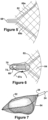
- FIG 7 is a perspective view of a distal portion of the device illustrated in Figure 4 , showing a food bolus captured within the net. In this position, the loop retains an expanded configuration with an object 80 retained within the pouch section 58. The surgeon or operator may further close the loop to secure or hold the food bolus.
- the endoscope now may be removed from the patient with risk of loss of the food bolus greatly reduced as compared to prior art devices.
Description
- The present invention relates to a retrieval device and to an endoscopic retrieval device for retrieving objects from within a human subject.
- Endoscopic retrieval or removal devices are known in the art and are conventionally used to recover objects from inside a human subject. Such objects may include severed human tissue, foreign objects, or food bolus. Some typical devices include forceps or clasps to grab objects.
- For example,
US 2003/004538A1 discloses an endoscopic surgical device for retrieving severed tissue or foreign bodies from within a subject is disclosed. The device comprises a support unit and a tissue retrieving net system. The net system is carried by the support unit and may be inserted into the subject through an orifice or small incision and operated to retrieve tissue that has been severed by a conventional method. The net system comprises a net, a net actuator, a net deployment and retrieval assembly for transmitting motion between the net and its actuator. The net system further comprises at least one net connector disposed such that only one connector is within an articulation zone, defined by locations of severe bending of the device during operation. -
US 2005/267489A1 discloses an endoscopic surgical device for retrieving objects, such as for example, severed human tissue, foreign objects or impacted food bolus, from within a subject is disclosed. The device includes a body and handle movable relative to the body, a tubular member fixed to the body, a link having a first end fixed to the handle and a second end remote from the body, and a net including a loop and a net element. The loop is expandable and collapsible by action of the handle relative to the body. The loop retains an expanded configuration when deployed to allow for the capture certain objects that were otherwise difficult to capture because of positioning, location, or object characteristics. The loop may be constructed of flat wire and form a polygon shape when deployed. Structure at the distal end of the loop may propel and retain the loop into an open position when in use in narrow organs such as the esophagus. -
US 5,906,621A discloses an endoscopic surgical device for severing tissue within a subject and for retrieving severed tissue from within the subject is disclosed. The device has a support unit, a tissue severing snare system, and a tissue retrieving net system. The snare and net systems are carried by the support unit and may be inserted into the subject through an orifice or small incision and individually operated to sever and retrieve tissue. The snare system includes a snare, a snare actuator, and a snare deployment and retrieval assembly for transmitting motion between the actuator and the snare. The net system includes a net, a net actuator, a net deployment and retrieval assembly for transmitting motion between the net and its actuator and a net controller for assuring the net is fully opened when deployed. -
US 5,098,441A discloses a lithotriptor with a catch basket which is formed by a plurality of outwardly curved catch strings made of wire material and which comprises a catch basket foot and a catch basket top to which the catch strings are fixed to each other, the catch strings being connected at the catch basket foot to a pull string which consists of a plurality of pull wires and which is guided in a casing, the pull string being slidably arranged in the casing by means of a pull mechanism for introducing and retracting the catch basket. For achieving a large load transmission the pull string is formed by a wire rope being stranded at least twice, the number of strands of which corresponds to at least the number of catch strings of the catch basket, wherein the catch strings are formed by deformed rope strands of the wire rope which continuously run from the wire rope up to the top of the catch basket. -
US 5,147,371A discloses a device for the in situ collection of surgically excised material, including whole gall bladder, gallstones, dissected gall bladder and other tissues, for removal from the body, particularly in laproscopic surgical procedures. The gallstone removal device is an elongated tube for insertion through a trocar sheath into the abdomen of a patient during gallbladder surgery. A single wire doubly traverses the tube, forming a full loop, preferably a double loop, at the end of the tubing inserted into the abdomen. A bag or pouch extends from the wire loop which is tethered to the tube, and the loop and attached pouch are caused to open and close by manipulation of the wire. -
US 5,190,542A discloses surgical instrument assembly for use in snare cauterization operations comprises a tubular sheath member, a metallic cauterization loop, and a metal wire operatively connected to the loop, the wire passing longitudinally through the sheath. An electrical supply is operatively connectable to the wire for feeding an electrical current to the loop via the wire, while a manually actuatable shifter is operatively connected to the wire for longitudinally sliding the wire along the sheath in alternately opposite directions. A flexible web member is connected to the loop to form a capture pocket, the loop defining a mouth opening of the pocket. During use of the snare cauterization instrument, the loop is at least partially expanded from a collapsed configuration and passed over a polyp to be removed, so that the web member substantially surrounds the selected polyp. The loop is then closed to engage the polyp around a base region thereof and an electrical current is subsequently conducted through the loop to burn through the polyp at the base region thereof. Severance of the polyp occurs upon a closure of the cauterization loop by its being withdrawn or retracted into the tubular sheath member. The severed polyp is automatically captured by the web member. - Certain devices of the above types may not be well-suited for retrieving rounded or blunt foreign objects such as coins, marbles and batteries because they are difficult to hold secure. Further, if a foreign object is dropped near the trachea during the removal process the results can be catastrophic for the patient.
- Other devices include a variety of net support and net operating structures.
- Many retrieval devices are used within an instrument channel of an endoscope during endoscopic medical procedures. These devices are generally expandable and collapsible relative to a tube inserted into the instrument channel. For example, a wire loop at the distal end of the device ma y expand and collapse relative to the tube by action of a handle at the proximal end of the device. Further, a net may be secured to the expandable and collapsible wire loop.
- The invention is disclosed by
independent claim 1, with further preferred embodiments disclosed in the dependent claims. Embodiments falling within the scope of the claims are illustrated infigures 15- 18 . - In an illustrated embodiment of the invention, a device for retrieving objects, such as for example, impacted food bolus, foreign objects, and severed human tissue, is disclosed. The device is for use within an instrument channel of an endoscope during endoscopic medical procedures.
- The device includes a body, a handle fixed to and movable relative to the body, an elongated tube fixed to the body, a link extending substantially through the tube and having a first end fixed to the handle and a second end remote from the body, and a net including a loop and a net element. The loop is expandable and collapsible by action of the handle relative to the body. The net is secured at distal and proximal locations relative to the handle. The device is more reliable, structurally simpler, and less costly to manufacture than prior devices.
- Further features and advantages of the invention will become apparent from the following detailed description made with reference to the accompanying drawings.
-
-
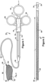
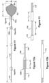
Figure 1 is a perspective view of a retrieval device constructed in accordance with an embodiment of the present disclosure; -
Figure 2 is a cross-sectional fragmentary view of the distal portion of the device illustrated inFigure 1 , showing a retrieval net in a stored position within a tube; -
Figure 3 is an alternative view ofFigure 2 , showing the retrieval net in a deployed position outside of the tube; -
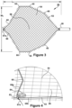
Figure 4 is an exploded perspective view of the designated circular section ofFigure 1 , showing detail of the net element and the distal end of the loop; -
Figure 5 is an exploded fragmentary view of the net of a retrieval device, showing an alternative distal end of the loop; -
Figure 6 is an exploded fragmentary view of the net of a retrieval device, showing yet another alternative distal end of the loop; -
Figure 7 is a perspective view of a distal portion of the device illustrated inFigure 4 , showing an exemplary food bolus captured within the retrieval net; -
Figures 8-10 are views of a portion of the device ofFigure 4 , showing the portion during a variety of assembly steps; -
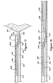
Figure 11 is a front elevation view of a distal portion of the device ofFigure 4 ; -
Figures 12a-12b and 13 are enlarged views of the designated circular sections ofFigure 11 , showing a variety of structural detail; -
Figure 14a is an enlarged sectional view of the device ofFigure 4 , showing a proximal net connection; -
Figure 14b is an enlarged sectional view of the device ofFigure 4 , showing another proximal net connection; -
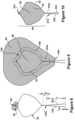
Figure 15 is a top view of a net element according to an embodiment of the invention; -
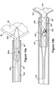
Figure 16 is a front elevation view of a distal portion of the device according to the embodiment of the claimed invention: -
Figure 17 is a cross-sectional fragmentary view of the distal portion of the device illustrated inFigure 16 , showing a retrieval net in a deployed position; and -
Figure 18 is a cross-sectional fragmentary view of the distal portion of the device illustrated inFigure 16 , showing the retrieval net in a stored position. - The Detailed Description merely describes preferred embodiments of the invention or of the present disclosure and is not intended to limit the scope of the invention or claims in any way.
- The scope of the invention is defined by the appended claims.
- Indeed, the invention as described by the claims is broader than and unlimited by the preferred embodiments, and the terms used have their full ordinary meaning.
- A device for retrieving an object from within a human subject is disclosed. In discussing the device, the terms distal and proximal are used with respect to the operator's hand. In other words, when the device is used within the instrument channel of an endoscope or similar device, the proximal and distal orientation are relative to the position of the surgeon or operator of the device. Further, it should be noted that the terms first connection, second connection, third connection, and the like do not imply a manufacturing order.
- It should also be noted that for the purposes of this application, the terms attach (attached), connect (connected), and link (linked) are not limited to direct attachment, connection, or linking but also include indirect attachment, connection, or linking with intermediate parts, components, or assemblies being located between the two parts being attached, connected, or linked to one another. In addition, the terms attach (attached), connect (connected), and link (linked) may include two parts integrally formed or unitarily constructed.
- For exemplary purposes only, the invention will be discussed in regard to a device designed for use within an endoscope for retrieving objects within relatively tight passages, such as for example, impacted food bolus from the esophagus. It should be apparent to others with ordinary skill in the art that the discussion and Figures included in this application are by way of example only, and that the invention can be utilized with endoscopic retrieval devices having a wide variety of structures, shapes, strengths, or purposes. One of many other exemplary uses for the invention is to remove polyps from the colon.
- As mentioned, devices using netting have been developed to capture rounded or blunt objects. In the use of devices having netting, and it is believed in the use of other devices, physicians have experienced difficulty in recovering certain objects, such as for example, impacted food bolus from the esophagus. A bolus is a mass of masticated or chewed food. In some cases, the bolus becomes impacted in the esophagus due to disease or other disorders and consequently does not pass into the stomach. It may be more difficult to position a net over an object of this type or the object may be heavier than the human tissue or foreign object for which a typical net device was originally designed. This problem is especially apparent when manipulating the device in relatively tight places within the body. As a result, netting support collapses and does not retain its shape in a deployed position when holding the captured object. Further, the netting may tear or net connections may fail causing reliability concerns.
- To solve these and other problems, the retrieval device of the invention is more reliable, structurally simpler, and less costly to manufacture than prior devices. For example, in some embodiments of the disclosure, the proximal portion of the net element is secured to the wire that forms the loop and leg portions of the retrieval net using a shorter tether or anchor than previous designs which anchor the net element at a more proximal location. In embodiments of the invention, no tether or anchor is used to secure the proximal portion of the net element and instead the net element is routed between welds, or other similar connections, connecting the leg portions of the wire together. Were no tether is used to secure the proximal portion of the net element, the chances of the net element breaking or tearing are reduced because the forces are distributed more evenly over a greater area instead of at an isolated point of contact.
- Further, in some further embodiments of the invention, the proximal portion of the net element at least partially surrounds the connection of the leg portions to the cable and/or the connection securing the leg portions together. As such, the proximal portion of the net element inhibits damage to the connections and the inside of the tubular member. The proximal portion of the net element also provides a damping effect on the cable movement toward the distal end of the tubular member when the handle is activated. This also provides more control over the deployment of the net and cable and controls the portion of the device that exits the opening of the tubular member when the retrieval net is in the deployed position. The proximal portion of the net element also helps to center the leg portions of the wire and the cable within the tubular member.
- The retrieval net generally collapses and expands relative to a tube inserted through the instrument channel of the endoscope. In the collapsed position, the retrieval net is small enough in diameter to fit inside at least the distal end of a lumen of the tubing. Further, any connection securing the net element to the loop should be small enough to fit within the lumen and allow the retrieval net to collapse and expand repeatedly. The connection should also be able to hold the net element in place relative to the loop during the expansion and collapse of the retrieval net. Further, the loop is generally connected to a motion transmitting link. The motion transmitting link allows the loop to be manipulated by a handle at the proximal end of the device. As such, any connection or connections securing the loop to the motion transmitting link must also be small enough to fit within the lumen and allow the retrieval net to collapse and expand repeatedly. If either of these connections is too large, the connection may drag or catch on the inside wall of the lumen. The friction between the connection and the inside wall of the lumen may prohibit essentially a 1:1 ratio between the movement of the handle and the movement of the distal end of the loop or retrieval net.
- The net element is generally supported by the loop by threading, or weaving, the flat wire through the holes in the net element. However, the net element may be supported by the loop by any suitable method known in the art. For example, the net element may wrap around the loop, like a sleeve, or be tied to the loop. Further, the net element may be secured to the wire by tethers, anchors, adhesives, or the like such that the net element is held in place relative to the loop during the expansion and collapse of the retrieval net. For example, tethers or anchors may be used to secure the net element to the distal end and the proximal end of the loop. In an embodiment of the disclosure, the proximal portion of the net element is attached adjacent a connection securing the two leg portions together, by a tether or anchor, such as for example, a string tie. The proximal portion of the net element may be attached using a tether or anchor to the proximal side of the connection securing the two leg portion together. The proximal portion of the net element may be attached using a tether or anchor to a 360 degree curved portion of at least one leg portion. The distal portion of the net element may also be attached using a tether or anchor to a 360 degree curved portion of the loop portion. In an embodiment of the invention, the proximal portion of the net element may be secured to the leg portions by routing the net element through connections securing the two leg portions together. The size and smooth or curved contour of these connections reduce the drag or friction on the inside wall of the lumen, permitting essentially a 1:1 ratio between the movement of the handle and the movement of the distal end of the loop or retrieval net.
- Referring now to the drawings,
Figure 1 is a perspective view of aretrieval device 10 constructed in accordance with an embodiment of the disclosure not falling within the scope of the claimed invention. Thedevice 10 includes a support base orelongated body 14. Thebody 14 includes aring 16 at a proximal end. Thedevice 10 also includes ahandle 18 having tworings 20. Thehandle 18 is mounted over an interior section 15 of thebody 14 and is movable relative to the body in the direction A1 as illustrated, or in an opposing direction. For example, an operator may place a finger in each of therings 20 and thumb of the same hand in thebody ring 16. By moving the two fingers in the direction A1, an operator can move thehandle 18 relative to thebody 14. In contrast, thehandle 18 can be slid in a direction opposite A1 by pulling one's fingers towards one's thumb. - The
device 10 includes an elongated introducer member ortubular member 24 having afirst end 26 fixed to thebody 14 and asecond end 28 remote from the body. Thetubular member 24 and thebody 14 are a fixed support assembly for the moving parts of thedevice 10. Thetubular member 24 may be any suitable, small-diameter tube formed of a non-reactive low-friction flexible material, such as for example, polytetraflourethylene. Thetubular member 24 defines a lumen with anopening 30 at the tubular membersecond end 28, as best seen inFigure 2 which shows a cross-sectional view of a distal portion of thedevice 10. - A
motion transmitting link 34 is connected to thehandle 18. The link can be a solid cable, a hollow tube, or any suitable elongated object or combination of objects for transferring axial motion from thehandle 18 to other parts of the device. Thelink 34 has afirst end 36 fixed to thehandle 18 and a second end remote from thebody 14. As shown in the drawings, the link extends substantially through thetubular member 24 lumen. The link may be constructed of any suitable rigid material. The link may be one piece or formed from a series of pieces and connections, such as for example, hypodermic tubes, swage connections, and cables. - Still referring to
Figure 1 , the device also includes aretrieval net 50. Theretrieval net 50 is used by the operator to capture and retrieve objects from within a human subject. Theretrieval net 50 includes aloop 52, or loop portion, and anet element 54 secured to the loop. Thenet element 54 is supported by theloop 52 by threading, or weaving, the loop through holes in the net element. However, thenet element 54 may be supported by theloop 52 by any suitable method known in the art. Further, it should be apparent to others with ordinary skill in the art that a variety of net shapes and sizes can be utilized in the practice of this disclosure. - As shown in
Figures 3 and 4 , a tether oranchor 57a disposed at the distal portion of thenet element 54 anchors the net element to theloop 52 at adistal end 53 of the loop. Other distal tether or anchor designs and distal net anchoring methods can be utilized in the practice of this disclosure. - As discussed, the
retrieval net 50 is designed for movement between two positions.Figures 1 and3 show theretrieval net 50 in a deployed position. In this position, theretrieval net 50 has a length L1 and a width W1.Figure 2 is a cross-sectional view of a distal portion of thedevice 10, showing theretrieval net 50 in a stored position within thetube 24. In this position, theretrieval net 50 has a length L2 which is considerably longer than L1. As shown inFigure 2 , theretrieval net 50 is disposed within thetube 24 for deployment and retrieval through the tubularmember lumen opening 30. By movement of thehandle 18 relative to thebody 14, theretrieval net 50 is movable between either the deployed or stored positions. - Referring again to
Figure 3 , theretrieval net 50 is illustrated in a deployed position and fully expanded outside of thetube 24second end 28. Thenet element 54 may be constructed of any suitable light weight material, such as for example,nylon mesh string 56, as best seen inFigure 4 . Thenet element 54 has a centrally located object receivingpouch section 58. To be discussed further in greater detail, captured objects rest within this section as shown inFigure 7 . - As discussed, the
retrieval net 50 shown inFigure 3 includes aloop portion 52 formed by a wire. Theloop 52 acts as a support for thenet element 54 when the retrieval net is deployed. Theloop 52 is resiliently movable between a collapsed position shown inFigure 2 to an expanded position shown inFigure 3 by operator action of thehandle 18 relative to thebody 14. Adistal end 53 of theloop 52 includes structure to resist collapse of the loop during use. - Referring now to
Figure 4 , an exploded perspective view of the designated circular section ofFigure 1 is shown. In the embodiment shown, theloop 52 is formed by a flat wire constructed of a resilient material, such as for example, 304 stainless steel. Theloop 52 may be constructed from a material having a tensile strength greater than 2.068 GPa (300.000 psi). - Again, it should be apparent to others with ordinary skill in the art that the present invention can be utilized with a
loop 52 constructed from a wide variety of materials. - The
device 10 as illustrated inFigures 3 and 4 includes several features that promote expansion and prohibit collapse when an object is held within thenet element 54 or the device is used in a relatively tight passage of the body. Theloop 52 includes several collapse-resistant bends 60. The location of thebends 60 act as memory points and are retained by theloop 52 through multiple deployments. These bends 60 are constructed such that theloop 52 forms a polygon shape when deployed. As shown, theloop 52 forms a general hexagon shape. It is believed that a polygon shape is more resilient and less likely to collapse when an object is held within the net or when retrieving an object within a narrow passage. It should be understood by those with ordinary skill in the art that the polygon shape shown inFigure 3 is for exemplary purposes only, and other polygon or non-polygon shapes can be used in the practice of the disclosure, such as for example oval or round shapes. - As shown in
Figure 4 , theloop 52 further includes a 360 degreecurved portion 64 disposed at adistal end 53 of the loop. Thiscurved portion 64 acts as a spring tip to further prohibit collapse when an object is held within theretrieval net 50. Thisspring tip 64 also acts to promotepolygon segments anchor 57a anchors thenet element 54 to thecurved portion 64 of theloop 52. - Several other embodiments include alternative shapes and structures of the distal end of the loop.
Figure 5 shows the distal end of the support wire in an alternative shape. Theloop 52 is bent to form a protrudingtip 68. It is believed that this shape promotespolygon segments - Referring to
Figure 6 , an exploded fragmentary view of other alternative structure of the distal end of theloop 52 is shown. As in the embodiment shown inFigure 5 , the distal end of theloop 52 is bent into a protrudingtip 68. Over thespring tip 68, atip cap member 70 is press fit or connected by another suitable technique. Thetip 70 may be constructed of plastic or any other suitable material. Thetip 70 includes anaperture 72 therethrough as a distal end. As shown, the tether oranchor 57a is placed through the aperture and tied off to secure thenet element 54 to theloop 52. To be discussed in greater detail, in one embodiment, a corresponding tether oranchor 57b can be used to secure thenet element 54 on the proximal side of theretrieval net 50. The tether oranchor 57b is illustrated inFigures 14a-14b as a tie-off. It should be understood by those with ordinary skill in the art that the illustrated tethers oranchors - Referring now to
Figures 8-10 , a portion of the device ofFigure 4 is shown during a variety of assembly steps. Theloop 52 of the wire is shown inFigure 8 in a polygon form prior to assembly within thetube 24. The wire extends back toward the proximal end of thedevice 10 and forms two adjacent, or leg,portions leg portions connection 104a, such as for example, with a weld or by crimping or twisting the portions together, having an axial length Lw of sufficient size to secure the portions together. As shown, theleg portions weld 104a. Theleg portions weld 104a a length L3. The extension lengths of the twoleg portions leg portions - The
net element 54 is shown inFigures 8-10 in various stages of assembly. InFigure 8 , thenet element 54 is shown as it is just beginning to be woven around theflat wire loop 52. For purposes of perspective only, thenet element 54 is shown in various positions inFigure 9 . With thenet element 54 in a first position, the net element has anouter edge 106. In this first position, thenet element 54 is shown to have theouter edge 106 cooperatively shaped with theloop 52. It should be apparent to others with ordinary skill in the art that a variety of net shapes and sizes can be utilized in the practice of this invention. Theouter edge 106 illustrates the size of thenet element 54 in relation to theloop 52 prior to the net element being woven on the loop. - In a second position, the outer edge of the
net element 54 now becomes line orouter edge 108. The second position showsnet element 54 after it is woven on theloop 52. As can be seen, after thenet element 54 is woven on theloop 52, theouter edge 106 of thenet element 54 is now closer in position to theloop 52. This change in position creates the receivingpouch 58. As shown inFigure 9 , thenet element 54 in the second position or woven position includes an outerperipheral portion 109 that extends beyond theloop 52. As shown inFigure 10 , thisexcess portion 109 can be trimmed or otherwise removed prior to final assembly. - Two tethers or anchors are shown anchoring the
net element 54 to theloop 52 inFigure 10 . A first distal tether oranchor 57a is shown, as previously described in regard toFigures 3 and 4 . A second proximal tether oranchor 57b is shown and extends from thenet element 54 to the proximal side ofconnection 104a securing theleg portions anchor 57b is shown in more detail inFigures 14a and 14b . -
Figure 11 is a front elevation view of the device shown after subsequent assembly steps have been completed. Asecond connection 104b proximal to thefirst connection 104a is shown. As shown, thesecond connection 104b is a weld. Thesecond connection 104b joins theleg portions cable 110. As best shown inFigure 12a , theleg portions Figure 8 , theleg portions proximal connection 104b may be the same or different than the length of thedistal connection 104a. Theconnection 104b is of adequate strength to maintain correlating axial movement between thecable 110 and theleg portions Figure 12b , a section ofheat shrink material 112 is shown over theconnection 104b to inhibit damage to the tubular member. - Referring now to
Figure 13 , the proximal end of thecable 110 is anchored axially in relation to the handle by a length ofhypodermic tube 114. InFigure 13 , thecable 110 is shown secured to thetube 114 by aswage connection 116 having a length Ls. Thetube 114 extends distally beyond theswage connection 116 of length L5. Theswage connection 116 is of adequate strength to maintain correlating axial movement between thetube 114 and thecable 110. As shown inFigure 11 , the overall length of the motion transmitting link, which includes thetube 114 and thecable 110, is L4. -
Figure 14a is an enlarged view of thedistal portion 28 of thetube 24. As shown, the tether oranchor 57b anchors the proximal portion of thenet element 54 and extends from the net element to the proximal side of theweld connection 104a. As shown, no internal connectors are used in this design to close theloop 52 or secure theloop 52 to thecable 110. -
Figure 14b is another enlarged view of thedistal portion 28 of thetube 24. As shown, the ends of theleg portions cable 110. However, theleg portions Figure 14b , the tether oranchor 57b anchors the proximal, or tail, portion of thenet element 54 to a 360curved portion 192 ofleg portion 102 of the wire. It should be apparent to others with ordinary skill in the art that the curved portion may be included on either or both leg portions of the wire. - In the exemplary device shown in
Figures 1-14b , thetube 114,cable 110, and connections thereof axially connect to form the transmittinglink 34. However, other combinations of elements are possible. - A
net element 254 is shown inFigure 15 according to an embodiment of the invention. As shown, thenet element 254 has anouter edge 206 cooperatively shaped with theloop portion 252 of thedevice 200 shown inFigure 16 . It should be apparent to others with ordinary skill in the art that a variety of net shapes and sizes can be utilized in the practice of this invention. Theedge 206 is illustrated as the size of thenet element 254 in relation to theloop 252 prior to the net element being woven on the loop. Further, as shown, the proximal portion of thenet element 254 comprises atail portion 290. As will be discussed, thetail portion 290 is used to secure thenet element 254 to the wire. -
Figures 16-18 show adevice 200 according to an embodiment of the invention as claimed. - As shown in
Figure 16 , thedevice 200 includes aretrieval net 250. Theretrieval net 250 includes a wire forming aloop portion 252 and twoadjacent leg portions net element 254 secured to the loop portion. Thenet element 254 is supported by theloop portion 252 by threading, or weaving, the wire through holes in the net element. As shown inFigure 16 , a tether oranchor 257a disposed at the distal portion of thenet element 254 anchors the net element to theloop portion 252 at a distal end of the loop portion. - The
retrieval net 250 ofdevice 200 is designed for movement between two positions.Figure 16 shows theretrieval net 250 in a deployed position.Figures 17 and 18 are cross-sectional views of a distal portion of thedevice 200, showing theloop portion 252 of the retrieval net in a deployed position (Figure 17 ) and stored position within the tube 224 (Figure 18 ). As shown inFigure 18 , the retrieval net is disposed within thetube 224 for deployment and retrieval through the tubular member lumen opening. By movement of thehandle 218 relative to thebody 214, theretrieval net 250 is movable between either the deployed or stored positions. - Referring again to
Figures 16 and17 , theretrieval net 250 is illustrated in a deployed position and fully expanded outside of thetube 224second end 228. Thenet element 254 may be constructed of any suitable light weight material, such as for example, nylon mesh string. Thenet element 254 has a centrally located object receivingpouch section 258. Further, as shown, the proximal portion of thenet element 254 includes atail portion 290. - As shown in
Figures 16-18 , the wire extends back toward the proximal end of thedevice 200 and forms twoadjacent leg portions leg portions connections leg portions leg portions - As shown in
Figures 16-18 , thetail portion 290 of thenet element 254 is routed between theconnections tail portion 290 of thenet element 254 is secured, or pinched, within theopening 292 defined by theconnections leg portions net element 254 between theconnections - Further, as shown in
Figures 17-18 , thetail portion 290 of thenet element 254 at least partially surrounds theconnection 204c of theleg portions cable 210. Thetail portion 290 of thenet element 254 provides a damping effect on thecable 210 movement toward thedistal end 228 of thetube 224 when thehandle 218 is activated. This also provides more control over the deployment of the net andcable 210 and controls the portion of the device that exits the opening of thetubular member 224 when the retrieval net is in the deployed position. The mesh of thetail portion 290 of thenet element 254 also helps to center theleg portions cable 210 within thetubular member 224. The mesh of thetail portion 290 of thenet element 254 also inhibits damage to theconnections tubular member 224. - In an exemplary operation using the device, the patient is intubated with an endoscope. The
device 10 is inserted through an instrument channel of the endoscope, either before or after intubation. The device is inserted with the retrieval net in a stored position. The surgeon or operator utilizing the optical features of the endoscope will identify the object for removal. After identification of the object, the surgeon or operator will move the handle with respect to the base to deploy the retrieval net into the deployed position. The surgeon or operator will manipulate the object into the receiving pouch by one of a variety of techniques, including the use of additional endoscopic tools. For example, the surgeon or operator may manipulate the snare over the top of the object and enclose the net, or manipulate the snare under the object and enclose the net. Further, the surgeon or operator may use the net as a scoop, relying on the lateral stability of the device. Once the object is within the pouch, the surgeon or operator may manipulate the handle with respect to the body to slightly close the net around the object.Figure 7 is a perspective view of a distal portion of the device illustrated inFigure 4 , showing a food bolus captured within the net. In this position, the loop retains an expanded configuration with an object 80 retained within thepouch section 58. The surgeon or operator may further close the loop to secure or hold the food bolus. The endoscope now may be removed from the patient with risk of loss of the food bolus greatly reduced as compared to prior art devices. - While several embodiments of the invention has been illustrated and described in considerable detail, the present invention is not to be considered limited to the precise construction disclosed. Various adaptations, modifications and uses of the invention may occur to those skilled in the arts to which the invention relates. It is the intention to cover all such adaptations and modifications falling within the scope of the claims filed herewith.
Claims (13)
- An endoscopic device for retrieving an object from within a human body, the device comprising:a support assembly comprising a base (214) and an elongated tubular member (224);a transmitting assembly comprising a handle (218) movable relative to the base, and a link having a first end fixed to the handle and a second end remote from the base, the link extending through at least a portion of the tubular member;a wire defining a loop portion (252) and two leg portions (201, 202), wherein each leg portion is disposed proximal from the loop portion and a proximal end of each leg portion is secured to the second end of the link by a first connection (204c), and the two leg portions are secured to each other by a second connection (204b) and a third connection (204a) at a location between the first connection and the loop portion, and wherein the third connection is between the second connection and the loop portion;a net element (254) having a distal portion secured to the loop portion (252) and a proximal portion (290), wherein the proximal portion of the net element is routed between an opening (292) defined by the second connection, the third connection, and the two leg portions; andwherein the loop portion is movable between an expanded position outside the tubular member and a collapsed position within the tubular member by action of the handle relative to the base.
- The device of claim 1, wherein the second connection is a weld securing the two leg portions to each other.
- The device of claim 1, wherein the third connection is a weld securing the two leg portions to each other.
- The device of claim 1, wherein the proximal portion of the net element is secured between the second connection, the third connection, and the two leg portions.
- The device of claim 1, wherein the proximal portion of the net element at least partially surrounds the first connection to inhibit damage to the inside of the tubular member.
- The device of claim 1, wherein bends in the loop portion promote expansion of the loop portion and prohibit collapse of the loop portion while retrieving the object from within the human body.
- The device of claim 1, wherein the wire further comprises a curved portion at a distal end of the loop portion forming a protruding tip that prohibits the collapse of the loop portion during use.
- The device of claim 7, wherein the protruding tip includes a tip cap having an aperture and a tether (257a) secures the distal portion of the net element to the aperture in the tip cap.
- The device of claim 1, wherein the wire further comprises a 360 degree curved portion at a distal end of the loop portion.
- The device of claim 9, wherein a tether secures the distal portion of the net element to the 360 degree curved portion of the wire at the distal end of the loop portion.
- The device of claim 1, wherein the transmitting link further comprises a tube attached to a cable (210) by a swage connection.
- The device of claim 11, wherein the cable is attached to the ends of the two leg portions of the wire by the first connection.
- The device of claim 1, wherein a piece of heat shrink material at least partially surrounds the first connection to inhibit damage to the inside of the tubular member.
Applications Claiming Priority (3)
| Application Number | Priority Date | Filing Date | Title |
|---|---|---|---|
| US94278807P | 2007-06-08 | 2007-06-08 | |
| EP08756773.1A EP2157915B1 (en) | 2007-06-08 | 2008-06-06 | Retrieval device |
| PCT/US2008/066161 WO2008154406A1 (en) | 2007-06-08 | 2008-06-06 | Retrieval device |
Related Parent Applications (1)
| Application Number | Title | Priority Date | Filing Date |
|---|---|---|---|
| EP08756773.1A Division EP2157915B1 (en) | 2007-06-08 | 2008-06-06 | Retrieval device |
Publications (2)
| Publication Number | Publication Date |
|---|---|
| EP3679874A1 EP3679874A1 (en) | 2020-07-15 |
| EP3679874B1 true EP3679874B1 (en) | 2024-04-10 |
Family
ID=40096501
Family Applications (2)
| Application Number | Title | Priority Date | Filing Date |
|---|---|---|---|
| EP08756773.1A Active EP2157915B1 (en) | 2007-06-08 | 2008-06-06 | Retrieval device |
| EP20152855.1A Active EP3679874B1 (en) | 2007-06-08 | 2008-06-06 | Retrieval device |
Family Applications Before (1)
| Application Number | Title | Priority Date | Filing Date |
|---|---|---|---|
| EP08756773.1A Active EP2157915B1 (en) | 2007-06-08 | 2008-06-06 | Retrieval device |
Country Status (4)
| Country | Link |
|---|---|
| US (1) | US8016838B2 (en) |
| EP (2) | EP2157915B1 (en) |
| JP (3) | JP5460582B2 (en) |
| WO (1) | WO2008154406A1 (en) |
Families Citing this family (17)
| Publication number | Priority date | Publication date | Assignee | Title |
|---|---|---|---|---|
| US6814739B2 (en) | 2001-05-18 | 2004-11-09 | U.S. Endoscopy Group, Inc. | Retrieval device |
| US8591521B2 (en) | 2007-06-08 | 2013-11-26 | United States Endoscopy Group, Inc. | Retrieval device |
| US9101342B2 (en) * | 2011-07-22 | 2015-08-11 | Rafic Saleh | Surgical retrieval apparatus and method with semi-rigidly extendable and collapsible basket |
| EP2934341A1 (en) | 2012-12-21 | 2015-10-28 | Cook Medical Technologies LLC | Surgical bag device and remote operating mechanism |
| US9364261B2 (en) * | 2013-05-14 | 2016-06-14 | Melvin G. Hector, JR. | Apparatus and method for removing a foreign object from a rectal cavity |
| US9572591B2 (en) | 2013-09-03 | 2017-02-21 | United States Endoscopy Group, Inc. | Endoscopic snare device |
| JP6634440B2 (en) * | 2014-09-19 | 2020-01-22 | エンドチョイス インコーポレイテッドEndochoice, Inc. | Surgical retrieval device |
| CN107920824A (en) * | 2015-05-15 | 2018-04-17 | 维兰德.K.沙马 | The snare of variable flexibility |
| CN116373331A (en) * | 2015-10-23 | 2023-07-04 | 安多卓思公司 | Method of attaching a mesh to a coated loop member of a surgical snare device |
| US11141177B2 (en) | 2015-11-30 | 2021-10-12 | Piranha Medical Llc | Blockage clearing devices, systems, and methods |
| JP6941620B2 (en) | 2015-11-30 | 2021-09-29 | ピラーナ メディカル エルエルシーPiranha Medical, LLC | Blockage removal |
| DE102016106955A1 (en) | 2016-04-14 | 2017-10-19 | medwork GmbH | Fremdkörperbergeeinrichtung for an endoscopic device, and endoscopic device |
| DE102016226295A1 (en) | 2016-12-29 | 2018-07-05 | Epflex Feinwerktechnik Gmbh | Medical catch nets instrument |
| EP3565487B1 (en) * | 2017-01-09 | 2024-03-06 | United States Endoscopy Group, Inc. | Retrieval device |
| JP2020506014A (en) * | 2017-02-10 | 2020-02-27 | ユナイテッド ステイツ エンドスコピー グループ,インコーポレイテッド | Snare injection device |
| JP7372238B2 (en) * | 2017-07-12 | 2023-10-31 | エンド-セラピューティクス・インコーポレーテッド | Endoscope snare net |
| CA3083204A1 (en) | 2017-11-27 | 2019-05-31 | Rafic Saleh | Endoscopic snare |
Family Cites Families (21)
| Publication number | Priority date | Publication date | Assignee | Title |
|---|---|---|---|---|
| US460940A (en) * | 1891-10-13 | Surgical instrument | ||
| US2197921A (en) * | 1939-06-07 | 1940-04-23 | Coleman H Nelson | Landing net |
| US2626447A (en) * | 1949-08-08 | 1953-01-27 | Thomas G Hunt | Rope connection |
| ATE110553T1 (en) | 1989-04-05 | 1994-09-15 | Gip Medizin Technik Gmbh | LITHOTRIPTOR. |
| US5354303A (en) * | 1991-01-09 | 1994-10-11 | Endomedix Corporation | Devices for enclosing, manipulating, debulking and removing tissue through minimal incisions |
| US5147371A (en) | 1991-06-28 | 1992-09-15 | Washington Charles N | Apparatus for removing gallstones and tissue during surgery |
| US5192286A (en) * | 1991-07-26 | 1993-03-09 | Regents Of The University Of California | Method and device for retrieving materials from body lumens |
| US5190542A (en) | 1991-11-05 | 1993-03-02 | Nakao Naomi L | Surgical retrieval assembly and related method |
| US5643283A (en) * | 1992-01-03 | 1997-07-01 | Younker; Marlin E. | Surgical pouch |
| US5279539A (en) * | 1992-08-17 | 1994-01-18 | Ethicon, Inc. | Drawstring surgical pouch and method of use for preventing ovarian adhesions |
| WO1994018888A1 (en) * | 1993-02-19 | 1994-09-01 | Boston Scientific Corporation | Surgical extractor |
| US5480404A (en) * | 1993-06-16 | 1996-01-02 | Ethicon, Inc. | Surgical tissue retrieval instrument |
| JPH07101802A (en) * | 1993-10-01 | 1995-04-18 | Kohei Hasegawa | Accommodation of encleated organ |
| US5906621A (en) * | 1996-05-14 | 1999-05-25 | United States Endoscopy Group, Inc. | Endoscopic surgical device |
| JPH10174688A (en) * | 1996-12-18 | 1998-06-30 | Asahi Optical Co Ltd | Manufacture of treating implement for endoscope |
| KR20010042218A (en) * | 1998-03-27 | 2001-05-25 | 찰스 더블유 프란즈 | Minimally-invasive medical retrieval device |
| US5971995A (en) * | 1998-03-30 | 1999-10-26 | Ethicon, Inc. | Surgical pouch instrument |
| US6626915B2 (en) * | 1998-04-23 | 2003-09-30 | Scimed Life Systems, Inc. | Medical retrieval device with loop basket |
| US6814739B2 (en) * | 2001-05-18 | 2004-11-09 | U.S. Endoscopy Group, Inc. | Retrieval device |
| US8057484B2 (en) | 2004-05-25 | 2011-11-15 | U.S. Endoscopy Group, Inc. | Retrieval device |
| US7547310B2 (en) * | 2005-03-29 | 2009-06-16 | Tyco Healthcare Group Lp | Specimen retrieval apparatus |
-
2008
- 2008-06-06 EP EP08756773.1A patent/EP2157915B1/en active Active
- 2008-06-06 WO PCT/US2008/066161 patent/WO2008154406A1/en active Application Filing
- 2008-06-06 EP EP20152855.1A patent/EP3679874B1/en active Active
- 2008-06-06 JP JP2010511374A patent/JP5460582B2/en active Active
- 2008-06-09 US US12/135,473 patent/US8016838B2/en active Active
-
2014
- 2014-01-14 JP JP2014004359A patent/JP5961195B2/en active Active
-
2016
- 2016-03-16 JP JP2016052687A patent/JP6194381B2/en active Active
Also Published As
| Publication number | Publication date |
|---|---|
| JP5961195B2 (en) | 2016-08-02 |
| EP3679874A1 (en) | 2020-07-15 |
| US8016838B2 (en) | 2011-09-13 |
| EP2157915A4 (en) | 2015-03-25 |
| JP6194381B2 (en) | 2017-09-06 |
| WO2008154406A1 (en) | 2008-12-18 |
| JP2010528785A (en) | 2010-08-26 |
| US20080306336A1 (en) | 2008-12-11 |
| JP5460582B2 (en) | 2014-04-02 |
| JP2014121622A (en) | 2014-07-03 |
| JP2016144657A (en) | 2016-08-12 |
| EP2157915A1 (en) | 2010-03-03 |
| EP2157915B1 (en) | 2020-01-22 |
Similar Documents
| Publication | Publication Date | Title |
|---|---|---|
| EP3679874B1 (en) | Retrieval device | |
| US20220125449A1 (en) | Retrieval device | |
| JP4154660B2 (en) | Recovery device | |
| EP1765192B1 (en) | Retrieval device | |
| US7875038B2 (en) | Releasable basket and method of making thereof | |
| US20090209987A1 (en) | Snare with capture-area enhancement | |
| EP1182975B1 (en) | Method for making a retrieval assembly | |
| KR20190133719A (en) | Apparatus and method for tissue retraction | |
| KR20230058497A (en) | Grappling systems and methods for lumen apposition or wound defects |
Legal Events
| Date | Code | Title | Description |
|---|---|---|---|
| PUAI | Public reference made under article 153(3) epc to a published international application that has entered the european phase |
Free format text: ORIGINAL CODE: 0009012 |
|
| STAA | Information on the status of an ep patent application or granted ep patent |
Free format text: STATUS: THE APPLICATION HAS BEEN PUBLISHED |
|
| AC | Divisional application: reference to earlier application |
Ref document number: 2157915 Country of ref document: EP Kind code of ref document: P |
|
| AK | Designated contracting states |
Kind code of ref document: A1 Designated state(s): AT BE BG CH CY CZ DE DK EE ES FI FR GB GR HR HU IE IS IT LI LT LU LV MC MT NL NO PL PT RO SE SI SK TR |
|
| RIN1 | Information on inventor provided before grant (corrected) |
Inventor name: RANALLO, CYNTHIA ANN Inventor name: KAYE, CHRISTOPHER, J. Inventor name: USPENSKI, ALEXIS Inventor name: BOYCE, AARON |
|
| RIN1 | Information on inventor provided before grant (corrected) |
Inventor name: RANALLO, CYNTHIA ANN Inventor name: KAYE, CHRISTOPHER, J. Inventor name: BOYCE, AARON Inventor name: USPENSKI, ALEXIS |
|
| STAA | Information on the status of an ep patent application or granted ep patent |
Free format text: STATUS: REQUEST FOR EXAMINATION WAS MADE |
|
| 17P | Request for examination filed |
Effective date: 20210115 |
|
| RBV | Designated contracting states (corrected) |
Designated state(s): AT BE BG CH CY CZ DE DK EE ES FI FR GB GR HR HU IE IS IT LI LT LU LV MC MT NL NO PL PT RO SE SI SK TR |
|
| P01 | Opt-out of the competence of the unified patent court (upc) registered |
Effective date: 20230513 |
|
| GRAP | Despatch of communication of intention to grant a patent |
Free format text: ORIGINAL CODE: EPIDOSNIGR1 |
|
| RIC1 | Information provided on ipc code assigned before grant |
Ipc: A61B 17/22 20060101ALN20231128BHEP Ipc: A61B 17/00 20060101ALN20231128BHEP Ipc: A61B 17/221 20060101AFI20231128BHEP |
|
| STAA | Information on the status of an ep patent application or granted ep patent |
Free format text: STATUS: GRANT OF PATENT IS INTENDED |
|
| RIC1 | Information provided on ipc code assigned before grant |
Ipc: A61B 17/22 20060101ALN20231212BHEP Ipc: A61B 17/00 20060101ALN20231212BHEP Ipc: A61B 17/221 20060101AFI20231212BHEP |
|
| INTG | Intention to grant announced |
Effective date: 20240104 |
|
| GRAS | Grant fee paid |
Free format text: ORIGINAL CODE: EPIDOSNIGR3 |
|
| GRAA | (expected) grant |
Free format text: ORIGINAL CODE: 0009210 |
|
| STAA | Information on the status of an ep patent application or granted ep patent |
Free format text: STATUS: THE PATENT HAS BEEN GRANTED |
|
| AC | Divisional application: reference to earlier application |
Ref document number: 2157915 Country of ref document: EP Kind code of ref document: P |
|
| AK | Designated contracting states |
Kind code of ref document: B1 Designated state(s): AT BE BG CH CY CZ DE DK EE ES FI FR GB GR HR HU IE IS IT LI LT LU LV MC MT NL NO PL PT RO SE SI SK TR |
|
| REG | Reference to a national code |
Ref country code: GB Ref legal event code: FG4D |
|
| REG | Reference to a national code |
Ref country code: CH Ref legal event code: EP |