EP3679667B1 - Configuring optical networks using a joint configuration model - Google Patents
Configuring optical networks using a joint configuration model Download PDFInfo
- Publication number
- EP3679667B1 EP3679667B1 EP19741657.1A EP19741657A EP3679667B1 EP 3679667 B1 EP3679667 B1 EP 3679667B1 EP 19741657 A EP19741657 A EP 19741657A EP 3679667 B1 EP3679667 B1 EP 3679667B1
- Authority
- EP
- European Patent Office
- Prior art keywords
- node
- type
- optical path
- nodes
- request
- Prior art date
- Legal status (The legal status is an assumption and is not a legal conclusion. Google has not performed a legal analysis and makes no representation as to the accuracy of the status listed.)
- Active
Links
- 230000003287 optical effect Effects 0.000 title claims description 150
- 238000000034 method Methods 0.000 claims description 27
- 230000006870 function Effects 0.000 claims description 12
- 238000004891 communication Methods 0.000 claims description 11
- 230000005055 memory storage Effects 0.000 claims 2
- 238000010586 diagram Methods 0.000 description 18
- 206010042602 Supraventricular extrasystoles Diseases 0.000 description 16
- 230000015654 memory Effects 0.000 description 13
- 230000005012 migration Effects 0.000 description 8
- 238000013508 migration Methods 0.000 description 8
- 238000005516 engineering process Methods 0.000 description 5
- 238000012790 confirmation Methods 0.000 description 4
- 238000012545 processing Methods 0.000 description 4
- 230000008859 change Effects 0.000 description 3
- 230000002457 bidirectional effect Effects 0.000 description 2
- 230000007246 mechanism Effects 0.000 description 2
- 230000008569 process Effects 0.000 description 2
- 238000000926 separation method Methods 0.000 description 2
- 230000005540 biological transmission Effects 0.000 description 1
- 230000001413 cellular effect Effects 0.000 description 1
- 238000004590 computer program Methods 0.000 description 1
- 238000013499 data model Methods 0.000 description 1
- 238000013500 data storage Methods 0.000 description 1
- 230000001419 dependent effect Effects 0.000 description 1
- 238000007726 management method Methods 0.000 description 1
- 238000012986 modification Methods 0.000 description 1
- 230000004048 modification Effects 0.000 description 1
- 230000006855 networking Effects 0.000 description 1
- 230000008929 regeneration Effects 0.000 description 1
- 238000011069 regeneration method Methods 0.000 description 1
- 230000004044 response Effects 0.000 description 1
- 230000003595 spectral effect Effects 0.000 description 1
- 238000012546 transfer Methods 0.000 description 1
Images


Classifications
-
- H—ELECTRICITY
- H04—ELECTRIC COMMUNICATION TECHNIQUE
- H04L—TRANSMISSION OF DIGITAL INFORMATION, e.g. TELEGRAPHIC COMMUNICATION
- H04L45/00—Routing or path finding of packets in data switching networks
- H04L45/12—Shortest path evaluation
- H04L45/124—Shortest path evaluation using a combination of metrics
-
- H—ELECTRICITY
- H04—ELECTRIC COMMUNICATION TECHNIQUE
- H04L—TRANSMISSION OF DIGITAL INFORMATION, e.g. TELEGRAPHIC COMMUNICATION
- H04L45/00—Routing or path finding of packets in data switching networks
- H04L45/62—Wavelength based
-
- H—ELECTRICITY
- H04—ELECTRIC COMMUNICATION TECHNIQUE
- H04Q—SELECTING
- H04Q11/00—Selecting arrangements for multiplex systems
- H04Q11/0001—Selecting arrangements for multiplex systems using optical switching
- H04Q11/0062—Network aspects
-
- H—ELECTRICITY
- H04—ELECTRIC COMMUNICATION TECHNIQUE
- H04J—MULTIPLEX COMMUNICATION
- H04J14/00—Optical multiplex systems
- H04J14/02—Wavelength-division multiplex systems
- H04J14/0227—Operation, administration, maintenance or provisioning [OAMP] of WDM networks, e.g. media access, routing or wavelength allocation
- H04J14/0254—Optical medium access
- H04J14/0256—Optical medium access at the optical channel layer
- H04J14/0257—Wavelength assignment algorithms
-
- H—ELECTRICITY
- H04—ELECTRIC COMMUNICATION TECHNIQUE
- H04J—MULTIPLEX COMMUNICATION
- H04J14/00—Optical multiplex systems
- H04J14/02—Wavelength-division multiplex systems
- H04J14/0227—Operation, administration, maintenance or provisioning [OAMP] of WDM networks, e.g. media access, routing or wavelength allocation
- H04J14/0254—Optical medium access
- H04J14/0256—Optical medium access at the optical channel layer
- H04J14/026—Optical medium access at the optical channel layer using WDM channels of different transmission rates
-
- H—ELECTRICITY
- H04—ELECTRIC COMMUNICATION TECHNIQUE
- H04J—MULTIPLEX COMMUNICATION
- H04J14/00—Optical multiplex systems
- H04J14/02—Wavelength-division multiplex systems
- H04J14/0227—Operation, administration, maintenance or provisioning [OAMP] of WDM networks, e.g. media access, routing or wavelength allocation
- H04J14/0254—Optical medium access
- H04J14/0267—Optical signaling or routing
-
- H—ELECTRICITY
- H04—ELECTRIC COMMUNICATION TECHNIQUE
- H04J—MULTIPLEX COMMUNICATION
- H04J14/00—Optical multiplex systems
- H04J14/02—Wavelength-division multiplex systems
- H04J14/0227—Operation, administration, maintenance or provisioning [OAMP] of WDM networks, e.g. media access, routing or wavelength allocation
- H04J14/0254—Optical medium access
- H04J14/0272—Transmission of OAMP information
-
- H—ELECTRICITY
- H04—ELECTRIC COMMUNICATION TECHNIQUE
- H04L—TRANSMISSION OF DIGITAL INFORMATION, e.g. TELEGRAPHIC COMMUNICATION
- H04L47/00—Traffic control in data switching networks
- H04L47/10—Flow control; Congestion control
-
- H—ELECTRICITY
- H04—ELECTRIC COMMUNICATION TECHNIQUE
- H04L—TRANSMISSION OF DIGITAL INFORMATION, e.g. TELEGRAPHIC COMMUNICATION
- H04L69/00—Network arrangements, protocols or services independent of the application payload and not provided for in the other groups of this subclass
- H04L69/16—Implementation or adaptation of Internet protocol [IP], of transmission control protocol [TCP] or of user datagram protocol [UDP]
- H04L69/168—Implementation or adaptation of Internet protocol [IP], of transmission control protocol [TCP] or of user datagram protocol [UDP] specially adapted for link layer protocols, e.g. asynchronous transfer mode [ATM], synchronous optical network [SONET] or point-to-point protocol [PPP]
-
- H—ELECTRICITY
- H04—ELECTRIC COMMUNICATION TECHNIQUE
- H04Q—SELECTING
- H04Q11/00—Selecting arrangements for multiplex systems
- H04Q11/0001—Selecting arrangements for multiplex systems using optical switching
- H04Q11/0062—Network aspects
- H04Q2011/0079—Operation or maintenance aspects
Definitions
- the present disclosure is related to configuring optical networks, and in particular to using a joint configuration model to configure diverse optical networks to form an optical path.
- Optical networks may involve the use of different types of nodes, such as wavelength switched optical networks (WSON) nodes and newer, higher bandwidth flexible grid (Flexi-Grid) nodes.
- WSON wavelength switched optical networks
- Flexi-Grid newer, higher bandwidth flexible grid
- the different types of nodes utilize different configurations and methods of describing channel parameters, such as frequencies and channel separation frequencies.
- CHANNEGOWDA MAYUR ET AL: “Software-defined optical networks technology and infrastructure: Enabling software-defined optical network operations [invited] " discloses Software-defined networking (SDN) enables programmable SDN control and management functions at a number of layers, allowing applications to control network resources or information across different technology domains, e.g., Ethernet, wireless, and optical.
- SDN Software-defined networking
- the functions or algorithms described herein may be implemented in software in one embodiment.
- the software may consist of computer executable instructions stored on computer readable media or computer readable storage device such as one or more non-transitory memories or other type of hardware based storage devices, either local or networked.
- modules which may be software, hardware, firmware or any combination thereof. Multiple functions may be performed in one or more modules as desired, and the embodiments described are merely examples.
- the software may be executed on a digital signal processor, ASIC, microprocessor, or other type of processor operating on a computer system, such as a personal computer, server or other computer system, turning such computer system into a specifically programmed machine.
- Optical networks may involve the use of different types of nodes along an optical path between a source and destination, such as WSON nodes and newer, higher bandwidth Flexi-Grid nodes.
- Nodes in an optical network may be capable of one or more of switching optical signals and regeneration of optical signals.
- the optical path may be bidirectional or unidirectional.
- the different types of nodes utilize different configurations and methods of describing channel parameters, such as frequencies and channel separation frequencies.
- Optical network controllers configure the nodes using different configuration models for each type of node to establish one or more optical paths.
- a control plane mechanism used to configure the nodes for providing an optical path for communications has to change when an older node is replaced with a newer node. Changing the mechanism for each replaced node becomes time consuming and subject to error, adding expense to the migration.
- a provisioning network controller PNC
- WSON Wireless Fidelity
- Flexi-Grid nodes to configure an optical path.
- the PNC does not need to change the configuration model when WSON networks migrate to Flexi-Grid networks, allowing for easier migration.
- a multi-domain controller referred to as a multi-domain service coordinator (MDSC) may use one configuration interface to each homogenous or heterogeneous PNC, such as one or more PNCs that control domains having WSON nodes, PNCs that control domains having Flexi-Grid nodes, and PNCs that control domains having mixed nodes, such as one or more WSON nodes and Flexi-Grid nodes.
- the configuration model may be modified to support more types of nodes with similar advantages.
- FIG. 1 is a block diagram of an optical network 100 showing an optical path 110 extending between a source 115 and a destination 120.
- the optical path 110 traverses through a first node 125 and a second node 130, both of which are configured by a controller, PNC 135, to establish the optical path.
- the first and second nodes 125, 130 may be different.
- the first node 125 is a WSON node
- the second node is a newer, higher bandwidth Flexi-Grid node 130. Both such nodes have different data plane capabilities and are controlled differently in order to configure the single optical path 110.
- a WSON node may perform switching selectively based on a center wavelength of an optical signal and has a fixed 50Ghz slot width. Flexi-grid nodes perform switching based on a center wavelength but with variable size slot width.
- PNC 135 utilizes a joint configuration model 140 in order to control the nodes 125 and 130 via connections 145 and 150, respectively, and configure them for data plane based operations.
- Configuration model 140 may be used to configure first node 125 by specifying, for example, a selected frequency of 193.1 (THz) and a channel spacing of 50 (GHz).
- the configuration model 140 may be stored and accessed within PNC 135, or stored and accessed remote from PNC 135 in various embodiments.
- the second node 130 is a Flexi-Grid node, which has a higher bandwidth capability, both in terms of selected frequency, with a base frequency of 193.1 THz and a more granular channel spacing capability. Flexi-Grid nodes are able to fit four channels into a same frequency range as a WSON node.
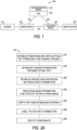
- FIG. 2A is a flowchart illustrating a method 270 for establishing an optical path in a network of different types of nodes.
- path frequency and channel spacing are specified for a WSON read and write optical path.
- the same path frequency and channel spacing are specified for a Flexi-Grid optical path using a different nomenclature that is compatible with Flexi-Grid nodes.
- source and destination are established, along with wavelength parameters.
- the established parameter referred to as the state of the path are then read at operation 283 from the nodes in the path.
- the read parameters are verified at operation 285 to ensure the path was properly established.
- the path is labeled with the parameters, and at operation 290, constraints of the path, if any, are identified.
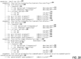
- the configuration model may be expressed as an Internet Engineering Task Force (IETF) YANG tree as shown in pseudocode in FIG. 2 at YANG model 200 describing operations for establishing an optical path (te:tunnel (traffic engineered tunnel)), referred to in the pseudocode as a module named ietf-te-L0 at 202.
- Operation 204 describes that language from an already established model compiled YANG model is being borrowed for use in YANG model 200 and begins configuration (config) of nodes in the path.
- Operation 206 is used to describe that the path to be established is a read/write (rw) te L0 slot, while line 208 indicates that the following operations are for WSON nodes, identifying the channel frequency at 210 as a 64 bit decimal format and channel spacing at 212 as a 64 bit decimal format.
- a te L0 slot is a traffic engineering slot with L0 being a container of YANG to describe Layer 0 Slot of the tunnel between nodes to be configured.
- Operation 214 is used to identify that following operations are for Flexi-Grid nodes and identify parameter N as a 32 bit integer at 216 and M as a 32 bit integer at 218.
- Operations 220 and 222 define the source client signal and destination client signal.
- Operation 224 describes the wavelength assignment for the path.
- Operation 226 causes a read of what was configured, the state of the path.
- Operations 228, 230, 232, 234, 236, 238, 240, 242, 244, and 246 have a similar format to the above configuration operations 206-224, and serve to read values from configured nodes to ensure configuration of WSON and Flexi-Grid nodes was performed properly.
- Operation 248 is used to label a switched path (lsp) corresponding to the optical path through multiple nodes in the optical network.
- Operation 250 indicates whether the path is bidirectional or unidirectional and is a Boolean value. Note that the while YANG model 200 uses specified numbers of bits or types of values, different numbers of bits or types of values may be used in other embodiments.
- Operations 252, 254, 256, 258, 260, 262, and 264 are similar to the above sets of operations and describe the selected channel frequency and spacing for the WSON and Flexi-Grid nodes.
- Operation 266 is used to identify constraints, such as shown at operation 268 wherein an rw wavelength assignment is identified.
- the assignment may be set via random assignment as show, or globally, which allows direct identification of the wavelength to allow tailoring for a specific instance of a path.
- FIGs. 3A and 3B are a commented representation of a container: L0-slot that illustrates the YANG model of FIG. 2 shown generally at 300.
- a grouping of tunnel properties is illustrated at 310 where configuration parameters relating to TE L0 Tunnel attributes are specified.
- WSON case 325 includes the configuration parameters relating to TE WSON Tunnel attribute flags, such as leaf (channel) selected frequency, type, units of THz, default channel frequency 193.1 THz, and leaf channel spacing which is 12.5 GHz for WSON nodes.
- Case 330 shows technology specifics of Flexi-Grid nodes, such as configuration parameters N and M.
- N is used to determine the Nominal Central Frequency.
- M is used to determine the slot width.
- a slot width is constrained to be M ⁇ SWG (slot width grid) (that is, M ⁇ 12.5 GHz), where M is an integer greater than or equal to 1. Note that even further different types of nodes may be similarly calculated once the frequency and channel spacing is specified for any one of the types of nodes in the format utilized for such type of node.
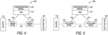
- FIG. 4 is a block diagram of an optical network 400 showing an optical path 410 extending between a source 115 and a destination 120. Note that reference numbers are used for like components in each of the optical network figures. Each of the optical network figures show only the nodes and controllers used for establishing an optical path. The optical networks may consist of many other nodes and optical connections that are not used for the illustrated optical path and are not shown for convenience of illustration.
- the optical path 410 traverses through two WSON nodes 125, both of which are configured by a controller, PNC 135, to establish the optical path. Both nodes have the same data plane capabilities.
- PNC 135 utilizes the joint configuration model 140 in order to control the nodes via connections 145 and configure them for data plane based operation.
- Configuration model 140 may be used to configure both nodes 125 by specifying, for example, a selected frequency of 193.1 (THz) and a channel spacing of 50 (GHz).
- FIG. 5 is a block diagram of an optical network 500 showing an optical path 510 extending between a source 115 and a destination 120.
- the optical path 510 traverses through a pair of nodes 130, both of which are configured by a controller, PNC 135, to establish the optical path.
- Nodes 130 are both Flexi-Grid nodes.
- PNC 135 utilizes a joint configuration model 140 in order to control the nodes via connections 150 and configure them for data plane based operation.
- the nodes 130 may have been upgraded or migrated from WSON nodes as shown in FIG. 4 .
- the use of a joint configuration model for multiple types of nodes allows such migration without having to modify the configuration model during the migration.
- FIG. 6A is a block diagram of an optical network 600 showing an optical path 610 extending between a source 115 and a destination 120.
- the optical path 610 traverses through multiple pairs of nodes 125 and 130, which are configured by a pair of controllers, both shown as PNC 135, to establish the optical path.
- Nodes 125 are both WSON nodes in a domain controlled by one PNC 135 while nodes 130 are both Flexi-Grid nodes in a domain controlled by another PNC 135.
- PNC 135 utilizes a joint configuration model 140 in order to control the nodes via connections 150 and configure them for data plane based operation as described above.
- a controller such as a multiple domain service coordinator (MDSC) 605 is used to control both PNCs 135 via one configuration interface as indicated by connections 615 and 620. Such control may be done without regard to the different types of nodes in the different domains.
- MDSC multiple domain service coordinator
- FIG. 6B is a flowchart illustrating a method 630 of controlling nodes via the connections 150 to configure them for data plane based operation.
- each PNC 135 will receive control information from MDSC 605, such as frequency and channel spacing information in a single format and convert such control information using the configuration model 140 as indicated at operation 640.
- the PNC 135 coupled to the WSON nodes 125 configures the WSON nodes 125 with the proper frequency and channel spacing.
- the PNC 135 coupled to the Flexi-Grid nodes 130 configures the Flexi-Grid nodes with the converted control information to operate at the same frequency and channel spacing.
- MDSC 605 also selects and coordinates the PNCs to establish the tunnel, i.e., the optical path 610.
- the nodes 130 may have been upgraded or migrated from WSON nodes.
- the use of a joint configuration model 140 for multiple types of nodes 125, 130 allows such migration without having to modify the configuration model during the migration. Migration of the entire optical network may occur over time, without having to upgrade the entire network at the same time and without having to change the joint configuration model during that time.
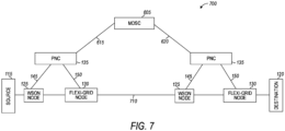
- FIG. 7 is a block diagram of an optical network 700 showing an optical path 710 extending between a source 115 and a destination 120.
- the optical path 710 traverses through multiple nodes 125 and 130 in different, mixed node domains.
- the nodes are all configured by a PNCs 135, to establish the optical path. Domains with mixed nodes, both WSON nodes and Flexi-Grid nodes are each controlled by a PNC 135.
- Method 635 may be executed by each PNC 135 to configure their respective WSON node and Flexi-Grid node.
- PNC 135 utilizes a joint configuration model 140 (not shown here) in order to control the nodes via connections 145 and 150 and configure them for data plane based operation as described above.
- An MDSC 605 is used to control both PNCs 135 via one configuration interface as indicated by connections 615 and 620. Such control may be done without regard to the different types of nodes in the different domains.
- Each PNC 135 will receive control information from MDSC 605, such as frequency and channel spacing information in a single format and convert such control information using the configuration model 140. MDSC 605 also selects and coordinates the PNCs to establish the tunnel, i.e., the optical path 610.
- FIG. 8 is a diagram showing configuration message flow 800 for configuring an optical path or tunnel in an optical network.
- Flow 800 establishes a LOTE-tunnel (Layer zero, traffic engineered-tunnel), at one or more WSON nodes 125 by one or more PNCs 135 in one embodiment, but other types of optical paths may be established in a similar manner.
- a first control request 810, POST/tunnels/tunnel/L0TE-tunnel is a communication sent from PNC 135 to WSON node 125 to establish tunnel or optical path.
- WSON node 125 processes the command and returns a confirmation 820 of HTTP 200: Tunnel, confirming that the tunnel has been established.
- POST is an HTTP (hyper text transfer protocol) message that tells the receiver to "configure" the optical path. In this case, the message informs the receiver to configure the optical path based on YANG model container called tunnels/tunnel/L0TE-tunnel.
- HTTP 200 is a status code indicating that the request has succeeded.
- a POST is a request in HTTP.
- FIG. 9 dis a diagram showing configuration message flow 900 for configuring an optical path or tunnel in an optical network.
- Flow 900 establishes a LOTE-tunnel at one or more Flexi-Grid nodes 130 by one or more PNCs 135 in one embodiment, but other types of optical paths may be established in a similar manner.
- a first control command 910, POST/tunnels/tunnel/L0TE-tunnel is sent from PNC 135 to Flexi-Grid node 130, which processes the command and returns a confirmation 920 of HTTP 200: Tunnel, confirming that the tunnel has been established.
- FIG. 10 is a diagram showing configuration message flow 1000 for configuring an optical path or tunnel in an optical network having a diverse mix of nodes, such as WSON nodes 125 and Flexi-Grid nodes 135.
- Flow 1000 establishes a LOTE-tunnel at one or more nodes 125, 130 by one or more PNCs 135 in one embodiment.
- An MDSC 605 is used to establish the optical path over multiple domains controlled by multiple PNCs 135.
- Two POST requests 1010 and 1020 are used for respective PNCs 135. Both PNCs send POST requests 810 and 910 to respective types of nodes and receive confirmations 820 and 920 as described with respect to FIGs. 8 and 9 .
- Each PNC 135 for the different domains forward the respective confirmations 1030 and 1040 back to the MDSC to establish the tunnel/optical path. While only two PNCs 135 and nodes 125, 130 are shown, it should be understood that there may be many more such PNCs and nodes involved in the path, and that such domains may each have mixed nodes or homogenous nodes - nodes of the same type.
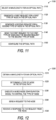
- FIG. 11 is a flowchart illustrating operations for execution by suitable computing resources, such as a PNC or a node controller in an optical network, to perform an example method 1100 of configuring an optical network having mixed nodes while using a single joint configuration model.
- Operation 1110 may be performed to select a wavelength for the optical path. The wavelength may be selected randomly or assigned by a multi-domain controller in different embodiments.
- Operation 1120 may be executed to generate a first request for a first type of node in the optical path.
- Operation 1130 may be executed to generate a second request for a second type of node in the optical path.
- the second type of node may have different data plane capabilities than the first type of node.
- the first and second requests may be generated as a function of the joint configuration model accommodating both types of nodes. Operation 1140 may be performed to send the first request to the first type of node and the second request to the second type of node to configure the optical path at operation 1150.
- first and second types of nodes have wavelength capabilities that are specified differently in their respective requests.
- the first and second requests may be generated and sent via a provisioning network controller node in communication with the first and second type nodes.
- the first and second requests may be generated and sent via a multi-domain service coordinator communicatively coupled to heterogeneous provisioning network controller nodes. Each controller node may be in communication with multiple first or second type nodes in the optical path.
- the first type of node may comprise a WSON node and the second type of node may comprise a Flexi-Grid node.
- the first request may specifies a path frequency and channel spacing of the optical path and the second request specifies the frequency and channel spacing as a function of a multiple of slot widths of the Flexi-Grid node to match the channel spacing specified for the WSON node.
- the first request for the WSON directly specifies the path frequency f p and channel spacing f cs
- the joint configuration model may be in the form of a compiled YANG tree.
- FIG. 12 is a flowchart illustrating operations for execution by suitable computing resources, such as a PNC or node controller in an optical network, to perform an example method 1200 of configuring an optical network having mixed nodes while using a single joint configuration model.
- suitable computing resources such as a PNC or node controller in an optical network
- a channel wavelength for an optical path may be obtained. Obtaining such a wavelength may be performed by receiving the wavelength from another controller or generating it randomly responsive to a request for an optical path.
- Operation 1220 determines a type of node in the optical path.
- Operation 1230 involves executing a mixed node configuration model to determine how to control the type of node.
- the mixed node configuration model is used for configuring multiple different types of nodes which each have different control plane capabilities and may differ in the way channel parameters are specified to control the type of node coupled to the controller.
- the configuration plane determines, based on the node type, how to specify the channel parameters.
- a configuration request is sent to the node in accordance with the configuration model, and at operation 1250, a response may be received from the node, confirming the request.
- the method 1200 may be used multiple times by one or more controllers which may be controlling different domains of nodes in a large optical network.
- the use of a joint configuration file enables configuration of mixed nodes throughout the domains without having to ensure each controller has a different or multiple different configuration files for each of the types of nodes in their respective domains.
- FIG. 13 is a block diagram illustrating circuitry/programming resources for using a joint configuration model for configuring mixed nodes in an optical network to establish a tunnel/optical path through the network regardless of the use of different types of nodes in the resulting path and for performing methods according to example embodiments. All components need not be used in various embodiments.
- One example computing device in the form of a computer 1300 may include a processing unit 1302, memory 1303, removable storage 1310, and non-removable storage 1312.
- the example computing device is illustrated and described as computer 1300, the computing device may be in different forms in different embodiments.
- the computing device may instead be a smartphone, a tablet, smartwatch, controller, or other computing device including the same or similar elements as illustrated and described with regard to FIG. 13 .
- Devices, such as smartphones, tablets, and smartwatches are generally collectively referred to as mobile devices or user equipment.
- the various data storage elements are illustrated as part of the computer 1300, the storage may also or alternatively include cloud-based storage accessible via a network, such as the Internet or server based storage.
- Memory 1303 may include volatile memory 1314 and non-volatile memory 1308.
- Computer 1300 may include - or have access to a computing environment that includes - a variety of computer-readable media, such as volatile memory 1314 and non-volatile memory 1308, removable storage 1310 and non-removable storage 1312.
- Computer storage includes random access memory (RAM), read only memory (ROM), erasable programmable read-only memory (EPROM) or electrically erasable programmable read-only memory (EEPROM), flash memory or other memory technologies, compact disc read-only memory (CD ROM), Digital Versatile Disks (DVD) or other optical disk storage, magnetic cassettes, magnetic tape, magnetic disk storage or other magnetic storage devices, or any other medium capable of storing computer-readable instructions.
- Computer 1300 may include or have access to a computing environment that includes input interface 1306, output interface 1304, and a communication interface 1316.
- Output interface 1304 may include a display device, such as a touchscreen, that also may serve as an input device.
- the input interface 1306 may include one or more of a touchscreen, touchpad, mouse, keyboard, camera, one or more device-specific buttons, one or more sensors integrated within or coupled via wired or wireless data connections to the computer 1300, and other input devices.
- the computer may operate in a networked environment using a communication connection to connect to one or more remote computers, such as database servers.
- the remote computer may include a personal computer (PC), server, router, network PC, a peer device or other common DFD network switch, or the like.
- a computer device capable of configuring an optical path includes a selecting means for selecting a wavelength for the optical path and generating means for generating a first request for a first type of node in the optical path and a second request for a second type of node in the optical path, the second type of node having different data plane capabilities than the first type of node, wherein the first and second requests are generated as a function of a joint configuration model accommodating both types of nodes.
- the computer device further includes sending means for sending the first request from the one or more processors to the first type of node and the second request to the second type of node to configure the optical path.
- the communication connection may include a Local Area Network (LAN), a Wide Area Network (WAN), cellular, WiFi, Bluetooth, optical, or other networks.
- LAN Local Area Network
- WAN Wide Area Network
- cellular Wireless Fidelity
- WiFi Wireless Fidelity
- Bluetooth Wireless Fidelity
- optical optical
- system bus 1320 the various components of computer 1300 are connected with a system bus 1320.
- Computer-readable instructions stored on a computer-readable medium are executable by the processing unit 1302 of the computer 1300, such as a program 1318.
- the program 1318 in some examples comprises software that, when executed by the processing unit 1302, performs node configuration operations according to any of the examples included herein.
- a hard drive, CD-ROM, and RAM are some examples of articles including a non-transitory computer-readable medium such as a storage device.
- the terms computer-readable medium and storage device do not include carrier waves to the extent carrier waves are deemed too transitory.
- Storage can also include networked storage, such as a storage area network (SAN).
- Computer program 1318 may be used to cause processing unit 1302 to perform one or more methods or algorithms described herein.
Landscapes
- Engineering & Computer Science (AREA)
- Computer Networks & Wireless Communication (AREA)
- Signal Processing (AREA)
- Computer Security & Cryptography (AREA)
- Data Exchanges In Wide-Area Networks (AREA)
- Optical Communication System (AREA)
Description
- The present disclosure is related to configuring optical networks, and in particular to using a joint configuration model to configure diverse optical networks to form an optical path.
- Optical networks may involve the use of different types of nodes, such as wavelength switched optical networks (WSON) nodes and newer, higher bandwidth flexible grid (Flexi-Grid) nodes. The different types of nodes utilize different configurations and methods of describing channel parameters, such as frequencies and channel separation frequencies.
CHANNEGOWDA MAYUR ET AL: "Software-defined optical networks technology and infrastructure: Enabling software-defined optical network operations [invited]" discloses Software-defined networking (SDN) enables programmable SDN control and management functions at a number of layers, allowing applications to control network resources or information across different technology domains, e.g., Ethernet, wireless, and optical. LOPEZ DE VERGARA UNIVERSIDAD AUTONOMA DE MADRID V LOPEZ O GONZALEZ DEDIOS TELEFONICA l+D/GCTO D KING OLD DOG CONSULTING Z ALI J E: "A YANG data model for WSON and FlexiGrid Optical Networks; draft-vergara-flexigrid-yang-00.txt" defines a YANG model for managing dynamic Optical networks, including Wavelength Switched Optical Networks (WSON) and Flexi-Grid DWDM Networks. The model described in this document is composed of two submodels: one to define an optical traffic engineering database, and other one to describe the optical paths or media channels.
"Spectral grids for WDM applications: DWDM frequency grid; G.694.1 (02/12)" provides the definition of a frequency grid to support dense wavelength division multiplexing (DWDM) applications. - The invention is defined by the independent claims. Further embodiments of the invention are defined by the dependent claims. Although the invention is only defined by the claims, the below embodiments, examples and aspects are present for aiding in understanding the background and advantages of the invention.
-
-
FIG. 1 is a block diagram of an optical network showing an optical path extending between a source and a destination according to an example embodiment. -
FIG. 2A is a flowchart illustrating a method for establishing an optical path in a network of different types of nodes according to an example embodiment. -
FIG. 2B is pseudocode for a joint YANG (Yet Another Next Generation) model for configuring controller nodes in an optical network according to an example embodiment. -
FIGs. 3A and3B are a commented representation of a container representing the YANG model ofFIG. 2 according to an example embodiment. -
FIG. 4 is a block diagram of an optical network showing an optical path extending between a source and a destination according to an example embodiment. -
FIG. 5 is a block diagram of an alternative optical network showing an optical path extending between a source and a destination according to an example embodiment. -
FIG. 6A is a block diagram of a further alternative optical network showing an optical path extending between a source and a destination according to an example embodiment. -
FIG. 6B is a flowchart illustrating a method to configure different type nodes for data plane based operation according to an example embodiment. -
FIG. 7 is a block diagram of an optical network showing yet a further alternative optical path extending between a source and a destination according to an example embodiment. -
FIG. 8 is a diagram showing configuration message flow for configuring an optical path or tunnel via a first type of control node in an optical network according to an example embodiment. -
FIG. 9 is a diagram showing configuration message flow for configuring an optical path or tunnel via a second type of control node in an optical network according to an example embodiment. -
FIG. 10 is a diagram showing configuration message flow for configuring an optical path or tunnel via a diverse set of control nodes in an optical network according to an example embodiment. -
FIG. 11 is a flowchart illustrating a computer implemented method of configuring an optical network according to an example embodiment. -
FIG. 12 is a flowchart illustrating operations for performing a method of configuring an optical network having mixed nodes while using a single joint configuration model. -
FIG. 13 is a block diagram illustrating circuitry for clients, servers, cloud based resources for implementing algorithms and performing methods according to example embodiments. - In the following description, reference is made to the accompanying drawings that form a part hereof, and in which is shown by way of illustration specific embodiments which may be practiced. These embodiments are described in sufficient detail to enable those skilled in the art to practice the invention, and it is to be understood that other embodiments may be utilized and that structural, logical and electrical changes may be made without departing from the scope of the present invention. The following description of example embodiments is, therefore, not to be taken in a limited sense, and the scope of the present invention is defined by the appended claims.
- The functions or algorithms described herein may be implemented in software in one embodiment. The software may consist of computer executable instructions stored on computer readable media or computer readable storage device such as one or more non-transitory memories or other type of hardware based storage devices, either local or networked. Further, such functions correspond to modules, which may be software, hardware, firmware or any combination thereof. Multiple functions may be performed in one or more modules as desired, and the embodiments described are merely examples. The software may be executed on a digital signal processor, ASIC, microprocessor, or other type of processor operating on a computer system, such as a personal computer, server or other computer system, turning such computer system into a specifically programmed machine.
- Optical networks may involve the use of different types of nodes along an optical path between a source and destination, such as WSON nodes and newer, higher bandwidth Flexi-Grid nodes. Nodes in an optical network may be capable of one or more of switching optical signals and regeneration of optical signals. The optical path may be bidirectional or unidirectional.
- The different types of nodes utilize different configurations and methods of describing channel parameters, such as frequencies and channel separation frequencies. Optical network controllers configure the nodes using different configuration models for each type of node to establish one or more optical paths.
- When optical networks are mixed with Fixed-Grid (WSON) and Flexible-Grid (Flexi-Grid) nodes, both types of nodes need to be supported to properly configure an optical path in the network.
- During migration of an optical network from older type nodes to newer nodes, a control plane mechanism used to configure the nodes for providing an optical path for communications has to change when an older node is replaced with a newer node. Changing the mechanism for each replaced node becomes time consuming and subject to error, adding expense to the migration.
- Various aspects of the inventive subject matter facilitate the use of a joint configuration model by a controller, referred to as a provisioning network controller (PNC) to control both WSON and Flexi-Grid nodes to configure an optical path. The PNC does not need to change the configuration model when WSON networks migrate to Flexi-Grid networks, allowing for easier migration.
- A multi-domain controller, referred to as a multi-domain service coordinator (MDSC) may use one configuration interface to each homogenous or heterogeneous PNC, such as one or more PNCs that control domains having WSON nodes, PNCs that control domains having Flexi-Grid nodes, and PNCs that control domains having mixed nodes, such as one or more WSON nodes and Flexi-Grid nodes. In further embodiments, the configuration model may be modified to support more types of nodes with similar advantages.
-
FIG. 1 is a block diagram of anoptical network 100 showing anoptical path 110 extending between asource 115 and adestination 120. Theoptical path 110 traverses through afirst node 125 and asecond node 130, both of which are configured by a controller,PNC 135, to establish the optical path. The first andsecond nodes first node 125 is a WSON node, and the second node is a newer, higher bandwidth Flexi-Grid node 130. Both such nodes have different data plane capabilities and are controlled differently in order to configure the singleoptical path 110. A WSON node may perform switching selectively based on a center wavelength of an optical signal and has a fixed 50Ghz slot width. Flexi-grid nodes perform switching based on a center wavelength but with variable size slot width. - PNC 135 utilizes a
joint configuration model 140 in order to control thenodes connections Configuration model 140 may be used to configurefirst node 125 by specifying, for example, a selected frequency of 193.1 (THz) and a channel spacing of 50 (GHz). For the sampleoptical path 110,configuration model 140 may be used byPNC 135 to configuresecond node 130 by setting N = 0 (f=193.1 THz + Nx000625 THz = 193.1 THz), and, M = 4 (width = M × 12.5 GHz = 50 GHz). Theconfiguration model 140 may be stored and accessed withinPNC 135, or stored and accessed remote fromPNC 135 in various embodiments. The difference in configuring the two nodes is that thesecond node 130 is a Flexi-Grid node, which has a higher bandwidth capability, both in terms of selected frequency, with a base frequency of 193.1 THz and a more granular channel spacing capability. Flexi-Grid nodes are able to fit four channels into a same frequency range as a WSON node. -
FIG. 2A is a flowchart illustrating amethod 270 for establishing an optical path in a network of different types of nodes. Atoperation 275, path frequency and channel spacing are specified for a WSON read and write optical path. Atoperation 278, the same path frequency and channel spacing are specified for a Flexi-Grid optical path using a different nomenclature that is compatible with Flexi-Grid nodes. - At
operation 280, source and destination are established, along with wavelength parameters. The established parameter, referred to as the state of the path are then read atoperation 283 from the nodes in the path. The read parameters are verified atoperation 285 to ensure the path was properly established. Atoperation 288, the path is labeled with the parameters, and atoperation 290, constraints of the path, if any, are identified. - In one embodiment, the configuration model may be expressed as an Internet Engineering Task Force (IETF) YANG tree as shown in pseudocode in
FIG. 2 atYANG model 200 describing operations for establishing an optical path (te:tunnel (traffic engineered tunnel)), referred to in the pseudocode as a module named ietf-te-L0 at 202.Operation 204 describes that language from an already established model compiled YANG model is being borrowed for use inYANG model 200 and begins configuration (config) of nodes in the path. Operation 206 is used to describe that the path to be established is a read/write (rw) te L0 slot, whileline 208 indicates that the following operations are for WSON nodes, identifying the channel frequency at 210 as a 64 bit decimal format and channel spacing at 212 as a 64 bit decimal format. A te L0 slot is a traffic engineering slot with L0 being a container of YANG to describeLayer 0 Slot of the tunnel between nodes to be configured. - Operation 214 is used to identify that following operations are for Flexi-Grid nodes and identify parameter N as a 32 bit integer at 216 and M as a 32 bit integer at 218. For one example
optical path 110, N = 0 (f=193.1 THz + Nx000625 THz = 193.1 THz), and, M = 4 (width = M × 12.5 GHz = 50 GHz).Operations Operation 224 describes the wavelength assignment for the path. -
Operation 226 causes a read of what was configured, the state of the path.Operations - Operation 248 is used to label a switched path (lsp) corresponding to the optical path through multiple nodes in the optical network.
Operation 250 indicates whether the path is bidirectional or unidirectional and is a Boolean value. Note that thewhile YANG model 200 uses specified numbers of bits or types of values, different numbers of bits or types of values may be used in other embodiments.Operations - Operation 266 is used to identify constraints, such as shown at operation 268 wherein an rw wavelength assignment is identified. The assignment may be set via random assignment as show, or globally, which allows direct identification of the wavelength to allow tailoring for a specific instance of a path.
-
FIGs. 3A and3B are a commented representation of a container: L0-slot that illustrates the YANG model ofFIG. 2 shown generally at 300. A grouping of tunnel properties is illustrated at 310 where configuration parameters relating to TE L0 Tunnel attributes are specified. - A choice at 320 allows the selection of technology specifics, such as the
WSON case 325 and the Flexi-Grid case 330.WSON case 325 includes the configuration parameters relating to TE WSON Tunnel attribute flags, such as leaf (channel) selected frequency, type, units of THz, default channel frequency 193.1 THz, and leaf channel spacing which is 12.5 GHz for WSON nodes. -
Case 330 shows technology specifics of Flexi-Grid nodes, such as configuration parameters N and M. For Flexi-Grid nodes, N is used to determine the Nominal Central Frequency. The set of nominal central frequencies can be built using the following expression: f = 193.1 THz + n × 0.00625 THz, where 193.1 THz is ITU-T "anchor frequency" for transmission over the C band, and n is a positive or negative integer including 0. M is used to determine the slot width. A slot width is constrained to be M × SWG (slot width grid) (that is, M × 12.5 GHz), where M is an integer greater than or equal to 1. Note that even further different types of nodes may be similarly calculated once the frequency and channel spacing is specified for any one of the types of nodes in the format utilized for such type of node. -
FIG. 4 is a block diagram of anoptical network 400 showing anoptical path 410 extending between asource 115 and adestination 120. Note that reference numbers are used for like components in each of the optical network figures. Each of the optical network figures show only the nodes and controllers used for establishing an optical path. The optical networks may consist of many other nodes and optical connections that are not used for the illustrated optical path and are not shown for convenience of illustration. - The
optical path 410 traverses through twoWSON nodes 125, both of which are configured by a controller,PNC 135, to establish the optical path. Both nodes have the same data plane capabilities. -
PNC 135 utilizes thejoint configuration model 140 in order to control the nodes viaconnections 145 and configure them for data plane based operation.Configuration model 140 may be used to configure bothnodes 125 by specifying, for example, a selected frequency of 193.1 (THz) and a channel spacing of 50 (GHz). -
FIG. 5 is a block diagram of anoptical network 500 showing anoptical path 510 extending between asource 115 and adestination 120. Theoptical path 510 traverses through a pair ofnodes 130, both of which are configured by a controller,PNC 135, to establish the optical path.Nodes 130 are both Flexi-Grid nodes. -
PNC 135 utilizes ajoint configuration model 140 in order to control the nodes viaconnections 150 and configure them for data plane based operation.Configuration model 140 may be used to configurenodes 130 by setting N = 0 (f= 193.1 THz + N × 000625 THz = 193.1 THz), and, M = 4 (width = M × 12.5 GHz = 50 GHz). In one embodiment, thenodes 130 may have been upgraded or migrated from WSON nodes as shown inFIG. 4 . The use of a joint configuration model for multiple types of nodes allows such migration without having to modify the configuration model during the migration. -
FIG. 6A is a block diagram of anoptical network 600 showing anoptical path 610 extending between asource 115 and adestination 120. Theoptical path 610 traverses through multiple pairs ofnodes PNC 135, to establish the optical path.Nodes 125 are both WSON nodes in a domain controlled by onePNC 135 whilenodes 130 are both Flexi-Grid nodes in a domain controlled by anotherPNC 135. -
PNC 135 utilizes ajoint configuration model 140 in order to control the nodes viaconnections 150 and configure them for data plane based operation as described above. A controller, such as a multiple domain service coordinator (MDSC) 605 is used to control bothPNCs 135 via one configuration interface as indicated byconnections -
FIG. 6B is a flowchart illustrating amethod 630 of controlling nodes via theconnections 150 to configure them for data plane based operation. Atoperation 635, eachPNC 135 will receive control information fromMDSC 605, such as frequency and channel spacing information in a single format and convert such control information using theconfiguration model 140 as indicated at operation 640. Atoperation 645, thePNC 135 coupled to theWSON nodes 125 configures theWSON nodes 125 with the proper frequency and channel spacing. Responsive to operation 640, thePNC 135 coupled to the Flexi-Grid nodes 130 configures the Flexi-Grid nodes with the converted control information to operate at the same frequency and channel spacing.MDSC 605 also selects and coordinates the PNCs to establish the tunnel, i.e., theoptical path 610. - In one embodiment, the
nodes 130 may have been upgraded or migrated from WSON nodes. The use of ajoint configuration model 140 for multiple types ofnodes -
FIG. 7 is a block diagram of anoptical network 700 showing anoptical path 710 extending between asource 115 and adestination 120. Theoptical path 710 traverses throughmultiple nodes PNCs 135, to establish the optical path. Domains with mixed nodes, both WSON nodes and Flexi-Grid nodes are each controlled by aPNC 135.Method 635 may be executed by eachPNC 135 to configure their respective WSON node and Flexi-Grid node. -
PNC 135 utilizes a joint configuration model 140 (not shown here) in order to control the nodes viaconnections MDSC 605 is used to control bothPNCs 135 via one configuration interface as indicated byconnections PNC 135 will receive control information fromMDSC 605, such as frequency and channel spacing information in a single format and convert such control information using theconfiguration model 140.MDSC 605 also selects and coordinates the PNCs to establish the tunnel, i.e., theoptical path 610. -
FIG. 8 is a diagram showing configuration message flow 800 for configuring an optical path or tunnel in an optical network.Flow 800 establishes a LOTE-tunnel (Layer zero, traffic engineered-tunnel), at one ormore WSON nodes 125 by one ormore PNCs 135 in one embodiment, but other types of optical paths may be established in a similar manner. Afirst control request 810, POST/tunnels/tunnel/L0TE-tunnel is a communication sent fromPNC 135 toWSON node 125 to establish tunnel or optical path.WSON node 125 processes the command and returns aconfirmation 820 of HTTP 200: Tunnel, confirming that the tunnel has been established. POST is an HTTP (hyper text transfer protocol) message that tells the receiver to "configure" the optical path. In this case, the message informs the receiver to configure the optical path based on YANG model container called tunnels/tunnel/L0TE-tunnel.HTTP 200 is a status code indicating that the request has succeeded. A POST is a request in HTTP. -
FIG. 9 dis a diagram showing configuration message flow 900 for configuring an optical path or tunnel in an optical network.Flow 900 establishes a LOTE-tunnel at one or more Flexi-Grid nodes 130 by one ormore PNCs 135 in one embodiment, but other types of optical paths may be established in a similar manner. Afirst control command 910, POST/tunnels/tunnel/L0TE-tunnel is sent fromPNC 135 to Flexi-Grid node 130, which processes the command and returns aconfirmation 920 of HTTP 200: Tunnel, confirming that the tunnel has been established. -
FIG. 10 is a diagram showingconfiguration message flow 1000 for configuring an optical path or tunnel in an optical network having a diverse mix of nodes, such asWSON nodes 125 and Flexi-Grid nodes 135.Flow 1000 establishes a LOTE-tunnel at one ormore nodes more PNCs 135 in one embodiment. AnMDSC 605 is used to establish the optical path over multiple domains controlled bymultiple PNCs 135. TwoPOST requests respective PNCs 135. Both PNCs sendPOST requests confirmations FIGs. 8 and 9 . EachPNC 135 for the different domains forward therespective confirmations PNCs 135 andnodes -
FIG. 11 is a flowchart illustrating operations for execution by suitable computing resources, such as a PNC or a node controller in an optical network, to perform anexample method 1100 of configuring an optical network having mixed nodes while using a single joint configuration model.Operation 1110 may be performed to select a wavelength for the optical path. The wavelength may be selected randomly or assigned by a multi-domain controller in different embodiments.Operation 1120 may be executed to generate a first request for a first type of node in the optical path.Operation 1130 may be executed to generate a second request for a second type of node in the optical path. The second type of node may have different data plane capabilities than the first type of node. The first and second requests may be generated as a function of the joint configuration model accommodating both types of nodes. Operation 1140 may be performed to send the first request to the first type of node and the second request to the second type of node to configure the optical path atoperation 1150. - In one embodiment the first and second types of nodes have wavelength capabilities that are specified differently in their respective requests. The first and second requests may be generated and sent via a provisioning network controller node in communication with the first and second type nodes. In a further embodiment, the first and second requests may be generated and sent via a multi-domain service coordinator communicatively coupled to heterogeneous provisioning network controller nodes. Each controller node may be in communication with multiple first or second type nodes in the optical path.
- The first type of node may comprise a WSON node and the second type of node may comprise a Flexi-Grid node. The first request may specifies a path frequency and channel spacing of the optical path and the second request specifies the frequency and channel spacing as a function of a multiple of slot widths of the Flexi-Grid node to match the channel spacing specified for the WSON node.
- The first request for the WSON directly specifies the path frequency fp and channel spacing fcs, and the second request for the Flexi-Grid node specifies the same path frequency as (fp = fp+ n × 0.00625) where n = 0, and channel spacing as (fcs = M × 12.5) where M = 4. The joint configuration model may be in the form of a compiled YANG tree.
-
FIG. 12 is a flowchart illustrating operations for execution by suitable computing resources, such as a PNC or node controller in an optical network, to perform anexample method 1200 of configuring an optical network having mixed nodes while using a single joint configuration model. Atoperation 1210, a channel wavelength for an optical path may be obtained. Obtaining such a wavelength may be performed by receiving the wavelength from another controller or generating it randomly responsive to a request for an optical path.Operation 1220 determines a type of node in the optical path. -
Operation 1230 involves executing a mixed node configuration model to determine how to control the type of node. The mixed node configuration model is used for configuring multiple different types of nodes which each have different control plane capabilities and may differ in the way channel parameters are specified to control the type of node coupled to the controller. The configuration plane determines, based on the node type, how to specify the channel parameters. Atoperation 1240, a configuration request is sent to the node in accordance with the configuration model, and atoperation 1250, a response may be received from the node, confirming the request. - The
method 1200 may be used multiple times by one or more controllers which may be controlling different domains of nodes in a large optical network. The use of a joint configuration file enables configuration of mixed nodes throughout the domains without having to ensure each controller has a different or multiple different configuration files for each of the types of nodes in their respective domains. -
FIG. 13 is a block diagram illustrating circuitry/programming resources for using a joint configuration model for configuring mixed nodes in an optical network to establish a tunnel/optical path through the network regardless of the use of different types of nodes in the resulting path and for performing methods according to example embodiments. All components need not be used in various embodiments. - One example computing device in the form of a
computer 1300 may include a processing unit 1302,memory 1303,removable storage 1310, andnon-removable storage 1312. Although the example computing device is illustrated and described ascomputer 1300, the computing device may be in different forms in different embodiments. For example, the computing device may instead be a smartphone, a tablet, smartwatch, controller, or other computing device including the same or similar elements as illustrated and described with regard toFIG. 13 . Devices, such as smartphones, tablets, and smartwatches, are generally collectively referred to as mobile devices or user equipment. Further, although the various data storage elements are illustrated as part of thecomputer 1300, the storage may also or alternatively include cloud-based storage accessible via a network, such as the Internet or server based storage. -
Memory 1303 may includevolatile memory 1314 andnon-volatile memory 1308.Computer 1300 may include - or have access to a computing environment that includes - a variety of computer-readable media, such asvolatile memory 1314 andnon-volatile memory 1308,removable storage 1310 andnon-removable storage 1312. Computer storage includes random access memory (RAM), read only memory (ROM), erasable programmable read-only memory (EPROM) or electrically erasable programmable read-only memory (EEPROM), flash memory or other memory technologies, compact disc read-only memory (CD ROM), Digital Versatile Disks (DVD) or other optical disk storage, magnetic cassettes, magnetic tape, magnetic disk storage or other magnetic storage devices, or any other medium capable of storing computer-readable instructions. -
Computer 1300 may include or have access to a computing environment that includesinput interface 1306,output interface 1304, and acommunication interface 1316.Output interface 1304 may include a display device, such as a touchscreen, that also may serve as an input device. Theinput interface 1306 may include one or more of a touchscreen, touchpad, mouse, keyboard, camera, one or more device-specific buttons, one or more sensors integrated within or coupled via wired or wireless data connections to thecomputer 1300, and other input devices. The computer may operate in a networked environment using a communication connection to connect to one or more remote computers, such as database servers. The remote computer may include a personal computer (PC), server, router, network PC, a peer device or other common DFD network switch, or the like. - In one embodiment, A computer device capable of configuring an optical path includes a selecting means for selecting a wavelength for the optical path and generating means for generating a first request for a first type of node in the optical path and a second request for a second type of node in the optical path, the second type of node having different data plane capabilities than the first type of node, wherein the first and second requests are generated as a function of a joint configuration model accommodating both types of nodes. The computer device further includes sending means for sending the first request from the one or more processors to the first type of node and the second request to the second type of node to configure the optical path.
- The communication connection may include a Local Area Network (LAN), a Wide Area Network (WAN), cellular, WiFi, Bluetooth, optical, or other networks. According to one embodiment, the various components of
computer 1300 are connected with asystem bus 1320. - Computer-readable instructions stored on a computer-readable medium are executable by the processing unit 1302 of the
computer 1300, such as aprogram 1318. Theprogram 1318 in some examples comprises software that, when executed by the processing unit 1302, performs node configuration operations according to any of the examples included herein. A hard drive, CD-ROM, and RAM are some examples of articles including a non-transitory computer-readable medium such as a storage device. The terms computer-readable medium and storage device do not include carrier waves to the extent carrier waves are deemed too transitory. Storage can also include networked storage, such as a storage area network (SAN).Computer program 1318 may be used to cause processing unit 1302 to perform one or more methods or algorithms described herein. - Although a few embodiments have been described in detail above, other modifications are possible, as long as they do not depart from the scope of the invention as it is depicted by the appended claims.
Claims (15)
- A computer implemented method of configuring an optical path, wherein the method is implemented by a node controller, and the method comprising:selecting (1110) with one or more processors a wavelength for the optical path;generating (1120) with one or more processors, a first request for a first type of node (125) in the optical path;generating (1130) with one or more processors a second request for a second type of node (130) in the optical path, the first type of node and the second type of node in different domains and having different data plane capabilities, wherein the first and second requests are generated as a function of a joint configuration model (140) accommodating both types of nodes, the joint configuration model comprises a Yet Another Next Generation, YANG, model describing operations for establishing the optical path, and the joint configuration model is used to convert a central frequency and channel spacing in a single format to the same central frequency and channel spacing in a different nomenclature for the first type of node and the second type of node; andsending (1140) the first request from the one or more processors to the first type of node and the second request to the second type of node to configure the optical path.
- The method of claim 1, wherein the first and second types of nodes have wavelength data plane capabilities that are specified differently in their respective requests.
- The method of any one of claims 1-2, wherein the first and second requests are generated and sent via one or more processors of a provisioning network controller node in communication with the first and second types of nodes.
- The method of any one of claims 1-3, wherein the first and second requests are generated responsive to a multi-domain service coordinator having one or more processors communicatively coupled to heterogeneous provisioning network controller nodes, each controller node in communication with multiple first or second type nodes in the optical path.
- The method of any one of claims 1-4, wherein the first type of node comprises a wavelength switched optical network, WSON, node and the second type of node comprises a Flexi-Grid node.
- The method of any one of claims 1-5, wherein the first request specifies the central frequency and channel spacing of the optical path and the second request specifies the central frequency and channel spacing as a function of a multiple of slot widths of the Flexi-Grid node to match the channel spacing specified for the WSON node.
- The method of any one of claims 1-6, wherein the first request for the WSON directly specifies the central frequency, fp, and channel spacing, fcs, and the second request for the Flexi-Grid node specifies the central frequency as fp = fp+ n × 0.00625, where n = 0, and channel spacing as fcs = M × 12.5, where M = 4.
- The method of any one of claims 1-7, wherein the joint configuration model comprises a compiled YANG tree.
- An optical network node controller (135) comprising:a memory storage comprising instructions; andone or more processors in communication with the memory storage, wherein the one or more processor execute the instructions to perform operations comprising:selecting (1110) with one or more processors a wavelength for an optical path;generating (1120) with one or more processors, a first request for a first type of node (125) in the optical path;generating (1130) with one or more processors a second request for a second type of node (130) in the optical path, the first type of node and the second type of node in different domains and having different data plane capabilities, wherein the first and second requests are generated as a function of a joint configuration model (140) accommodating both types of nodes, the joint configuration model comprises a Yet Another Next Generation, YANG, model describing operations for establishing the optical path, and the joint configuration model is used to convert a central frequency and channel spacing in a single format to the same central frequency and channel spacing in a different nomenclature for the first type of node and the second type of node; andsending the first request from the one or more processors to the first type of node and the second request to the second type of node to configure the optical path.
- The optical network node controller of claim 9, wherein the first and second requests are generated responsive to a multi-domain service coordinator having one or more processors communicatively coupled to heterogeneous provisioning network controller nodes, each controller node in communication with multiple first or second type nodes in the optical path.
- The optical network node controller of any one of claims 9-10, wherein the first type of node comprises a wavelength switched optical network, WSON, node and the second type of node comprises a Flexi-Grid node.
- The optical network node controller of any one of claims 9-11, wherein the first request specifies the central frequency and channel spacing of the optical path and the second request specifies the central frequency and channel spacing as a function of a multiple of slot widths of the Flexi-Grid node to match the channel spacing specified for the WSON node.
- The optical network node controller of any one of claims 9-12, wherein the first request for the WSON directly specifies the central frequency, fp, and channel spacing, fcs, and the second request for the Flexi-Grid node specifies the central frequency as fp = fp+ n × 0.00625, where n = 0, and channel spacing as fcs = M × 12.5, where M = 4.
- A non-transitory computer-readable media storing computer instructions for configuring nodes in an optical network, that when executed by one or more processors, cause the one or more processors to perform steps ofselecting (1110) with one or more processors a wavelength for an optical path;generating (1120) with one or more processors, a first request for a first type of node (125) in the optical path;generating (1130) with one or more processors a second request for a second type of node (130) in the optical path, the first type of node and the second type of node in different domains and having different data plane capabilities, wherein the first and second requests are generated as a function of a joint configuration model (140) accommodating both types of nodes, the joint configuration model comprises a Yet Another Next Generation, YANG, model describing operations for establishing the optical path, and the joint configuration model is used to convert a central frequency and channel spacing in a single format to the same central frequency and channel spacing in a different nomenclature for the first type of node and the second type of node; andsending (1140) the first request from the one or more processors to the first type of node and the second request to the second type of node to configure the optical path.
- The non-transitory computer-readable media of claim 14, wherein the first and second types of nodes have wavelength data plane capabilities that are specified differently in their respective requests.
Priority Applications (1)
| Application Number | Priority Date | Filing Date | Title |
|---|---|---|---|
| EP23200134.7A EP4277172A3 (en) | 2018-01-17 | 2019-01-16 | Configuring optical networks using a joint configuration model |
Applications Claiming Priority (2)
| Application Number | Priority Date | Filing Date | Title |
|---|---|---|---|
| US15/873,521 US10623304B2 (en) | 2018-01-17 | 2018-01-17 | Configuring optical networks using a joint configuration model |
| PCT/CN2019/071838 WO2019141168A1 (en) | 2018-01-17 | 2019-01-16 | Configuring optical networks using a joint configuration model |
Related Child Applications (2)
| Application Number | Title | Priority Date | Filing Date |
|---|---|---|---|
| EP23200134.7A Division-Into EP4277172A3 (en) | 2018-01-17 | 2019-01-16 | Configuring optical networks using a joint configuration model |
| EP23200134.7A Division EP4277172A3 (en) | 2018-01-17 | 2019-01-16 | Configuring optical networks using a joint configuration model |
Publications (3)
| Publication Number | Publication Date |
|---|---|
| EP3679667A1 EP3679667A1 (en) | 2020-07-15 |
| EP3679667A4 EP3679667A4 (en) | 2020-07-29 |
| EP3679667B1 true EP3679667B1 (en) | 2023-11-29 |
Family
ID=67214439
Family Applications (2)
| Application Number | Title | Priority Date | Filing Date |
|---|---|---|---|
| EP23200134.7A Pending EP4277172A3 (en) | 2018-01-17 | 2019-01-16 | Configuring optical networks using a joint configuration model |
| EP19741657.1A Active EP3679667B1 (en) | 2018-01-17 | 2019-01-16 | Configuring optical networks using a joint configuration model |
Family Applications Before (1)
| Application Number | Title | Priority Date | Filing Date |
|---|---|---|---|
| EP23200134.7A Pending EP4277172A3 (en) | 2018-01-17 | 2019-01-16 | Configuring optical networks using a joint configuration model |
Country Status (6)
| Country | Link |
|---|---|
| US (1) | US10623304B2 (en) |
| EP (2) | EP4277172A3 (en) |
| CN (2) | CN114025263A (en) |
| BR (1) | BR112020008125A2 (en) |
| ES (1) | ES2969137T3 (en) |
| WO (1) | WO2019141168A1 (en) |
Families Citing this family (1)
| Publication number | Priority date | Publication date | Assignee | Title |
|---|---|---|---|---|
| EP3937401B1 (en) | 2020-07-07 | 2023-04-12 | ADVA Optical Networking SE | Method and device for migrating data traffic from an existing optical wdm transmission system to a new optical wdm transmission system |
Family Cites Families (21)
| Publication number | Priority date | Publication date | Assignee | Title |
|---|---|---|---|---|
| US8315518B1 (en) * | 2002-09-18 | 2012-11-20 | Ciena Corporation | Technique for transmitting an optical signal through an optical network |
| US8280251B2 (en) * | 2009-04-20 | 2012-10-02 | Oracle America, Inc. | Data transmission using direct and indirect optical paths |
| US8873962B2 (en) * | 2011-03-30 | 2014-10-28 | Nec Laboratories America, Inc. | Method for traffic grooming, wavelength assignment and spectrum allocation |
| CN102857835B (en) * | 2011-06-29 | 2017-06-13 | 中兴通讯股份有限公司 | Link attribute check method between flexible grid optical network node and node |
| CN102857837B (en) * | 2011-06-30 | 2017-11-07 | 中兴通讯股份有限公司 | Wavelength tag coding method, processing method and the node of flexible grid optical |
| CN103748817B (en) * | 2011-08-23 | 2017-05-03 | 瑞典爱立信有限公司 | Routing and bandwidth assignment for flexible grid wavelength switched optical networks |
| CN103765803B (en) * | 2011-09-08 | 2017-11-24 | 瑞典爱立信有限公司 | Path computing in wavelength switched optical network |
| CN103079119A (en) | 2011-10-26 | 2013-05-01 | 中兴通讯股份有限公司 | Wavelength resource encoding method, wavelength resource processing method and node for flexible grid optical network |
| US9137590B2 (en) * | 2011-11-14 | 2015-09-15 | Infinera Corporation | OSPFTE extension to support GMPLS for flexible grid |
| JP5940684B2 (en) * | 2012-03-01 | 2016-06-29 | テレフオンアクチーボラゲット エルエム エリクソン(パブル) | Change spectral position of optical path |
| CN104429002B (en) * | 2012-05-16 | 2017-09-19 | 瑞典爱立信有限公司 | Determine the characteristic of the optical communication path in optical communication network |
| US9473834B2 (en) * | 2012-07-26 | 2016-10-18 | Telefonaktiebolaget Lm Ericsson (Publ) | Routing for super channel for bandwidth variable wavelength switched optical network |
| US9124385B2 (en) | 2012-08-10 | 2015-09-01 | Infinera Corporation | Optical connection hitless bandwidth or spectrum resizing |
| WO2014029430A1 (en) * | 2012-08-22 | 2014-02-27 | Telefonaktiebolaget L M Ericsson (Publ) | Distributing path delay data in a connection-oriented communications network |
| US9350481B2 (en) * | 2012-10-08 | 2016-05-24 | Futurewei Technologies, Inc. | Transport functions virtualization for wavelength division multiplexing (WDM)-based optical networks |
| JP6711149B2 (en) * | 2016-06-07 | 2020-06-17 | 富士通株式会社 | Control device, optical transmission system, and control method for optical transmission system |
| US9941992B2 (en) * | 2016-09-14 | 2018-04-10 | Futurewei Technologies, Inc. | Method and apparatus for efficient network utilization using superchannels |
| JP2018098714A (en) * | 2016-12-15 | 2018-06-21 | 富士通株式会社 | Network control apparatus, network control method, and network control program |
| US9954611B1 (en) * | 2016-12-16 | 2018-04-24 | Futurewei Technologies, Inc. | System and method for abstracting wavelength-switched optical network traffic engineering topology in SDN control hierarchy |
| US10355779B2 (en) * | 2017-09-25 | 2019-07-16 | Fujitsu Limited | Virtual optical network service with guaranteed availability |
| EP3701680B1 (en) * | 2017-10-23 | 2023-10-04 | Nokia Solutions and Networks Oy | Network slice configuration |
-
2018
- 2018-01-17 US US15/873,521 patent/US10623304B2/en active Active
-
2019
- 2019-01-16 CN CN202111313345.9A patent/CN114025263A/en active Pending
- 2019-01-16 EP EP23200134.7A patent/EP4277172A3/en active Pending
- 2019-01-16 ES ES19741657T patent/ES2969137T3/en active Active
- 2019-01-16 EP EP19741657.1A patent/EP3679667B1/en active Active
- 2019-01-16 WO PCT/CN2019/071838 patent/WO2019141168A1/en unknown
- 2019-01-16 BR BR112020008125-6A patent/BR112020008125A2/en unknown
- 2019-01-16 CN CN201980004542.7A patent/CN111095830B/en active Active
Also Published As
| Publication number | Publication date |
|---|---|
| ES2969137T3 (en) | 2024-05-16 |
| US20190222506A1 (en) | 2019-07-18 |
| WO2019141168A1 (en) | 2019-07-25 |
| EP3679667A1 (en) | 2020-07-15 |
| EP3679667A4 (en) | 2020-07-29 |
| BR112020008125A2 (en) | 2020-11-03 |
| EP4277172A3 (en) | 2023-11-29 |
| US10623304B2 (en) | 2020-04-14 |
| CN111095830A (en) | 2020-05-01 |
| CN111095830B (en) | 2021-10-26 |
| CN114025263A (en) | 2022-02-08 |
| EP4277172A2 (en) | 2023-11-15 |
Similar Documents
| Publication | Publication Date | Title |
|---|---|---|
| US11716282B2 (en) | System and method of providing segment routing as a service | |
| US11831517B2 (en) | Data IO and service on different pods of a RIC | |
| CN107959582B (en) | Slice instance management method and device | |
| CN109547509B (en) | Cross-platform deployment method and system | |
| US10250484B2 (en) | Network service computation system | |
| US20230069604A1 (en) | Use of crds as descriptors for applications, application components, deployments, clouds, ai/ml models, and rte in an o-ran system | |
| US11836551B2 (en) | Active and standby RICs | |
| WO2022186912A1 (en) | Ric sdk | |
| EP3583750B1 (en) | Pcep extension to support flexi-grid optical networks | |
| EP3679667B1 (en) | Configuring optical networks using a joint configuration model | |
| US11646935B1 (en) | Automated provisioning and configuration for dynamically loaded NFV- and SDN-based networks | |
| Đerić et al. | Coupling VNF orchestration and SDN virtual network reconfiguration | |
| Van et al. | Demonstration of container-based microservices SDN control platform for open optical networks | |
| CN111416732B (en) | Method and device for automatically configuring service for capacity expansion of network equipment in SDN | |
| KR20210131545A (en) | A Method and Apparatus for Network Slice Resource Allocation and Visualization | |
| US20230131394A1 (en) | Establishment of a telecommunications service | |
| WO2018041086A1 (en) | Method and apparatus for switching nfvo, and vnfm, vim and nfvo | |
| US11108652B2 (en) | Server assisted network discovery (SAND) | |
| US10958560B2 (en) | Common abstraction for network traffic migration | |
| dos Santos et al. | App2net: A platform to transfer and configure applications on programmable virtual networks | |
| CN117155797A (en) | Intention decomposition method and device and electronic equipment | |
| Zaman | VN Embedding in SDN-based Metro Optical Network for Multimedia Services | |
| CN116264746A (en) | Transmission channel establishment method, electronic device and storage medium |
Legal Events
| Date | Code | Title | Description |
|---|---|---|---|
| STAA | Information on the status of an ep patent application or granted ep patent |
Free format text: STATUS: THE INTERNATIONAL PUBLICATION HAS BEEN MADE |
|
| PUAI | Public reference made under article 153(3) epc to a published international application that has entered the european phase |
Free format text: ORIGINAL CODE: 0009012 |
|
| STAA | Information on the status of an ep patent application or granted ep patent |
Free format text: STATUS: REQUEST FOR EXAMINATION WAS MADE |
|
| 17P | Request for examination filed |
Effective date: 20200408 |
|
| AK | Designated contracting states |
Kind code of ref document: A1 Designated state(s): AL AT BE BG CH CY CZ DE DK EE ES FI FR GB GR HR HU IE IS IT LI LT LU LV MC MK MT NL NO PL PT RO RS SE SI SK SM TR |
|
| AX | Request for extension of the european patent |
Extension state: BA ME |
|
| A4 | Supplementary search report drawn up and despatched |
Effective date: 20200701 |
|
| RIC1 | Information provided on ipc code assigned before grant |
Ipc: H04J 14/02 20060101AFI20200625BHEP Ipc: H04L 12/721 20130101ALI20200625BHEP Ipc: H04L 29/06 20060101ALI20200625BHEP |
|
| DAV | Request for validation of the european patent (deleted) | ||
| DAX | Request for extension of the european patent (deleted) | ||
| RIN1 | Information on inventor provided before grant (corrected) |
Inventor name: LEE, YOUNG Inventor name: BUSI, ITALO Inventor name: VILALTA, RICARD Inventor name: ZHENG, HAOMIAN |
|
| STAA | Information on the status of an ep patent application or granted ep patent |
Free format text: STATUS: EXAMINATION IS IN PROGRESS |
|
| 17Q | First examination report despatched |
Effective date: 20211103 |
|
| REG | Reference to a national code |
Ref document number: 602019042371 Country of ref document: DE Ref country code: DE Ref legal event code: R079 Free format text: PREVIOUS MAIN CLASS: H04J0014020000 Ipc: H04L0045120000 |
|
| GRAP | Despatch of communication of intention to grant a patent |
Free format text: ORIGINAL CODE: EPIDOSNIGR1 |
|
| STAA | Information on the status of an ep patent application or granted ep patent |
Free format text: STATUS: GRANT OF PATENT IS INTENDED |
|
| RIC1 | Information provided on ipc code assigned before grant |
Ipc: H04J 14/02 20060101ALI20230606BHEP Ipc: H04L 69/168 20220101ALI20230606BHEP Ipc: H04L 45/00 20220101ALI20230606BHEP Ipc: H04L 45/12 20220101AFI20230606BHEP |
|
| INTG | Intention to grant announced |
Effective date: 20230621 |
|
| GRAS | Grant fee paid |
Free format text: ORIGINAL CODE: EPIDOSNIGR3 |
|
| GRAA | (expected) grant |
Free format text: ORIGINAL CODE: 0009210 |
|
| STAA | Information on the status of an ep patent application or granted ep patent |
Free format text: STATUS: THE PATENT HAS BEEN GRANTED |
|
| AK | Designated contracting states |
Kind code of ref document: B1 Designated state(s): AL AT BE BG CH CY CZ DE DK EE ES FI FR GB GR HR HU IE IS IT LI LT LU LV MC MK MT NL NO PL PT RO RS SE SI SK SM TR |
|
| REG | Reference to a national code |
Ref country code: GB Ref legal event code: FG4D |
|
| REG | Reference to a national code |
Ref country code: CH Ref legal event code: EP |
|
| REG | Reference to a national code |
Ref country code: DE Ref legal event code: R096 Ref document number: 602019042371 Country of ref document: DE |
|
| REG | Reference to a national code |
Ref country code: IE Ref legal event code: FG4D |
|
| PGFP | Annual fee paid to national office [announced via postgrant information from national office to epo] |
Ref country code: GB Payment date: 20231207 Year of fee payment: 6 |
|
| PGFP | Annual fee paid to national office [announced via postgrant information from national office to epo] |
Ref country code: FR Payment date: 20231212 Year of fee payment: 6 |
|
| REG | Reference to a national code |
Ref country code: LT Ref legal event code: MG9D |
|
| REG | Reference to a national code |
Ref country code: NL Ref legal event code: MP Effective date: 20231129 |
|
| PG25 | Lapsed in a contracting state [announced via postgrant information from national office to epo] |
Ref country code: GR Free format text: LAPSE BECAUSE OF FAILURE TO SUBMIT A TRANSLATION OF THE DESCRIPTION OR TO PAY THE FEE WITHIN THE PRESCRIBED TIME-LIMIT Effective date: 20240301 |
|
| PG25 | Lapsed in a contracting state [announced via postgrant information from national office to epo] |
Ref country code: IS Free format text: LAPSE BECAUSE OF FAILURE TO SUBMIT A TRANSLATION OF THE DESCRIPTION OR TO PAY THE FEE WITHIN THE PRESCRIBED TIME-LIMIT Effective date: 20240329 |
|
| PG25 | Lapsed in a contracting state [announced via postgrant information from national office to epo] |
Ref country code: LT Free format text: LAPSE BECAUSE OF FAILURE TO SUBMIT A TRANSLATION OF THE DESCRIPTION OR TO PAY THE FEE WITHIN THE PRESCRIBED TIME-LIMIT Effective date: 20231129 |
|
| PGFP | Annual fee paid to national office [announced via postgrant information from national office to epo] |
Ref country code: ES Payment date: 20240207 Year of fee payment: 6 |
|
| PG25 | Lapsed in a contracting state [announced via postgrant information from national office to epo] |
Ref country code: LT Free format text: LAPSE BECAUSE OF FAILURE TO SUBMIT A TRANSLATION OF THE DESCRIPTION OR TO PAY THE FEE WITHIN THE PRESCRIBED TIME-LIMIT Effective date: 20231129 Ref country code: IS Free format text: LAPSE BECAUSE OF FAILURE TO SUBMIT A TRANSLATION OF THE DESCRIPTION OR TO PAY THE FEE WITHIN THE PRESCRIBED TIME-LIMIT Effective date: 20240329 Ref country code: GR Free format text: LAPSE BECAUSE OF FAILURE TO SUBMIT A TRANSLATION OF THE DESCRIPTION OR TO PAY THE FEE WITHIN THE PRESCRIBED TIME-LIMIT Effective date: 20240301 Ref country code: BG Free format text: LAPSE BECAUSE OF FAILURE TO SUBMIT A TRANSLATION OF THE DESCRIPTION OR TO PAY THE FEE WITHIN THE PRESCRIBED TIME-LIMIT Effective date: 20240229 |
|
| PGFP | Annual fee paid to national office [announced via postgrant information from national office to epo] |
Ref country code: DE Payment date: 20231205 Year of fee payment: 6 |
|
| REG | Reference to a national code |
Ref country code: AT Ref legal event code: MK05 Ref document number: 1637271 Country of ref document: AT Kind code of ref document: T Effective date: 20231129 |
|
| REG | Reference to a national code |
Ref country code: ES Ref legal event code: FG2A Ref document number: 2969137 Country of ref document: ES Kind code of ref document: T3 Effective date: 20240516 |
|
| PG25 | Lapsed in a contracting state [announced via postgrant information from national office to epo] |
Ref country code: NL Free format text: LAPSE BECAUSE OF FAILURE TO SUBMIT A TRANSLATION OF THE DESCRIPTION OR TO PAY THE FEE WITHIN THE PRESCRIBED TIME-LIMIT Effective date: 20231129 |
|
| PG25 | Lapsed in a contracting state [announced via postgrant information from national office to epo] |
Ref country code: SE Free format text: LAPSE BECAUSE OF FAILURE TO SUBMIT A TRANSLATION OF THE DESCRIPTION OR TO PAY THE FEE WITHIN THE PRESCRIBED TIME-LIMIT Effective date: 20231129 Ref country code: RS Free format text: LAPSE BECAUSE OF FAILURE TO SUBMIT A TRANSLATION OF THE DESCRIPTION OR TO PAY THE FEE WITHIN THE PRESCRIBED TIME-LIMIT Effective date: 20231129 Ref country code: PL Free format text: LAPSE BECAUSE OF FAILURE TO SUBMIT A TRANSLATION OF THE DESCRIPTION OR TO PAY THE FEE WITHIN THE PRESCRIBED TIME-LIMIT Effective date: 20231129 Ref country code: NO Free format text: LAPSE BECAUSE OF FAILURE TO SUBMIT A TRANSLATION OF THE DESCRIPTION OR TO PAY THE FEE WITHIN THE PRESCRIBED TIME-LIMIT Effective date: 20240229 Ref country code: NL Free format text: LAPSE BECAUSE OF FAILURE TO SUBMIT A TRANSLATION OF THE DESCRIPTION OR TO PAY THE FEE WITHIN THE PRESCRIBED TIME-LIMIT Effective date: 20231129 Ref country code: LV Free format text: LAPSE BECAUSE OF FAILURE TO SUBMIT A TRANSLATION OF THE DESCRIPTION OR TO PAY THE FEE WITHIN THE PRESCRIBED TIME-LIMIT Effective date: 20231129 Ref country code: HR Free format text: LAPSE BECAUSE OF FAILURE TO SUBMIT A TRANSLATION OF THE DESCRIPTION OR TO PAY THE FEE WITHIN THE PRESCRIBED TIME-LIMIT Effective date: 20231129 |
|
| PGFP | Annual fee paid to national office [announced via postgrant information from national office to epo] |
Ref country code: IT Payment date: 20240212 Year of fee payment: 6 |
|
| PG25 | Lapsed in a contracting state [announced via postgrant information from national office to epo] |
Ref country code: DK Free format text: LAPSE BECAUSE OF FAILURE TO SUBMIT A TRANSLATION OF THE DESCRIPTION OR TO PAY THE FEE WITHIN THE PRESCRIBED TIME-LIMIT Effective date: 20231129 |
|
| PG25 | Lapsed in a contracting state [announced via postgrant information from national office to epo] |
Ref country code: AT Free format text: LAPSE BECAUSE OF FAILURE TO SUBMIT A TRANSLATION OF THE DESCRIPTION OR TO PAY THE FEE WITHIN THE PRESCRIBED TIME-LIMIT Effective date: 20231129 Ref country code: CZ Free format text: LAPSE BECAUSE OF FAILURE TO SUBMIT A TRANSLATION OF THE DESCRIPTION OR TO PAY THE FEE WITHIN THE PRESCRIBED TIME-LIMIT Effective date: 20231129 |
|
| PG25 | Lapsed in a contracting state [announced via postgrant information from national office to epo] |
Ref country code: SK Free format text: LAPSE BECAUSE OF FAILURE TO SUBMIT A TRANSLATION OF THE DESCRIPTION OR TO PAY THE FEE WITHIN THE PRESCRIBED TIME-LIMIT Effective date: 20231129 |
|
| PG25 | Lapsed in a contracting state [announced via postgrant information from national office to epo] |
Ref country code: SM Free format text: LAPSE BECAUSE OF FAILURE TO SUBMIT A TRANSLATION OF THE DESCRIPTION OR TO PAY THE FEE WITHIN THE PRESCRIBED TIME-LIMIT Effective date: 20231129 Ref country code: SK Free format text: LAPSE BECAUSE OF FAILURE TO SUBMIT A TRANSLATION OF THE DESCRIPTION OR TO PAY THE FEE WITHIN THE PRESCRIBED TIME-LIMIT Effective date: 20231129 Ref country code: RO Free format text: LAPSE BECAUSE OF FAILURE TO SUBMIT A TRANSLATION OF THE DESCRIPTION OR TO PAY THE FEE WITHIN THE PRESCRIBED TIME-LIMIT Effective date: 20231129 Ref country code: EE Free format text: LAPSE BECAUSE OF FAILURE TO SUBMIT A TRANSLATION OF THE DESCRIPTION OR TO PAY THE FEE WITHIN THE PRESCRIBED TIME-LIMIT Effective date: 20231129 Ref country code: DK Free format text: LAPSE BECAUSE OF FAILURE TO SUBMIT A TRANSLATION OF THE DESCRIPTION OR TO PAY THE FEE WITHIN THE PRESCRIBED TIME-LIMIT Effective date: 20231129 Ref country code: CZ Free format text: LAPSE BECAUSE OF FAILURE TO SUBMIT A TRANSLATION OF THE DESCRIPTION OR TO PAY THE FEE WITHIN THE PRESCRIBED TIME-LIMIT Effective date: 20231129 Ref country code: AT Free format text: LAPSE BECAUSE OF FAILURE TO SUBMIT A TRANSLATION OF THE DESCRIPTION OR TO PAY THE FEE WITHIN THE PRESCRIBED TIME-LIMIT Effective date: 20231129 |
|
| PG25 | Lapsed in a contracting state [announced via postgrant information from national office to epo] |
Ref country code: PT Free format text: LAPSE BECAUSE OF FAILURE TO SUBMIT A TRANSLATION OF THE DESCRIPTION OR TO PAY THE FEE WITHIN THE PRESCRIBED TIME-LIMIT Effective date: 20240401 |
|
| PG25 | Lapsed in a contracting state [announced via postgrant information from national office to epo] |
Ref country code: MC Free format text: LAPSE BECAUSE OF FAILURE TO SUBMIT A TRANSLATION OF THE DESCRIPTION OR TO PAY THE FEE WITHIN THE PRESCRIBED TIME-LIMIT Effective date: 20231129 |
|
| PG25 | Lapsed in a contracting state [announced via postgrant information from national office to epo] |
Ref country code: PT Free format text: LAPSE BECAUSE OF FAILURE TO SUBMIT A TRANSLATION OF THE DESCRIPTION OR TO PAY THE FEE WITHIN THE PRESCRIBED TIME-LIMIT Effective date: 20240401 Ref country code: MC Free format text: LAPSE BECAUSE OF FAILURE TO SUBMIT A TRANSLATION OF THE DESCRIPTION OR TO PAY THE FEE WITHIN THE PRESCRIBED TIME-LIMIT Effective date: 20231129 |
|
| REG | Reference to a national code |
Ref country code: DE Ref legal event code: R097 Ref document number: 602019042371 Country of ref document: DE Ref country code: CH Ref legal event code: PL |
|
| PG25 | Lapsed in a contracting state [announced via postgrant information from national office to epo] |
Ref country code: LU Free format text: LAPSE BECAUSE OF NON-PAYMENT OF DUE FEES Effective date: 20240116 |
|
| PG25 | Lapsed in a contracting state [announced via postgrant information from national office to epo] |
Ref country code: LU Free format text: LAPSE BECAUSE OF NON-PAYMENT OF DUE FEES Effective date: 20240116 |
|
| PLBE | No opposition filed within time limit |
Free format text: ORIGINAL CODE: 0009261 |
|
| STAA | Information on the status of an ep patent application or granted ep patent |
Free format text: STATUS: NO OPPOSITION FILED WITHIN TIME LIMIT |
|
| PG25 | Lapsed in a contracting state [announced via postgrant information from national office to epo] |
Ref country code: BE Free format text: LAPSE BECAUSE OF NON-PAYMENT OF DUE FEES Effective date: 20240131 |