EP3679640B1 - Permanentmagnetmotor mit passiv gesteuerter variabler rotor-/statorausrichtung - Google Patents
Permanentmagnetmotor mit passiv gesteuerter variabler rotor-/statorausrichtung Download PDFInfo
- Publication number
- EP3679640B1 EP3679640B1 EP18755653.5A EP18755653A EP3679640B1 EP 3679640 B1 EP3679640 B1 EP 3679640B1 EP 18755653 A EP18755653 A EP 18755653A EP 3679640 B1 EP3679640 B1 EP 3679640B1
- Authority
- EP
- European Patent Office
- Prior art keywords
- assembly
- array
- magnetic rotor
- electric motor
- lift
- Prior art date
- Legal status (The legal status is an assumption and is not a legal conclusion. Google has not performed a legal analysis and makes no representation as to the accuracy of the status listed.)
- Active
Links
Images


Classifications
-
- H—ELECTRICITY
- H02—GENERATION; CONVERSION OR DISTRIBUTION OF ELECTRIC POWER
- H02K—DYNAMO-ELECTRIC MACHINES
- H02K1/00—Details of the magnetic circuit
- H02K1/06—Details of the magnetic circuit characterised by the shape, form or construction
- H02K1/22—Rotating parts of the magnetic circuit
- H02K1/27—Rotor cores with permanent magnets
- H02K1/2706—Inner rotors
- H02K1/272—Inner rotors the magnetisation axis of the magnets being perpendicular to the rotor axis
- H02K1/274—Inner rotors the magnetisation axis of the magnets being perpendicular to the rotor axis the rotor consisting of two or more circumferentially positioned magnets
- H02K1/2753—Inner rotors the magnetisation axis of the magnets being perpendicular to the rotor axis the rotor consisting of two or more circumferentially positioned magnets the rotor consisting of magnets or groups of magnets arranged with alternating polarity
- H02K1/276—Magnets embedded in the magnetic core, e.g. interior permanent magnets [IPM]
-
- E—FIXED CONSTRUCTIONS
- E04—BUILDING
- E04D—ROOF COVERINGS; SKY-LIGHTS; GUTTERS; ROOF-WORKING TOOLS
- E04D13/00—Special arrangements or devices in connection with roof coverings; Protection against birds; Roof drainage ; Sky-lights
- E04D13/04—Roof drainage; Drainage fittings in flat roofs, balconies or the like
- E04D13/076—Devices or arrangements for removing snow, ice or debris from gutters or for preventing accumulation thereof
-
- H—ELECTRICITY
- H02—GENERATION; CONVERSION OR DISTRIBUTION OF ELECTRIC POWER
- H02K—DYNAMO-ELECTRIC MACHINES
- H02K1/00—Details of the magnetic circuit
- H02K1/06—Details of the magnetic circuit characterised by the shape, form or construction
- H02K1/12—Stationary parts of the magnetic circuit
-
- H—ELECTRICITY
- H02—GENERATION; CONVERSION OR DISTRIBUTION OF ELECTRIC POWER
- H02K—DYNAMO-ELECTRIC MACHINES
- H02K21/00—Synchronous motors having permanent magnets; Synchronous generators having permanent magnets
- H02K21/02—Details
-
- H—ELECTRICITY
- H02—GENERATION; CONVERSION OR DISTRIBUTION OF ELECTRIC POWER
- H02K—DYNAMO-ELECTRIC MACHINES
- H02K21/00—Synchronous motors having permanent magnets; Synchronous generators having permanent magnets
- H02K21/02—Details
- H02K21/021—Means for mechanical adjustment of the excitation flux
- H02K21/022—Means for mechanical adjustment of the excitation flux by modifying the relative position between field and armature, e.g. between rotor and stator
- H02K21/023—Means for mechanical adjustment of the excitation flux by modifying the relative position between field and armature, e.g. between rotor and stator by varying the amount of superposition, i.e. the overlap, of field and armature
- H02K21/024—Radial air gap machines
-
- H—ELECTRICITY
- H02—GENERATION; CONVERSION OR DISTRIBUTION OF ELECTRIC POWER
- H02K—DYNAMO-ELECTRIC MACHINES
- H02K21/00—Synchronous motors having permanent magnets; Synchronous generators having permanent magnets
- H02K21/02—Details
- H02K21/021—Means for mechanical adjustment of the excitation flux
- H02K21/022—Means for mechanical adjustment of the excitation flux by modifying the relative position between field and armature, e.g. between rotor and stator
- H02K21/025—Means for mechanical adjustment of the excitation flux by modifying the relative position between field and armature, e.g. between rotor and stator by varying the thickness of the air gap between field and armature
- H02K21/026—Axial air gap machines
-
- H—ELECTRICITY
- H02—GENERATION; CONVERSION OR DISTRIBUTION OF ELECTRIC POWER
- H02K—DYNAMO-ELECTRIC MACHINES
- H02K5/00—Casings; Enclosures; Supports
- H02K5/04—Casings or enclosures characterised by the shape, form or construction thereof
- H02K5/16—Means for supporting bearings, e.g. insulating supports or means for fitting bearings in the bearing-shields
Definitions
- Embodiments of the invention generally relate to electric motors and more specifically to electric motors that exhibit a variable torque constant.
- Electric motors can be characterized by a torque constant, Kt, which is basically the torque produced by the motor divided by the coil current required to produce that torque.
- Kt is basically the torque produced by the motor divided by the coil current required to produce that torque.
- Motors with a high torque constant generally are useful for producing high torque at low RPM; whereas motors with a lower torque constant can be more suited to producing higher speeds, where high torque is not required.
- torque constant is a measure of the electromagnetic coupling between the coil assembly and the magnetic rotor assembly. Higher coupling produces a higher torque constant as compared to lower coupling.
- one of the downsides of using a motor with a higher torque constant is the relatively higher back EMF and induced eddy currents that are generated at the higher speeds.
- US 2004141861 A1 relates to a pump that includes an impeller, a stator, and a plurality of magnets forming bearing poles coupled to a selected one of the stator or the impeller.
- the pump further includes a plurality of shorted coils coupled to the other of the stator and the impeller.
- the plurality of bearing poles and shorted coils co-operate to form an electrodynamic bearing during rotation of the impeller.
- the electrodynamic bearing supports the impeller either axially or radially during operation of the pump.
- Hydrodynamic bearing surfaces are provided for generating a hydrodynamic bearing between the impeller and stator.
- the plurality of magnets may comprise a plurality of distinct magnetic elements or a single element comprising a plurality of distinct magnetic domains.
- the plurality of distinct magnetic elements or domains may be arranged to form a Halbach array.
- US 2007216252 A1 relates to a motor/generator provided with a stator, a first rotor member and a magnetic resistance changing mechanism.
- the stator has a plurality of coils configured and arranged to be energized with a composite electrical current to form first and second magnetic fields.
- the first rotor member is configured and arranged to be rotated with respect to the stator using the first magnetic field.
- the magnetic resistance changing mechanism is configured and arranged to change a magnetic resistance between the stator and the first rotor member using the second magnetic field.
- the invention features an electric motor including: a first subsystem and a second subsystem, one of the first and second subsystems including a magnetic rotor assembly and the other one of the first and second subsystems comprising a coil stator assembly; a hub assembly supporting the magnetic rotor assembly and the coil stator assembly and defining an axis of rotation; and a bearing assembly supporting at least one of the first and second subsystems on the hub assembly
- the magnetic rotor assembly includes an array of torque-generating magnets
- the coil stator assembly includes an array of driving coils opposing the array of torque-generating magnets of the magnetic stator assembly
- the first subsystem includes an array of lift-generating elements for generating axially directed magnetic fields
- the second subsystem includes an electrically conductive region aligned with and opposite to the array of lift-generating elements of the first subsystem, the array of lift-generating elements and the electrically conductive region separated from each other in the axial direction by a separation distance; and wherein the bearing assembly enables the magnetic rotor assembly to
- the bearing assembly supports one or both of the first subsystem on the hub assembly and the second subsystem on the hub assembly.
- the first subsystem includes the magnetic rotor assembly and the second subsystem includes the coil stator assembly; or alternatively, the first subsystem includes the coil stator assembly and the second subsystem includes the magnetic rotor assembly.
- the array of lift-generating elements is an array of permanent magnets or an array of electric coils.
- the bearing assembly includes a rotary bearing assembly supporting the magnetic rotor assembly on the hub assembly.
- the bearing assembly includes a linear bearing assembly supporting the coil stator assembly on the hub assembly.
- the bearing assembly supports the magnetic rotor assembly on the hub assembly and enables the magnetic rotor assembly to rotate about the rotational axis and to move back and forth longitudinally along the rotational axis.
- the second subsystem includes an annularly shaped conductive plate that forms the electrically conductive region.
- the magnetic rotor assembly and the coil stator assembly form a radial flux motor or an axial flux motor, as further defined in the accompanying claims.
- the permanent magnet (PM) synchronous motors described herein provide a mechanism for varying the torque constant of the motor to achieve improved efficiency over a broader range torque/speed (e.g. low torque and high speed and high torque at low speed).
- the motors change the torque constant passively and in a way that is directly correlated to current and/or speed of motor. They employ a separate magnetic field generating array that creates lift (and drag), the magnitude of which depends on the speed of the motor. The resulting lift moves one of the motor elements in an axial direction relative to the other element, thereby changing the magnet engagement length and thus, the torque constant.
- the lift mechanism relies on the eddy currents induced in a conductive plate by a magnet field as it moves over the conductive plate.
- the induced eddy currents generate their own magnetic field that opposes the magnetic field of the magnet.
- the interaction of the magnetic field of the magnet and the magnetic field produced by the eddy currents yields a force that pushes the magnet away from the conductive plate.
- Fig. 1 shows a magnet 10 moving to the right and parallel to a conductive plate 12 at a speed of v and at a distance x above the plate.
- the magnet has a length, L, a width, b, and a thickness, h and the conductive plate has a thickess, d.
- the magnet creates eddy currents in the conductive material that, in turn, act on the magnet with both a repulsive (lift) F lift , and a drag force, F drag .
- the directions of these forces are shown in the figures.
- the law governing this interaction is referred to as Lenz's Law, which says that moving a magnet over a conducting material causes an opposing B field and therefore a lift force.
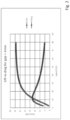
- the lift force for the arrangement shown in Fig. 1 is a function of the magnet properties, the geometry of the magnet and conductive plate, and the speed at which the magnet is travelling.
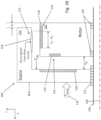
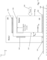
- An electric motor 100 in which this principal is employed is depicted schematically in Fig. 3A . It includes a magnetic rotor assembly 102 and a coil stator assembly 104, both of which are mounted on a shaft 106 (or hub assembly) having a longitudinal axis 108.
- the magnetic rotor assembly 102 is supported on the shaft 106 through bearings 110 which enable the magnetic rotor assembly 102 to rotate about the shaft but do not permit it to move along the shaft in an axial direction.
- the coil stator assembly 104 on the other hand is mounted on the shaft 106 through a system of linear bearings 112 that permit the coil stator assembly 104 to move back and forth along the shaft in an axial direction but do not permit it to rotate about the shaft.
- the magnetic rotor assembly 102 includes two magnet arrays, namely, a torque-generating magnet array 114 and a lift-generating magnet array 116.
- the torque-generating magnet array 114 is formed by permanent magnets 118 arranged around the perimeter of the magnetic rotor assembly 102 and with their magnetization directions pointing in a radial direction with respect to the axis of rotation of the rotor assembly.
- the magnets may be identically shaped and identically sized elements that are evenly spaced around the rotor assembly with their magnetization directions switching between a positive radial direction and negative radial direction.
- the magnetization directions may be arranged to form a Halbach array.
- the different ways of arranging the permanent magnets of rotor assembly are well known to person skilled in the art.
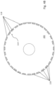
- the lift-generating magnet array 116 is formed by permanent magnets 120 arranged in a circular pattern on the face of the magnetic rotor assembly 102 that faces the coil stator assembly 104.
- the permanent magnets 120 of the lift-generating magnet array 116 are arranged so that their magnetization directions are all pointing in an axial direction with a pattern of N-S-N-S around the array.
- other patterns could be used such as N-N-S-S-N-N-S-S... or a Halbach array to name just two of other possible examples.
- the coil stator assembly 104 has a cylindrically shaped outer wall 105 surrounding the magnetic rotor assembly 102 and on the inner side of which are mounted an array of evenly spaced coils 124 of a coil array 122 encircling the rotational axis 108.
- the coils 124 of the coil array 122 are arranged to be opposite to the magnets 118 of the magnet array 114 with their axes radially directed.
- a ring of conductive material or an annularly shaped conductive plate 128 (e.g. aluminum plate) that encircles the rotational axis.
- the body of the coil stator assembly 104 can be made of aluminum (or some electrically conductive material) in which case no separate annularly shaped conductive plate is required but rather the body of the coil stator assembly itself can serve as the conductive ring.
- the spring assembly 130 for providing a return force against the backside of the coil stator assembly 104 that resists leftward movement of the coil stator assembly (i.e., movement of the coil stator assembly away from the magnetic rotor assembly).
- the spring assembly 130 pushes the coil stator assembly 104 towards the magnetic rotor assembly and against a stop (not shown) at which position the drive coil array and the torque-generating magnet array have maximum overlap with each other.
- the spring assembly 130 includes a constant force spring for which the generated force is substantially constant over a range of operation; however, springs with other force characteristics could be used.
- means other than springs could be used to generate the return force.
- the movement of the lift-generating magnet array 116 over the conducting plate 128 as the magnetic rotor assembly 102 rotates produces a force, Fiift, on the coil stator assembly 104 pushing it on its linear bearing assembly 112 to the left and away from the magnetic rotor assembly 102 thereby increasing the gap, x air , between the two, as illustrated by Fig. 3B .
- the gap x air increases by an amount that depends on the strength of the lift array, the conductive material properties, and the spring force.
- F lift decreases until it equals the force applied by the spring assembly.
- Kt x NI L 0 ⁇ x d B
- L 0 the length of maximum overlap between the coil and the magnet
- (L 0 -x d ) the "engagement length" or the measure of the amount of overlap when the coil has moved a distance x d away from maximum overlap
- N the number of windings in the coil
- I the current through the coil
- B the field strength of the magnet as seen by the coil.
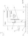
- FIG. 6A Another embodiment is illustrated by Fig. 6A in which a magnetic rotor assembly 140, which holds an array of torque-generating permanent magnets 142, surrounds a coil stator assembly 144, which holds an array of coils 146.
- the design is very similar to that of Figs. 3A-B in that there is a lift-generating magnet array 148 on an inner sidewall of the magnetic rotor assembly 140 with the magnetization directions of the magnets axially oriented and a conductive plate 150 supported by the coil stator assembly 144 so that it faces the lift-generating magnet array 148.
- the magnetic rotor assembly 140 is supported on a shaft 154 (or hub) by a bearing assembly 152 that allows it to rotate about the longitudinal axis of the shaft 154 but not move in an axial direction along that shaft.
- the coil stator assembly 144 is supported on the shaft 154 by a linear bearing assembly 160 allowing it to move back and forth in an axial direction but not rotate about that shaft 154.
- the spring assembly 130 exerts a force against the backside of the coil stator assembly 130.
- the rotating lift magnet array 148 on the magnetic rotor assembly 140 induces eddy currents in the conductive plate 150 which moves the coil stator assembly 144 to the right, decreasing the magnetic engagement length and thereby reducing the torque constant.
- FIG. 6B An arrangement similar to that illustrated by Fig. 6A is shown in Fig. 6B .
- the coil stator assembly 144 is stationary on the shaft 154 (i.e., it can neither rotate or move longitudinally) and the magnet rotor assembly 140 is supported on the shaft 154 by a bearing assembly 153 that enables it to both rotate about the shaft and move back and forth longitudinally on the shaft.
- the spring assembly 130 exerts a restorative force against the backside of the magnetic rotor assembly 140.
- Fig. 7 shows an embodiment that is similar to that illustrated by Fig. 6A except the function performed by the lift magnet array is instead performed by the drive coils 160.
- the drive coils 161 extend from the outer circumference of the coil stator assembly 164 over onto the front face 162 of the coil stator assembly 164 where they also generate a magnetic field directed axially and toward the conductive plate 166 on the magnetic rotor assembly 140. That axially directed magnetic field induces eddy currents in the rotating conductive plate 166 thereby generating a lift force that pushes the coil stator assembly 164 to the right against the spring 130 and to a new location depending on the rate of rotation.
- Fig. 8 shows an embodiment that is similar to that illustrated by Fig. 7 except instead of using the drive coils 170 to generate the field that induces the lift force, separate lift-generating coils 172 are used.
- the lift-generating coils 172 arrayed around the coil stator assembly 164 and in alignment with the conductive plate 166.
- the lift coils are equal in number to the drive coils and they receive the same drive signal.
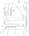
- the magnetic rotor assembly 800 carries the torque-generating magnet array 802 and it rotates within the coil stator assembly 804 that carries the drive coil array 806.
- the magnetic rotor assembly 800 is mounted on the hub assembly 154 through bearings 808 which enable it to rotate about the rotational axis 108 of the shaft 154.
- the coil stator assembly 804 is supported on the shaft 154 by a set of linear bearings 810 that permit it to move back and forth along the shaft 154 in an axial direction but do not permit it to rotate about the shaft.
- the non-rotating coil stator assembly 804 also includes the lift-generating coil array 812 on its backside 814, i.e., the side facing away from the magnetic rotor assembly 800.
- the disk 816 includes an annularly shaped conductive plate 818 that faces the lift-generating coil array 812 on the backside of the coil stator assembly 804.
- the spring assembly 130 pushes against the coil stator assembly 804 urging it towards the disk 816 and against a stop (not shown) when no signal is applied to the lift-generating coil array 812.
- the signals that drive the lift-generating coil array 812 are the same as the drive signals that drive the drive coil array 806. (The lift-generating coil array 812 could be driven separately by different signals.)
- the drive signals applied to the lift-generating array will produce a magnetic field at the conductive plate 818 that changes in accordance with the changing drive signals. This will induce eddy currents in the conductive plate which will, in turn, produce a lift force that pushes the coil stator assembly 804 away from the disk 816 and against the return force produced by the spring assembly 130, as previously described.
- FIG. 10 depicts an axial flux motor 200 that employs a lift magnet array 202 to vary the width, x air , of the gap between the drive coils 204 and the torque-generating magnets 206 of the magnetic rotor assembly 208.
- the coil stator assembly 210 has an array of drive coils 204 arrayed around the periphery of the coil stator assembly 210.
- the magnets of the magnet array have their magnetization directions axially directed in some pattern such as, without limitation: N-S-N-S-N..; 2N-2S-2N-2S...; or a Halbach array.
- On a corresponding location of the opposing face of the coil stator assembly (the same face on which the drive coils are located), there is a conductive plate 212.
- the motor of Fig. 10 operates the same as has been previously described for the other embodiments with certain numbered elements performing the functions of previously described like-numbered elements.
Landscapes
- Engineering & Computer Science (AREA)
- Power Engineering (AREA)
- Architecture (AREA)
- Civil Engineering (AREA)
- Structural Engineering (AREA)
- Linear Motors (AREA)
- Permanent Magnet Type Synchronous Machine (AREA)
- Roof Covering Using Slabs Or Stiff Sheets (AREA)
- Connection Of Motors, Electrical Generators, Mechanical Devices, And The Like (AREA)
Claims (15)
- Elektromotor (100, 200), umfassend:ein erstes Teilsystem und ein zweites Teilsystem, wobei eines des ersten und des zweiten Teilsystems eine Magnetrotorbaugruppe (102, 140, 208, 800) umfasst und das andere des ersten und des zweiten Teilsystems eine Spulenstatorbaugruppe (104, 144, 164, 210, 804) umfasst;eine Nabenbaugruppe (106, 154), die die Magnetrotorbaugruppe und die Spulenstatorbaugruppe lagert und eine Drehachse (108) definiert; undeine Lagerbaugruppe (110, 112, 152, 153, 160, 808, 810), die mindestens eines des ersten und des zweiten Teilsystems auf der Nabenbaugruppe lagert,wobei die Magnetrotorbaugruppe eine Reihe von drehmomenterzeugenden Magneten (114, 206, 802) umfasst;wobei die Spulenstatorbaugruppe eine Reihe von Antriebsspulen umfasst, die der Reihe von drehmomenterzeugenden Magneten der Magnetrotorbaugruppe gegenüberliegen;wobei das erste Teilsystem eine Reihe von Auftrieb erzeugenden Elementen (116, 148, 202, 812) zum Erzeugen von axial ausgerichteten Magnetfeldern umfasst;wobei das zweite Teilsystem einen elektrisch leitfähigen Bereich (128, 150, 166, 212, 818) umfasst, der mit der Reihe von Auftrieb erzeugenden Elementen des ersten Teilsystems ausgerichtet ist und diesen gegenüberliegt, wobei die Reihe von Auftrieb erzeugenden Elementen und der elektrisch leitfähige Bereich in der axialen Richtung um einen Trennabstand voneinander getrennt sind; undwobei die Lagerbaugruppe der Magnetrotorbaugruppe erlaubt, sich um die Drehachse der Nabenbaugruppe zu drehen, und mindestens einem des ersten oder des zweiten Teilsystems erlaubt, sich in Längsrichtung entlang der Drehachse zu bewegen, um zu ermöglichen, dass sich der Trennabstand der Magnetrotorbaugruppe und der Spulenstatorbaugruppe in Reaktion auf eine Auftriebskraft verändert, die durch Wirbelströme erzeugt wird, die in dem elektrisch leitfähigen Bereich durch die Bewegung der Reihe von Auftrieb erzeugenden Elementen und des elektrisch leitfähigen Bereichs in Bezug zueinander induziert werden; undwobei sich bei sich erhöhender Drehgeschwindigkeit der Magnetrotorbaugruppe der Trennabstand erhöht, was eine Verringerung der Magnetkopplung zwischen der Reihe von drehmomenterzeugenden Magneten und der Reihe von Antriebsspulen bewirkt.
- Elektromotor nach Anspruch 1, wobei die Lagerbaugruppe das erste Teilsystem auf der Nabenbaugruppe lagert.
- Elektromotor nach Anspruch 1, wobei die Lagerbaugruppe das zweite Teilsystem auf der Nabenbaugruppe lagert.
- Elektromotor nach Anspruch 1, wobei:
die Lagerbaugruppe sowohl die Magnetrotorbaugruppe als auch die Spulenstatorbaugruppe auf der Nabenbaugruppe lagert; und die Lagerbaugruppe der Magnetrotorbaugruppe ermöglicht, sich um die Drehachse der Nabenbaugruppe zu drehen, und eine lineare Bewegung der Spulenstatorbaugruppe entlang der Drehachse der Nabenbaugruppe ermöglicht. - Elektromotor nach Anspruch 1, wobei das erste Teilsystem die Magnetrotorbaugruppe umfasst und das zweite Teilsystem die Spulenstatorbaugruppe umfasst.
- Elektromotor nach Anspruch 1, wobei das erste Teilsystem die Spulenstatorbaugruppe umfasst und das zweite Teilsystem die Magnetrotorbaugruppe umfasst.
- Elektromotor nach Anspruch 1, wobei die Reihe von Auftrieb erzeugenden Elementen eine Reihe von Permanentmagneten (120, 214) ist.
- Elektromotor nach Anspruch 1, wobei die Reihe von Auftrieb erzeugenden Elementen eine Reihe von elektrischen Spulen (204, 812) ist.
- Elektromotor nach Anspruch 1, wobei die Lagerbaugruppe eine Drehlagerbaugruppe (110) umfasst, die die Magnetrotorbaugruppe auf der Nabenbaugruppe lagert.
- Elektromotor nach Anspruch 9, wobei die Lagerbaugruppe eine Linearlagerbaugruppe (112) umfasst, die die Spulenstatorbaugruppe auf der Nabenbaugruppe lagert und eine lineare Bewegung entlang der Nabe in einer Richtung der Drehachse ermöglicht.
- Elektromotor nach Anspruch 1, wobei die Lagerbaugruppe die Magnetrotorbaugruppe auf der Nabenbaugruppe lagert und der Magnetrotorbaugruppe erlaubt, sich um die Drehachse zu drehen und sich in Längsrichtung entlang der Drehachse vor und zurück zu bewegen.
- Elektromotor nach Anspruch 1, wobei das zweite Teilsystem eine ringförmig geformte leitfähige Platte umfasst, die den elektrisch leitfähigen Bereich bildet.
- Elektromotor nach Anspruch 1, wobei die Magnetrotorbaugruppe und die Spulenstatorbaugruppe einen Radialflussmotor bilden.
- Elektromotor nach Anspruch 1, wobei die Magnetrotorbaugruppe und die Spulenstatorbaugruppe einen Axialflussmotor (200) bilden.
- Elektromotor nach Anspruch 1, wobei der Elektromotor dazu ausgelegt ist, eine der Auftriebskraft entgegenwirkende Rückstellkraft auf eine der Magnetrotorbaugruppe oder der Spulenstatorbaugruppe aufzubringen, um die Veränderung des Trennabstands zwischen der Reihe von Auftrieb erzeugenden Elementen und dem elektrisch leitfähigen Bereich zu begrenzen.
Applications Claiming Priority (3)
| Application Number | Priority Date | Filing Date | Title |
|---|---|---|---|
| US201762554328P | 2017-09-05 | 2017-09-05 | |
| US15/927,328 US10763713B2 (en) | 2017-09-05 | 2018-03-21 | Permanent magnet motor with passively controlled variable rotor/stator alignment |
| PCT/US2018/044955 WO2019050642A1 (en) | 2017-09-05 | 2018-08-02 | PERMANENT MAGNET MOTOR WITH ROTOR / STATOR VARIABLE ALIGNMENT WITH PASSIVE CONTROL |
Publications (3)
| Publication Number | Publication Date |
|---|---|
| EP3679640A1 EP3679640A1 (de) | 2020-07-15 |
| EP3679640C0 EP3679640C0 (de) | 2024-06-19 |
| EP3679640B1 true EP3679640B1 (de) | 2024-06-19 |
Family
ID=65517556
Family Applications (1)
| Application Number | Title | Priority Date | Filing Date |
|---|---|---|---|
| EP18755653.5A Active EP3679640B1 (de) | 2017-09-05 | 2018-08-02 | Permanentmagnetmotor mit passiv gesteuerter variabler rotor-/statorausrichtung |
Country Status (7)
| Country | Link |
|---|---|
| US (1) | US10465388B2 (de) |
| EP (1) | EP3679640B1 (de) |
| JP (1) | JP7194457B2 (de) |
| KR (1) | KR20200039811A (de) |
| CN (2) | CN111213307B (de) |
| CA (1) | CA3252773A1 (de) |
| WO (1) | WO2019050642A1 (de) |
Families Citing this family (13)
| Publication number | Priority date | Publication date | Assignee | Title |
|---|---|---|---|---|
| US12134897B2 (en) | 2018-01-17 | 2024-11-05 | Leaffilter North, Llc | Rear receivers for use with systems and methods for modular platforms for gutter guard systems with interchangeable components |
| US12134898B2 (en) | 2018-01-17 | 2024-11-05 | Leaffilter North, Llc | Rear receivers for use with systems and methods for modular platforms for gutter guard systems with interchangeable components |
| US12158003B2 (en) | 2018-01-17 | 2024-12-03 | Leaffilter North, Llc | Systems and methods for modular platform for gutter guard systems with interchangeable components |
| US11078670B2 (en) * | 2018-01-17 | 2021-08-03 | Leaffilter North, Llc | Systems and methods for modular platform for gutter guard systems with interchangeable components |
| US11015348B2 (en) | 2018-01-17 | 2021-05-25 | Leaffilter North, Llc | Rear receiver and methods for use with modular platform for gutter guard systems with interchangeable components |
| US10443244B2 (en) * | 2018-01-17 | 2019-10-15 | Leaffilter North, Llc | Main bodies and methods for use with modular platform for gutter guard systems with interchangeable components |
| US10900234B2 (en) * | 2018-09-21 | 2021-01-26 | Brock Dressel | Gutter cover system |
| DE102020114856B3 (de) * | 2020-06-04 | 2021-09-23 | Schaeffler Technologies AG & Co. KG | Elektrische Radialflussmaschine und Antriebsstrang |
| US12091861B2 (en) * | 2021-05-05 | 2024-09-17 | Stephane Brochu | Gutter assembly and gutter cover therefor |
| US12091860B2 (en) * | 2021-07-15 | 2024-09-17 | Stephane Brochu | Gutter assembly and method for installing a gutter |
| US12398565B2 (en) * | 2022-09-19 | 2025-08-26 | Leaffilter North, Llc | Screens for use with gutter guard systems |
| CN115580053A (zh) * | 2022-10-14 | 2023-01-06 | 珠海格力电器股份有限公司 | 一种电机 |
| US12305398B2 (en) | 2023-06-01 | 2025-05-20 | GMOLAH, Inc | Gutter and downspout cleaning device and method |
Family Cites Families (20)
| Publication number | Priority date | Publication date | Assignee | Title |
|---|---|---|---|---|
| GB1051591A (en) * | 1963-07-12 | 1966-12-14 | Alternating current generator | |
| US4820407A (en) * | 1987-04-24 | 1989-04-11 | Cpi Sales, Inc. | Solids screens |
| JPH0686503A (ja) * | 1992-09-03 | 1994-03-25 | Hitachi Ltd | モータ、ポリゴンミラーモータ、ディスク駆動モータ |
| US5406754A (en) * | 1993-02-03 | 1995-04-18 | Cosby; Lloyd N. | Drain gutter debris guard and method of making |
| JP4351792B2 (ja) | 2000-07-10 | 2009-10-28 | 株式会社東芝 | スタータを兼用したオルタネータ |
| US6598352B2 (en) * | 2001-08-07 | 2003-07-29 | Edward A. Higginbotham | Self cleaning gutter shield |
| US6641378B2 (en) * | 2001-11-13 | 2003-11-04 | William D. Davis | Pump with electrodynamically supported impeller |
| US7310912B2 (en) * | 2003-09-16 | 2007-12-25 | Lenney Robert C | Rain gutter debris preclusion device |
| US7913458B2 (en) * | 2004-05-21 | 2011-03-29 | Edward Alan Higginbotham | Self cleaning gutter shield |
| US8474192B2 (en) * | 2008-10-13 | 2013-07-02 | Southeastern Metals Manufacturing Company, Inc. | Screened gutter protection |
| JP5205594B2 (ja) * | 2006-03-16 | 2013-06-05 | 日産自動車株式会社 | 回転電機 |
| KR101641396B1 (ko) * | 2008-09-30 | 2016-07-20 | 티에치케이 가부시끼가이샤 | 직선ㆍ회전 복합 액추에이터 |
| JP5402009B2 (ja) | 2009-01-17 | 2014-01-29 | 日産自動車株式会社 | 可変特性回転電機 |
| US8479454B2 (en) * | 2009-09-23 | 2013-07-09 | Gutterglove, Inc. | Supported mesh debris preclusion system for gutters |
| US9010030B2 (en) * | 2013-08-05 | 2015-04-21 | L.B. Plastics Inc. | Gutter guard apparatuses and methods |
| FR3022706B1 (fr) * | 2014-06-20 | 2017-11-17 | Whylot | Moteur synchrone electromagnetique a flux magnetiques combines axial et radial. |
| CN105471212B (zh) * | 2014-09-04 | 2018-07-06 | 中国科学院宁波材料技术与工程研究所 | 一种旋转直线永磁电机 |
| US9127463B1 (en) * | 2014-09-22 | 2015-09-08 | Daniel E. Feldhaus | Gutter debris cover |
| EP3542079B1 (de) * | 2016-11-17 | 2021-09-29 | Baker Hughes Holdings LLC | Axiales aktives magnetlager für die langsamlaufregelung der welle |
| CN106921227A (zh) * | 2017-04-05 | 2017-07-04 | 丁士来 | 一种无换向器永磁直流电机 |
-
2018
- 2018-08-02 EP EP18755653.5A patent/EP3679640B1/de active Active
- 2018-08-02 CN CN201880067386.4A patent/CN111213307B/zh active Active
- 2018-08-02 CN CN202211006533.1A patent/CN115395688A/zh not_active Withdrawn
- 2018-08-02 JP JP2020513528A patent/JP7194457B2/ja active Active
- 2018-08-02 WO PCT/US2018/044955 patent/WO2019050642A1/en not_active Ceased
- 2018-08-02 KR KR1020207009748A patent/KR20200039811A/ko not_active Ceased
- 2018-09-05 US US16/121,964 patent/US10465388B2/en active Active
- 2018-09-05 CA CA3252773A patent/CA3252773A1/en active Pending
Also Published As
| Publication number | Publication date |
|---|---|
| WO2019050642A1 (en) | 2019-03-14 |
| EP3679640C0 (de) | 2024-06-19 |
| EP3679640A1 (de) | 2020-07-15 |
| US20190071874A1 (en) | 2019-03-07 |
| JP2020532941A (ja) | 2020-11-12 |
| CA3252773A1 (en) | 2025-10-30 |
| CA3016527A1 (en) | 2019-03-05 |
| JP7194457B2 (ja) | 2022-12-22 |
| CN111213307B (zh) | 2022-09-09 |
| CN111213307A (zh) | 2020-05-29 |
| CN115395688A (zh) | 2022-11-25 |
| US10465388B2 (en) | 2019-11-05 |
| KR20200039811A (ko) | 2020-04-16 |
Similar Documents
| Publication | Publication Date | Title |
|---|---|---|
| EP3679640B1 (de) | Permanentmagnetmotor mit passiv gesteuerter variabler rotor-/statorausrichtung | |
| US20210044165A1 (en) | Permanent Magnet Motor with Passively Controlled Variable Rotor/Stator Alignment | |
| US20130187504A1 (en) | Dynamo-electric machine | |
| US20090001831A1 (en) | Axial Field Electric Motor and Method | |
| JP2001520498A (ja) | リニア電磁機械 | |
| EP3163726B1 (de) | Flussregelung einer elektrischen permanentmagnetmaschine | |
| JP7149968B2 (ja) | 改良型磁気クラッチアセンブリ | |
| US20240250568A1 (en) | Axial Flux Motor | |
| US6809451B1 (en) | Galvanometer motor with composite rotor assembly | |
| CN110235340B (zh) | 永磁激励的旋转电机的制造方法和拆卸方法 | |
| JP5673438B2 (ja) | 回転電機のロータ構造 | |
| WO1995027326A1 (en) | Adjustable airgap motor/generator for flywheel system | |
| RU2545167C1 (ru) | Синхронный электродвигатель | |
| CN103229399A (zh) | 低速多极同步发电机 | |
| Ueno et al. | A 5-dof active controlled disk type pm motor with cylindrical flux paths | |
| US11563362B2 (en) | Rotating electrical machine and aircraft having said machine | |
| JP2012060709A (ja) | 永久磁石型モータ | |
| RU2596145C1 (ru) | Шаговый электродвигатель | |
| RU2516270C1 (ru) | Магнитоэлектрическая машина | |
| EP3701623B1 (de) | Elektrische maschine mit einem beweglichen selbstlenkenden hilfsstator | |
| SU748702A1 (ru) | Электродвигатель | |
| EP3490121B1 (de) | Drehmotor und kontaktfreier generator | |
| CN113206554A (zh) | 双自由度球形无刷直流电动机 | |
| JPS63161854A (ja) | 磁石式ロ−タ構造 | |
| JP2000347122A (ja) | ラジアルギャップ型動圧軸駆動部 |
Legal Events
| Date | Code | Title | Description |
|---|---|---|---|
| STAA | Information on the status of an ep patent application or granted ep patent |
Free format text: STATUS: UNKNOWN |
|
| STAA | Information on the status of an ep patent application or granted ep patent |
Free format text: STATUS: THE INTERNATIONAL PUBLICATION HAS BEEN MADE |
|
| PUAI | Public reference made under article 153(3) epc to a published international application that has entered the european phase |
Free format text: ORIGINAL CODE: 0009012 |
|
| STAA | Information on the status of an ep patent application or granted ep patent |
Free format text: STATUS: REQUEST FOR EXAMINATION WAS MADE |
|
| 17P | Request for examination filed |
Effective date: 20200330 |
|
| AK | Designated contracting states |
Kind code of ref document: A1 Designated state(s): AL AT BE BG CH CY CZ DE DK EE ES FI FR GB GR HR HU IE IS IT LI LT LU LV MC MK MT NL NO PL PT RO RS SE SI SK SM TR |
|
| AX | Request for extension of the european patent |
Extension state: BA ME |
|
| DAV | Request for validation of the european patent (deleted) | ||
| DAX | Request for extension of the european patent (deleted) | ||
| STAA | Information on the status of an ep patent application or granted ep patent |
Free format text: STATUS: EXAMINATION IS IN PROGRESS |
|
| 17Q | First examination report despatched |
Effective date: 20211206 |
|
| P01 | Opt-out of the competence of the unified patent court (upc) registered |
Effective date: 20230527 |
|
| GRAP | Despatch of communication of intention to grant a patent |
Free format text: ORIGINAL CODE: EPIDOSNIGR1 |
|
| STAA | Information on the status of an ep patent application or granted ep patent |
Free format text: STATUS: GRANT OF PATENT IS INTENDED |
|
| RIC1 | Information provided on ipc code assigned before grant |
Ipc: E04D 13/076 20060101ALI20231215BHEP Ipc: H02K 21/02 20060101AFI20231215BHEP |
|
| INTG | Intention to grant announced |
Effective date: 20240112 |
|
| GRAS | Grant fee paid |
Free format text: ORIGINAL CODE: EPIDOSNIGR3 |
|
| GRAA | (expected) grant |
Free format text: ORIGINAL CODE: 0009210 |
|
| STAA | Information on the status of an ep patent application or granted ep patent |
Free format text: STATUS: THE PATENT HAS BEEN GRANTED |
|
| AK | Designated contracting states |
Kind code of ref document: B1 Designated state(s): AL AT BE BG CH CY CZ DE DK EE ES FI FR GB GR HR HU IE IS IT LI LT LU LV MC MK MT NL NO PL PT RO RS SE SI SK SM TR |
|
| REG | Reference to a national code |
Ref country code: GB Ref legal event code: FG4D |
|
| REG | Reference to a national code |
Ref country code: CH Ref legal event code: EP |
|
| REG | Reference to a national code |
Ref country code: DE Ref legal event code: R096 Ref document number: 602018070771 Country of ref document: DE |
|
| U01 | Request for unitary effect filed |
Effective date: 20240716 |
|
| P04 | Withdrawal of opt-out of the competence of the unified patent court (upc) registered |
Free format text: CASE NUMBER: APP_43022/2024 Effective date: 20240722 |
|
| U07 | Unitary effect registered |
Designated state(s): AT BE BG DE DK EE FI FR IT LT LU LV MT NL PT SE SI Effective date: 20240725 |
|
| U20 | Renewal fee for the european patent with unitary effect paid |
Year of fee payment: 7 Effective date: 20240827 |
|
| PG25 | Lapsed in a contracting state [announced via postgrant information from national office to epo] |
Ref country code: HR Free format text: LAPSE BECAUSE OF FAILURE TO SUBMIT A TRANSLATION OF THE DESCRIPTION OR TO PAY THE FEE WITHIN THE PRESCRIBED TIME-LIMIT Effective date: 20240619 |
|
| PG25 | Lapsed in a contracting state [announced via postgrant information from national office to epo] |
Ref country code: GR Free format text: LAPSE BECAUSE OF FAILURE TO SUBMIT A TRANSLATION OF THE DESCRIPTION OR TO PAY THE FEE WITHIN THE PRESCRIBED TIME-LIMIT Effective date: 20240920 |
|
| PG25 | Lapsed in a contracting state [announced via postgrant information from national office to epo] |
Ref country code: NO Free format text: LAPSE BECAUSE OF FAILURE TO SUBMIT A TRANSLATION OF THE DESCRIPTION OR TO PAY THE FEE WITHIN THE PRESCRIBED TIME-LIMIT Effective date: 20240919 Ref country code: HR Free format text: LAPSE BECAUSE OF FAILURE TO SUBMIT A TRANSLATION OF THE DESCRIPTION OR TO PAY THE FEE WITHIN THE PRESCRIBED TIME-LIMIT Effective date: 20240619 Ref country code: GR Free format text: LAPSE BECAUSE OF FAILURE TO SUBMIT A TRANSLATION OF THE DESCRIPTION OR TO PAY THE FEE WITHIN THE PRESCRIBED TIME-LIMIT Effective date: 20240920 Ref country code: RS Free format text: LAPSE BECAUSE OF FAILURE TO SUBMIT A TRANSLATION OF THE DESCRIPTION OR TO PAY THE FEE WITHIN THE PRESCRIBED TIME-LIMIT Effective date: 20240919 |
|
| P05 | Withdrawal of opt-out of the competence of the unified patent court (upc) changed |
Free format text: CASE NUMBER: APP_43022/2024 Effective date: 20240725 |
|
| PG25 | Lapsed in a contracting state [announced via postgrant information from national office to epo] |
Ref country code: PL Free format text: LAPSE BECAUSE OF FAILURE TO SUBMIT A TRANSLATION OF THE DESCRIPTION OR TO PAY THE FEE WITHIN THE PRESCRIBED TIME-LIMIT Effective date: 20240619 |
|
| PG25 | Lapsed in a contracting state [announced via postgrant information from national office to epo] |
Ref country code: IS Free format text: LAPSE BECAUSE OF FAILURE TO SUBMIT A TRANSLATION OF THE DESCRIPTION OR TO PAY THE FEE WITHIN THE PRESCRIBED TIME-LIMIT Effective date: 20241019 |
|
| PG25 | Lapsed in a contracting state [announced via postgrant information from national office to epo] |
Ref country code: CZ Free format text: LAPSE BECAUSE OF FAILURE TO SUBMIT A TRANSLATION OF THE DESCRIPTION OR TO PAY THE FEE WITHIN THE PRESCRIBED TIME-LIMIT Effective date: 20240619 |
|
| PG25 | Lapsed in a contracting state [announced via postgrant information from national office to epo] |
Ref country code: SK Free format text: LAPSE BECAUSE OF FAILURE TO SUBMIT A TRANSLATION OF THE DESCRIPTION OR TO PAY THE FEE WITHIN THE PRESCRIBED TIME-LIMIT Effective date: 20240619 Ref country code: RO Free format text: LAPSE BECAUSE OF FAILURE TO SUBMIT A TRANSLATION OF THE DESCRIPTION OR TO PAY THE FEE WITHIN THE PRESCRIBED TIME-LIMIT Effective date: 20240619 |
|
| PG25 | Lapsed in a contracting state [announced via postgrant information from national office to epo] |
Ref country code: SM Free format text: LAPSE BECAUSE OF FAILURE TO SUBMIT A TRANSLATION OF THE DESCRIPTION OR TO PAY THE FEE WITHIN THE PRESCRIBED TIME-LIMIT Effective date: 20240619 Ref country code: ES Free format text: LAPSE BECAUSE OF FAILURE TO SUBMIT A TRANSLATION OF THE DESCRIPTION OR TO PAY THE FEE WITHIN THE PRESCRIBED TIME-LIMIT Effective date: 20240619 |
|
| PG25 | Lapsed in a contracting state [announced via postgrant information from national office to epo] |
Ref country code: SM Free format text: LAPSE BECAUSE OF FAILURE TO SUBMIT A TRANSLATION OF THE DESCRIPTION OR TO PAY THE FEE WITHIN THE PRESCRIBED TIME-LIMIT Effective date: 20240619 Ref country code: SK Free format text: LAPSE BECAUSE OF FAILURE TO SUBMIT A TRANSLATION OF THE DESCRIPTION OR TO PAY THE FEE WITHIN THE PRESCRIBED TIME-LIMIT Effective date: 20240619 Ref country code: RO Free format text: LAPSE BECAUSE OF FAILURE TO SUBMIT A TRANSLATION OF THE DESCRIPTION OR TO PAY THE FEE WITHIN THE PRESCRIBED TIME-LIMIT Effective date: 20240619 Ref country code: PL Free format text: LAPSE BECAUSE OF FAILURE TO SUBMIT A TRANSLATION OF THE DESCRIPTION OR TO PAY THE FEE WITHIN THE PRESCRIBED TIME-LIMIT Effective date: 20240619 Ref country code: IS Free format text: LAPSE BECAUSE OF FAILURE TO SUBMIT A TRANSLATION OF THE DESCRIPTION OR TO PAY THE FEE WITHIN THE PRESCRIBED TIME-LIMIT Effective date: 20241019 Ref country code: ES Free format text: LAPSE BECAUSE OF FAILURE TO SUBMIT A TRANSLATION OF THE DESCRIPTION OR TO PAY THE FEE WITHIN THE PRESCRIBED TIME-LIMIT Effective date: 20240619 Ref country code: CZ Free format text: LAPSE BECAUSE OF FAILURE TO SUBMIT A TRANSLATION OF THE DESCRIPTION OR TO PAY THE FEE WITHIN THE PRESCRIBED TIME-LIMIT Effective date: 20240619 |
|
| REG | Reference to a national code |
Ref country code: CH Ref legal event code: PL |
|
| PG25 | Lapsed in a contracting state [announced via postgrant information from national office to epo] |
Ref country code: MC Free format text: LAPSE BECAUSE OF FAILURE TO SUBMIT A TRANSLATION OF THE DESCRIPTION OR TO PAY THE FEE WITHIN THE PRESCRIBED TIME-LIMIT Effective date: 20240619 Ref country code: CH Free format text: LAPSE BECAUSE OF NON-PAYMENT OF DUE FEES Effective date: 20240831 |
|
| PLBE | No opposition filed within time limit |
Free format text: ORIGINAL CODE: 0009261 |
|
| STAA | Information on the status of an ep patent application or granted ep patent |
Free format text: STATUS: NO OPPOSITION FILED WITHIN TIME LIMIT |
|
| 26N | No opposition filed |
Effective date: 20250320 |
|
| PG25 | Lapsed in a contracting state [announced via postgrant information from national office to epo] |
Ref country code: IE Free format text: LAPSE BECAUSE OF NON-PAYMENT OF DUE FEES Effective date: 20240802 |
|
| U20 | Renewal fee for the european patent with unitary effect paid |
Year of fee payment: 8 Effective date: 20250827 |
|
| PGFP | Annual fee paid to national office [announced via postgrant information from national office to epo] |
Ref country code: GB Payment date: 20250827 Year of fee payment: 8 |
|
| PG25 | Lapsed in a contracting state [announced via postgrant information from national office to epo] |
Ref country code: CY Free format text: LAPSE BECAUSE OF FAILURE TO SUBMIT A TRANSLATION OF THE DESCRIPTION OR TO PAY THE FEE WITHIN THE PRESCRIBED TIME-LIMIT; INVALID AB INITIO Effective date: 20180802 |
|
| PG25 | Lapsed in a contracting state [announced via postgrant information from national office to epo] |
Ref country code: HU Free format text: LAPSE BECAUSE OF FAILURE TO SUBMIT A TRANSLATION OF THE DESCRIPTION OR TO PAY THE FEE WITHIN THE PRESCRIBED TIME-LIMIT; INVALID AB INITIO Effective date: 20180802 |