EP3679233B1 - Boitier d'accessoires pour turbomachine - Google Patents
Boitier d'accessoires pour turbomachine Download PDFInfo
- Publication number
- EP3679233B1 EP3679233B1 EP18774097.2A EP18774097A EP3679233B1 EP 3679233 B1 EP3679233 B1 EP 3679233B1 EP 18774097 A EP18774097 A EP 18774097A EP 3679233 B1 EP3679233 B1 EP 3679233B1
- Authority
- EP
- European Patent Office
- Prior art keywords
- support
- faces
- box according
- box
- housing
- Prior art date
- Legal status (The legal status is an assumption and is not a legal conclusion. Google has not performed a legal analysis and makes no representation as to the accuracy of the status listed.)
- Active
Links
Images

Classifications
-
- F—MECHANICAL ENGINEERING; LIGHTING; HEATING; WEAPONS; BLASTING
- F02—COMBUSTION ENGINES; HOT-GAS OR COMBUSTION-PRODUCT ENGINE PLANTS
- F02C—GAS-TURBINE PLANTS; AIR INTAKES FOR JET-PROPULSION PLANTS; CONTROLLING FUEL SUPPLY IN AIR-BREATHING JET-PROPULSION PLANTS
- F02C7/00—Features, components parts, details or accessories, not provided for in, or of interest apart form groups F02C1/00 - F02C6/00; Air intakes for jet-propulsion plants
- F02C7/32—Arrangement, mounting, or driving, of auxiliaries
-
- F—MECHANICAL ENGINEERING; LIGHTING; HEATING; WEAPONS; BLASTING
- F02—COMBUSTION ENGINES; HOT-GAS OR COMBUSTION-PRODUCT ENGINE PLANTS
- F02C—GAS-TURBINE PLANTS; AIR INTAKES FOR JET-PROPULSION PLANTS; CONTROLLING FUEL SUPPLY IN AIR-BREATHING JET-PROPULSION PLANTS
- F02C7/00—Features, components parts, details or accessories, not provided for in, or of interest apart form groups F02C1/00 - F02C6/00; Air intakes for jet-propulsion plants
- F02C7/36—Power transmission arrangements between the different shafts of the gas turbine plant, or between the gas-turbine plant and the power user
-
- F—MECHANICAL ENGINEERING; LIGHTING; HEATING; WEAPONS; BLASTING
- F01—MACHINES OR ENGINES IN GENERAL; ENGINE PLANTS IN GENERAL; STEAM ENGINES
- F01D—NON-POSITIVE DISPLACEMENT MACHINES OR ENGINES, e.g. STEAM TURBINES
- F01D25/00—Component parts, details, or accessories, not provided for in, or of interest apart from, other groups
- F01D25/16—Arrangement of bearings; Supporting or mounting bearings in casings
- F01D25/162—Bearing supports
-
- F—MECHANICAL ENGINEERING; LIGHTING; HEATING; WEAPONS; BLASTING
- F02—COMBUSTION ENGINES; HOT-GAS OR COMBUSTION-PRODUCT ENGINE PLANTS
- F02C—GAS-TURBINE PLANTS; AIR INTAKES FOR JET-PROPULSION PLANTS; CONTROLLING FUEL SUPPLY IN AIR-BREATHING JET-PROPULSION PLANTS
- F02C7/00—Features, components parts, details or accessories, not provided for in, or of interest apart form groups F02C1/00 - F02C6/00; Air intakes for jet-propulsion plants
- F02C7/06—Arrangements of bearings; Lubricating
-
- F—MECHANICAL ENGINEERING; LIGHTING; HEATING; WEAPONS; BLASTING
- F05—INDEXING SCHEMES RELATING TO ENGINES OR PUMPS IN VARIOUS SUBCLASSES OF CLASSES F01-F04
- F05D—INDEXING SCHEME FOR ASPECTS RELATING TO NON-POSITIVE-DISPLACEMENT MACHINES OR ENGINES, GAS-TURBINES OR JET-PROPULSION PLANTS
- F05D2220/00—Application
- F05D2220/30—Application in turbines
- F05D2220/32—Application in turbines in gas turbines
- F05D2220/323—Application in turbines in gas turbines for aircraft propulsion, e.g. jet engines
-
- F—MECHANICAL ENGINEERING; LIGHTING; HEATING; WEAPONS; BLASTING
- F05—INDEXING SCHEMES RELATING TO ENGINES OR PUMPS IN VARIOUS SUBCLASSES OF CLASSES F01-F04
- F05D—INDEXING SCHEME FOR ASPECTS RELATING TO NON-POSITIVE-DISPLACEMENT MACHINES OR ENGINES, GAS-TURBINES OR JET-PROPULSION PLANTS
- F05D2220/00—Application
- F05D2220/30—Application in turbines
- F05D2220/32—Application in turbines in gas turbines
- F05D2220/329—Application in turbines in gas turbines in helicopters
-
- F—MECHANICAL ENGINEERING; LIGHTING; HEATING; WEAPONS; BLASTING
- F05—INDEXING SCHEMES RELATING TO ENGINES OR PUMPS IN VARIOUS SUBCLASSES OF CLASSES F01-F04
- F05D—INDEXING SCHEME FOR ASPECTS RELATING TO NON-POSITIVE-DISPLACEMENT MACHINES OR ENGINES, GAS-TURBINES OR JET-PROPULSION PLANTS
- F05D2220/00—Application
- F05D2220/70—Application in combination with
- F05D2220/76—Application in combination with an electrical generator
-
- F—MECHANICAL ENGINEERING; LIGHTING; HEATING; WEAPONS; BLASTING
- F05—INDEXING SCHEMES RELATING TO ENGINES OR PUMPS IN VARIOUS SUBCLASSES OF CLASSES F01-F04
- F05D—INDEXING SCHEME FOR ASPECTS RELATING TO NON-POSITIVE-DISPLACEMENT MACHINES OR ENGINES, GAS-TURBINES OR JET-PROPULSION PLANTS
- F05D2240/00—Components
- F05D2240/10—Stators
- F05D2240/14—Casings or housings protecting or supporting assemblies within
-
- F—MECHANICAL ENGINEERING; LIGHTING; HEATING; WEAPONS; BLASTING
- F05—INDEXING SCHEMES RELATING TO ENGINES OR PUMPS IN VARIOUS SUBCLASSES OF CLASSES F01-F04
- F05D—INDEXING SCHEME FOR ASPECTS RELATING TO NON-POSITIVE-DISPLACEMENT MACHINES OR ENGINES, GAS-TURBINES OR JET-PROPULSION PLANTS
- F05D2240/00—Components
- F05D2240/50—Bearings
-
- F—MECHANICAL ENGINEERING; LIGHTING; HEATING; WEAPONS; BLASTING
- F05—INDEXING SCHEMES RELATING TO ENGINES OR PUMPS IN VARIOUS SUBCLASSES OF CLASSES F01-F04
- F05D—INDEXING SCHEME FOR ASPECTS RELATING TO NON-POSITIVE-DISPLACEMENT MACHINES OR ENGINES, GAS-TURBINES OR JET-PROPULSION PLANTS
- F05D2240/00—Components
- F05D2240/60—Shafts
-
- F—MECHANICAL ENGINEERING; LIGHTING; HEATING; WEAPONS; BLASTING
- F05—INDEXING SCHEMES RELATING TO ENGINES OR PUMPS IN VARIOUS SUBCLASSES OF CLASSES F01-F04
- F05D—INDEXING SCHEME FOR ASPECTS RELATING TO NON-POSITIVE-DISPLACEMENT MACHINES OR ENGINES, GAS-TURBINES OR JET-PROPULSION PLANTS
- F05D2250/00—Geometry
- F05D2250/70—Shape
-
- F—MECHANICAL ENGINEERING; LIGHTING; HEATING; WEAPONS; BLASTING
- F05—INDEXING SCHEMES RELATING TO ENGINES OR PUMPS IN VARIOUS SUBCLASSES OF CLASSES F01-F04
- F05D—INDEXING SCHEME FOR ASPECTS RELATING TO NON-POSITIVE-DISPLACEMENT MACHINES OR ENGINES, GAS-TURBINES OR JET-PROPULSION PLANTS
- F05D2260/00—Function
- F05D2260/40—Transmission of power
- F05D2260/403—Transmission of power through the shape of the drive components
- F05D2260/4031—Transmission of power through the shape of the drive components as in toothed gearing
-
- F—MECHANICAL ENGINEERING; LIGHTING; HEATING; WEAPONS; BLASTING
- F05—INDEXING SCHEMES RELATING TO ENGINES OR PUMPS IN VARIOUS SUBCLASSES OF CLASSES F01-F04
- F05D—INDEXING SCHEME FOR ASPECTS RELATING TO NON-POSITIVE-DISPLACEMENT MACHINES OR ENGINES, GAS-TURBINES OR JET-PROPULSION PLANTS
- F05D2260/00—Function
- F05D2260/50—Kinematic linkage, i.e. transmission of position
- F05D2260/53—Kinematic linkage, i.e. transmission of position using gears
-
- Y—GENERAL TAGGING OF NEW TECHNOLOGICAL DEVELOPMENTS; GENERAL TAGGING OF CROSS-SECTIONAL TECHNOLOGIES SPANNING OVER SEVERAL SECTIONS OF THE IPC; TECHNICAL SUBJECTS COVERED BY FORMER USPC CROSS-REFERENCE ART COLLECTIONS [XRACs] AND DIGESTS
- Y02—TECHNOLOGIES OR APPLICATIONS FOR MITIGATION OR ADAPTATION AGAINST CLIMATE CHANGE
- Y02T—CLIMATE CHANGE MITIGATION TECHNOLOGIES RELATED TO TRANSPORTATION
- Y02T50/00—Aeronautics or air transport
- Y02T50/60—Efficient propulsion technologies, e.g. for aircraft
Definitions
- the present invention relates to the general field of gas turbines and more particularly relates to a housing for driving accessories of a gas turbine.
- the field of application of the invention is that of gas turbines for aircraft or helicopter engines, as well as for auxiliary power units (or APU for “Auxiliary Power Unit”).
- Gas turbine engines of aircraft or helicopters generally have a housing for driving several turbine accessories or ancillary equipment, such as in particular various pumps for the production of hydraulic energy, fuel supply, lubrication, electric generators for the production of electric power, etc.
- Such an accessory relay box is commonly called AGB for "Accessory GearBox”.
- an accessory relay box comprises one or more gear trains which are each composed of several toothed wheels and which are driven in rotation by a power transmission shaft, the latter being coupled to a turbine shaft.
- each accessory is generally mounted against one of the side faces of the housing and comprises a feed shaft which couples to one of the toothed wheels of the gear train(s).
- these side faces also provide a bearing support function for sealing or lubrication.
- housings for driving accessories which, to date, are mainly produced using a casting or machining process in the mass, long and costly which it is important to be able to reduce significantly.
- the present invention relates to an accessory relay box according to claim 1.
- each shaft is guided in rotation by one or more rolling bearings all carried by the same support interposed between the front and rear faces, which makes it possible to reduce the thickness (in a direction perpendicular to the front and rear faces) compared with a housing architecture of the prior art.
- the toothed wheels are arranged on either side of said support in a cantilevered assembly, i.e. all the rolling bearings supporting the toothed wheels are located on one side only of said toothed wheels unlike the assemblies of the prior art where the bearings are on either side of the toothed wheels. This thus makes it possible to not support the bearings by only one support part, to simplify the assembly of the kinematic chain, the control of the parts, the machining, etc.
- the assembly thus proposed makes it possible to dissociate the bearing support function from the other functions of the front or rear side faces, thus facilitating the design of these faces and limiting their functions to a sealing function.
- These front and rear faces can thus be easily designed without imposing a specific manufacturing technique.
- housing manufacturing is simplified since the rolling bearings are all centered in housings formed on a single part, which also reduces support machining time.
- the meshing forces are taken up by the central bearing support and the static and dynamic equipment support forces are taken up by the front and rear faces. This design makes possible a topological optimization of each of the parts due to the dissociated functions between taking up the meshing forces and the structural forces.
- said support is formed by an openwork plate having a lattice shape comprising a plurality of housings for receiving rolling bearings.
- the openings thus make it possible to reduce the mass of the support.
- the support may comprise means for attaching the housing to a casing of a gas turbine.
- the design of these means is also made simpler by the use of a single support for the bearings.
- At least one of the front and rear faces can support equipment.
- the housing and its front and rear faces supporting the equipment can be arranged in any angular orientation relative to the axis of the shaft of the turbomachine equipped with said accessory housing.
- the housing can thus be located at any point in the engine, for example at the level of the space separating the primary and secondary veins or in the surrounding nacelle, etc.
- the front and rear faces are advantageously connected to each other by a peripheral rim forming with said front and rear faces a sealed enclosure.
- the front and rear faces are formed on a single-piece housing comprising an opening for mounting said previously mentioned support.
- the housing comprises a shutter which is integral with said support and which is capable of closing the opening.
- the support comprises means for lubricating the rolling bearings and the teeth, which is made simple by the use of a single support part supporting the bearings.
- the lubrication of the kinematic chain can be carried out by a dedicated external pipe and attached to the support part by an appropriate fixing system.
- the invention also relates to a gas turbine engine for aircraft or helicopters, comprising an accessory housing as described above.
- FIGS. 1A, 1B and 1C represent a first embodiment of an accessory relay box 10 of an aircraft engine gas turbine according to the invention, the Figure 1A being a global representation of the case, the Figure 1B being an exploded representation of some of its constituent elements and the Figure 1C being an isolated representation of a support 12 of toothed wheels 14. It is understood that the invention also applies to gas turbines of helicopter engines, as well as to auxiliary power units.
- This housing 10 conventionally has a general shape of a substantially parallelepiped “banana” or “bean” with a front lateral face 16 and a rear lateral face 18 opposite the front face 16 and secured thereto by means of the support 12 interposed between the front face 16 and the rear face 18.
- the front face 16 comprises a plurality of holes 20 formed on its periphery and cooperating with holes 22 in the periphery of the support 12 and holes 24 in the periphery of the rear face 18.
- the support 12 comprises two attachment members 26 each formed of two yokes extending outside the enclosure delimited by the front 16 and rear 18 faces. These yokes allow the housing 10 to be fixed to a casing of the turbomachine.
- the housing 10 contains one or more trains (or chains) of gears formed by the toothed wheels 14 meshing together which extend parallel to the side faces 16, 18 and which conventionally have the function of driving in rotation a plurality of accessories (not shown).
- the accessories are each mounted on one of the side faces 16, 18 of the housing.
- Each accessory further comprises a feed shaft (not shown) which is driven in rotation by cooperation of shapes, for example by means of splines, with a shaft 28 carrying a toothed wheel to be driven therein ( Figure 1C ).
- a power transmission shaft (not shown) draws mechanical power from a turbine shaft (not shown in the figures) to transmit it to the various gear wheels 14 of the gear train.
- the power transmission shaft is rotationally coupled to the gear train by means of one of the gear wheels of the gear train.
- each shaft 28 carrying a toothed wheel 14 is held by one or more rolling bearings 30 which are all carried by the support 12 interposed laterally between the front 16 and rear 18 faces of the housing 10.
- the support 12 can be made of a preferably metallic plate, advantageously perforated in the manner of a lattice to limit its weight.
- the covers include fasteners (not shown) which make it possible to hold the accessories/equipment, these fasteners can be threads, studs, V-shaped male flanges making it possible to fix the equipment via a female collar also in a V, or any other means of fixing the equipment.
- the housing 110 also comprises a front face 116 and a rear face 118 which are connected to each other by a peripheral rim 132 integral of the rear face 118 which is applied and fixed to the front face 116.
- the front 116 and rear 118 faces together delimit an enclosure housing the support carrying the toothed wheels 14.
- the accessories are fixed to the front and rear faces in a manner known from the state of the art, such as for example explained in relation to the first embodiment.
- the front 216 and rear 218 faces are formed on a single-piece casing comprising an opening 234 for mounting the support carrying the kinematic chain comprising the gear train(s).
- this opening 234 can be closed by a closing member 236.
- This closing member can optionally be in one piece with the part 212.
- the invention makes it possible to reduce the thickness of the housing in a direction perpendicular to the front and rear faces.
- the front and rear faces are also simpler to design since they no longer provide support for the kinematic chain and can therefore have more complex shapes and better adapted to the environment in which the housing is intended to be mounted.
- the support may comprise means for lubricating the rolling bearings 28, these means being able to be for example an oil circuit integrated into the thickness of the support 12, 112, 212 so as to convey oil to the bearings. It is thus possible to drill pipes in the support 12, 112, 212 to bring the oil to different locations of the housing. These drillings can be made in the structural arms that make up the support. It is also possible to attach a pipe to the support 12, 112, 212.
Landscapes
- Engineering & Computer Science (AREA)
- Chemical & Material Sciences (AREA)
- Combustion & Propulsion (AREA)
- Mechanical Engineering (AREA)
- General Engineering & Computer Science (AREA)
- General Details Of Gearings (AREA)
Description
- La présente invention concerne le domaine général des turbines à gaz et concerne plus particulièrement un boîtier pour l'entrainement d'accessoires d'une turbine à gaz.
- Le domaine d'application de l'invention est celui des turbines à gaz pour moteurs d'avions ou d'hélicoptères, ainsi que pour les groupes auxiliaires de puissance (ou APU pour « Auxiliary Power Unit »).
- Les moteurs à turbine à gaz d'avions ou d'hélicoptères comportent généralement un boîtier pour l'entraînement de plusieurs accessoires de la turbine ou d'équipements annexes, tels que notamment diverses pompes pour la production d'énergie hydraulique, l'alimentation en carburant, la lubrification, des générateurs électriques pour la production de puissance électrique, etc. Un tel boîtier de relais d'accessoires est communément appelé AGB pour « Accessory GearBox ».
- De façon connue en soi, un boîtier de relais d'accessoires comporte un ou plusieurs trains d'engrenages qui sont composés chacun de plusieurs roues dentées et qui sont entraînés en rotation par un arbre de transmission de puissance, ce dernier étant couplé à un arbre de la turbine. Comme l'illustre par exemple la demande
FR2928696 - Le document
US 2432358 décrit un boitier de relai d'accessoire de ce type. - Ces multiples fonctions assurées par les deux faces latérales du boîtier ont pour conséquence de faire de ces boitiers des pièces particulièrement complexes dont la fabrication s'avère délicate du fait, outre leurs grandes dimensions, des tolérances de fabrication demandées. De plus, les boîtiers pour l'entraînement d'accessoires qui, à ce jour, sont réalisés essentiellement selon un processus de fonderie ou d'usinage dans la masse, long et coûteux qu'il importe de pouvoir réduire notablement.
- Il est également connu de la demande
FR2977280 - La présente invention concerne un boîtier de relais d'accessoires selon la revendication 1.
- Selon l'invention, chaque arbre est guidé en rotation par un ou plusieurs paliers de roulements tous portés par un même support intercalé entre les faces avant et arrière, ce qui permet de réduire l'épaisseur (dans une direction perpendiculaire aux faces avant et arrière) par rapport à une architecture de boîtier de la technique antérieure. Dans cette configuration, les roues dentées sont agencées de part et d'autre dudit support selon un montage en porte à faux, c'est-à-dire que tous les paliers à roulements supportant les roues dentées sont situés d'un côté seulement desdites roues dentées à la différence des montages de la technique antérieure où les paliers sont de part et d'autre des roues dentées. Cela permet ainsi de ne supporter les roulements que par une seule pièce support, de simplifier le montage de la chaîne cinématique, le contrôle des pièces, l'usinage, etc...
- Le montage ainsi proposé permet de dissocier la fonction de support des roulements des autres fonctions des faces latérales avant ou arrière permettant ainsi de faciliter la conception de ces faces et limiter leurs fonctions à un fonction d'étanchéité. Ces faces avant et arrière peuvent être ainsi facilement conçues sans imposer une technique spécifique de fabrication.
- De plus, la fabrication du boîtier est simplifiée puisque les paliers à roulements sont tous centrés dans des logements formés sur une même pièce, ce qui réduit également le temps d'usinage du support.
- Egalement, les efforts d'engrènement sont repris par le support de roulement central et les efforts statiques et dynamiques de support des équipements sont repris par les faces avant et arrière. Cette conception rend possible une optimisation topologique de chacune des pièces du fait des fonctions dissociées entre reprise des efforts d'engrènement et des efforts de structures.
- Pour cela, des calculs de structure peuvent être réalisés pour optimiser la forme et les dimensions du support. Il n'y a donc plus de matière utilisée inutilement contrairement à la technique antérieure qui mêle les deux fonctions sur plusieurs pièces.
- Dans une réalisation, ledit support est formé par une platine ajourée présentant une forme en treillis comportant une pluralité de logement de réception des paliers à roulements. Les ajours permettent ainsi de réduire la masse du support.
- Préférentiellement, le support peut comprendre des moyens d'accrochage du boitier sur un carter d'une turbine à gaz. La conception de ces moyens est également rendue plus simple par l'utilisation d'un seul support pour les roulements.
- Au moins l'une de la face avant et de la face arrière peut supporter des équipements.
- Le boîtier et ses faces avant et arrière supportant les équipements peuvent être disposés selon une orientation angulaire quelconque par rapport à l'axe de l'arbre de la turbomachine équipé dudit boîtier d'accessoires. Le boîtier peut ainsi être localisée à n'importe quel endroit du moteur, par exemple au niveau de l'espace séparant les veines primaire et secondaire ou en dans la nacelle entourant, etc.
- Selon une autre caractéristique, les faces avant et arrière sont avantageusement reliées l'une à l'autre par un rebord périphérique formant avec lesdites faces avant et arrière une enceinte étanche.
- Selon un mode particulier de réalisation les faces avant et arrière sont formées sur un carter monobloc comprenant une ouverture de montage dudit support précédemment mentionné.
- Dans une réalisation, le boîtier comprend un obturateur qui est monobloc avec ledit support et qui est apte à obturer l'ouverture.
- Préférentiellement, le support comprend des moyens de lubrification des paliers à roulements, et des dentures ce qui est rendu simple par l'utilisation d'une seule et unique pièce support supportant des roulements. Dans une conception alternative la lubrification de la chaine cinématique peut être réalisée par une canalisation externe dédiée et rapportée sur la pièce support par un système de fixation adéquat.
- L'invention concerne également un moteur à turbine à gaz d'avions ou d'hélicoptères, comprenant un boîtier d'accessoires tel que décrit cidessus.
- L'invention sera mieux comprise et d'autres détails, caractéristiques et avantages de l'invention apparaîtront à la lecture de la description suivante faite à titre d'exemple non limitatif en référence aux dessins annexés.
-
- Les
figures 1A, 1B et 1C sont des vues schématiques en perspective d'une première réalisation d'un boitier pour l'entrainement d'accessoires selon l'invention ; - La
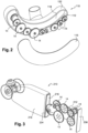
figure 2 est une vue schématique en perspective d'une deuxième réalisation d'un boitier selon l'invention ; et - La
figure 3 est une vue schématique en perspective d'une troisième réalisation d'un boitier selon l'invention. - Les
figures 1A, 1B et 1C représentent une première réalisation d'un boîtier de relais d'accessoires 10 d'une turbine à gaz de moteur d'avion selon l'invention, lafigure 1A étant une représentation globale du boîtier, lafigure 1B étant une représentation éclatée de certains de ses éléments constitutifs et lafigure 1C étant une représentation isolée d'un support 12 de roues dentées 14. On comprend que l'invention s'applique également aux turbines à gaz de moteurs d'hélicoptères, ainsi qu'aux groupes auxiliaires de puissance. - Ce boîtier 10 présente classiquement une forme générale de « banane » ou de « haricot » sensiblement parallélépipédique avec une face latérale avant 16 et une face latérale arrière 18 opposée à la face avant 16 et solidarisée avec celle-ci par l'intermédiaire du support 12 intercalée entre la face avant 16 et la face arrière 18. Pour réaliser cette solidarisation, la face avant 16 comprend une pluralité de perçages 20 formées sur sa périphérie et coopérant avec des perçages 22 de la périphérie du support 12 et des perçages 24 de la périphérie de la face arrière 18. On remarque que le support 12 comprend deux organes 26 d'accrochage chacun formé de deux chapes s'étendant à l'extérieur de l'enceinte délimitée par les faces avant 16 et arrière 18. Ces chapes permettent une fixation du boîtier 10 sur un carter de la turbomachine. Le boîtier 10 renferme un ou plusieurs trains (ou chaînes) d'engrenages formés par les roues dentées 14 engrenant ensemble qui s'étendent parallèlement aux faces latérales 16, 18 et qui ont classiquement pour fonction d'entraîner en rotation une pluralité d'accessoires (non représentés).
- Les accessoires sont montés chacun sur l'une des faces latérales 16, 18 du boîtier. Chaque accessoire comporte en outre un arbre d'alimentation (non représenté) qui est entrainé en rotation par coopération de formes, par exemple au moyen de cannelures, avec un arbre 28 portant une roue dentée pour y être entrainé (
figure 1C ). - Un arbre de transmission de puissance (non représenté) prélève de la puissance mécanique sur un arbre de la turbine (non représenté sur les figures) pour la transmettre aux différentes roues dentées 14 du train d'engrenages. A cet effet, l'arbre de transmission de puissance est couplé en rotation au train d'engrenage au moyen de l'une des roues dentées du train d'engrenages.
- Selon l'invention, chaque arbre 28 portant une roue dentée 14 est maintenu par un ou plusieurs paliers 30 à roulements qui sont tous portés par le support 12 intercalé latéralement entre les faces avant 16 et arrière 18 du boîtier 10. Le support 12 peut être constitué d'une platine de préférence métallique, avantageusement ajourée à la manière d'un treillis pour en limiter le poids.
- Dans cette réalisation, les faces avant 16 et arrière 18 forment des couvercles servant de support aux équipements. A cette fin, les couvercles comportent des fixations (non représentées) qui permettent de maintenir les accessoires/équipements, ces fixations peuvent être des taraudages, des goujons, des brides males en formes de V permettant de fixer l'équipement via un collier femelle également en V, ou tout autre moyen de fixation de l'équipement.
- Dans une seconde réalisation de l'invention représentée en
figure 2 , le boitier 110 comprend également une face avant 116 et une face arrière 118 qui sont reliées l'une à l'autre par un rebord périphérique 132 solidaire de la face arrière 118 qui vient s'appliquer et se fixer sur la face avant 116. Ainsi, les faces avant 116 et arrière 118 délimitent ensemble une enceinte logeant le support portant les roues dentées 14. Les accessoires sont fixés sur les faces avant et arrière d'une manière connue de l'état de la technique telle comme par exemple expliqué en relation avec la première réalisation. - Dans une troisième réalisation d'un boîtier 210 selon l'invention représenté en
figure 3 , les faces avant 216 et arrière 218 sont formées sur un carter monobloc comprenant une ouverture 234 de montage du support portant la chaine cinématique comprenant le ou les trains d'engrenages. Comme cela est visible, cette ouverture 234 peut être obturée par un organe obturateur 236. Cet organe obturateur peut éventuellement être monobloc avec la pièce 212. - Comme évoqué précédemment, l'invention permet de réduire l'épaisseur du boitier dans une direction perpendiculaire aux faces avant et arrière. Les faces avant et arrière sont également plus simples à concevoir puisqu'elle n'assure plus de maintien de la chaine cinématique et peuvent dès lors avoir des formes plus complexes et mieux adaptées à l'environnement dans lequel le boîtier est destiné à être monté.
- Dans les différentes réalisations de l'invention représentées aux figures, notons que le support peut comprendre des moyens de lubrification des paliers à roulements 28, ces moyens pouvant être par exemple un circuit d'huile intégré dans l'épaisseur du support 12, 112, 212 de manière à acheminer de l'huile jusqu'aux paliers. Il est ainsi possible de forer des canalisations dans le support 12, 112, 212 pour amener l'huile à différentes localisations du boîtier. Ces perçages peuvent être réalisés dans les bras structuraux qui composent le support. Il est encore possible de rapporter une canalisation sur le support 12, 112, 212.
Claims (9)
- Boîtier (10, 110, 210) de relais d'accessoires pour une turbomachine ayant une face latérale avant (16, 116, 216), une face latérale arrière (18, 118, 218) opposée à la face avant délimitant latéralement le boitier d'accessoires dans lequel est monté au moins un train d'engrenage composé de plusieurs roues dentées (14) engrenant ensemble, chaque roue dentée (14) étant portée par un arbre central (28), chaque arbre (28) étant guidé en rotation par des paliers (30) à roulements, caractérisé en ce que tous les paliers (30) à roulement sont portés par un même support (12, 112, 212) intercalé latéralement entre les faces avant (16, 116, 216) et arrière (18, 118, 218).
- Boîtier selon la revendication 1, dans lequel ledit support (12, 112, 212) est formé par une platine ajourée présentant une forme en treillis comportant une pluralité de logement de réception des paliers à roulements (30).
- Boîtier selon la revendication 1 ou 2, dans lequel le support (12, 112, 212) comprend des moyens de lubrification des paliers à roulements (30).
- Boîtier selon l'une des revendications 1 à 3, dans lequel le support (12, 112, 212) comprend des moyens d'accrochage (26) du boitier (10, 110, 210) sur un carter d'une turbine à gaz.
- Boîtier selon l'une des revendications 1 à 4, dans lequel au moins l'une de la face avant (16, 116, 216) et de la face arrière (18, 118, 218) supporte des équipements.
- Boîtier selon l'une des revendications 1 à 5, dans lequel les faces avant (116) et arrière (118) sont reliées l'une à l'autre par un rebord périphérique (132) formant avec lesdites faces avant et arrière une enceinte étanche.
- Boîtier selon l'une des revendications 1 à 5, dans lequel les faces avant (216) et arrière (218) sont formées sur un carter monobloc comprenant une ouverture (234) de montage dudit support (212).
- Boîtier selon la revendication 7, comprenant un obturateur (236) monobloc avec ledit support (212) et apte à obturer l'ouverture (234).
- Moteur à turbine à gaz d'avions ou d'hélicoptères, comprenant un boîtier d'accessoires selon l'une des revendications 1 à 8.
Applications Claiming Priority (2)
| Application Number | Priority Date | Filing Date | Title |
|---|---|---|---|
| FR1758259A FR3070726B1 (fr) | 2017-09-07 | 2017-09-07 | Boitier d'accessoires pour turbomachine |
| PCT/FR2018/052168 WO2019048778A1 (fr) | 2017-09-07 | 2018-09-05 | Boitier d'accessoires pour turbomachine |
Publications (2)
| Publication Number | Publication Date |
|---|---|
| EP3679233A1 EP3679233A1 (fr) | 2020-07-15 |
| EP3679233B1 true EP3679233B1 (fr) | 2024-10-30 |
Family
ID=60202189
Family Applications (1)
| Application Number | Title | Priority Date | Filing Date |
|---|---|---|---|
| EP18774097.2A Active EP3679233B1 (fr) | 2017-09-07 | 2018-09-05 | Boitier d'accessoires pour turbomachine |
Country Status (5)
| Country | Link |
|---|---|
| US (1) | US11795881B2 (fr) |
| EP (1) | EP3679233B1 (fr) |
| CN (1) | CN111051667B (fr) |
| FR (1) | FR3070726B1 (fr) |
| WO (1) | WO2019048778A1 (fr) |
Families Citing this family (1)
| Publication number | Priority date | Publication date | Assignee | Title |
|---|---|---|---|---|
| FR3107087B1 (fr) | 2020-02-10 | 2022-08-05 | Safran Trans Systems | Boîtier de relais d’accessoires pour une turbomachine |
Citations (1)
| Publication number | Priority date | Publication date | Assignee | Title |
|---|---|---|---|---|
| US2432358A (en) * | 1944-03-07 | 1947-12-09 | Gen Electric | Power plant |
Family Cites Families (15)
| Publication number | Priority date | Publication date | Assignee | Title |
|---|---|---|---|---|
| GB590419A (en) * | 1944-03-07 | 1947-07-17 | British Thomson Houston Co Ltd | Improvements in and relating to power plants |
| FR2928696B1 (fr) | 2008-03-14 | 2013-09-27 | Hispano Suiza Sa | Assemblage pour l'entrainement d'accessoires d'une turbine a gaz |
| FR2936273B1 (fr) * | 2008-09-22 | 2010-10-29 | Snecma | Procede et systeme de lubrification d'une turbomachine |
| FR2938015B1 (fr) * | 2008-11-05 | 2015-05-29 | Snecma | Attenuation des pics de couple sur un train d'engrenages dans une turbomachines |
| FR2941744B1 (fr) * | 2009-01-30 | 2011-09-16 | Hispano Suiza Sa | Ensemble d'un boitier de relais d'accessoires et d'un reservoir d'huile |
| FR2943264B1 (fr) * | 2009-03-17 | 2012-11-16 | Hispano Suiza Sa | Carter moule avec tuyauteries rapportees |
| US8347637B2 (en) * | 2010-05-25 | 2013-01-08 | United Technologies Corporation | Accessory gearbox with internal layshaft |
| US20120006137A1 (en) * | 2010-07-07 | 2012-01-12 | Hamilton Sundstrand Corporation | Gear driven accessory for gearbox |
| US10060345B2 (en) * | 2011-02-23 | 2018-08-28 | Achates Power, Inc. | Dual crankshaft, opposed-piston engine constructions |
| FR2977280B1 (fr) * | 2011-06-28 | 2015-04-10 | Hispano Suiza Sa | Boitier perfectionne de relais d'accessoires d'une turbine a gaz |
| WO2014112988A1 (fr) * | 2013-01-16 | 2014-07-24 | United Technologies Corporation | Écran thermique pour réducteur de moteur à turbine à gaz |
| FR3017658B1 (fr) * | 2014-02-18 | 2019-04-12 | Safran Transmission Systems | Boitier d'entrainement d'equipements pour turbomachine |
| FR3018860B1 (fr) * | 2014-03-21 | 2021-10-15 | Hispano Suiza Sa | Relais d'accessoires pour moteur a turbine a gaz |
| US9605562B2 (en) * | 2015-02-09 | 2017-03-28 | United Techologies Corporation | Turbomachine accessory gearbox alignment pin |
| US10072582B2 (en) * | 2016-04-28 | 2018-09-11 | General Electric Company | Integral offset oil tank for inline accessory gearbox |
-
2017
- 2017-09-07 FR FR1758259A patent/FR3070726B1/fr active Active
-
2018
- 2018-09-05 US US16/644,997 patent/US11795881B2/en active Active
- 2018-09-05 CN CN201880055494.XA patent/CN111051667B/zh active Active
- 2018-09-05 EP EP18774097.2A patent/EP3679233B1/fr active Active
- 2018-09-05 WO PCT/FR2018/052168 patent/WO2019048778A1/fr not_active Ceased
Patent Citations (1)
| Publication number | Priority date | Publication date | Assignee | Title |
|---|---|---|---|---|
| US2432358A (en) * | 1944-03-07 | 1947-12-09 | Gen Electric | Power plant |
Also Published As
| Publication number | Publication date |
|---|---|
| FR3070726B1 (fr) | 2019-08-23 |
| WO2019048778A1 (fr) | 2019-03-14 |
| CN111051667B (zh) | 2024-02-27 |
| EP3679233A1 (fr) | 2020-07-15 |
| CN111051667A (zh) | 2020-04-21 |
| FR3070726A1 (fr) | 2019-03-08 |
| US11795881B2 (en) | 2023-10-24 |
| US20200200092A1 (en) | 2020-06-25 |
Similar Documents
| Publication | Publication Date | Title |
|---|---|---|
| CA2938385C (fr) | Turbomachine equipee d'un groupe de lubrification | |
| EP3137741B1 (fr) | Turbomachine d'aéronef a prélèvement de puissance mécanique amélioré | |
| CA2947249C (fr) | Assemblage pour turbomachine d'aeronef et son procede de montage | |
| EP2726713A1 (fr) | Boitier perfectionne de relais d'accessoires d'une turbine a gaz | |
| EP3956555B1 (fr) | Reducteur de vitesse d'une turbomachine | |
| EP3682139B1 (fr) | Pivot pour palier lisse | |
| EP3999729B1 (fr) | Réducteur à train épicycloïdal pour une turbomachine | |
| EP3679233B1 (fr) | Boitier d'accessoires pour turbomachine | |
| CA2981171C (fr) | Turbomoteur encastrable dans un boitier reducteur | |
| EP3715607B1 (fr) | Pignon d entrainement d'au moins un arbre d'accessoire pour un boitier d'accessoires de turbomachine d'aeronef | |
| EP2723995B1 (fr) | Relais d'accessoires à durée de vie ameliorée | |
| EP3601747B1 (fr) | Relais d'accessoires pour moteur a turbine a gaz | |
| EP3997317B1 (fr) | Assemblage de maintien d'un train d'engrenages dans une turbomachine | |
| EP3755894B1 (fr) | Assemblage de maintien d'un train d'engrenages dans une turbomachine | |
| EP3907391B1 (fr) | Relais d'accessoires | |
| EP3736428A1 (fr) | Gorge de joint rapportée pour accouplement par cannelures | |
| EP3810911A1 (fr) | Turbomachine d'aeronef a au moins deux corps et prelevement de puissance |
Legal Events
| Date | Code | Title | Description |
|---|---|---|---|
| STAA | Information on the status of an ep patent application or granted ep patent |
Free format text: STATUS: UNKNOWN |
|
| STAA | Information on the status of an ep patent application or granted ep patent |
Free format text: STATUS: THE INTERNATIONAL PUBLICATION HAS BEEN MADE |
|
| PUAI | Public reference made under article 153(3) epc to a published international application that has entered the european phase |
Free format text: ORIGINAL CODE: 0009012 |
|
| STAA | Information on the status of an ep patent application or granted ep patent |
Free format text: STATUS: REQUEST FOR EXAMINATION WAS MADE |
|
| 17P | Request for examination filed |
Effective date: 20200303 |
|
| AK | Designated contracting states |
Kind code of ref document: A1 Designated state(s): AL AT BE BG CH CY CZ DE DK EE ES FI FR GB GR HR HU IE IS IT LI LT LU LV MC MK MT NL NO PL PT RO RS SE SI SK SM TR |
|
| AX | Request for extension of the european patent |
Extension state: BA ME |
|
| DAV | Request for validation of the european patent (deleted) | ||
| DAX | Request for extension of the european patent (deleted) | ||
| STAA | Information on the status of an ep patent application or granted ep patent |
Free format text: STATUS: EXAMINATION IS IN PROGRESS |
|
| 17Q | First examination report despatched |
Effective date: 20220428 |
|
| GRAP | Despatch of communication of intention to grant a patent |
Free format text: ORIGINAL CODE: EPIDOSNIGR1 |
|
| STAA | Information on the status of an ep patent application or granted ep patent |
Free format text: STATUS: GRANT OF PATENT IS INTENDED |
|
| INTG | Intention to grant announced |
Effective date: 20240801 |
|
| GRAS | Grant fee paid |
Free format text: ORIGINAL CODE: EPIDOSNIGR3 |
|
| GRAA | (expected) grant |
Free format text: ORIGINAL CODE: 0009210 |
|
| STAA | Information on the status of an ep patent application or granted ep patent |
Free format text: STATUS: THE PATENT HAS BEEN GRANTED |
|
| AK | Designated contracting states |
Kind code of ref document: B1 Designated state(s): AL AT BE BG CH CY CZ DE DK EE ES FI FR GB GR HR HU IE IS IT LI LT LU LV MC MK MT NL NO PL PT RO RS SE SI SK SM TR |
|
| REG | Reference to a national code |
Ref country code: GB Ref legal event code: FG4D Free format text: NOT ENGLISH |
|
| REG | Reference to a national code |
Ref country code: CH Ref legal event code: EP |
|
| REG | Reference to a national code |
Ref country code: IE Ref legal event code: FG4D Free format text: LANGUAGE OF EP DOCUMENT: FRENCH |
|
| REG | Reference to a national code |
Ref country code: DE Ref legal event code: R096 Ref document number: 602018076007 Country of ref document: DE |
|
| REG | Reference to a national code |
Ref country code: LT Ref legal event code: MG9D |
|
| REG | Reference to a national code |
Ref country code: NL Ref legal event code: MP Effective date: 20241030 |
|
| PG25 | Lapsed in a contracting state [announced via postgrant information from national office to epo] |
Ref country code: HR Free format text: LAPSE BECAUSE OF FAILURE TO SUBMIT A TRANSLATION OF THE DESCRIPTION OR TO PAY THE FEE WITHIN THE PRESCRIBED TIME-LIMIT Effective date: 20241030 Ref country code: IS Free format text: LAPSE BECAUSE OF FAILURE TO SUBMIT A TRANSLATION OF THE DESCRIPTION OR TO PAY THE FEE WITHIN THE PRESCRIBED TIME-LIMIT Effective date: 20250228 Ref country code: PT Free format text: LAPSE BECAUSE OF FAILURE TO SUBMIT A TRANSLATION OF THE DESCRIPTION OR TO PAY THE FEE WITHIN THE PRESCRIBED TIME-LIMIT Effective date: 20250228 |
|
| PG25 | Lapsed in a contracting state [announced via postgrant information from national office to epo] |
Ref country code: NL Free format text: LAPSE BECAUSE OF FAILURE TO SUBMIT A TRANSLATION OF THE DESCRIPTION OR TO PAY THE FEE WITHIN THE PRESCRIBED TIME-LIMIT Effective date: 20241030 Ref country code: FI Free format text: LAPSE BECAUSE OF FAILURE TO SUBMIT A TRANSLATION OF THE DESCRIPTION OR TO PAY THE FEE WITHIN THE PRESCRIBED TIME-LIMIT Effective date: 20241030 |
|
| REG | Reference to a national code |
Ref country code: AT Ref legal event code: MK05 Ref document number: 1737068 Country of ref document: AT Kind code of ref document: T Effective date: 20241030 |
|
| PG25 | Lapsed in a contracting state [announced via postgrant information from national office to epo] |
Ref country code: BG Free format text: LAPSE BECAUSE OF FAILURE TO SUBMIT A TRANSLATION OF THE DESCRIPTION OR TO PAY THE FEE WITHIN THE PRESCRIBED TIME-LIMIT Effective date: 20241030 |
|
| PG25 | Lapsed in a contracting state [announced via postgrant information from national office to epo] |
Ref country code: ES Free format text: LAPSE BECAUSE OF FAILURE TO SUBMIT A TRANSLATION OF THE DESCRIPTION OR TO PAY THE FEE WITHIN THE PRESCRIBED TIME-LIMIT Effective date: 20241030 |
|
| PG25 | Lapsed in a contracting state [announced via postgrant information from national office to epo] |
Ref country code: NO Free format text: LAPSE BECAUSE OF FAILURE TO SUBMIT A TRANSLATION OF THE DESCRIPTION OR TO PAY THE FEE WITHIN THE PRESCRIBED TIME-LIMIT Effective date: 20250130 |
|
| PG25 | Lapsed in a contracting state [announced via postgrant information from national office to epo] |
Ref country code: LV Free format text: LAPSE BECAUSE OF FAILURE TO SUBMIT A TRANSLATION OF THE DESCRIPTION OR TO PAY THE FEE WITHIN THE PRESCRIBED TIME-LIMIT Effective date: 20241030 Ref country code: GR Free format text: LAPSE BECAUSE OF FAILURE TO SUBMIT A TRANSLATION OF THE DESCRIPTION OR TO PAY THE FEE WITHIN THE PRESCRIBED TIME-LIMIT Effective date: 20250131 Ref country code: AT Free format text: LAPSE BECAUSE OF FAILURE TO SUBMIT A TRANSLATION OF THE DESCRIPTION OR TO PAY THE FEE WITHIN THE PRESCRIBED TIME-LIMIT Effective date: 20241030 |
|
| PG25 | Lapsed in a contracting state [announced via postgrant information from national office to epo] |
Ref country code: PL Free format text: LAPSE BECAUSE OF FAILURE TO SUBMIT A TRANSLATION OF THE DESCRIPTION OR TO PAY THE FEE WITHIN THE PRESCRIBED TIME-LIMIT Effective date: 20241030 |
|
| PG25 | Lapsed in a contracting state [announced via postgrant information from national office to epo] |
Ref country code: RS Free format text: LAPSE BECAUSE OF FAILURE TO SUBMIT A TRANSLATION OF THE DESCRIPTION OR TO PAY THE FEE WITHIN THE PRESCRIBED TIME-LIMIT Effective date: 20250130 |
|
| PG25 | Lapsed in a contracting state [announced via postgrant information from national office to epo] |
Ref country code: SM Free format text: LAPSE BECAUSE OF FAILURE TO SUBMIT A TRANSLATION OF THE DESCRIPTION OR TO PAY THE FEE WITHIN THE PRESCRIBED TIME-LIMIT Effective date: 20241030 |
|
| PG25 | Lapsed in a contracting state [announced via postgrant information from national office to epo] |
Ref country code: DK Free format text: LAPSE BECAUSE OF FAILURE TO SUBMIT A TRANSLATION OF THE DESCRIPTION OR TO PAY THE FEE WITHIN THE PRESCRIBED TIME-LIMIT Effective date: 20241030 |
|
| PG25 | Lapsed in a contracting state [announced via postgrant information from national office to epo] |
Ref country code: EE Free format text: LAPSE BECAUSE OF FAILURE TO SUBMIT A TRANSLATION OF THE DESCRIPTION OR TO PAY THE FEE WITHIN THE PRESCRIBED TIME-LIMIT Effective date: 20241030 |
|
| PG25 | Lapsed in a contracting state [announced via postgrant information from national office to epo] |
Ref country code: RO Free format text: LAPSE BECAUSE OF FAILURE TO SUBMIT A TRANSLATION OF THE DESCRIPTION OR TO PAY THE FEE WITHIN THE PRESCRIBED TIME-LIMIT Effective date: 20241030 |
|
| PG25 | Lapsed in a contracting state [announced via postgrant information from national office to epo] |
Ref country code: SK Free format text: LAPSE BECAUSE OF FAILURE TO SUBMIT A TRANSLATION OF THE DESCRIPTION OR TO PAY THE FEE WITHIN THE PRESCRIBED TIME-LIMIT Effective date: 20241030 |
|
| PG25 | Lapsed in a contracting state [announced via postgrant information from national office to epo] |
Ref country code: CZ Free format text: LAPSE BECAUSE OF FAILURE TO SUBMIT A TRANSLATION OF THE DESCRIPTION OR TO PAY THE FEE WITHIN THE PRESCRIBED TIME-LIMIT Effective date: 20241030 |
|
| PG25 | Lapsed in a contracting state [announced via postgrant information from national office to epo] |
Ref country code: IT Free format text: LAPSE BECAUSE OF FAILURE TO SUBMIT A TRANSLATION OF THE DESCRIPTION OR TO PAY THE FEE WITHIN THE PRESCRIBED TIME-LIMIT Effective date: 20241030 |
|
| REG | Reference to a national code |
Ref country code: DE Ref legal event code: R097 Ref document number: 602018076007 Country of ref document: DE |
|
| PLBE | No opposition filed within time limit |
Free format text: ORIGINAL CODE: 0009261 |
|
| STAA | Information on the status of an ep patent application or granted ep patent |
Free format text: STATUS: NO OPPOSITION FILED WITHIN TIME LIMIT |
|
| PG25 | Lapsed in a contracting state [announced via postgrant information from national office to epo] |
Ref country code: SE Free format text: LAPSE BECAUSE OF FAILURE TO SUBMIT A TRANSLATION OF THE DESCRIPTION OR TO PAY THE FEE WITHIN THE PRESCRIBED TIME-LIMIT Effective date: 20241030 |
|
| 26N | No opposition filed |
Effective date: 20250731 |
|
| PGFP | Annual fee paid to national office [announced via postgrant information from national office to epo] |
Ref country code: DE Payment date: 20250919 Year of fee payment: 8 |
|
| PGFP | Annual fee paid to national office [announced via postgrant information from national office to epo] |
Ref country code: GB Payment date: 20250923 Year of fee payment: 8 |
|
| PGFP | Annual fee paid to national office [announced via postgrant information from national office to epo] |
Ref country code: FR Payment date: 20250923 Year of fee payment: 8 |