EP3678589B1 - Intraluminales gefässprothesensystem - Google Patents
Intraluminales gefässprothesensystem Download PDFInfo
- Publication number
- EP3678589B1 EP3678589B1 EP18773947.9A EP18773947A EP3678589B1 EP 3678589 B1 EP3678589 B1 EP 3678589B1 EP 18773947 A EP18773947 A EP 18773947A EP 3678589 B1 EP3678589 B1 EP 3678589B1
- Authority
- EP
- European Patent Office
- Prior art keywords
- prosthesis
- vascular prosthesis
- vessel prosthesis
- lumen
- anchoring
- Prior art date
- Legal status (The legal status is an assumption and is not a legal conclusion. Google has not performed a legal analysis and makes no representation as to the accuracy of the status listed.)
- Active
Links
Images


Classifications
-
- A—HUMAN NECESSITIES
- A61—MEDICAL OR VETERINARY SCIENCE; HYGIENE
- A61F—FILTERS IMPLANTABLE INTO BLOOD VESSELS; PROSTHESES; DEVICES PROVIDING PATENCY TO, OR PREVENTING COLLAPSING OF, TUBULAR STRUCTURES OF THE BODY, e.g. STENTS; ORTHOPAEDIC, NURSING OR CONTRACEPTIVE DEVICES; FOMENTATION; TREATMENT OR PROTECTION OF EYES OR EARS; BANDAGES, DRESSINGS OR ABSORBENT PADS; FIRST-AID KITS
- A61F2/00—Filters implantable into blood vessels; Prostheses, i.e. artificial substitutes or replacements for parts of the body; Appliances for connecting them with the body; Devices providing patency to, or preventing collapsing of, tubular structures of the body, e.g. stents
- A61F2/02—Prostheses implantable into the body
- A61F2/04—Hollow or tubular parts of organs, e.g. bladders, tracheae, bronchi or bile ducts
- A61F2/06—Blood vessels
- A61F2/07—Stent-grafts
-
- A—HUMAN NECESSITIES
- A61—MEDICAL OR VETERINARY SCIENCE; HYGIENE
- A61F—FILTERS IMPLANTABLE INTO BLOOD VESSELS; PROSTHESES; DEVICES PROVIDING PATENCY TO, OR PREVENTING COLLAPSING OF, TUBULAR STRUCTURES OF THE BODY, e.g. STENTS; ORTHOPAEDIC, NURSING OR CONTRACEPTIVE DEVICES; FOMENTATION; TREATMENT OR PROTECTION OF EYES OR EARS; BANDAGES, DRESSINGS OR ABSORBENT PADS; FIRST-AID KITS
- A61F2/00—Filters implantable into blood vessels; Prostheses, i.e. artificial substitutes or replacements for parts of the body; Appliances for connecting them with the body; Devices providing patency to, or preventing collapsing of, tubular structures of the body, e.g. stents
- A61F2/82—Devices providing patency to, or preventing collapsing of, tubular structures of the body, e.g. stents
- A61F2/86—Stents in a form characterised by the wire-like elements; Stents in the form characterised by a net-like or mesh-like structure
-
- A—HUMAN NECESSITIES
- A61—MEDICAL OR VETERINARY SCIENCE; HYGIENE
- A61F—FILTERS IMPLANTABLE INTO BLOOD VESSELS; PROSTHESES; DEVICES PROVIDING PATENCY TO, OR PREVENTING COLLAPSING OF, TUBULAR STRUCTURES OF THE BODY, e.g. STENTS; ORTHOPAEDIC, NURSING OR CONTRACEPTIVE DEVICES; FOMENTATION; TREATMENT OR PROTECTION OF EYES OR EARS; BANDAGES, DRESSINGS OR ABSORBENT PADS; FIRST-AID KITS
- A61F2/00—Filters implantable into blood vessels; Prostheses, i.e. artificial substitutes or replacements for parts of the body; Appliances for connecting them with the body; Devices providing patency to, or preventing collapsing of, tubular structures of the body, e.g. stents
- A61F2/82—Devices providing patency to, or preventing collapsing of, tubular structures of the body, e.g. stents
- A61F2/852—Two or more distinct overlapping stents
-
- A—HUMAN NECESSITIES
- A61—MEDICAL OR VETERINARY SCIENCE; HYGIENE
- A61F—FILTERS IMPLANTABLE INTO BLOOD VESSELS; PROSTHESES; DEVICES PROVIDING PATENCY TO, OR PREVENTING COLLAPSING OF, TUBULAR STRUCTURES OF THE BODY, e.g. STENTS; ORTHOPAEDIC, NURSING OR CONTRACEPTIVE DEVICES; FOMENTATION; TREATMENT OR PROTECTION OF EYES OR EARS; BANDAGES, DRESSINGS OR ABSORBENT PADS; FIRST-AID KITS
- A61F2/00—Filters implantable into blood vessels; Prostheses, i.e. artificial substitutes or replacements for parts of the body; Appliances for connecting them with the body; Devices providing patency to, or preventing collapsing of, tubular structures of the body, e.g. stents
- A61F2/82—Devices providing patency to, or preventing collapsing of, tubular structures of the body, e.g. stents
- A61F2/86—Stents in a form characterised by the wire-like elements; Stents in the form characterised by a net-like or mesh-like structure
- A61F2/89—Stents in a form characterised by the wire-like elements; Stents in the form characterised by a net-like or mesh-like structure the wire-like elements comprising two or more adjacent rings flexibly connected by separate members
-
- A—HUMAN NECESSITIES
- A61—MEDICAL OR VETERINARY SCIENCE; HYGIENE
- A61F—FILTERS IMPLANTABLE INTO BLOOD VESSELS; PROSTHESES; DEVICES PROVIDING PATENCY TO, OR PREVENTING COLLAPSING OF, TUBULAR STRUCTURES OF THE BODY, e.g. STENTS; ORTHOPAEDIC, NURSING OR CONTRACEPTIVE DEVICES; FOMENTATION; TREATMENT OR PROTECTION OF EYES OR EARS; BANDAGES, DRESSINGS OR ABSORBENT PADS; FIRST-AID KITS
- A61F2/00—Filters implantable into blood vessels; Prostheses, i.e. artificial substitutes or replacements for parts of the body; Appliances for connecting them with the body; Devices providing patency to, or preventing collapsing of, tubular structures of the body, e.g. stents
- A61F2/02—Prostheses implantable into the body
- A61F2/04—Hollow or tubular parts of organs, e.g. bladders, tracheae, bronchi or bile ducts
- A61F2/06—Blood vessels
- A61F2002/061—Blood vessels provided with means for allowing access to secondary lumens
-
- A—HUMAN NECESSITIES
- A61—MEDICAL OR VETERINARY SCIENCE; HYGIENE
- A61F—FILTERS IMPLANTABLE INTO BLOOD VESSELS; PROSTHESES; DEVICES PROVIDING PATENCY TO, OR PREVENTING COLLAPSING OF, TUBULAR STRUCTURES OF THE BODY, e.g. STENTS; ORTHOPAEDIC, NURSING OR CONTRACEPTIVE DEVICES; FOMENTATION; TREATMENT OR PROTECTION OF EYES OR EARS; BANDAGES, DRESSINGS OR ABSORBENT PADS; FIRST-AID KITS
- A61F2230/00—Geometry of prostheses classified in groups A61F2/00 - A61F2/26 or A61F2/82 or A61F9/00 or A61F11/00 or subgroups thereof
- A61F2230/0063—Three-dimensional shapes
- A61F2230/0067—Three-dimensional shapes conical
-
- A—HUMAN NECESSITIES
- A61—MEDICAL OR VETERINARY SCIENCE; HYGIENE
- A61F—FILTERS IMPLANTABLE INTO BLOOD VESSELS; PROSTHESES; DEVICES PROVIDING PATENCY TO, OR PREVENTING COLLAPSING OF, TUBULAR STRUCTURES OF THE BODY, e.g. STENTS; ORTHOPAEDIC, NURSING OR CONTRACEPTIVE DEVICES; FOMENTATION; TREATMENT OR PROTECTION OF EYES OR EARS; BANDAGES, DRESSINGS OR ABSORBENT PADS; FIRST-AID KITS
- A61F2250/00—Special features of prostheses classified in groups A61F2/00 - A61F2/26 or A61F2/82 or A61F9/00 or A61F11/00 or subgroups thereof
- A61F2250/0058—Additional features; Implant or prostheses properties not otherwise provided for
- A61F2250/006—Additional features; Implant or prostheses properties not otherwise provided for modular
- A61F2250/0063—Nested prosthetic parts
-
- A—HUMAN NECESSITIES
- A61—MEDICAL OR VETERINARY SCIENCE; HYGIENE
- A61F—FILTERS IMPLANTABLE INTO BLOOD VESSELS; PROSTHESES; DEVICES PROVIDING PATENCY TO, OR PREVENTING COLLAPSING OF, TUBULAR STRUCTURES OF THE BODY, e.g. STENTS; ORTHOPAEDIC, NURSING OR CONTRACEPTIVE DEVICES; FOMENTATION; TREATMENT OR PROTECTION OF EYES OR EARS; BANDAGES, DRESSINGS OR ABSORBENT PADS; FIRST-AID KITS
- A61F2250/00—Special features of prostheses classified in groups A61F2/00 - A61F2/26 or A61F2/82 or A61F9/00 or A61F11/00 or subgroups thereof
- A61F2250/0058—Additional features; Implant or prostheses properties not otherwise provided for
- A61F2250/006—Additional features; Implant or prostheses properties not otherwise provided for modular
- A61F2250/0064—Sets comprising a plurality of prosthetic parts of different sizes
Definitions
- the present invention relates to an intraluminal vascular prosthesis and an intraluminal vascular prosthesis system for implantation in the region of the aortic arch of a patient.
- Such vascular implants are known in the state of the art, for example from DE 103 37 739.5 known.
- intraluminal vascular prostheses also known as endovascular vascular stents/stent grafts
- endovascular vascular stents/stent grafts are used to treat weakened, injured, ruptured or aneurysmal vessels.
- a vascular prosthesis or stent graft is released at the diseased or injured part of the vessel, which restores the functionality of the original vessel or supports the remaining vascular integrity.
- An aneurysm is an expansion or bulging of an arterial blood vessel as a result of congenital or acquired changes in the wall.
- the bulging can affect the entire vessel wall or, as in the case of a false aneurysm or dissection, blood can leak from the lumen of the vessel between the layers of the vessel wall and shear them apart. If an aneurysm is not treated in an advanced stage, the artery can rupture, resulting in the patient bleeding to death internally.
- the self-expanding vascular implants used to treat such aneurysms generally consist of a hollow cylindrical metal frame or scaffold, the outer surface of which is covered with a textile or polymer film, resulting in a hollow cylindrical body.
- the vascular prosthesis is compressed radially so that its cross-sectional area is significantly reduced. reduced.
- the vascular prosthesis is then brought into the area of the aneurysm using an introduction system, where it is released. Due to the spring effect of the metal frame/scaffold, the vascular prosthesis expands back to its original shape and stretches its outer surface, which clamps itself inside the blood vessel proximal and distal to the aneurysm. In this way, the blood now flows through the vascular prosthesis and further stress on the bulge is prevented.
- the metal frame of such vascular prostheses usually consists of a wire mesh or of so-called stent springs arranged one behind the other in a meandering shape, which may be connected to one another via wire connecting supports, or which are only connected to one another via the prosthesis material.
- the wire mesh or the stent springs are usually made of a shape-memory material, usually nitinol, which means that the stent springs return to the expanded state after being introduced into a vessel for release and thus "stretch" the vascular implant.
- aneurysms often occur in the abdominal artery (aorta abdominalis ) or thoracic artery ( aorta thoracica ).
- abdominal artery aorta abdominalis
- thoracic artery aorta thoracica
- Aneurysms can also occur in the so-called ascending branch of the aorta ( aorta ascendens ).
- the ascending branch of the aorta is directly connected to the heart. Starting from the aortic root ( sinus aortae ), the ascending branch runs upwards away from the heart in a slightly curved shape and then passes into the aortic arch ( arcus aortae ) and leads into the descending branch of the aorta (aorta descendens ).
- the head vessels branch off in the area of the aortic arch, including the left and right carotid arteries.
- the aortic arch has a curve of around 180° with a very tight radius and connects the ascending branch of the aorta with the thoracic artery and then with the abdominal artery.
- Vascular diseases such as aneurysms or dissections in the area of the aortic arch are usually treated in an invasive open procedure.
- Such an operation usually requires two large, separate operations and is a very large, complex and therefore dangerous procedure, since not only the heart, but also the patient's brain and abdominal organs must be subjected to hypothermic perfusion, i.e. artificial, cold extracorporeal blood flow, or hypothermic circulatory arrest.
- hypothermic perfusion i.e. artificial, cold extracorporeal blood flow, or hypothermic circulatory arrest.
- only a few cardiac surgeons at experienced centers are familiar with such an operation.
- vascular prosthesis is known in which vascular prosthesis side branches can be anchored in the lumen of the vascular prosthesis via an opening provided in the prosthesis wall, which in turn is provided in a recess in the wall.
- vascular prosthesis side branches can be anchored in the lumen of the vascular prosthesis via an opening provided in the prosthesis wall, which in turn is provided in a recess in the wall.
- WO 2013/155306 A Branching double-lumen vascular prostheses are also known.
- stents and stent grafts or combinations of stents that are inserted minimally invasively are currently known. However, these are only of limited use in many patients with diseased vessels.
- the object of the present invention is therefore to provide a vascular prosthesis and a vascular prosthesis system with which the area of the ascending aorta, the aortic arch and the descending aorta of a large number of different patients with different vascular properties can be treated quickly and easily, or which also enables the above-described interventions to be carried out by less experienced cardiac surgeons.
- an intraluminal vascular prosthesis system for implantation in the region of the aortic arch of a patient which has at least the following: a hollow cylindrical main vascular prosthesis, which has a lumen guided through the main vascular prosthesis, a first lumen end, a second lumen end, a hollow cylindrical stent framework, optionally with a prosthesis material attached thereto, a length L1 and a diameter D1, wherein the hollow cylindrical main vascular prosthesis is designed and dimensioned for implantation in the region of the aortic arch and the descending aorta of the patient, and wherein the main vascular prosthesis has at least one hollow cylindrical anchoring vascular prosthesis, which has a lumen guided through the anchoring vascular prosthesis, a first lumen end, a second lumen end, a hollow cylindrical stent framework, optionally with a prosthesis material attached thereto attached prosthetic material, has a length L2 and a diameter D2, wherein
- the intraluminal vascular prosthesis system according to the invention for implantation in the region of the aortic arch further comprises at least one hollow cylindrical lateral vascular prosthesis, a lumen guided through the lateral vascular prosthesis which has a first lumen end, a second lumen end, a hollow cylindrical stent frame, optionally with a prosthetic material attached thereto, a length L3 and a diameter D3, wherein the hollow cylindrical lateral vascular prosthesis is designed for implantation to bridge the branch of the subclavian artery or the carotid artery of the patient is designed and dimensioned in such a way that the lateral vascular prosthesis can be positioned with its first lumen end in the subclavian artery or the carotid artery , and with its second lumen end for secure anchoring of the lateral vascular prosthesis can be at least partially introduced into the lumen of the anchoring vascular prosthesis via the first lumen end of the anchoring vascular prosthesis and fixed therein.
- the new vascular prosthesis or the new vascular prosthesis system makes it possible to treat a weakened, injured, torn or aneurysmal vessel, particularly in the area of the aortic arch, in a simple manner.
- a vascular prosthesis is thus provided which makes it possible to simplify surgical interventions, particularly on the aortic arch, or in the ascending aorta, the aortic arch and the descending aorta, and to significantly shorten them in time.
- the vascular prosthesis or vascular prosthesis system according to the invention can be used to treat vessels that have side vessels branching off in the area to be treated. Due to the special structure, the side vessels can continue to be supplied with blood via at least one side vascular prosthesis, while at the same time the injured vessels supported by the intraluminal vascular prosthesis.
- the introduction and placement of this system can be handled precisely and easily due to its at least two-part structure, consisting of a hollow cylindrical main vascular prosthesis together with the anchoring vascular prosthesis and the side vascular prosthesis.
- the intraluminal vascular prosthesis is first implanted at the desired location in the vessel, preferably the aortic arch.
- a lateral vascular prosthesis is then implanted into the lateral vessel, with the first lumen end being positioned in the lateral vessel, while the second lumen end can be at least partially inserted into the lumen of the anchoring vascular prosthesis via the first lumen end of the anchoring vascular prosthesis to securely anchor the lateral vascular prosthesis and can be fixed therein.
- the vascular prosthesis and the lateral vascular prosthesis can be implanted separately from one another.
- the vascular prosthesis according to the invention and the vascular prosthesis system according to the invention therefore offer the advantage that not only highly specialized heart surgeons can perform the above-described interventions on the aortic arch, but also inexperienced specialists.
- the invention also offers the advantage that the vascular prosthesis and the vascular prosthesis system can be adapted to the respective anatomical conditions of the patient to be treated.
- the lateral vascular prosthesis is at least partially anchored or "inserted" into the anchoring vascular prosthesis, very anatomically different vessels can be treated with the same vascular prosthesis system. This can be achieved by the different insertion/anchoring depth of the lateral vascular prosthesis in the anchoring vascular prosthesis. If the lateral vessels are further away from the actual main vascular prosthesis, the insertion depth can be selected to be lower, in contrast to a greater anchoring depth for lateral vessels that are close by.
- the implantation of the vascular prosthesis system is particularly simplified because the main vascular prosthesis does not have to be precisely aligned in relation to the branching side vessels.
- the alignment can be corrected by the "anchoring system" according to the invention and the associated respective insertion/anchoring depth of the side vascular prosthesis in the anchoring vascular prosthesis.
- the alignment of a one-piece vascular prosthesis with branching side vessels known from the prior art not only complicates the implantation, but also the manufacture of such implants.
- the main vascular prosthesis, the at least one anchoring vascular prosthesis and the at least one side vascular prosthesis can be present as a covered or uncovered stent; i.e., they can be at least partially covered with a prosthetic material, or have a prosthetic material attached to the stent framework.
- a prosthetic material e.g., a prosthetic material that is at least partially covered with a prosthetic material, or have a prosthetic material attached to the stent framework.
- the main vascular prosthesis if it has a prosthetic material, has a fenestration region, i.e. a region via which the side vascular prosthesis can be at least partially introduced and anchored in the lumen of the anchoring vascular prosthesis present in the lumen of the main vascular prosthesis.
- This fenestration region can be selected, for example, from fenestration regions in the prosthetic material, individual openings in the jacket region of the main vascular prosthesis, or an open region that extends circumferentially over the entire circumference of the main vascular prosthesis in this region.
- the side vascular prosthesis can be at least partially introduced and anchored via the first lumen end of the main vascular prosthesis into the lumen of the anchoring vascular prosthesis present in the lumen of the main vascular prosthesis.
- the main vascular prosthesis can further comprise at least two stent framework sections or consist of at least two stent framework sections that can be connected to one another, for example by partially inserting the second stent framework section into the second stent framework section.
- the vascular prosthesis has several anchoring vascular prostheses.
- the number of anchoring vascular prostheses depends primarily on the number of outgoing side vessels that are to be treated by the side vascular prostheses.
- the first lumen end of the main vascular prosthesis and the first lumen end of the anchoring vascular prosthesis are arranged flush.
- “flush” means that the anchoring vascular prosthesis is aligned with its first lumen end at the first lumen end of the main vascular prosthesis and thus both lumen ends end on the same level, so to speak.
- the anchoring vascular prosthesis extends from the first lumen end of the main vascular prosthesis in the lumen of the main vascular prosthesis in the direction of the second lumen end along the inner wall of the main vascular prosthesis. Access to the anchoring vascular prosthesis for a side vascular prosthesis therefore does not take place via a side wall or a fenestration in the main vascular prosthesis, but via the first lumen end of the main vascular prosthesis.
- distal and proximal are used for stent grafts or endoluminal prostheses, as well as in this case, to refer to the respective ends, whereby the term “distal” refers to the part or end that is further downstream in relation to the blood flow.
- proximal refers to a part or end that is further upstream in relation to the blood flow.
- distal means in the direction of the blood flow
- proximal means opposite to the direction of the blood flow.
- distal refers to the end of the catheter or delivery system that is inserted into the patient, or that is furthest away from the user, and the term “proximal” refers to the end that is closer to the user.
- the "proximal" and “distal” openings of the vascular implant are the openings through which the blood flow through the hollow cylindrical lumen of the vascular implant is ensured: If the vascular implant according to the invention is implanted in a blood vessel such as the aorta, the blood coming from the heart flows through the proximal opening of the vascular implant and leaves the vascular implant through its distal openings.
- the hollow cylindrical main vascular prosthesis or its anchoring vascular prosthesis, as well as the side vascular prosthesis can have a uniform diameter over their entire length, or different diameters.
- the hollow cylindrical stent framework is a metal frame, which is usually made of a wire mesh or of so-called stent springs arranged one behind the other in a meandering shape, which may be connected to one another via wire connecting supports, or which are only connected to one another via the prosthesis material.
- the wire mesh or the stent springs are usually made of shape memory material, usually nitinol, which means that the stent springs return to the expanded state after implantation in a vessel for release, thereby "stretching" the vascular prosthesis.
- the main vascular prosthesis and/or the anchoring vascular prosthesis and/or the side vascular prosthesis has/have a stent framework and a prosthetic material attached thereto.
- prosthetic framework means any metal framework that provides an expansion force to keep a vessel open by stretching or expanding the framework of a vascular prosthesis, possibly in combination with a prosthetic material attached to the framework.
- the prosthetic material preferably consists of a biocompatible material, which means that the contact between the vascular implant and the vessel wall is free of complications.
- the prosthetic material comprises a material that is selected from a textile or a polymer.
- the prosthetic material comprises or is formed from a material that is selected from polyester, polyurethane, polystyrene, polytetrafluoroethylene, ultra-high molecular weight polyethylene (UHMPE), or mixtures thereof.
- the stent framework of the main vascular prosthesis and/or the stent framework of the anchoring vascular prosthesis and/or the stent framework of the side vascular prosthesis is selected from a laser-cut stent framework, individual stent springs or a braided stent framework.
- stent framework is understood to mean any design of a stent in which different wire strands are interwoven, intertwined or otherwise linked in such a way that a structure is formed with zones, areas or points where the strands lie on top of each other and with zones or areas that are free of the wire strands and therefore form openings or windows or meshes.
- a laser-cut stent support framework also has meshes or openings. The openings, meshes or windows are preferably diamond-shaped.
- a “stent spring” is understood to mean any one-piece, ring-shaped element that can be compressed due to its material and can expand again like a spring after the compression pressure is removed.
- the stent framework of the main vascular prosthesis and/or the stent framework of the anchoring vascular prosthesis and/or the stent framework of the side vascular prosthesis comprises meandering circumferential stent rings arranged one behind the other and not connected to one another, as well as a prosthetic material firmly connected to the stent rings.
- a “stent ring” is understood to mean any one-piece, ring-shaped element that is formed by a surrounding wire and has an essentially round circumference.
- the wire of the stent ring can run in waves, with wave crests and wave troughs alternating, which form a phase or amplitude.
- “meandering” is understood to mean any loop-like or loop-like course of the stent ring or stent wire.
- the prosthetic material of the vascular prostheses to be used in the system according to the invention preferably comprises a material which is selected from a textile or a polymer.
- the prosthetic material of the main vascular prosthesis and/or the anchoring vascular prosthesis and/or the side vascular prosthesis can be made of such a material or can have such a material.
- the meander-shaped periphery of at least one stent ring of the stent framework has a non-uniform amplitude.
- a vascular prosthesis system which can be used in particular in curved vessels, e.g. the aortic arch, since the uneven amplitudes do not lead to unnecessary accumulation of material in the vascular prosthesis in the region of the curvature.
- the stent framework of the main vascular prosthesis and/or the stent framework of the anchoring vascular prosthesis and/or the stent framework of the side vascular prosthesis is self-expandable.
- the stent framework can be converted from a compressed state to an expanded state, whereby the compressed state is achieved by a compressing and retractable element, e.g. a sheath, which compresses the stent framework - and possibly the prosthetic material attached to it - and which is located over the stent framework for insertion into a vessel to compress it.
- a compressing and retractable element e.g. a sheath
- the element compressing the stent framework is removed, whereupon the stent framework expands and its walls press against the vessel wall, thereby fixing the vascular prosthesis in the vessel.
- the stent framework consists of or has a self-expanding material. It is particularly preferred if the material is Nitinol.
- the diameter D1 of the main vascular prosthesis is from 24 mm to 42 mm, in particular 24 mm, 26 mm, 28 mm, 30 mm, 32 mm, 34 mm, 36 mm, 38 mm, 40 mm or 42 mm.
- the diameter D2 of the anchoring vascular prosthesis is from 6 mm to 14 mm, in particular 6 mm, 7 mm, 8 mm, 9 mm, 10 mm, 11 mm, 12 mm, 13 mm or 14 mm.
- the diameter D3 of the lateral vascular prosthesis is from 6 mm to 16 mm, in particular 6 mm, 7 mm, 8 mm, 9 mm, 10 mm, 11 mm, 12 mm, 13 mm, 14 mm, 15 mm or 16 mm.
- the diameters D1, D2 and D3 can be adapted to the respective vessel to be treated.
- the dimensions mentioned correspond in particular to the diameters within the aortic arch or the brachiocephalic trunk artery, the common carotid artery and the left subclavian artery.
- the main vascular prosthesis, the anchoring vascular prosthesis and the side vascular prosthesis can have a uniform diameter over their entire length, or different diameters. If the respective vascular prosthesis parts have a different diameter, the diameters D1, D2 and D3 mentioned in these embodiments correspond to the largest or maximum diameters.
- the anchoring vascular prosthesis is attached to an inner wall in the lumen of the main vascular prosthesis, preferably sewn, glued or welded.
- a secure attachment of the anchoring vascular prosthesis in the lumen of the main vascular prosthesis is preferred, since otherwise it can become inadvertently detached from the main vascular prosthesis. This can be ensured by the embodiment. Due to its structure, the anchoring vascular prosthesis is not itself anchored in the vessel, like the main vascular prosthesis or the side vascular prosthesis. Due to a strong blood flow within the vascular prosthesis, the anchoring vascular prosthesis can therefore possibly become detached and move inadvertently. This disadvantage is avoided by the embodiment described.
- the second lumen end of the side vascular prosthesis can be introduced via the first lumen end of the main vascular prosthesis into the first lumen end of the anchoring vascular prosthesis and at least partially into its lumen.
- the main vascular prosthesis has a jacket surface and a fenestration provided in the jacket surface, via which the second lumen end of the side vascular prosthesis can be at least partially introduced into the lumen of the main vascular prosthesis and via the first lumen end of the anchoring vascular prosthesis into its lumen.
- Fenestrated vascular prostheses are those that have preformed holes (fenestrations) to enable one or more vascular branches in the vascular prosthesis. According to this embodiment, it is possible to continue to supply blood vessels branching off to the side with blood via a side vascular prosthesis and at the same time to support the main vessel with a main vascular prosthesis.
- the fenestration can be designed as an in-situ fenestration.
- the fenestration is only introduced after the vascular prosthesis has been positioned in the vessel.
- the main vascular prosthesis is penetrated in situ with a needle to form a needle hole in the surface of the prosthesis material.
- a dilator arrangement is then pushed through the needle hole to expand the needle hole.
- the outer surface is preferably made of a prosthetic material which is connected to the stent framework of the main vascular prosthesis.
- the intraluminal vascular prosthesis system according to the invention can be used to treat vascular diseases of a patient, in particular in the region of the aortic arch and the descending aorta .
- the side vascular prosthesis can be introduced into the lumen of the anchoring vascular prosthesis via the first lumen end of the main vascular prosthesis.
- the main vascular prosthesis may have a shell surface and a fenestration provided in the shell surface, and
- the side vascular prosthesis can be introduced via the fenestration in the main vascular prosthesis into the lumen of the main vascular prosthesis and via the first lumen end of the anchoring vascular prosthesis into its lumen, at least partially.
- Fig. 1 shows a schematic representation of parts of a first embodiment of an intraluminal vascular prosthesis system according to the invention.
- the vascular prosthesis system 10 shown here has two separate vascular prostheses that are firmly connected to one another; on the one hand the main vascular prosthesis 12 and on the other hand the anchoring vascular prosthesis 20.
- the anchoring vascular prosthesis 20 can be attached to the main vascular prosthesis 12, for example, by sewing, gluing or welding.
- Both the main vascular prosthesis 12 and the anchoring vascular prosthesis 20 each have a lumen 13 and 21. This extends from the first lumen end 14 and 22 to the second lumen end 15 and 23, so that a length L1 and L2 is formed.
- the hollow cylindrical structure of the main vascular prosthesis 12 or the anchoring vascular prosthesis 20, with the diameters D1 and D2, is achieved in particular by the respective hollow cylindrical stent framework 16 and 24 and the respective surrounding prosthesis material 17 and 25.
- the stent framework 16 and 24 is each constructed from individual stent rings 18 and 26, which are only connected to one another via the prosthesis material 17 and 18.
- the dimensions of the hollow cylindrical main vascular prosthesis 12 correspond approximately to the dimensions of the aortic arch and the descending aorta. This enables simple implantation into the vessel.
- the dimensions of the intraluminal vascular prosthesis system can be adapted depending on the nature of the vessel of the individual patient.
- the diameter D1 of the main vascular prosthesis 12 is adapted to the diameter of the descending aorta in such a way that it is pressed against the vessel wall in the expanded state.
- the anchoring vascular prosthesis 20 is firmly attached over at least part of the length L2 within the lumen 13 of the main vascular prosthesis, wherein the diameter D2 of the anchoring vascular prosthesis 20 is at least 45% smaller than the diameter D1 of the main vascular prosthesis 12.
- the length L2 of the anchoring vascular prosthesis 20 is smaller than the length L1 of the main vascular prosthesis 12.
- This structure of the vascular prosthesis system according to the invention makes it possible to treat a large number of patients with different vascular conditions in the area of the ascending aorta, the aortic arch and the descending aorta.
- the internal hollow cylindrical anchoring vascular prosthesis 20 serves in particular the purpose of allowing a further hollow cylindrical side vascular prosthesis 30 to be inserted at least partially within the lumen 21 with its second lumen end and to be fixed therein (not shown in this figure).
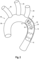
- FIG. 2 a schematic representation of the first embodiment of the intraluminal vascular prosthesis system according to the invention is shown, wherein the intraluminal main vascular prosthesis 12 is implanted in the aortic arch 50 or in the region of the descending aorta 52.
- the ascending branch also called aorta ascendens 56
- the aortic root sinus aorta
- the ascending aorta 56 is connected to the descending aorta 52 via the aortic arch 50.
- arterial head vessels branch off, namely the arterial trunk truncus brachiocephalicus 55, the common carotid artery 54 and the left subclavian artery 53.
- the main vascular prosthesis 12 of the intraluminal vascular prosthesis system 10 bridges an aneurysm in the area of the descending aorta 52.
- the blood flow coming from the ascending aorta 56 passes through the aortic arch 50 into the first lumen end 14 of the main vascular prosthesis 10 and leaves this at the second lumen end 15.
- the main vascular prosthesis 10 has a hollow cylindrical body on which a first lumen 13 is formed. This lumen 13 is formed by meandering stent rings 18, which together form the stent framework 16.
- the individual stent rings 18 are connected by a prosthetic material 17.
- the prosthetic material 17 is preferably made of a textile material or a film and is attached to the stent rings 18 by sewing, gluing or melting.
- the anchoring vascular prosthesis 20 can be surrounded by a prosthetic material 25. If it does not have a prosthetic material 25, the individual stent rings 26 are designed such that they form a coherent stent framework 24.
- the main vascular prosthesis 10 is preferably implanted in the vessel in such a way that a side vascular prosthesis 30 can be introduced into the lumen 21 of the anchoring vascular prosthesis 20 in the most space-saving way possible.
- This means that the side vascular prosthesis 30 is connected to the anchoring vascular prosthesis 20 in such a way that no accumulation of material occurs.
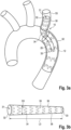
- Fig. 3a is a schematic representation of a first embodiment of the intraluminal vascular prosthesis system 10 according to the invention, wherein the intraluminal vascular prosthesis system 10 is implanted in the aortic arch 50 or the descending aorta 52.
- the intraluminal vascular prosthesis system 10 has a main vascular prosthesis 10 and a side vascular prosthesis 30.
- the main vascular prosthesis 10 corresponds to the one already described in Fig.2 described main vascular prosthesis 10.
- the side vascular prosthesis 30 with a length L3 has a continuous lumen 31 which extends from the first lumen end 32 to the second lumen end 33.
- the lumen 31 is formed in particular from the hollow cylindrical stent framework 34, which in turn is formed from individual stent rings 36.
- the individual stent rings 36 are connected to one another and are not surrounded by a prosthetic material.
- the side vessel 53 is supported by the side vessel prosthesis 30.
- the lateral vascular prosthesis 30 can also be only partially surrounded by a prosthetic material 35; preferably in the region of the second lumen end 33.
- Fig. 3a a schematic representation of a first embodiment of the hollow cylindrical lateral vascular prosthesis 30 is shown.
- the lateral vascular prosthesis 30 has a lumen 31 which extends from the first lumen end 32 to the second lumen end 33. This also defines the length L3 of the lateral vascular prosthesis 30.
- the lateral vascular prosthesis 30 has stent rings 36 which are connected to one another with a prosthetic material 35. The prosthetic material 35 and the individual stent rings 36 together form the hollow cylindrical stent framework 36.
- the lateral vessel prosthesis 30 tapers towards the second lumen end 33.
- the diameter D3 corresponds to the larger diameter at the first lumen end 32.
- the diameter at the first lumen end 32 corresponds to the diameter of the lateral vessel into which the lateral vessel prosthesis 30 is to be implanted
- the diameter at the second lumen end 33 corresponds to the diameter of the anchoring vessel prosthesis 20 into which the lateral vessel prosthesis 30 is to be introduced.
- FIG. 4 a schematic representation of a second embodiment of the intraluminal vascular prosthesis system 10 according to the invention is shown, wherein the intraluminal vascular prosthesis system 10 is implanted in the aortic arch 50 or the descending aorta 52.
- the vascular prosthesis system 10 in Fig. 4 differs from the vascular prosthesis system 10 in Fig. 3 shown in the fenestration or fenestration area 19 in the lateral surface.
- the second The lumen end 33 of the lateral vascular prosthesis 30 can be inserted at least partially into the lumen 13 of the main vascular prosthesis 12 and via the first lumen end 22 of the anchoring vascular prosthesis 20 into its lumen 13.
- a fenestration 19 can be designed as preformed holes or as an in-situ fenestration.
- the lateral vessels can continue to be supplied with blood by means of the lateral vascular prosthesis 30, which is inserted through the fenestration 19.
- This design offers the advantage that in addition to the aortic arch 50 and the descending aorta 52, the sublavia artery 53 is also supported by the vascular prosthesis system 10.
- the main vascular prosthesis consists of two hollow cylindrical stent framework sections 16a, 16b that can be connected to one another, such that a first stent framework section 16a has the anchoring prosthesis 20, and the second stent framework section 16b can be connected to the first stent framework section 16a to extend it.
- the side vascular prosthesis 30 can then be introduced via the second stent framework section 16b into the common lumen and into the anchoring prosthesis 20 present in the first stent framework section 16a.
- X-ray markers can be attached at certain positions (not shown) as a positioning aid during implantation and to check the position of the individual components of the vascular prosthesis system 10.
- X-ray markers are attached in the area of the lumen ends 14, 15, 22, 23, 32 and/or 33 or the fenestration 19.
Landscapes
- Health & Medical Sciences (AREA)
- Engineering & Computer Science (AREA)
- Biomedical Technology (AREA)
- Cardiology (AREA)
- Oral & Maxillofacial Surgery (AREA)
- Transplantation (AREA)
- Heart & Thoracic Surgery (AREA)
- Vascular Medicine (AREA)
- Life Sciences & Earth Sciences (AREA)
- Animal Behavior & Ethology (AREA)
- General Health & Medical Sciences (AREA)
- Public Health (AREA)
- Veterinary Medicine (AREA)
- Gastroenterology & Hepatology (AREA)
- Pulmonology (AREA)
- Prostheses (AREA)
Description
- Die vorliegende Erfindung betrifft eine intraluminale Gefäßprothese und ein intraluminales Gefäßprothesensystem zur Implantation im Bereich des Aortenbogens eines Patienten.
- Derartige Gefäßimplantate sind im Stand der Technik bspw. aus der
DE 103 37 739.5 bekannt. - Allgemein ist es bekannt, intraluminale Gefäßprothesen, die auch als endovaskuläre Gefäßstents/-stentgrafts bezeichnet werden, zur Behandlung von geschwächten, verletzten, gerissenen oder aneurysmatischen Gefäßen einzusetzen. Hierfür wird an der erkrankten oder verletzten Stelle des Gefäßes eine Gefäßprothese bzw. ein Stentgraft freigesetzt, die/der die Funktionalität des ursprünglichen Gefäßes wieder herstellt bzw. die noch bestehende Gefäßintegrität unterstützt.
- Dabei versteht man unter einem Aneurysma eine Ausweitung oder Aussackung eines arteriellen Blutgefäßes infolge angeborener oder erworbener Wandveränderungen. Die Aussackung kann dabei die Gefäßwand als Ganzes erfassen, oder, wie bei dem sogenannten falschen Aneurysma bzw. der sogenannten Dissektion, es tritt Blut aus dem Lumen des Gefäßes zwischen die Gefäßwandschichten und schert diese auseinander. Die Nichtbehandlung eines Aneurysma kann im fortgeschrittenen Stadium zu einer Ruptur der Arterie führen, mit der Folge, dass der Patient innerlich verblutet.
- Die zur Behandlung derartiger Aneurysmen verwendeten selbstexpandierenden Gefäßimplantate bestehen im Allgemeinen aus einem hohlzylindrischen Metallrahmen bzw.-gerüst, dessen Mantelfläche mit einer Textil- oder Polymerfolie abgedeckt ist, so dass sich ein hohlzylindrischer Körper ergibt. Zur Implantation wird die Gefäßprothese radial zusammengedrückt, so dass sich seine Querschnittsfläche deutlich verringert. Die Gefäßprothese wird dann mit Hilfe eines Einführsystems in den Bereich des Aneurysma gebracht, wo es freigesetzt wird. Auf Grund der Federwirkung des Metallrahmens/-gerüsts expandiert die Gefäßprothese wieder in seine ursprüngliche Form und spannt dabei seine Mantelfläche auf, die sich proximal und distal von dem Aneurysma innen in dem Blutgefäß verklemmt. Auf diese Weise fließt das Blut jetzt durch die Gefäßprothese und eine weitere Belastung der Aussackung wird verhindert.
- Der Metallrahmen solcher Gefäßprothesen besteht in der Regel bspw. aus einem Drahtgeflecht oder aus hintereinander angeordneten, mäanderförmig umlaufenden, sogenannten Stentfedern, die ggf. über Verbindungsstützen aus Draht miteinander verbunden sind, oder die lediglich über das Prothesenmaterial miteinander verbunden sind. Das Drahtgeflecht bzw. die Stentfedern sind üblicherweise aus einem Shape-Memory-Material, in der Regel aus Nitinol, wodurch die Stentfedern nach Einbringung in ein Gefäß zur Freisetzung wieder in den expandierten Zustand übergehen und das Gefäßimplantat dadurch "aufspannen".
- Allgemein treten Aneurysmen häufig im Bereich der Baucharterie (Aorta abdominalis) oder Brustarterie (Aorta thoracica) auf. Zur Behandlung von Aneurysmen in der Bauch- oder Brustarterie ist es bereits bekannt, die Arterie durch Implantation eines Stents soweit zu stabilisieren, dass eine Ruptur des Gefäßes vermieden wird.
- Aneurysmen können aber auch in dem sogenannten aufsteigenden Ast der Aorta (Aorta ascendens) auftreten. Der aufsteigende Ast der Aorta ist unmittelbar mit dem Herz verbunden. Ausgehend von der Aortenwurzel (Sinus aortae) verläuft der aufsteigende Ast in leicht gekrümmter Form vom Herz weg nach oben und geht dort in den Aortenbogen (Arcus aortae) über, und führt in den absteigenden Ast der Aorta (Aorta descendens). Im Bereich des Aortenbogens zweigen die Kopfgefäße ab, u.a. die linke und die rechte Halsschlagader. Der Aortenbogen weist einen Kurvenverlauf von etwa 180° mit einem sehr engen Radius auf und verbindet den aufsteigenden Ast der Aorta mit der Brustarterie und im weiteren Verlauf mit der Baucharterie.
- Nicht nur im Bereich des Aortenbogens ist es wichtig, vom Hauptgefäße abgehende Seiten-Gefäße durch die Positionierung der Gefäßprothese nicht zu blockieren, weshalb viele Gefäßprothesen offene Zonen oder sogenannte Fenestrierungen aufweisen, über welche vom Gefäßimplantat abgehende Seitenäste, die in die Seiten-Gefäße hineinragen, eingeführt und am Gefäßimplantat fixiert werden können.
- Gefäßerkrankungen wie Aneurysmen oder Dissektionen im Bereich des Aortenbogens werden bis heute in der Regel in einem invasiven offenen Eingriff behandelt. Eine solche Operation macht bisher regelmäßig zwei große, zeitlich getrennte Eingriffe erforderlich, und stellt einen sehr großen und aufwändigen und damit gefährlichen Eingriff dar, da nicht nur das Herz, sondern auch das Gehirn und die Bauchorgane des Patienten einer hypothermen Perfusion, d.h. also einer künstlichen, kalten extrakorporalen Durchblutung, bzw. einem hypothermen Durchblutungsstillstand unterzogen werden müssen. Mit einem solchen Eingriff sind jedoch nur wenige Herzchirurgen an erfahrenen Zentren vertraut.
- Aus der
WO 2013/025727 A1 ist eine Gefäßprothese bekannt, bei der über eine in der Prothesenwandung vorgesehene Öffnung, die wiederum in einer Vertiefung in der Wandung vorgesehen ist, Gefäßprothesen-Seitenäste im Lumen der Gefäßprothese verankert werden können. Aus derWO 2013/155306 A sind ferner verzweigte, doppellumige Gefäßprothesen bekannt. - Ferner sind gegenwärtig auch Stents und Stentgrafts bzw. Kombinationen von Stents bekannt, die minimalinvasiv eingeführt werden. Diese sind jedoch bei vielen Patienten mit erkrankten Gefäßen nur bedingt einsetzbar.
- Es besteht daher nach wie vor ein großes Bedürfnis nach Stent-/Stentgraftsystemen, bzw. Gefäßprothesen, die zur Implantation im Bereich des Aortenbogens und zur Behandlung von Gefäßerkrankungen im Bereich des Aortenbogens eingesetzt werden können.
- Aufgabe der vorliegenden Erfindung ist es daher, eine Gefäßprothese sowie ein Gefäßprothesensystem bereitzustellen, mit welchem der Bereich der aufsteigenden Aorta, des Aortenbogens und der absteigendem Aorta einer Vielzahl verschiedener Patienten mit unterschiedlichen Gefäßbeschaffenheiten schnell und unkompliziert behandelt werden können, bzw. das die oben geschilderten Eingriffe auch weniger erfahrenen Herzchirurgen ermöglicht.
- Gemäß der vorliegenden Erfindung wird diese Aufgabe gelöst durch ein intraluminales Gefäßprothesensystem zur Implantation im Bereich des Aortenbogens eines Patienten gemäß den beigefügten Ansprüchen, das zumindest folgendes aufweist: eine hohlzylindrische Haupt-Gefäßprothese, die ein durch die Haupt-Gefäßprothese geführtes Lumen, ein erstes Lumenende, ein zweites Lumenende, ein hohlzylindrisches Stentgerüst, ggf. mit einem daran befestigtes Prothesenmaterial, eine Länge L1 und einen Durchmesser D1 aufweist, wobei die hohlzylindrische Haupt-Gefäßprothese für die Implantation im Bereich des Aortenbogens und der Aorta descendens des Patienten ausgestaltet und dimensioniert ist, und wobei die Haupt-Gefäßprothese zumindest eine hohlzylindrische Verankerungs-Gefäßprothese aufweist, welche ein durch die Verankerungs-Gefäßprothese geführtes Lumen, ein erstes Lumenende, ein zweites Lumenende, ein hohlzylindrisches Stentgerüst, ggf. mit einem daran befestigtes Prothesenmaterial, eine Länge L2 und einen Durchmesser D2 aufweist, wobei die Verankerungs-Gefäßprothese innerhalb des Lumens der Haupt-Gefäßprothese zumindest über einen Teil der Länge L2 der Verankerungs-Gefäßprothese fest angebracht ist, und wobei der Durchmesser D2 der Verankerungs-Gefäßprothese um mindestens 45% kleiner ist als der Durchmesser D1 der Haupt-Gefäßprothese, und wobei die Länge L2 der Verankerungs-Gefäßprothese kleiner ist als die Länge L1 der Haupt-Gefäßprothese.
- Das erfindungsgemäße intraluminale Gefäßprothesensystem zur Implantation im Bereich des Aortenbogens umfasst ferner zumindest eine hohlzylindrische Seiten-Gefäßprothese, ein durch die Seiten-Gefäßprothese geführtes Lumen die ein erstes Lumenende, ein zweites Lumenende, ein hohlzylindrisches Stentgerüst, ggf. mit einem daran befestigtes Prothesenmaterial, eine Länge L3 und einen Durchmesser D3 aufweist, wobei die hohlzylindrische Seiten-Gefäßprothese für die Implantation zur Überbrückung des Abgangs der Arteria subclavia oder der Arteria carotis des Patienten ausgestaltet und dimensioniert ist, derart, dass die Seiten-Gefäßprothese mit ihrem ersten Lumenende in der Arteria subclavia oder der Arteria carotis positionierbar ist, und mit ihrem zweiten Lumenende zur sicheren Verankerung der Seiten-Gefäßprothese über das erste Lumenende der Verankerungs-Gefäßprothese zumindest teilweise in deren Lumen einführbar und darin fixierbar ist.
- Offenbart hierin ist ferner ein Verfahren zur Implantation eines intraluminalen Gefäßprothesensystems in den Aortenbogen eines Patienten, umfassend die folgenden Schritte:
- Einführen und Freisetzen der Haupt-Gefäßprothese in den Bereich des Aortenbogens und der Aorta descendens, und
- Einführen der Seiten-Gefäßprothese und Freisetzen derselben mit ihrem ersten Lumenende in der Arteria subclavia oder der Arteria carotis und mit ihrem zweiten Lumenende über das erste Lumenende der Verankerungs-Gefäßprothese zumindest teilwiese in deren Lumen.
- Die der Erfindung zugrunde liegende Aufgabe wird auf diese Weise vollkommen gelöst.
- Mit der neuen Gefäßprothese bzw. dem neuen Gefäßprothesen-System wird erreicht, dass auf einfache Weise ein geschwächtes, verletztes, gerissenes oder aneurysmatisches Gefäß, insbesondere im Bereich des Aortenbogens, behandelt werden kann. Erfindungsgemäß wird damit eine Gefäßprothese bereitgestellt, mit welcher die Möglichkeit geschaffen wird, Eingriffe insbesondere am Aortenbogen, bzw. in der aufsteigenden Aorta, dem Aortenbogen und der absteigenden Aorta, chirurgisch zu vereinfachen und zeitlich deutlich zu verkürzen.
- Insbesondere können durch die erfindungsgemäße Gefäßprothese bzw. das erfindungsgemäße Gefäßprothesensystem solche Gefäße behandelt werden, welche im Bereich der zu behandelnden Stelle abgehende Seitengefäße aufweisen. Durch den besonderen Aufbau können die Seitengefäße über zumindest eine Seiten-Gefäßprothese weiterhin mit Blut versorgt werden, wobei gleichzeitig die verletzten betroffenen Gefäße durch die intraluminale Gefäßprothese gestützt werden. Die Einführung und Platzierung dieses Systems kann durch dessen zumindest zweiteiligen Aufbau, aus hohlzylindrischer Hauptgefäßprothese zusammen mit der Verankerungs-Gefäßprothese und aus der Seiten-Gefäßprothese, präzise und einfach gehandhabt werden.
- Zur Einführung des Gefäßprothesensystems in ein Gefäß eines zu behandelnden Patienten wird zunächst die intraluminale Gefäßprothese an der gewünschten Stelle im Gefäß implantiert, bevorzugt hierbei ist der Aortenbogen. Anschließend wird eine Seiten-Gefäßprothese in das Seitengefäß implantiert, wobei das erste Lumenende im Seitengefäß positioniert wird während das zweite Lumenende zur sicheren Verankerung der Seiten-Gefäßprothese über das erste Lumenende der Verankerungs-Gefäßprothese zumindest teilweise in deren Lumen einführbar und darin fixierbar ist.
- Aufgrund des besonderen Aufbaus können die Gefäßprothese und die Seiten-Gefäßprothese getrennt voneinander implantiert werden. Die erfindungsgemäße Gefäßprothese sowie das erfindungsgemäße Gefäßprothesensystem bieten daher den Vorteil, dass nicht nur hoch spezialisierte Herzchirurgen die weiter oben geschilderten Eingriffe am Aortenbogen vornehmen können, sondern auch unerfahrene Fachkräfte. Ferner bietet die Erfindung den Vorteil, dass die Gefäßprothese sowie das Gefäßprothesensystem den jeweiligen anatomischen Verhältnissen des zu behandelnden Patienten angeglichen werden kann.
- Aufgrund des Aufbaus des erfindungsgemäßen Gefäßprothesensystems, bei dem die Seiten-Gefäßprothese in die Verankerungs-Gefäßprothese zumindest teilweise verankert bzw. "gesteckt" wird, können anatomisch sehr unterschiedliche Gefäße mit dem gleichen Gefäßprothesensystem behandelt werden. Dies kann erreicht werden durch die unterschiedliche Einsteck-/Verankerungstiefe der Seiten-Gefäßprothese in die Verankerungs-Gefäßprothese. Liegen die Seitengefäße weiter weg von der eigentlichen Haupt-Gefäßprothese, so kann die Einstecktiefe geringer ausgewählt werden, im Gegensatz zu einer größeren Verankerungstiefe bei nahgelegenen Seitengefäßen.
- Die Implantation des Gefäßprothesensystems ist insbesondere deshalb vereinfacht möglich, da die Haupt-Gefäßprothese nicht genau, in Bezug zu den abgehenden Seitengefäßen, ausgerichtet werden muss. Korrigiert werden kann die Ausrichtung durch das erfindungsgemäße "Verankerungssystem" und der damit verbundenen jeweiligen Einsteck-/Verankerungstiefe der Seiten-Gefäßprothese in die Verankerungs-Gefäßprothese. Gerade die Ausrichtung einer aus dem Stand der Technik bekannten einteiligen Gefäßprothese mit abgehenden Seitengefäßen erschwert nicht nur die Implantation, sondern auch die Fertigung solcher Implantate.
- Erfindungsgemäß kann sowohl die Haupt-Gefäßprothese, die zumindest eine Verankerungs-Gefäßprothese als auch die zumindest eine Seiten-Gefäßprothese als gecoverter oder ungecoverter Stent vorliegen; also gegebenenfalls mit einem Prothesenmaterial zumindest teilweise ummantelt sein, bzw. ein an dem Satengerüst befestigtes Prothesenmaterial aufweisen. Je nach Verletzung im Gefäß und den anatomischen Gegebenheiten kann es sinnvoll sein, dass zumindest eine der aufgeführten Gefäßprothesenteile kein Prothesenmaterial aufweist; beispielsweise die Seiten-Gefäßprothese oder die Verankerungs-Gefäßprothese.
- Insbesondere ist gemäß einer Ausführungsform bevorzugt, wenn die Haupt-Gefäßprothese, sofern sie ein Prothesenmaterial aufweist, einen Fenestrierungsbereich aufweist, also einen Bereich, über welchen die Seiten-Gefäßprothese in das Lumen der im Lumen der Haupt-Gefäßprothese vorliegenden Verankerungs-Gefäßprothese zumindest teilweise eingeführt und verankert werden kann. Dieser Fenestrierungsbereich kann bspw. ausgewählt sein aus Fenestrierungsbereichen im Prothesenmaterial, einzelnen Öffnungen im Mantelbereich der Haupt-Gefäßprothese, oder einen offenen Bereich, der sich umlaufend über den gesamten Umfang der Haupt-Gefäßprothese in diesem Bereich erstreckt.
- Alternativ kann die Seiten-Gefäßprothese über das erste Lumenende der Haupt-Gefäßprothese in das Lumen der im Lumen der Haupt-Gefäßprothese vorliegenden Verankerungs-Gefäßprothese zumindest teilweise eingeführt und verankert werden.
- Die Haupt-Gefäßprothese kann ferner gemäß einer Ausführungsform zumindest zwei Stentgerüst-Abschnitte aufweisen bzw. aus zumindest zwei Stentgerüst-Abschnitten bestehen, die verbindbar miteinander sind, bspw. durch teilweises Einführen des zweiten Stentgerüst-Abschnitt in den zweiten Stentgerüst-Abschnitt.
- Gemäß einer Ausführungsform der erfindungsgemäßen Gefäßprothese weist diese mehrere Verankerungs-Gefäßprothesen auf. Die Anzahl der Verankerungs-Gefäßprothesen richtet sich primär an der Anzahl der abgehenden Seitengefäße, welche durch die Seiten-Gefäßprothesen behandelt werden sollen.
- Gemäß einer Ausführungsform der vorliegenden Erfindung sind das erste Lumenende der Haupt-Gefäßprothese und das erste Lumenende der Verankerungs-Gefäßprothese bündig angeordnet.
- Dabei bedeutet "bündig angeordnet", dass die Verankerungs-Gefäßprothese mit ihrem ersten Lumenende am ersten Lumenende der Haupt-Gefäßprothese ausgerichtet ist und damit beide Lumenenden sozusagen auf gleicher Ebene enden. Die Verankerungs-Gefäßprothese erstreckt sich bei dieser Ausfürhungsform damit vom ersten Lumenende der Haupt-Gefäßprothese im Lumen der Haupt-Gefäßprothese in Richtung des zweiten Lumenendes entlang der Innenwand der Haupt-Gefäßprothese. Der Zugang zur Verankerungs-Gefäßprothese für eine Seitengefäßprothese findet damit nicht über eine Seitenwand oder eine Fenestrierung in der Haupt-Gefäßprothese statt, sondern über das erste Lumenende der Hauptgefäßprothese.
- Nachstehend werden einige hierin verwendeten Begriffe, die zwar für den Fachmann an sich und unter Heranziehung der vorliegenden Offenbarung klar sind, näher definiert:
- Grundsätzlich werden bei Stentgrafts oder endoluminalen Prothesen allgemein sowie vorliegend zur Bezeichnung der jeweiligen Enden die Begriffe "distal" und "proximal" verwendet, wobei der Begriff "distal" der Teil bzw. das Ende bezeichnet wird, der/das in Bezug auf den Blutstrom weiter stromabwärts liegt. Der Begriff "proximal" hingegen bezeichnet, wieder in Bezug auf den Blutstrom, einen Teil bzw. das Ende, der/das in Bezug auf den Blutstrom weiter stromaufwärts liegt. Anders ausgedrückt bedeuten der Begriff "distal" in Richtung des Blutstroms, und der Begriff "proximal" der Richtung des Blutstroms entgegengesetzt. Bei Kathetern hingegen, bzw. Einführsystemen bezeichnet der Begriff "distal" das Ende des Katheters bzw. des Einführsystems, das in den Patienten eingeführt wird, bzw. das vom Anwender ausgesehen am Entferntesten liegt, und der Begriff "proximal" das Ende, das sich dem Anwender näher zugewandt ist.
- Entsprechend sind vorliegend die "proximale" und die "distale" Öffnung des Gefäßimplantats die Öffnungen, durch die hindurch der Blutfluss durch das hohlzylindrische Lumen der Gefäßimplantat gewährleistet wird: Wenn das erfindungsgemäße Gefäßimplantat in einem Blutgefäß wie beispielsweise der Aorta implantiert ist, fließt also das vom Herzen kommende Blut durch die proximale Öffnung des Gefäßimplantats, und verlässt das Gefäßimplantat durch deren distale Öffnungen. Die hohlzylindrische Haupt-Gefäßprothese bzw. dessen Verankerungs-Gefäßprothese, als auch die Seiten-Gefäßprothese können dabei über ihre Gesamtlänge hinweg einen einheitlichen Durchmesser, oder aber unterschiedliche Durchmesser aufweisen.
- Bei dem hohlzylindrische Stentgerüst handelt es sich erfindungsgemäß um einen Metallrahmen, der in der Regel bspw. aus einem Drahtgeflecht oder aus hintereinander angeordneten, mäanderförmig umlaufenden, sogenannten Stentfedern, die ggf. über Verbindungsstützen aus Draht miteinader verbunden sind, oder die lediglich über das Prothesenmaterial miteinander verbunden sind. Das Drahtgeflecht bzw. die Stentfedern sind üblicherweise aus deinem Shape-Memory-Material, in der Regel aus Nitinol, wodurch die Stentfedern nach der Implantation in ein Gefäß zur Freisetzung wieder in den expandierten Zustand übergehen und die Gefäßprothese dadurch "aufspannt".
- Gemäß einer ersten Ausführungsform des erfindungsgemäßen Gefäßprothesensystems weist/weisen die Haupt-Gefäßprothese und/oder die Verankerungs-Gefäßprothese und/oder die Seiten-Gefäßprothese ein Stentgerüst sowie ein daran befestigtes Prothesenmaterial auf.
- Dabei bedeutet vorliegend "Stentgerüst" jedes Metallgerüst, das durch ein Aufspannen oder durch eine Expansion des Gerüsts einer Gefäßprothese eine Expansionskraft zur Offenhaltung eines Gefäßes verleiht, ggf. in Kombination mit einem an dem Gerüst befestigten Prothesenmaterial. Das Prothesenmaterial besteht bevorzugt aus einem bioverträglichen Material, was dazu führt, dass der Kontakt zwischen dem Gefäßimplantat und der Gefäßwand komplikationsfrei ist.
- In diesem Zusammenhang ist bevorzugt, wenn das Prothesenmaterial ein Material aufweist, das ausgewählt ist aus einem Textil oder einem Polymer. Insbesondere ist bevorzugt, wenn das Prothesenmaterial ein Material aufweist oder aus diesem gebildet ist, das ausgewählt ist aus Polyester, Polyurethan, Polystyrol, Polytetrafluorethylen ultrahochmolekulargewichtiges Polyethylen (UHMPE), oder Mischungen davon.
- Gemäß einer weiteren Ausführungsform des erfindungsgemäßen Gefäßprothesensystems ist das Stentgerüst der Haupt-Gefäßprothese und/oder das Stentgerüst der Verankerungs-Gefäßprothese und/oder das Stentgerüst der Seiten-Gefäßprothese ausgewählt aus einem laser-geschnittenen Stentgerüst, einzelnen Stentfedern oder einem geflochtenen Stentgerüst.
- Dabei wird unter "Stentgerüst" jede Ausbildung eines Stents verstanden, bei der verschieden Draht-Stränge derart miteinander verflochten, ineinander verschlungen oder anderweitig verknüpft sind, dass sich eine Struktur mit Zonen, Bereichen oder Punkten bildet, an denen die Stränge übereinander liegen, und mit Zonen oder Bereichen, die frei von den Drahtsträngen sind und daher Öffnungen oder Fenster oder Maschen bilden. Entsprechend weist auch ein Laser-geschnittenes Stent-Stützgerüst Maschen oder Öffnungen auf. Vorzugsweise sind die Öffnungen, Maschen oder Fenster hierbei diamantförmig.
- Vorliegend wird unter einer "Stentfeder" jedes einstückige, ringförmige Element verstanden, das sich aufgrund dessen Materials komprimieren lässt, und sich nach Entfernung des Kompressionsdrucks wieder federartig expandieren kann.
- Gemäß einer Ausführungsform weist das Stentgerüst der Haupt-Gefäßprothese und/oder das Stentgerüst der Verankerungs-Gefäßprothese und/oder das Stentgerüst der Seiten-Gefäßprothese hintereinander angeordnete, nicht miteinander verbundene mäanderförmige umlaufende Stentringe sowie ein mit den Stentringen fest verbundenes Prothesenmaterial auf.
- Dabei wird vorliegend unter einem "Stentring" jedes einstückige, ringförmige Element verstanden, das durch einen umlaufenden Draht gebildet, und einen im Wesentlichen runden Umfang besitzt. Der Draht des Stentrings kann dabei in Wellen verlaufen, wobei sich Wellenberg und Wellental, die eine Phase oder Amplitude bilden, abwechseln. Dabei wird unter "mäanderförmig" vorliegend jeder schlingen- bzw. schleifenförmige Verlauf" des Stentrings bzw. des Stentdrahtes verstanden.
- Das gegebenenfalls oder zwingend (bei den Stentringen) einzusetzende bzw. vorliegende Prothesenmaterial der im erfindungsgemäßen System einzusetzenden Gefäßprothesen weist dabei vorzugswiese ein Material auf, das ausgewählt ist aus einem Textil oder einem Polymer.
- Dabei können das Prothesenmaterial der Haupt-Gefäßprothese und/oder der Verankerungs-Gefäßprothese und/oder der Seiten-Gefäßprothese, sofern diese jeweils oder auch nur eines oder zwei davon ein Prothesenmaterial aufweisen, aus einem solchen Material gebildet sein, oder ein solches aufweisen.
- Gemäß einer weiteren Ausführungsform weist der mäaderförmgie Umlauf von zumindest einem Stentring des Stentgerüsts eine ungleichmäßige Amplitude auf.
- Gemäß dieser Ausführungsform wird ein Gefäßprothesensystem bereitgestellt, welches insbesondere in gekrümmten Gefäßen, bspw. dem Aortenbogen, eingesetzt werden können, da es durch die ungleichmäßigen Amplituden nicht zu unnötiger Materialanhäufung in der Gefäßprothese im Bereich der Krümmung kommt.
- Gemäß einer Ausführungsform ist das Stentgerüst der Haupt-Gefäßprothese und/oder das Stentgerüst der Verankerungs-Gefäßprothese und/oder das Stentgerüst der Seiten-Gefäßprothese selbstexpandierbar.
- Dies bedeutet, dass das Stentgerüst von einem komprimierten Zustand in einen expandierten Zustand überführbar ist, wobei der komprimierte Zustand durch ein das Stentgerüst - sowie ggf. das daran befestigte Prothesenmaterial - komprimierendes und rückziehbares Element, bspw. eine Hülle, erreicht wird, die sich zur Einführung in ein Gefäß über dem Stentgerüst zu dessen Komprimierung befindet. Nach korrekter Platzierung wird das das Stentgerüst komprimierende Element entfernt, woraufhin das Stentgerüst expandiert und sich dessen Wände sich an die Gefäßwand drücken, wodurch die Gefäßprothese im Gefäß fixiert wird.
- Allgemein ist bevorzugt, wenn das Stentgerüst aus einem selbstexpandierenden Material besteht oder ein solches aufweist. Hierbei ist insbesondere bevorzugt, wenn das Material Nitinol ist.
- Gemäß einer Ausführungsform ist der Durchmesser D1 der Haupt-Gefäßprothese von 24 mm bis 42 mm, insbesondere 24 mm, 26 mm, 28 mm, 30 mm, 32 mm, 34 mm, 36 mm, 38 mm, 40 mm oder 42 mm.
- Gemäß einer weiteren Ausführungsform ist der Durchmesser D2 der Verankerung-Gefäßprothese von 6 mm bis 14 mm, insbesondere 6 mm, 7 mm, 8 mm, 9 mm, 10 mm, 11 mm, 12 mm, 13 mm oder 14 mm.
- Gemäß einer weiteren Ausführungsform ist der Durchmesser D3 der Seiten-Gefäßprothese von 6 mm bis 16 mm, insbesondere 6 mm, 7 mm, 8 mm, 9 mm, 10 mm, 11 mm, 12 mm, 13 mm, 14 mm, 15 mm oder 16 mm.
- Gemäß diesen Ausführungsformen kann der Durchmesser D1, D2 und D3 an das jeweilige zu behandelnde Gefäß angepasst werden. Die genannten Maße entsprechen dabei insbesondere den Durchmessern innerhalb des Aortenbogens bzw. der Arteria Truncus brachiocephalicus, der Arteria carotos communis und der Arterie subclavia sinistra. Die Haupt-Gefäßprothese, die Verankerung-Gefäßprothese sowie die Seiten-Gefäßprothese kann erfindungsgemäß über die gesamte Länge hinweg einen einheitlichen Durchmesser, oder aber unterschiedliche Durchmesser aufweisen. Sofern die jeweiligen Gefäßprothesenteile einen unterschiedlichen Durchmesser aufweisen, so entsprechen die genannten Durchmesser von D1, D2 und D3 dieser Ausführungsformen den größten bzw. maximalen Durchmessern.
- Gemäß einer weiteren Ausführungsform ist die Verankerungs-Gefäßprothese im Lumen der Haupt-Gefäßprothese an einer Innenwand angebracht, vorzugsweise angenäht, angeklebt, oder angeschweißt.
- Eine sichere Befestigung der Verankerungs-Gefäßprothese im Lumen der Haupt-Gefäßprothese ist bevorzugt, da sich diese ansonsten ungewollt von der Haup-Gefäßprothese lösen kann. Dies kann durch die Ausführungsform gewährleistet werden. Die Verankerungs-Gefäßprothese ist aufgrund ihres Aufbaus nicht selbst im Gefäß verankert, wie bspw. die Haupt-Gefäßprothese bzw. die Seiten-Gefäßprothese. Aufgrund eines starken Blutflusses innerhalb der Gefäßprothese kann sich demnach die Verankerungs-Gefäßprothese gegebenenfalls lösen und sich ungewollt verschieben. Dieser Nachteil wird durch die beschriebene Ausführungsform vermieden.
- Erfindungsgemäß ist das zweite Lumenende der Seiten-Gefäßprothese über das erste Lumenende der Haupt-Gefäßprothese in das erste Lumenende der Verankerungs-Gefäßprothese und zumindest teilweise in deren Lumen einführbar.
- Damit ist es vereinfacht möglich Seitengefäße mit einer Seiten-Gefäßprothese zu versehen. Mittels des Verankerungssystems der Seiten-Gefäßprothese in die Verankerungs-Gefäßprothese ist es auch einem unerfahrenen Herzchirurgen möglich derartige Implantationen durchführen zu können, da die Haupt-Gefäßprothese nicht notwendigerweise genau auf die Seitengefäße ausgerichtet sein muss. Ein Fehler innerhalb der Implantation betreffend die Lokation der Haupt-Gefäßprothese kann durch das Ineinanderstecken ausgeglichen werden.
- Gemäß einer weiteren Ausführungsform weist die Haupt-Gefäßprothese eine Mantelfläche sowie eine in der Mantelfläche vorgesehene Fenestrierung auf, über welche das zweite Lumenende der Seiten-Gefäßprothese ins Lumen der Haupt-Gefäßprothese und über das erste Lumenende der Verankerungs-Gefäßprothese in deren Lumen zumindest teilweise einführbar ist.
- Unter fenestrierten Gefäßprothesen werden solche verstanden, die präformierte Löcher (Fenestrationen) aufweisen, um ein oder mehrere Gefäßabgänge in der Gefäßprothese zu ermöglichen. Gemäß dieser Ausführungsform ist es möglich, seitlich abgehende Blutgefäße über eine Seiten-Gefäßprothese weiter mit Blut zu versorgen und gleichzeitig das Hauptgefäß durch eine Haupt-Gefäßprothese zu stützen.
- Alternativ kann die Fenestrierung als in-situ Fenestrierung ausgestaltet sein. Hierbei wird die Fenestrierung erst eingebracht, nachdem die Gefäßprothese im Gefäß positioniert wurde. Hier wird die Haupt-Hauptgefäßprothese in situ mit einer Nadel penetriert, um ein Nadelloch in der Mantelfläche des Prothesenmaterials zu bilden. Anschließend wird eine Dilator-Anordnung durch das Nadelloch geschoben, um das Nadelloch zu erweitern.
- Die Mantelfläche ist bevorzugt aus einem Prothesenmaterial ausgestaltet, welches mit dem Stentgerüst der Haupt-Gefäßprothese verbunden ist.
- Das erfindungsgemäße intraluminale Gefäßprothesensystem kann zur Behandlung von Gefäßerkrankungen eines Patienten, insbesondere im Bereich des Aortenbogens und der Aorta descendens verwendet werden.
- In dem hierin offenbarten Verfahren kann die Seiten-Gefäßprothese über das erste Lumenende der Haupt-Gefäßprothese in das Lumen der Verankerungs-Gefäßprothese eingeführt werden.
- In dem hierin offenbarten Verfahren kann die Haupt-Gefäßprothese ein Mantelfläche sowie eine in der Mantelfläche vorgesehene Fenestrierung aufweisen, und die Seiten-Gefäßprothese kann über die Fenestrierung in der Haupt-Gefäßprothese ins Lumen der Haupt-Gefäßprothese und über das erste Lumenende der Verankerungs-Gefäßprothese in deren Lumen zumindest teilweise eingeführt werden.
- Die für die erfindungsgemäße Gefäßprothese bzw. das erfindungsgemäße Gefäßprothesensystem beschriebenen Merkmale, Eigenschaften und Vorteile können für die hierin offenbarten Verfahren entsprechend angewandt werden.
- Weitere Vorteile ergeben sich aus den Figuren und der nachstehenden Beschreibung bevorzugter Ausführungsbeispiele.
- Es versteht sich, dass die vorstehend genannten und die nachstehend noch zu erläuternden Merkmale nicht nur in der jeweils angegebenen Kombination, sondern auch in anderen Kombinationen oder in Alleinstellung verwendbar sind, ohne den Rahmen der vorliegenden Erfindung zu verlassen.
- Ausführungsbeispiele der Erfindung sind in der Zeichnung dargestellt und werden in der nachfolgenden Beschreibung näher erläutert. Es zeigen:
-
Fig. 1 eine schematische Darstellung einer ersten Ausführungsform einer Haupt-Gefäßprothese einer erfindungsgemäßen intraluminalen Gefäßprothese; -
Fig. 2 eine schematische Darstellung der Ausführungsform ausFig. 1 , wobei die intraluminale Haupt-Gefäßprothese im Aortenbogen bzw. der Aorta descendens implantiert vorliegt; -
Fig. 3a eine schematische Darstellung einer ersten Ausführungsform des erfindungsgemäßen intraluminalen Gefäßprothesensystem, wobei das intraluminale Gefäßprothesensystem im Aortenbogen bzw. der Aorta descendens implantiert vorliegt; -
Fig. 3b eine schematische Darstellung einer ersten Ausführungsform der hohlzylindrischen Seiten-Gefäßprothese; und -
Fig. 4 eine schematische Darstellung einer zweiten Ausführungsform des erfindungsgemäßen intraluminalen Gefäßprothesensystem, wobei das intraluminale Gefäßprothesensystem im Aortenbogen bzw. der Aorta descendens implantiert vorliegt. - In den Figuren werden gleiche Merkmale mit gleichen Bezugszeichen versehen, wobei aus Gründen der Übersichtlichkeit nicht in allen Figuren immer sämtliche Bezugszeichen angegeben sind.
-
Fig. 1 zeigt eine schematische Darstellung von Teilen einer ersten Ausführungsform eines erfindungsgemäßen intraluminalen Gefäßprothesensystems. Das hier gezeigte Gefäßprothesensystem 10 weist zwei separate Gefäßprothesen auf, die miteinander fest verbunden sind; zum einen die Haupt-Gefäßprothese 12 und zum anderen die Verankerungs-Gefäßprothese 20. Die Befestigung der Verankerungs-Gefäßprothese 20 an der Haupt-Gefäßprothese 12 kann beispielsweise durch Annähen, Ankleben oder Anschweißen erreicht werden. Sowohl die Haupt-Gefäßprothese 12, als auch die Verankerungs-Gefäßprothese 20 weisen jeweils ein Lumen 13 und 21 auf. Dieses erstreckt sich jeweils vom ersten Lumenende 14 und 22 bis zum zweiten Lumenende 15 und 23, sodass eine Länge L1 und L2 gebildet wird. Die hohlzylindrische Struktur der Hauptgefäßprothese 12 bzw. der Verankerungs-Gefäßprothese 20, mit dem Durchmesser D1 und D2, wird insbesondere erreicht durch das jeweilige hohlzylindrische Stentgerüst 16 und 24 und das jeweilig umgebende Prothesenmaterial 17 und 25. In dieser Darstellung ist das Stentgerüst 16 und 24 jeweils aus einzelnen Stentringen 18 und 26 aufgebaut, die nur über das Prothesenmaterial 17 und 18 miteinander verbunden sind. - Die Dimension der hohlzylindrischen Haupt-Gefäßprothese 12 entspricht in etwa der Dimension des Aortenbogens und der Aorta decendens. Dies ermöglicht eine einfache Implantation in das Gefäß. Je nach Beschaffenheit des Gefäßes der einzelnen Patienten können die Dimensionen des intraluminalen Gefäßprothesensystems angepasst werden. Insbesondere ist der Durchmesser D1 der Haupt-Gefäßprothese 12 an den Durchmesser der Aorta descendens angepasst, derart, dass diese im expandierten Zustand an die Gefäßwand gedrückt wird. Unter Umständen ist es bevorzugt, wenn die Haupt-Gefäßprothese 12 und/oder die Verankerungs-Gefäßprothese 20 über die Länge L1 bzw. L2 einen unterschiedlichen Durchmesser D1 bzw. D2 aufweisen.
- Die Verankerungs-Gefäßprothese 20 ist zumindest über einen Teil der Länge L2 innerhalb des Lumens 13 der Haupt-Gefäßprothese fest angebracht, wobei der Durchmesser D2 der Verankerungs-Gefäßprothese 20 um mindestens 45% kleiner ist als der Durchmesser D1 der Haupt-Gefäßprothese 12. Zudem ist die Länge L2 der Verankerungs-Gefäßprothese 20 kleiner als die Länge L1 der Haupt-Gefäßprothese 12.
- Dieser Aufbau des erfindungsgemäßen Gefäßprothesensystems ermöglicht es, im Bereich der aufsteigenden Aorta, des Aortenbogens und der absteigendem Aorta eine Vielzahl an Patienten mit unterschiedlichen Gefäßbeschaffenheiten behandeln zu können.
- Die innenliegende hohlzylindrische Verankerungs-Gefäßprothese 20 dient insbesondere dem Zweck, dass zumindest teilweise innerhalb des Lumens 21 eine weitere hohlzylindrische Seiten-Gefäßprothese 30 mit ihrem zweiten Lumenende in diesem einführbar und darin fixierbar ist (in dieser Figur nicht gezeigt).
- In
Fig. 2 ist eine schematische Darstellung der ersten Ausführungsform des erfindungsgemäßen intraluminalen Gefäßprothesensystems gezeigt, wobei die intraluminale Haupt-Gefäßprothese 12 im Aortenbogen 50 bzw. im Bereich der Aorta descendens 52 implantiert vorliegt. - Der aufsteigende Ast, auch Aorta ascendens 56 genannt ist über die in
Fig. 2 nicht gezeigte Aortenwurzel (Sinus aorta) mit der ebenfalls nicht dargestellten linken Kammer des Herzens verbunden. Die Aorta ascendens 56 ist über den Aortenbogen 50 mit der Aorta descendens 52 verbunden. Im Bereich des Aortenbogens 50 gehen arterielle Kopfgefäße ab, nämlich der Arterienstamm Truncus brachiocephalicus 55, die Arteria carotos communis 54 und die Arteria subclavia sinistra 53. - Die Haupt-Gefäßprothese 12 des intraluminalen Gefäßprothesensystems 10 überbrückt in der gezeigten Darstellung ein Aneurysma im Bereich der Aorta descendens 52. Der aus der Aorta ascendens 56 kommende Blutstrom gelangt über den Aortenbogen 50 in das erste Lumenende 14 der Haupt-Gefäßprothese 10 und verlässt diesen am zweiten Lumenende 15. Zu diesem Zweck weist die Haupt-Gefäßprothese 10 einen hohlzylindrischen Körper auf welcher ein erstes Lumen 13 formt. Dieses Lumen 13 ist gebildet durch mäanderförmige Stentringe 18, die insgesamt das Stentgerüst 16 bilden. Verbunden sind die einzelnen Stentringe 18 durch ein Prothesenmaterial 17. Das Prothesenmaterial 17 ist bevorzugt aus einem textilen Material oder eine Folie und ist durch Nähen, Kleben oder Einschmelzen an den Stentringen 18 befestigt.
- Die Verankerungs-Gefäßprothese 20 kann mit einem Prothesenmaterial 25 umgeben sein. Sofern diese kein Prothesenmaterial 25 aufweist, so sind die einzelnen Stentringe 26 derart ausgebildet, dass diese ein zusammenhängendes Stentgerüst 24 bilden.
- Die Haupt-Gefäßprothese 10 ist bevorzugt derart im Gefäß implantiert, dass eine Seiten-Gefäßprothese 30 möglichst platzsparend in das Lumen 21 der Verankerungs-Gefäßprothese 20 eingeführt werden kann. Das bedeutet, dass die Seiten-Gefäßprothese 30 derart mit der Verankerung-Gefäßprothese 20 verbunden wird, dass es nicht zu einer Materialanhäufung kommt.
- In
Fig. 3a ist eine schematische Darstellung einer ersten Ausführungsform des erfindungsgemäßen intraluminalen Gefäßprothesensystems 10 gezeigt, wobei das intraluminale Gefäßprothesensystem 10 im Aortenbogen 50 bzw. der Aorta descendens 52 implantiert vorliegt. Das intraluminalen Gefäßprothesensystem 10 weist eine Haupt-Gefäßprothese 10 sowie eine Seiten-Gefäßprothese 30 auf. Die Haupt-Gefäßprothese 10 entspricht dabei der bereits inFig.2 beschriebenen Haupt-Gefäßprothese 10. - Die Seiten-Gefäßprothese 30 mit einer Länge L3 weist ein durchgängiges Lumen 31 auf, welches sich vom ersten Lumenende 32 bis zum zweiten Lumenende 33 erstreckt. Das Lumen 31 wird insbesondere aus dem hohlzylindrischen Stentgerüst 34 gebildet, welches wiederrum aus einzelnen Stentringen 36 ausgebildet ist. In dieser Darstellung sind die einzelnen Stentringe 36 untereinander verbunden und nicht mit einem Prothesenmaterial umgeben. In dieser Ausgestaltung kann das Blut, kommend vom Aortenbogen, durch das Stentgerüst 34 hindurch in das abgehende Seitengefäß 53 fließen. Gleichzeitig ist das Seitengefäß 53 gestützt durch die Seiten-Gefäßprothese 30.
- In einer nicht dargestellten Ausführungsform kann die Seiten-Gefäßprothese 30 auch nur teilweise durch ein Prothesenmaterial 35 umgeben sein; bevorzugt im Bereich des zweiten Lumenendes 33.
- In
Fig. 3a ist eine schematische Darstellung einer ersten Ausführungsform der hohlzylindrischen Seiten-Gefäßprothese 30 gezeigt. Die Seiten-Gefäßprothese 30 weist ein Lumen 31 auf, welches sich vom ersten Lumenende 32 bis hin zum zweiten Lumenende 33 erstreckt. Hierdurch definiert sich auch die Länge L3 der Seiten-Gefäßprothese 30. In dieser Darstellung weist die Seiten-Gefäßprothese 30 Stentringe 36 auf, welche untereinander mit einem Prothesenmaterial 35 verbunden sind. Das Prothesenmaterial 35 sowie die einzelnen Stentringe 36 bilden zusammen das hohlzylindrische Stentgerüst 36. - In dieser Ausgestaltung verjüngt sich die Seiten-Gefäßprothese 30 zum zweiten Lumenende 33 hin. Der Durchmesser D3 entspricht in dieser Darstellung dem größeren Durchmesser am ersten Lumenende 32. In dieser Ausgestaltung entspricht der Durchmesser am ersten Lumenende 32 dem Durchmesser des Seitengefäßes, in welches die Seiten-Gefäßprothese 30 implantiert werden soll, und der Durchmesser am zweiten Lumenende 33 dem Durchmesser der Verankerungs-Gefäßprothese 20, in welche die Seiten-Gefäßprothese 30 eingeführt werden soll.
- In
Fig. 4 ist eine schematische Darstellung einer zweiten Ausführungsform des erfindungsgemäßen intraluminalen Gefäßprothesensystem 10 gezeigt, wobei das intraluminale Gefäßprothesensystem 10 im Aortenbogen 50 bzw. der Aorta descendens 52 implantiert vorliegt. - Das Gefäßprothesensystem 10 in
Fig. 4 unterscheidet sich von dem Gefäßprothesensystem 10 inFig. 3 gezeigt in der, in der Mantelfläche aufweisenden, Fenestrierung bzw. Fenestrierungsbereich 19. Über diese Fenestrierung 19 ist das zweite Lumenende 33 der Seiten-Gefäßprothese 30 ins Lumen 13 der Haupt-Gefäßprothese 12 und über das erste Lumenende 22 der Verankerung-Gefäßprothese 20 in deren Lumen 13 zumindest teilweise einführbar. Eine Fenestrierung 19 kann als präformierte Löcher ausgestaltet sein oder als in-situ Fenestrierung. Mittels der Seitengefäßprothese 30, welche durch die Fenestrierung 19 hindurch gesteckt ist, können die Seitengefäße weiterhin mit Blut versorgt werden. Diese Ausgestaltung bietet den Vorteil, dass neben dem Aortenbogen 50 und der Aorta descendens 52 auch die Arteria sublavia 53 mittels des Gefäßprothesensystems 10 unterstützt wird. - Gemäß einer weiteren Ausführungsform kann also, wie in
Fig. 4 gezeigt, auch vorgesehen sein, dass die Haupt-Gefäßprothese aus zwei, miteinander verbindbaren hohlzylindrischen Stentgerüst-Abschnitten 16a, 16b, besteht, derart, dass ein erster Stentgerüst-Abschnitt 16a die Verankerungs-Prothese 20 aufweist, und der zweite Stentgerüst-Abschnitt 16b zur Verlängerung des ersten Stentgerüst-Abschnitts 16a mit diesem verbunden werden kann. Die Seiten-Gefäßprothese 30 kann dann über den zweiten Stentgerüst-Abschnitt 16b in das gemeinsame Lumen und in die im ersten Stentgerüst-Abschnitt 16a vorliegende Verankerungs-Prothese 20 eingeführt werden.. - Als Positionierungshilfe während der Implantation und zur Überprüfung der Lage der einzelnen Bestandteile des Gefäßprothesensystems 10, können Röntgenmarker an bestimmten Positionen angebracht werden (nicht gezeigt). Beispielsweise werden derartige Röntgenmarker im Bereich der Lumenenden 14, 15, 22, 23, 32 und/oder 33 oder der Fenestrierung 19 angebracht.
Claims (11)
- Intraluminales Gefäßprothesensystem (10) zur Implantation im Bereich des Aortenbogens (50) eines Patienten, umfassend:- eine hohlzylindrische Haupt-Gefäßprothese (12), die ein durch die Haupt-Gefäßprothese geführtes Lumen (13), ein erstes Lumenende (14), ein zweites Lumenende (15), ein hohlzylindrisches Stentgerüst (16), ggf. mit einem daran befestigtes Prothesenmaterial (17), eine Länge L1 und einen Durchmesser D1 aufweist, wobei die hohlzylindrische Haupt-Gefäßprothese (12) für die Implantation im Bereich des Aortenbogen (50) und der Aorta descendens (52) des Patienten ausgestaltet und dimensioniert ist, und wobei die Haupt-Gefäßprothese (12)- zumindest eine hohlzylindrische Verankerungs-Gefäßprothese (20) aufweist, welche ein durch die Verankerungs-Gefäßprothese geführtes Lumen (21), ein erstes Lumenende (22) , ein zweites Lumenende (23), ein hohlzylindrisches Stentgerüst (24), ggf. mit einem daran befestigtes Prothesenmaterial (25), eine Länge L2 und einen Durchmesser D2 aufweist, wobei die Verankerungs-Gefäßprothese (20) innerhalb des Lumens (13) der Haupt-Gefäßprothese (12) zumindest über einen Teil der Länge L2 der Verankerungs-Gefäßprothese (20) fest angebracht ist, und wobei der Durchmesser D2 der Verankerungs-Gefäßprothese (20) um mindestens 45% kleiner ist als der Durchmesser D1 der Haupt-Gefäßprothese (12), und wobei die Länge L2 der Verankerungs-Gefäßprothese (20) kleiner ist als die Länge L1 der Haupt-Gefäßprothese (12), wobei das Gefäßprothesensystem (10) ferner- zumindest eine hohlzylindrische Seiten-Gefäßprothese (30) umfasst, mit einem durch die Seiten-Gefäßprothese (30) geführten Lumen (31), wobei die Seiten-Gefäßprothese (30) ein erstes Lumenende (32), ein zweites Lumenende (33), ein hohlzylindrisches Stentgerüst (34), ggf. mit einem daran befestigtes Prothesenmaterial (35), eine Länge L3 und einen Durchmesser D3 aufweist, und wobei die hohlzylindrische Seiten-Gefäßprothese (30) für die Implantation zur Überbrückung des Abgangs der Arteria subclavia (53) und/oder der Arteria carotis (54) des Patienten ausgestaltet und dimensioniert ist, derart, dass die Seiten-Gefäßprothese (30) mit ihrem ersten Lumenende (32) in der Arteria subclavia (53) und/oder der Arteria carotis (54) positionierbar ist, und mit ihrem zweiten Lumenende (33) zur sicheren Verankerung der Seiten-Gefäßprothese (30) über das erste Lumenende (23) der Verankerungs-Gefäßprothese (20) zumindest teilweise in deren Lumen (21) einführbar und darin fixierbar ist, und wobei das zweite Lumenende (33) der Seiten-Gefäßprothese (30) über das erste Lumenende (14) der Haupt-Gefäßprothese (12) in das erste Lumenende (22) der Verankerungs-Gefäßprothese (20) und zumindest teilweise in deren Lumen (21) einführbar ist.
- Intraluminales Gefäßprothesensystem (10) nach Anspruch 1, dadurch gekennzeichnet, dass die Haupt-Gefäßprothese (12) und/oder die Verankerungs-Gefäßprothese (20) und/oder die Seiten-Gefäßprothese (30) ein Stentgerüst (16; 24; 34) sowie ein daran befestigtes Prothesenmaterial (17; 25; 35) aufweist bzw. aufweisen.
- Intraluminales Gefäßprothesensystem (10) nach Anspruch 1 oder 2, dadurch gekennzeichnet, dass das Stentgerüst (16) der Haupt-Gefäßprothese (12) und/oder das Stentgerüst (24) der Verankerungs-Gefäßprothese (20) und/oder das Stentgerüst (34) der Seiten-Gefäßprothese (30) ausgewählt ist aus einem laser-geschnittenen Stentgerüst, einzelnen Stentfedern oder einem geflochtenen Stentgerüst.
- Intraluminales Gefäßprothesensystem (10) nach einem der Ansprüche 1 bis 3, dadurch gekennzeichnet, dass das Stentgerüst (16) der Haupt-Gefäßprothese (12) und/oder das Stentgerüst (24) der Verankerungs-Gefäßprothese (20) und/oder das Stentgerüst (34) der Seiten-Gefäßprothese (30) hintereinander angeordnete, nicht miteinander verbundene mäanderförmige umlaufende Stentringe (18; 26; 36) sowie ein mit den Stentringen (18; 26; 36) fest verbundenes Prothesenmaterial (17; 25; 35) aufweist.
- Intraluminales Gefäßprothesensystem (10) nach Anspruch 4, dadurch gekennzeichnet, dass der mäanderförmgie Umlauf von zumindest einem Stentring (18; 26; 36) des Stentgerüsts (16; 24; 34) eine ungleichmäßige Amplitude aufweist.
- Intraluminales Gefäßprothesensystem (10) nach einem der Ansprüche 1 bis 5, dadurch gekennzeichnet, dass Stentgerüst (16) der Haupt-Gefäßprothese (12) und/oder das Stentgerüst (24) der Verankerungs-Gefäßprothese (20) und/oder das Stentgerüst (34) der Seiten-Gefäßprothese (30) selbstexpandierbar ist.
- Intraluminales Gefäßprothesensystem (10) nach einem der Ansprüche 1 bis 6, dadurch gekennzeichnet, dass der Durchmesser D1 der Haupt-Gefäßprothese (12) von 24 mm bis 42 mm ist, insbesondere 24 mm, 26 mm, 28 mm, 30 mm, 32 mm, 34 mm, 36 mm, 38 mm, 40 mm oder 42 mm.
- Intraluminales Gefäßprothesensystem (10) nach einem der Ansprüche 1 bis 7, dadurch gekennzeichnet, dass der Durchmesser D2 der Verankerung-Gefäßprothese (20) von 6 mm bis 14 mm ist, insbesondere 6 mm, 7 mm, 8 mm, 9 mm, 10 mm, 11 mm, 12 mm, 13 mm oder 14 mm.
- Intraluminales Gefäßprothesensystem (10) nach einem der Ansprüche 1 bis 8, dadurch gekennzeichnet, dass der Durchmesser D3 der Seiten-Gefäßprothese (30) von 6 mm bis 16 mm ist, insbesondere 6 mm, 7 mm, 8 mm, 9 mm, 10 mm, 11 mm, 12 mm, 13 mm, 14 mm, 15 mm oder 16 mm.
- Intraluminales Gefäßprothesensystem (10) nach einem der Ansprüche 1 bis 9, dadurch gekennzeichnet, dass die Verankerungs-Gefäßprothese (20) im Lumen (13) der Haupt-Gefäßprothese (12) an einer Innenwand angebracht, vorzugsweise angenäht, angeklebt, oder angeschweißt ist.
- Intraluminales Gefäßprothesensystem (10) nach einem der Ansprüche 1 bis 10, dadurch gekennzeichnet, dass die Haupt-Gefäßprothese (12) eine Mantelfläche sowie eine in der Mantelfläche vorgesehene Fenestrierung (19) aufweist, über welche das zweite Lumenende (33) der Seiten-Gefäßprothese (30) ins Lumen (13) der Haupt-Gefäßprothese (12) und über das erste Lumenende (22) der Verankerungs-Gefäßprothese (20) in deren Lumen (21) zumindest teilweise einführbar ist.
Applications Claiming Priority (2)
| Application Number | Priority Date | Filing Date | Title |
|---|---|---|---|
| DE102017120819.4A DE102017120819A1 (de) | 2017-09-08 | 2017-09-08 | Intraluminales Gefäßprothesensystem |
| PCT/EP2018/074019 WO2019048551A1 (de) | 2017-09-08 | 2018-09-06 | INTRALUMINALES GEFÄßPROTHESENSYSTEM |
Publications (2)
| Publication Number | Publication Date |
|---|---|
| EP3678589A1 EP3678589A1 (de) | 2020-07-15 |
| EP3678589B1 true EP3678589B1 (de) | 2025-02-19 |
Family
ID=63683135
Family Applications (1)
| Application Number | Title | Priority Date | Filing Date |
|---|---|---|---|
| EP18773947.9A Active EP3678589B1 (de) | 2017-09-08 | 2018-09-06 | Intraluminales gefässprothesensystem |
Country Status (8)
| Country | Link |
|---|---|
| US (1) | US11684497B2 (de) |
| EP (1) | EP3678589B1 (de) |
| JP (1) | JP7279021B2 (de) |
| CN (1) | CN111093562B (de) |
| DE (1) | DE102017120819A1 (de) |
| ES (1) | ES3023043T3 (de) |
| PL (1) | PL3678589T3 (de) |
| WO (1) | WO2019048551A1 (de) |
Families Citing this family (8)
| Publication number | Priority date | Publication date | Assignee | Title |
|---|---|---|---|---|
| CN109833115B (zh) * | 2017-11-24 | 2025-07-11 | 杭州唯强医疗科技有限公司 | 多腔覆膜支架 |
| PL3941392T3 (pl) | 2019-03-20 | 2025-08-25 | inQB8 Medical Technologies, LLC | Implant do leczenia rozwarstwienia aorty |
| US11324583B1 (en) | 2021-07-06 | 2022-05-10 | Archo Medical LTDA | Multi-lumen stent-graft and related surgical methods |
| CN113558708A (zh) * | 2021-09-22 | 2021-10-29 | 北京华脉泰科医疗器械股份有限公司 | 弓部覆膜支架和弓部支架组件 |
| CN115399928A (zh) * | 2022-08-19 | 2022-11-29 | 上海龚时科技有限公司 | 一种血栓导流支架 |
| CN115462861B (zh) * | 2022-10-31 | 2023-03-24 | 北京华脉泰科医疗器械股份有限公司 | 锚定区重建支撑装置 |
| CN119523683B (zh) * | 2023-08-31 | 2025-11-04 | 深圳佰特微医疗科技有限公司 | 植入式医疗装置及植入式医疗系统 |
| CN119523682B (zh) * | 2023-08-31 | 2025-11-04 | 深圳佰特微医疗科技有限公司 | 植入式假体装置及植入式假体系统 |
Citations (1)
| Publication number | Priority date | Publication date | Assignee | Title |
|---|---|---|---|---|
| WO2013155306A1 (en) * | 2012-04-12 | 2013-10-17 | Kelly Patrick W | Debranching stent graft limb and methods for use |
Family Cites Families (34)
| Publication number | Priority date | Publication date | Assignee | Title |
|---|---|---|---|---|
| EP0918496B1 (de) * | 1996-03-13 | 2000-06-14 | Medtronic, Inc. | Endoluminale prothesen für mehrfachabzweigungen aufweisende körperlumensysteme |
| KR100786028B1 (ko) | 2000-02-03 | 2007-12-17 | 쿡 인코포레이티드 | 이식가능한 혈관장치 |
| US6645242B1 (en) * | 2000-12-11 | 2003-11-11 | Stephen F. Quinn | Bifurcated side-access intravascular stent graft |
| DE10065824B4 (de) | 2000-12-28 | 2018-10-31 | Jotec Gmbh | Endovaskulärer Stent zur Implantation in den aufsteigenden Ast der Aorta |
| ATE272369T1 (de) | 2001-03-27 | 2004-08-15 | Cook William Europ | Gefässtransplantat für die aorta |
| EP1336393A3 (de) | 2002-02-14 | 2003-11-19 | John S. Geis | Stentprothese, Einführungsvorrichtung sowie Einführungsset für eine Stentprothese |
| DE10337739B4 (de) | 2003-08-12 | 2009-11-26 | Jotec Gmbh | Stent zur Implantation in ein Blutgefäß, insbesondere im Bereich des Aortenbogens |
| US9597209B2 (en) * | 2005-02-17 | 2017-03-21 | Khoury Medical Devices, Llc | Vascular endograft |
| WO2006113501A1 (en) * | 2005-04-13 | 2006-10-26 | The Cleveland Clinic Foundation | Endoluminal prosthesis |
| NL1032752C2 (nl) * | 2006-10-26 | 2008-04-29 | Vascu Snap B V | Vaatprothese. |
| CN101579265B (zh) * | 2008-05-12 | 2011-03-30 | 先健科技(深圳)有限公司 | 主动脉弓支架型血管 |
| US8845715B2 (en) * | 2008-08-18 | 2014-09-30 | Hisham M. F. SHERIF | Total aortic arch reconstruction graft |
| EP2349085B1 (de) * | 2008-08-26 | 2018-01-03 | Cook Medical Technologies LLC | Thoraxaortenstentprothese mit zugriffsbereich |
| CN101836911A (zh) * | 2009-03-18 | 2010-09-22 | 微创医疗器械(上海)有限公司 | 侧支型覆膜支架 |
| US8945202B2 (en) * | 2009-04-28 | 2015-02-03 | Endologix, Inc. | Fenestrated prosthesis |
| WO2011064782A2 (en) | 2009-11-30 | 2011-06-03 | Endospan Ltd. | Multi-component stent-graft system for implantation in a blood vessel with multiple branches |
| ITMI20110796A1 (it) * | 2011-05-10 | 2012-11-11 | Fabrizio Farneti | Dispositivo medico impiantabile rimovibile in vasi sanguigni, particolarmente nell'aorta toracica con aneurisma. |
| US9314328B2 (en) * | 2011-08-16 | 2016-04-19 | W. L. Gore & Associates, Inc. | Branched stent graft device and deployment |
| US9662196B2 (en) * | 2011-09-27 | 2017-05-30 | Cook Medical Technologies Llc | Endoluminal prosthesis with steerable branch |
| CN104066401B (zh) | 2011-11-16 | 2016-11-09 | 波顿医疗公司 | 用于主动脉分支血管的修复的装置和方法 |
| US9687371B2 (en) * | 2012-02-14 | 2017-06-27 | W. L. Gore & Associates, Inc. | Endoprosthesis having aligned legs for ease of cannulation |
| US9811613B2 (en) * | 2012-05-01 | 2017-11-07 | University Of Washington Through Its Center For Commercialization | Fenestration template for endovascular repair of aortic aneurysms |
| DE102012111225A1 (de) * | 2012-11-21 | 2014-05-22 | Jotec Gmbh | Gefäßimplantat mit Seitenast |
| EP2740441B1 (de) * | 2012-12-06 | 2018-05-23 | Cook Medical Technologies LLC | Paraplegieverhinderndes Stentgraft |
| US9993330B2 (en) * | 2013-03-13 | 2018-06-12 | Cook Medical Technologies Llc | Endoluminal prosthesis system |
| US9089414B2 (en) * | 2013-03-22 | 2015-07-28 | Edwards Lifesciences Corporation | Device and method for increasing flow through the left atrial appendage |
| US9861474B2 (en) * | 2013-07-18 | 2018-01-09 | The Trustees Of The University Of Pennsylvania | Cardiac repair prosthesis sets and methods |
| US10105245B2 (en) * | 2013-08-23 | 2018-10-23 | Cook Medical Technologies Llc | Stent graft assembly for treating branched vessels |
| US20170007392A1 (en) * | 2014-01-23 | 2017-01-12 | Biokyra Pesquisa E Desenvolvimento Ltda. | Endoprosthesis for endovascular treatment of thoracic-abdominal aortic aneurysms or dissections and endoprosthesis for endovascular treatment of abdominal aortic aneurysms or dissections which compromise the iliac arteries |
| US9855155B2 (en) * | 2014-06-26 | 2018-01-02 | Cardinal Health Switzeerland 515 Gmbh | Endoprosthesis anchoring and sealing |
| EP2987463A1 (de) * | 2014-08-21 | 2016-02-24 | Noureddine Frid | 3D-Filter zur Vorbeugung eines Schlaganfalls |
| CN205729569U (zh) * | 2014-12-31 | 2016-11-30 | 科迪斯公司 | 血管内植入体 |
| CN104905892B (zh) * | 2015-06-16 | 2017-06-13 | 中国人民解放军第四军医大学 | 一体化多分支型介入主动脉弓覆膜支架 |
| DE102015123000A1 (de) | 2015-12-30 | 2017-07-06 | Jotec Gmbh | Selbstexpandierende Gefäßprothese |
-
2017
- 2017-09-08 DE DE102017120819.4A patent/DE102017120819A1/de active Pending
-
2018
- 2018-09-06 CN CN201880058167.XA patent/CN111093562B/zh active Active
- 2018-09-06 JP JP2020513856A patent/JP7279021B2/ja active Active
- 2018-09-06 PL PL18773947.9T patent/PL3678589T3/pl unknown
- 2018-09-06 WO PCT/EP2018/074019 patent/WO2019048551A1/de not_active Ceased
- 2018-09-06 EP EP18773947.9A patent/EP3678589B1/de active Active
- 2018-09-06 ES ES18773947T patent/ES3023043T3/es active Active
-
2020
- 2020-03-02 US US16/806,174 patent/US11684497B2/en active Active
Patent Citations (1)
| Publication number | Priority date | Publication date | Assignee | Title |
|---|---|---|---|---|
| WO2013155306A1 (en) * | 2012-04-12 | 2013-10-17 | Kelly Patrick W | Debranching stent graft limb and methods for use |
Also Published As
| Publication number | Publication date |
|---|---|
| EP3678589A1 (de) | 2020-07-15 |
| PL3678589T3 (pl) | 2025-06-09 |
| CN111093562A (zh) | 2020-05-01 |
| DE102017120819A1 (de) | 2019-03-14 |
| US11684497B2 (en) | 2023-06-27 |
| WO2019048551A1 (de) | 2019-03-14 |
| CN111093562B (zh) | 2023-01-06 |
| ES3023043T3 (en) | 2025-05-29 |
| JP7279021B2 (ja) | 2023-05-22 |
| US20200214857A1 (en) | 2020-07-09 |
| JP2020533080A (ja) | 2020-11-19 |
Similar Documents
| Publication | Publication Date | Title |
|---|---|---|
| DE60219313T2 (de) | Implantat mit mitteln zum fixieren an einem körpergefäss | |
| EP3528748B2 (de) | Intraluminale gefaessprothese zur implantation in das herz oder herzgefaesse eines patienten | |
| EP3203931B1 (de) | Gefässprothesen-system | |
| EP3060177B1 (de) | Gefässimplantat mit bereichen unterschiedlicher radialkraft | |
| EP3897454B1 (de) | Vorrichtung zum zuführen und setzen eines implantats in ein blutgefäss | |
| EP3215055B1 (de) | Modulares stentgraft-system | |
| EP3678589A1 (de) | INTRALUMINALES GEFÄßPROTHESENSYSTEM | |
| EP2809267B1 (de) | INTRALUMINALE GEFÄßPROTHESE | |
| EP1653883A1 (de) | Stent zur implantation in ein blutgefäss, insbesondere im bereich des aortenbogens | |
| EP3651692B1 (de) | Intraluminale gefaessprothese | |
| WO2013113704A1 (de) | Modularer stentgraft | |
| WO2017114879A1 (de) | SELBSTEXPANDIERENDE GEFÄßPROTHESE | |
| DE102016102008A1 (de) | Gefäßprothese mit Seitenästen | |
| EP3630009B1 (de) | Stentgraft mit taschen | |
| EP2846731B1 (de) | Intraluminale gefässprothese mit in-situ-fenestrierung | |
| EP2846732B1 (de) | Intraluminale gefässprothese mit in-situ-fenestrierung | |
| EP3694449A1 (de) | Expandierbares gefaessimplantat |
Legal Events
| Date | Code | Title | Description |
|---|---|---|---|
| STAA | Information on the status of an ep patent application or granted ep patent |
Free format text: STATUS: UNKNOWN |
|
| STAA | Information on the status of an ep patent application or granted ep patent |
Free format text: STATUS: THE INTERNATIONAL PUBLICATION HAS BEEN MADE |
|
| PUAI | Public reference made under article 153(3) epc to a published international application that has entered the european phase |
Free format text: ORIGINAL CODE: 0009012 |
|
| STAA | Information on the status of an ep patent application or granted ep patent |
Free format text: STATUS: REQUEST FOR EXAMINATION WAS MADE |
|
| 17P | Request for examination filed |
Effective date: 20200311 |
|
| AK | Designated contracting states |
Kind code of ref document: A1 Designated state(s): AL AT BE BG CH CY CZ DE DK EE ES FI FR GB GR HR HU IE IS IT LI LT LU LV MC MK MT NL NO PL PT RO RS SE SI SK SM TR |
|
| AX | Request for extension of the european patent |
Extension state: BA ME |
|
| DAV | Request for validation of the european patent (deleted) | ||
| DAX | Request for extension of the european patent (deleted) | ||
| STAA | Information on the status of an ep patent application or granted ep patent |
Free format text: STATUS: EXAMINATION IS IN PROGRESS |
|
| 17Q | First examination report despatched |
Effective date: 20230111 |
|
| GRAP | Despatch of communication of intention to grant a patent |
Free format text: ORIGINAL CODE: EPIDOSNIGR1 |
|
| STAA | Information on the status of an ep patent application or granted ep patent |
Free format text: STATUS: GRANT OF PATENT IS INTENDED |
|
| GRAJ | Information related to disapproval of communication of intention to grant by the applicant or resumption of examination proceedings by the epo deleted |
Free format text: ORIGINAL CODE: EPIDOSDIGR1 |
|
| STAA | Information on the status of an ep patent application or granted ep patent |
Free format text: STATUS: EXAMINATION IS IN PROGRESS |
|
| GRAP | Despatch of communication of intention to grant a patent |
Free format text: ORIGINAL CODE: EPIDOSNIGR1 |
|
| STAA | Information on the status of an ep patent application or granted ep patent |
Free format text: STATUS: GRANT OF PATENT IS INTENDED |
|
| INTG | Intention to grant announced |
Effective date: 20240830 |
|
| INTC | Intention to grant announced (deleted) | ||
| INTG | Intention to grant announced |
Effective date: 20240923 |
|
| GRAS | Grant fee paid |
Free format text: ORIGINAL CODE: EPIDOSNIGR3 |
|
| GRAA | (expected) grant |
Free format text: ORIGINAL CODE: 0009210 |
|
| STAA | Information on the status of an ep patent application or granted ep patent |
Free format text: STATUS: THE PATENT HAS BEEN GRANTED |
|
| P01 | Opt-out of the competence of the unified patent court (upc) registered |
Free format text: CASE NUMBER: APP_65891/2024 Effective date: 20241213 |
|
| AK | Designated contracting states |
Kind code of ref document: B1 Designated state(s): AL AT BE BG CH CY CZ DE DK EE ES FI FR GB GR HR HU IE IS IT LI LT LU LV MC MK MT NL NO PL PT RO RS SE SI SK SM TR |
|
| REG | Reference to a national code |
Ref country code: GB Ref legal event code: FG4D Free format text: NOT ENGLISH |
|
| REG | Reference to a national code |
Ref country code: CH Ref legal event code: EP |
|
| REG | Reference to a national code |
Ref country code: IE Ref legal event code: FG4D Free format text: LANGUAGE OF EP DOCUMENT: GERMAN |
|
| REG | Reference to a national code |
Ref country code: DE Ref legal event code: R096 Ref document number: 502018015575 Country of ref document: DE |
|
| REG | Reference to a national code |
Ref country code: NL Ref legal event code: FP |
|
| REG | Reference to a national code |
Ref country code: ES Ref legal event code: FG2A Ref document number: 3023043 Country of ref document: ES Kind code of ref document: T3 Effective date: 20250529 |
|
| PG25 | Lapsed in a contracting state [announced via postgrant information from national office to epo] |
Ref country code: RS Free format text: LAPSE BECAUSE OF FAILURE TO SUBMIT A TRANSLATION OF THE DESCRIPTION OR TO PAY THE FEE WITHIN THE PRESCRIBED TIME-LIMIT Effective date: 20250519 |
|
| PG25 | Lapsed in a contracting state [announced via postgrant information from national office to epo] |
Ref country code: FI Free format text: LAPSE BECAUSE OF FAILURE TO SUBMIT A TRANSLATION OF THE DESCRIPTION OR TO PAY THE FEE WITHIN THE PRESCRIBED TIME-LIMIT Effective date: 20250219 |
|
| REG | Reference to a national code |
Ref country code: LT Ref legal event code: MG9D |
|
| PG25 | Lapsed in a contracting state [announced via postgrant information from national office to epo] |
Ref country code: NO Free format text: LAPSE BECAUSE OF FAILURE TO SUBMIT A TRANSLATION OF THE DESCRIPTION OR TO PAY THE FEE WITHIN THE PRESCRIBED TIME-LIMIT Effective date: 20250519 Ref country code: IS Free format text: LAPSE BECAUSE OF FAILURE TO SUBMIT A TRANSLATION OF THE DESCRIPTION OR TO PAY THE FEE WITHIN THE PRESCRIBED TIME-LIMIT Effective date: 20250619 |
|
| PG25 | Lapsed in a contracting state [announced via postgrant information from national office to epo] |
Ref country code: HR Free format text: LAPSE BECAUSE OF FAILURE TO SUBMIT A TRANSLATION OF THE DESCRIPTION OR TO PAY THE FEE WITHIN THE PRESCRIBED TIME-LIMIT Effective date: 20250219 |
|
| PG25 | Lapsed in a contracting state [announced via postgrant information from national office to epo] |
Ref country code: PT Free format text: LAPSE BECAUSE OF FAILURE TO SUBMIT A TRANSLATION OF THE DESCRIPTION OR TO PAY THE FEE WITHIN THE PRESCRIBED TIME-LIMIT Effective date: 20250620 Ref country code: LV Free format text: LAPSE BECAUSE OF FAILURE TO SUBMIT A TRANSLATION OF THE DESCRIPTION OR TO PAY THE FEE WITHIN THE PRESCRIBED TIME-LIMIT Effective date: 20250219 |
|
| PG25 | Lapsed in a contracting state [announced via postgrant information from national office to epo] |
Ref country code: BG Free format text: LAPSE BECAUSE OF FAILURE TO SUBMIT A TRANSLATION OF THE DESCRIPTION OR TO PAY THE FEE WITHIN THE PRESCRIBED TIME-LIMIT Effective date: 20250219 Ref country code: GR Free format text: LAPSE BECAUSE OF FAILURE TO SUBMIT A TRANSLATION OF THE DESCRIPTION OR TO PAY THE FEE WITHIN THE PRESCRIBED TIME-LIMIT Effective date: 20250520 |
|
| PG25 | Lapsed in a contracting state [announced via postgrant information from national office to epo] |
Ref country code: SE Free format text: LAPSE BECAUSE OF FAILURE TO SUBMIT A TRANSLATION OF THE DESCRIPTION OR TO PAY THE FEE WITHIN THE PRESCRIBED TIME-LIMIT Effective date: 20250219 |
|
| REG | Reference to a national code |
Ref country code: CH Ref legal event code: U11 Free format text: ST27 STATUS EVENT CODE: U-0-0-U10-U11 (AS PROVIDED BY THE NATIONAL OFFICE) Effective date: 20251001 |
|
| PG25 | Lapsed in a contracting state [announced via postgrant information from national office to epo] |
Ref country code: SM Free format text: LAPSE BECAUSE OF FAILURE TO SUBMIT A TRANSLATION OF THE DESCRIPTION OR TO PAY THE FEE WITHIN THE PRESCRIBED TIME-LIMIT Effective date: 20250219 |
|
| PG25 | Lapsed in a contracting state [announced via postgrant information from national office to epo] |
Ref country code: DK Free format text: LAPSE BECAUSE OF FAILURE TO SUBMIT A TRANSLATION OF THE DESCRIPTION OR TO PAY THE FEE WITHIN THE PRESCRIBED TIME-LIMIT Effective date: 20250219 |
|
| PGFP | Annual fee paid to national office [announced via postgrant information from national office to epo] |
Ref country code: DE Payment date: 20250924 Year of fee payment: 8 |
|
| PGFP | Annual fee paid to national office [announced via postgrant information from national office to epo] |
Ref country code: NL Payment date: 20250918 Year of fee payment: 8 Ref country code: PL Payment date: 20250822 Year of fee payment: 8 Ref country code: IT Payment date: 20250923 Year of fee payment: 8 |
|
| PGFP | Annual fee paid to national office [announced via postgrant information from national office to epo] |
Ref country code: GB Payment date: 20250919 Year of fee payment: 8 |
|
| PGFP | Annual fee paid to national office [announced via postgrant information from national office to epo] |
Ref country code: FR Payment date: 20250922 Year of fee payment: 8 |
|
| PG25 | Lapsed in a contracting state [announced via postgrant information from national office to epo] |
Ref country code: CZ Free format text: LAPSE BECAUSE OF FAILURE TO SUBMIT A TRANSLATION OF THE DESCRIPTION OR TO PAY THE FEE WITHIN THE PRESCRIBED TIME-LIMIT Effective date: 20250219 Ref country code: EE Free format text: LAPSE BECAUSE OF FAILURE TO SUBMIT A TRANSLATION OF THE DESCRIPTION OR TO PAY THE FEE WITHIN THE PRESCRIBED TIME-LIMIT Effective date: 20250219 |
|
| PGFP | Annual fee paid to national office [announced via postgrant information from national office to epo] |
Ref country code: IE Payment date: 20250918 Year of fee payment: 8 |
|
| PG25 | Lapsed in a contracting state [announced via postgrant information from national office to epo] |
Ref country code: RO Free format text: LAPSE BECAUSE OF FAILURE TO SUBMIT A TRANSLATION OF THE DESCRIPTION OR TO PAY THE FEE WITHIN THE PRESCRIBED TIME-LIMIT Effective date: 20250219 |
|
| PG25 | Lapsed in a contracting state [announced via postgrant information from national office to epo] |
Ref country code: SK Free format text: LAPSE BECAUSE OF FAILURE TO SUBMIT A TRANSLATION OF THE DESCRIPTION OR TO PAY THE FEE WITHIN THE PRESCRIBED TIME-LIMIT Effective date: 20250219 |
|
| REG | Reference to a national code |
Ref country code: DE Ref legal event code: R097 Ref document number: 502018015575 Country of ref document: DE |
|
| PLBE | No opposition filed within time limit |
Free format text: ORIGINAL CODE: 0009261 |
|
| STAA | Information on the status of an ep patent application or granted ep patent |
Free format text: STATUS: NO OPPOSITION FILED WITHIN TIME LIMIT |
|
| PGFP | Annual fee paid to national office [announced via postgrant information from national office to epo] |
Ref country code: TR Payment date: 20251206 Year of fee payment: 8 |
|
| PGFP | Annual fee paid to national office [announced via postgrant information from national office to epo] |
Ref country code: CH Payment date: 20251001 Year of fee payment: 8 |
|
| 26N | No opposition filed |
Effective date: 20251120 |
|
| PGFP | Annual fee paid to national office [announced via postgrant information from national office to epo] |
Ref country code: ES Payment date: 20251030 Year of fee payment: 8 |