EP3678078A1 - Fahrpreiseinsammelvorrichtung für öffentliche verkehrsmittel - Google Patents
Fahrpreiseinsammelvorrichtung für öffentliche verkehrsmittel Download PDFInfo
- Publication number
- EP3678078A1 EP3678078A1 EP18873661.5A EP18873661A EP3678078A1 EP 3678078 A1 EP3678078 A1 EP 3678078A1 EP 18873661 A EP18873661 A EP 18873661A EP 3678078 A1 EP3678078 A1 EP 3678078A1
- Authority
- EP
- European Patent Office
- Prior art keywords
- collector
- fare collection
- collection device
- payment information
- processor
- Prior art date
- Legal status (The legal status is an assumption and is not a legal conclusion. Google has not performed a legal analysis and makes no representation as to the accuracy of the status listed.)
- Withdrawn
Links
Images

Classifications
-
- G—PHYSICS
- G07—CHECKING-DEVICES
- G07B—TICKET-ISSUING APPARATUS; FARE-REGISTERING APPARATUS; FRANKING APPARATUS
- G07B15/00—Arrangements or apparatus for collecting fares, tolls or entrance fees at one or more control points
- G07B15/06—Arrangements for road pricing or congestion charging of vehicles or vehicle users, e.g. automatic toll systems
- G07B15/063—Arrangements for road pricing or congestion charging of vehicles or vehicle users, e.g. automatic toll systems using wireless information transmission between the vehicle and a fixed station
-
- G—PHYSICS
- G06—COMPUTING OR CALCULATING; COUNTING
- G06Q—INFORMATION AND COMMUNICATION TECHNOLOGY [ICT] SPECIALLY ADAPTED FOR ADMINISTRATIVE, COMMERCIAL, FINANCIAL, MANAGERIAL OR SUPERVISORY PURPOSES; SYSTEMS OR METHODS SPECIALLY ADAPTED FOR ADMINISTRATIVE, COMMERCIAL, FINANCIAL, MANAGERIAL OR SUPERVISORY PURPOSES, NOT OTHERWISE PROVIDED FOR
- G06Q20/00—Payment architectures, schemes or protocols
- G06Q20/08—Payment architectures
- G06Q20/18—Payment architectures involving self-service terminals [SST], vending machines, kiosks or multimedia terminals
-
- G—PHYSICS
- G06—COMPUTING OR CALCULATING; COUNTING
- G06Q—INFORMATION AND COMMUNICATION TECHNOLOGY [ICT] SPECIALLY ADAPTED FOR ADMINISTRATIVE, COMMERCIAL, FINANCIAL, MANAGERIAL OR SUPERVISORY PURPOSES; SYSTEMS OR METHODS SPECIALLY ADAPTED FOR ADMINISTRATIVE, COMMERCIAL, FINANCIAL, MANAGERIAL OR SUPERVISORY PURPOSES, NOT OTHERWISE PROVIDED FOR
- G06Q20/00—Payment architectures, schemes or protocols
- G06Q20/30—Payment architectures, schemes or protocols characterised by the use of specific devices or networks
- G06Q20/32—Payment architectures, schemes or protocols characterised by the use of specific devices or networks using wireless devices
- G06Q20/327—Short range or proximity payments by means of M-devices
- G06Q20/3274—Short range or proximity payments by means of M-devices using a pictured code, e.g. barcode or QR-code, being displayed on the M-device
-
- G—PHYSICS
- G06—COMPUTING OR CALCULATING; COUNTING
- G06Q—INFORMATION AND COMMUNICATION TECHNOLOGY [ICT] SPECIALLY ADAPTED FOR ADMINISTRATIVE, COMMERCIAL, FINANCIAL, MANAGERIAL OR SUPERVISORY PURPOSES; SYSTEMS OR METHODS SPECIALLY ADAPTED FOR ADMINISTRATIVE, COMMERCIAL, FINANCIAL, MANAGERIAL OR SUPERVISORY PURPOSES, NOT OTHERWISE PROVIDED FOR
- G06Q20/00—Payment architectures, schemes or protocols
- G06Q20/30—Payment architectures, schemes or protocols characterised by the use of specific devices or networks
- G06Q20/32—Payment architectures, schemes or protocols characterised by the use of specific devices or networks using wireless devices
- G06Q20/327—Short range or proximity payments by means of M-devices
- G06Q20/3278—RFID or NFC payments by means of M-devices
-
- G—PHYSICS
- G06—COMPUTING OR CALCULATING; COUNTING
- G06T—IMAGE DATA PROCESSING OR GENERATION, IN GENERAL
- G06T7/00—Image analysis
- G06T7/50—Depth or shape recovery
-
- G—PHYSICS
- G07—CHECKING-DEVICES
- G07B—TICKET-ISSUING APPARATUS; FARE-REGISTERING APPARATUS; FRANKING APPARATUS
- G07B15/00—Arrangements or apparatus for collecting fares, tolls or entrance fees at one or more control points
- G07B15/02—Arrangements or apparatus for collecting fares, tolls or entrance fees at one or more control points taking into account a variable factor such as distance or time, e.g. for passenger transport, parking systems or car rental systems
-
- G—PHYSICS
- G07—CHECKING-DEVICES
- G07F—COIN-FREED OR LIKE APPARATUS
- G07F9/00—Details other than those peculiar to special kinds or types of apparatus
- G07F9/001—Interfacing with vending machines using mobile or wearable devices
-
- G—PHYSICS
- G06—COMPUTING OR CALCULATING; COUNTING
- G06Q—INFORMATION AND COMMUNICATION TECHNOLOGY [ICT] SPECIALLY ADAPTED FOR ADMINISTRATIVE, COMMERCIAL, FINANCIAL, MANAGERIAL OR SUPERVISORY PURPOSES; SYSTEMS OR METHODS SPECIALLY ADAPTED FOR ADMINISTRATIVE, COMMERCIAL, FINANCIAL, MANAGERIAL OR SUPERVISORY PURPOSES, NOT OTHERWISE PROVIDED FOR
- G06Q2240/00—Transportation facility access, e.g. fares, tolls or parking
Definitions
- the present application relates to the field of information technologies, and in particular, to a fare collection device for a means of public transport.
- multiple functions are integrated into mobile terminals, such as cell phones, tablet computers, and the like.
- a user may process different transactions in different transaction scenarios through these functions integrated in a terminal.
- a user typically needs to use some fixed transaction processing manners for transaction processing in some transaction scenarios. For example, when the user rides the subway, the user typically needs to use a terminal that supports the Near Field Communication (NFC) function or a subway card having an NFC chip to pay the subway fare, while the user is unable to pay the fare using other payment methods.
- NFC Near Field Communication
- Embodiments of the present specification provide a fare collection device for a means of public transport to solve the problem that there are only limited payment methods according to the current technologies and it is inconvenient for users in the payment process.
- the second collector may be used to obtain payment information through a near-field non-contact collection process, and then payment processing may be performed according to the obtained payment information.
- payment information may be obtained by various of collectors through various of collectors in different manners, and in this way, the fare collection device is capable of obtaining the payment information through various of collectors even when the user can only provide the payment information in a single manner. As a result, it is very convenient for the user during the collection of ride fares from the user.
- a user typically needs to use some fixed transaction processing manners for transaction processing in some transaction scenarios. For example, when the user rides a subway, the user can pay for the ride only by using the NFC function of a terminal that supports the Near Field Communication (NFC) function or a subway card having an NFC chip, while no other methods may be used to pay for the ride.
- NFC Near Field Communication
- the user can provide his/her own payment information to a subway turnstile through the NFC function of the terminal or the subway card, but cannot provide the payment information to the subway turnstile in other manners.
- the NFC function of the terminal or the subway card held by the user fails or the terminal does not have the NFC function, the user will not be able to pay the ride fare, which greatly limits payment methods that the user can use to pay the ride fare, leading to inconvenience for the user in the process of paying the ride fare.
- the present specification provides a fare collection device for a means of public transport, which activates a second collector to obtain payment information through a near-field non-contact collection process when a to-be-recognized image is not collected by a first collector in a first collection manner. Since the payment information may be collected in various of collection manners, the fare collection device is capable of collecting the payment information in various of collection manners even when the user can only provide the payment information in a single manner. As a result, it is very convenient for the user during the collection of ride fares from the user.
- the fare collection device solves the problem that there are only limited payment methods according to the current technologies and it is inconvenient for users in the process of paying ride fares.
- FIG. 1 illustrates a fare collection device for a means of public transport according to some embodiments of the present specification, comprising a first collector 100, a second collector 102, and a processor 104.
- the first collector 100 is configured to collect a to-be-recognized image and the second collector 102 is configured to obtain payment information through a near-field non-contact collection process.
- the processor 104 is configured to trigger a ride fare collection transaction to first collect a to-be-recognized image through the first collector 100 and to determine payment information through parsing the to-be-recognized image, and then perform payment processing according to the payment information; if it is determined that no to-be-recognized image has been collected, obtain payment information through a near-field non-contact collection process through the second collector 102, and perform payment processing.
- the performing payment processing in the present specification may comprise: collecting a ride fare.
- the first collector 100 may at least comprise a camera.
- the to-be-recognized image in the present specification may comprise a Digital Object Unique Identifier (DOI), such as a 2-D barcode, a barcode, and the like, while an image that does not have DOI is not regarded as a to-be-recognized image.
- DOI Digital Object Unique Identifier
- the processor 104 may parse this to-be-recognized image to determine payment information of the user. For example, when the user displays a payment 2-D barcode with a cell phone, the processor 104 may parse a to-be-recognized image that comprises the payment 2-D barcode and is collected by the camera, so as to determine payment information of the user.
- the second collector 102 may at least comprise an NFC antenna for collecting NFC signals. Therefore, when the processor 104 activates the NFC antenna, the processor 104 may determine payment information according to the NFC signals collected by the NFC antenna.
- the first collector 100 and the second collector 102 are not limited to a certain type of collectors, as long as the first collector 100 can collect a to-be-recognized image, and the second collector 102 can obtain payment information through a near-field non-contact collection process to offer a user with diverse methods for paying ride fares.
- the second collector 102 is an NFC antenna.
- the NFC antenna may be a loop antenna, i.e., an NFC loop antenna, while the camera may be located in an area within the loop of the NFC loop antenna. Moreover, the camera may face in a direction that is the same as the signal receiving direction of the NFC loop antenna, as shown in FIG. 2 .
- the camera is located in an area within the loop of the NFC loop antenna, the area within the loop may be equipped with a transparent housing or without a housing, in order not to obstruct the camera from collecting images.
- the NFC antenna is a rectangular loop antenna, and the direction that the camera faces and the signal receiving direction of the NFC loop antenna are indicated by arrows.
- a fare collection device that obtains payment information by means of 2-D barcodes according to the current technologies
- the camera may also be embedded at a distance under the housing of the fare collection device just like in the current technologies. This distance may be set as needed (e.g., no less than the minimum focus distance of the camera), which is not limited in the present specification.
- the processor 104 may determine whether there is a target object within a set distance according to an image collected by the camera; if so, trigger a ride fare collection transaction, and if not, not trigger a ride fare collection transaction. After the ride fare collection transaction is triggered, corresponding operations are performed.
- the processor 104 may use the same method as the current technologies to determine whether there is a target object within a set distance according to the image collected by the camera, which is not elaborated herein. It should be noted that the camera may be in an activated state by default at this point and continuously collect images.
- the fare collection device may further comprise a sensor 106.
- the sensor 106 may be a camera or a rangefinder.
- the above-described method may be used to determine whether there is a target object within a set distance.
- the rangefinder may continuously transmit signals (e.g., infrared ray, sound wave, and the like) to the surroundings of the fare collection device (or in one direction toward the fare collection device).
- the rangefinder may receive a corresponding reflected signal and then monitor the presence of the target object.
- the fare collection device may further determine a distance between the target object and the fare collection device according to the time difference between transmitting the signal and receiving the reflected signal.
- the fare collection device may determine that a user is approaching the fare collection device and the ride fare needs to be collected from the user, thereby triggering the ride fare collection transaction.
- the set distance may be set as needed, and the target object may be a user or a device of the user that provides payment information.
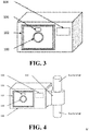
- the embodiments of the present specification provide a schematic diagram of a fare collection device, as shown in FIG. 3 , the fare collection device comprising a first collector 100, a second collector 102, a processor 104 and a sensor 106.
- the first collector 100 is a camera
- the second collector 102 is an NFC loop antenna
- the sensor 106 is a rangefinder located in a region between the camera and the NFC loop antenna for measuring the distance between the target object and the fare collection device.
- FIG. 3 is merely an example provided by the present specification and does not define a particular position of the sensor 106 on the fare collection device.
- the processor 104 may be arranged inside the housing of the fare collection device, which is indicated by a dashed line rectangle.
- the first collector 100 may be in a turned off state by default.
- the processor 104 may activate the first collector 100 and then determine whether the first collector 100 has collected a to-be-recognized image; if so, parse the to-be-recognized image to obtain payment information, and collect a ride fare from the user according to the payment information; if not, activate the second collector 102, and obtain payment information through a near-field non-contact collection process, so as to collect a ride fare from the user.
- the processor 104 may turn off the first collector 100 after determining whether the first collector 100 has collected a to-be-recognized image.
- the determining result comprises: the first collector 100 having collected a to-be-recognized image and the first collector 100 having not collected a to-be-recognized image.
- the processor 104 may turned off the first collector 100 regardless of whether the first collector 100 has collected a to-be-recognized image. For example, if the first collector 100 has collected a to-be-recognized image, there is no need to further collect images through the first collector 100, and the first collector 100 may be turned off. If the first collector 100 has not collected a to-be-recognized image, it can be switched to the second collector 102 to obtain payment information. Similarly, there is also no need to collect an image through the first collector 100, and the first collector 100 may be turned off.
- a to-be-recognized image may be collected using this camera, and the processor 104 may parse the to-be-recognized image to obtain payment information of the user. If this camera has not collected a to-be-recognized image, the processor 104 may switch to the second collector 102 to obtain payment information of the user through a near-field non-contact collection process.
- the second collector 102 may be in a turned off state by default.
- the processor 104 may activate the second collector 102.
- the processor 104 may activate the NFC antenna, so that the NFC antenna broadcasts an NFC excitation signal to terminals in the surroundings.
- the NFC chip in a device of a user for providing payment information receives the NFC excitation signal
- the NFC chip may broadcast an NFC signal carrying the payment information of the user.
- the NFC antenna may receive the NFC signal that is broadcast by the terminal. Therefore, the processor 104 may extract the payment information of the user according to the NFC signal, so as to collect a ride fare from the user.
- the fare collection device can only activate one collector within any period of time to collect payment information of a user.
- the second collector 102 may be turned off or put into sleep; while the first collector 100 may be turned off or put into sleep when the fare collection device currently activates the second collector 102 to collect payment information of the user.
- the reason of the fare collection device only activating one collector within any period of time is that, if the fare collection device activates two (or more) collectors at the same time, the process of payment processing by the user may be affected.
- the second collector 102 may also obtain an NFC signal carrying the payment information of the user that is broadcast by the cell phone.
- the cell phone of the user may correspondingly pop up a page for paying the fare using the NFC function, while this page may cover the page that is used by the user for scanning a code to pay the fare, which may interfere with the process of fare payment by the user through code scanning.
- the second collector 102 may be turned off or put into sleep, and the first collector 100 may be activated.
- the processor 104 may keep the first collector 100 in the turned off state.
- the processor 104 may switch to the second collector 102 to obtain payment information through a near-field non-contact collection process, and then collect the ride fare from the user.
- the fare collection device may collect the payment information in various of collections manners even when the user can only provide the payment information in a single manner. As a result, it is very convenient for the user during the process of paying ride fares.
- the first collector 100 when the first collector 100 is a camera, payment information may not be rapidly recognized even if the user provides a to-be-recognized image (i.e., an image comprising the payment information DOI) in cases where the environment is complex in exemplary application scenarios.
- a to-be-recognized image i.e., an image comprising the payment information DOI
- the ambient light is too dark or too strong, leading to insufficient contrast of the 2-D barcode.
- the processor 104 may wait for a preset duration after triggering the ride fare collection transaction, and then switch to the second collector 102 only after determining that no payment information has been parsed out within the preset duration.
- the processor 104 may determine whether payment information has been obtained within a preset duration after triggering the ride fare collection transaction.
- the particular length of the preset duration is not limited in the present specification and may be set as needed.
- the fare collection device is a fare collection device on a subway turnstile
- the subway company stipulates that a turnstile needs to complete a determination whether to open the turnstile within 300 ms (i.e., the maximum duration of each ride fare collection transaction may not exceed 300 ms).
- the preset duration may be less than 300 ms, e.g., 150 m, so as to reserve a time for the second collector 102 to obtain payment information and for the processor 104 to collect the ride fare from the user.
- the fare collection device may comprise a housing 108 for protecting the fare collection device and a fixing part 110.
- the fixing part 110 may be connected to the housing 108 to fix the fare collection device onto a means of public transport.
- the means of public transport may comprise a bus, a tram, a taxi, and the like.
- the housing 108 may comprise a transparent area so as not to block the camera from collecting an image.
- the second collector 102 is an NFC antenna
- the NFC antenna may be disposed inside the housing 108 so as to protect the NFC antenna, while the material used by the housing 108 may be a material that does not block radio frequency signals emitted by the NFC antenna.
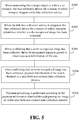
- the present specification provides a fare collection device, comprising a first collector 100, a second collector 102, a processor 104, a sensor 106, a housing 108 and a fixing part 110, as shown in FIG. 4 . It can be seen that the fare collection device is disposed inside the housing 108 for the protection by the housing 108. Moreover, the housing 108 is connected to a bus handrail via the connected fixing part 110 so as to be fixed onto the bus.
- the present specification correspondingly further provides a payment method, as shown in FIG. 5 .
- FIG. 5 is a schematic diagram of a payment flow based on the fare collection device shown in FIG. 1 that is provided by the present specification.
- the method may, for example, comprise the following steps.
- the payment flow may be implemented by the fare collection device shown in FIG. 1 .
- the processor 100 may monitor whether the first collector has collected a to-be-recognized image; when confirming that a to-be-recognized image has been collected, determine payment information by parsing the to-be-recognized image, and then collect a ride fare from the user; when confirming that no to-be-recognized image has been collected, activate the second collector to obtain payment information through a near-field non-contact collection process, and collect a ride fare from the user according to the payment information.
- the fare collection device is a fare collection device on a means of public transport, such as a card reader on a bus.
- the fare collection device may emit a signal via a provided rangefinder to the surroundings to detect whether a target object is approaching the card reader.
- the processor may determine, according to the emitted signal and a signal returned by the user, that a user is approaching the card reader at present, and when determining that the distance between the user and the fare collection device is less than a set distance, determine to trigger a ride fare collection transaction.
- the user may invoke a payment 2-D barcode carrying payment information of the user from a cell phone in his/her hand, and the user may present the payment 2-D barcode displayed on the cell phone interface to the card reader for scanning.
- the fare collection device is provided with a first collector (e.g., a camera) capable of collecting a to-be-recognized image.
- a first collector e.g., a camera
- the camera collects the payment 2-D barcode displayed by the cell phone, such that the processor can parse the payment 2-D barcode.
- the processor successfully obtains payment information of the user by parsing the payment 2-D barcode, the processor can determine a fare to be paid by the user for riding the bus according to the payment information, and execute a corresponding deduction operation.
- the processor may activate a second collector (e.g., an NFC antenna) provided in the fare collection device, here, the NFC antenna is typically in a turned off or sleeping state.
- a second collector e.g., an NFC antenna
- the processor may obtain, via the NFC antenna, an NFC signal carrying the payment information of the user that is broadcast by the terminal, and extract the payment information from the NFC signal. Then, the processor may execute a corresponding deduction operation according to the payment information.
- the NFC antenna may be turned off or put into sleep.
- the above description uses a process of using a card reader on a bus to perform payment processing as an example.
- the deduction operation may be completed when a user swipes a card at the time of getting off the bus.
- the processor may determine to execute a corresponding deduction operation by obtaining the payment information twice (i.e., the payment information obtained by the fare collection device when a passenger gets on the bus, and the payment information obtained when the passenger gets off the bus).
- the manners in which the payment information is obtained in the two times may not be completely the same, and how to particularly execute the deduction operation is not limited in the present specification.
- the fare collection device is a fare collection device on a subway turnstile
- a user presents his/her own payment 2-D barcode to a subway turnstile (a turnstile located at a station where the user enters the subway) when entering a station
- the subway turnstile can obtain payment information of the user by parsing the payment 2-D barcode, and then send the payment information as identification information to a server, such that the server identifies the starting station that the user takes the subway according to the payment information and the subway turnstile that sends the payment information.
- the user When exiting a station, the user may activate the NFC module of the cell phone, to cause a subway turnstile (a turnstile located at a station where the user exits the subway) to obtain an NFC signal broadcast by the user's cell phone, and then extract the payment information of the user from the NFC signal.
- the fare collection device may send the extracted payment information to the server, such that the server determines a fare to be paid by the user for taking the subway according to the payment information and executes a corresponding deduction operation.
- the fare collection device located on the entering station turnstile may collect a to-be-recognized image through a collector when the user enters a station, and then parse the to-be-recognized image to obtain payment information of the user; while the fare collection device located on the exiting station turnstile may collect payment information of the user through another collector when the user exits a station, and execute the deduction operation on the user.
- the first collector and the second collector are relative concepts, and the present specification does not limit the fare collection device to be a particular collector.
- the first collector and the second collector may not be completely the same.
- Collectors and collection manners that can be supported by the fare collection device are not limited only to the above-described two types, but may also be, for example, other manners such as a Bluetooth antenna and Bluetooth payment.
- the fare collection device may support various of collectors.
- an improvement to a technology can be obviously differentiated into a hardware improvement (e.g., an improvement to a circuit structure, such as a diode, a transistor, a switch, etc.) or a software improvement (an improvement to a flow of a method).
- a hardware improvement e.g., an improvement to a circuit structure, such as a diode, a transistor, a switch, etc.
- a software improvement an improvement to a flow of a method.
- PLD Programmable Logic Device
- FPGA Field Programmable Gate Array
- a designer programs on his/her own to "integrate" a digital system onto one piece of PLD, who does not need to request a chip manufacturer to design and manufacture a dedicated IC chip.
- this type of programming has mostly been implemented through “logic compiler” software, rather than manually manufacturing the IC chips.
- the logic compiler software is similar to a software compiler used for program development and writing, while a particular programming language must be used for writing source codes prior to compiling, which is referred to as a Hardware Description Language (HDL).
- HDL Hardware Description Language
- HDL Very-High-Speed Integrated Circuit Hardware Description Language
- ABEL Advanced Boolean Expression Language
- AHDL Altera Hardware Description Language
- HDCal JHDL
- Java Hardware Description Language Lava, Lola, MyHDL
- PALASM RHDL
- VHDL Very-High-Speed Integrated Circuit Hardware Description Language
- Verilog Verilog
- a controller may be implemented in any proper manner.
- a controller may be in, for example, a form of a microprocessor or processor, as well as a computer readable medium that stores computer readable program codes (e.g., software or firmware) capable of being executed by the (micro) processor, a logic gate, a switch, an Application Specific Integrated Circuit (ASIC), a programmable logic controller, and an embedded microcontroller.
- Examples of the controller include, but are not limited to, the following microcontrollers: ARC 625D, Atmel AT91SAM, Microchip PIC18F26K20, and Silicone Labs C8051F320.
- a memory controller may further be implemented as a part of control logic of a memory.
- controller may be deemed as a hardware part, while devices comprised in the controller and configured to achieve various functions may also be deemed as a structure inside the hardware part. Alternatively, devices configured to achieve various functions may even be deemed as both software modules to implement a method and a structure inside a hardware part.
- a computer may be, for example, a personal computer, a laptop computer, a cellular phone, a camera phone, a smart phone, a personal digital assistant, a medium player, a navigation device, an email device, a game console, a tablet computer, a wearable device, or a combination of any devices in these devices.
- the above device is divided into various units according to functions for description. Functions of the units may be implemented in one or more pieces of software and/or hardware when the present application is implemented.
- the embodiments of the present invention may be provided as a method, a system, or a computer program product. Therefore, the present invention may be implemented as a complete hardware embodiment, a complete software embodiment, or an embodiment combing software and hardware. Moreover, the present invention may be in the form of a computer program product implemented on one or more computer usable storage media (including, but not limited to, a magnetic disk memory, CD-ROM, an optical memory, etc.) comprising computer usable program codes.
- a computer usable storage media including, but not limited to, a magnetic disk memory, CD-ROM, an optical memory, etc.
- These computer program instructions may be provided for a general-purpose computer, a special-purpose computer, an embedded processor, or a processor of other programmable data processing devices to generate a machine, causing the instructions executed by a computer or a processor of other programmable data processing devices to generate an apparatus for implementing a function specified in one or more processes in the flowcharts and/or in one or more blocks in the block diagrams.
- These computer program instructions may also be stored in a computer readable memory that can instruct a computer or other programmable data processing devices to work in a particular manner, causing the instructions stored in the computer readable memory to generate a manufactured article that includes an instruction apparatus.
- the instruction apparatus implements a function specified in one or more processes in the flowcharts and/or in one or more blocks in the block diagrams.
- These computer program instructions may also be loaded onto a computer or other programmable data processing devices, causing a series of operational steps to be performed on the computer or other programmable devices, thereby generating computer-implemented processing. Therefore, the instructions executed on the computer or other programmable devices provide steps for implementing a function specified in one or more processes in the flowcharts and/or in one or more blocks in the block diagrams.
- the computation device includes one or more processors (CPUs), input/output interfaces, network interfaces, and a memory.
- the memory may include computer readable media, such as a volatile memory, a Random-Access Memory (RAM), and/or a non-volatile memory, e.g., a Read-Only Memory (ROM) or a flash RAM.
- RAM Random-Access Memory
- ROM Read-Only Memory
- the memory is an example of a computer readable medium.
- Computer readable media include permanent, volatile, mobile, and immobile media, which can implement information storage through any method or technology.
- the information may be computer readable instructions, data structures, program modules, or other data.
- Examples of storage media of computers include, but are not limited to, Phase-change Random Access Memories (PRAMs), Static Random Access Memories (SRAMs), Dynamic Random Access Memories (DRAMs), other types of Random Access Memories (RAMs), Read-Only Memories (ROMs), Electrically Erasable Programmable Read-Only Memories (EEPROMs), flash memories or other memory technologies, Compact Disk Read-Only Memories (CD-ROMs), Digital Versatile Discs (DVDs) or other optical memories, magnetic cassettes, cassette and disk memories or other magnetic memory devices, or any other non-transmission media, which can be used for storing information accessible to a computation device.
- the computer readable media do not include transitory media, such as modulated data signals and carriers.
- the embodiments of the present application may be provided as a method, a system, or a computer program product. Therefore, the present application may be implemented as a complete hardware embodiment, a complete software embodiment, or an embodiment combing software and hardware. Moreover, the present application may be in the form of a computer program product implemented on one or more computer usable storage media (including, but not limited to, a magnetic disk memory, CD-ROM, an optical memory, etc.) comprising computer usable program codes.
- a computer usable storage media including, but not limited to, a magnetic disk memory, CD-ROM, an optical memory, etc.
- the present application may be described in a regular context of a computer executable instruction that is executed by a computer, such as a program module.
- the program module comprises a routine, a program, an object, a component, a data structure, etc. for executing a particular task or implementing a particular abstract data type.
- the present application may also be practiced in distributed computing environments. In these distributed computing environments, remote processing devices connected via communication networks carry out tasks.
- a program module may be located in local and remote computer storage media, including storage devices.
Landscapes
- Business, Economics & Management (AREA)
- Engineering & Computer Science (AREA)
- Physics & Mathematics (AREA)
- General Physics & Mathematics (AREA)
- Theoretical Computer Science (AREA)
- Accounting & Taxation (AREA)
- Computer Networks & Wireless Communication (AREA)
- Strategic Management (AREA)
- General Business, Economics & Management (AREA)
- Finance (AREA)
- Computer Vision & Pattern Recognition (AREA)
- Devices For Checking Fares Or Tickets At Control Points (AREA)
Applications Claiming Priority (2)
| Application Number | Priority Date | Filing Date | Title |
|---|---|---|---|
| CN201711070469.2A CN107978022B (zh) | 2017-11-03 | 2017-11-03 | 一种公共交通工具的收款设备 |
| PCT/CN2018/102739 WO2019085613A1 (zh) | 2017-11-03 | 2018-08-28 | 一种公共交通工具的收款设备 |
Publications (2)
| Publication Number | Publication Date |
|---|---|
| EP3678078A1 true EP3678078A1 (de) | 2020-07-08 |
| EP3678078A4 EP3678078A4 (de) | 2020-07-15 |
Family
ID=62013000
Family Applications (1)
| Application Number | Title | Priority Date | Filing Date |
|---|---|---|---|
| EP18873661.5A Withdrawn EP3678078A4 (de) | 2017-11-03 | 2018-08-28 | Fahrpreiseinsammelvorrichtung für öffentliche verkehrsmittel |
Country Status (8)
| Country | Link |
|---|---|
| US (1) | US11004060B2 (de) |
| EP (1) | EP3678078A4 (de) |
| CN (1) | CN107978022B (de) |
| MY (1) | MY204505A (de) |
| PH (1) | PH12020550497A1 (de) |
| SG (1) | SG11202003777PA (de) |
| TW (1) | TWI688910B (de) |
| WO (1) | WO2019085613A1 (de) |
Families Citing this family (12)
| Publication number | Priority date | Publication date | Assignee | Title |
|---|---|---|---|---|
| CN107978022B (zh) | 2017-11-03 | 2019-10-25 | 阿里巴巴集团控股有限公司 | 一种公共交通工具的收款设备 |
| CN108932616B (zh) * | 2018-06-21 | 2021-12-07 | 上海旺链信息科技有限公司 | 电子通行通道支付切换平台 |
| CN109426746A (zh) * | 2018-08-03 | 2019-03-05 | 中国银联股份有限公司 | 扫码枪装置以及非接受理和扫码读取的切换控制方法 |
| CN109472175B (zh) * | 2018-08-21 | 2022-08-16 | 中国银联股份有限公司 | 电磁感应装置以及受理终端及其切换控制方法 |
| CN109118598A (zh) * | 2018-08-29 | 2019-01-01 | 合肥浮点信息科技有限公司 | 一种具有二维码支付功能的公共交通消费终端设备 |
| CN110517033B (zh) * | 2019-08-28 | 2025-03-07 | 腾讯科技(深圳)有限公司 | 一种快速扫描支付方法及装置 |
| CN110570185B (zh) * | 2019-09-03 | 2024-03-26 | 腾讯科技(深圳)有限公司 | 资源转移方法、装置、存储介质及电子设备 |
| CN112090799A (zh) * | 2020-09-08 | 2020-12-18 | 长丰大成信息科技有限公司 | 一种无人巴士用支付感应装置及控制方法 |
| CA3140652A1 (en) * | 2020-11-30 | 2022-05-30 | Multiwave Sensors Inc. | Camera in bracket and method to minimize blind spots to the transmission of antenna signals |
| CN113344571A (zh) * | 2021-06-23 | 2021-09-03 | 支付宝(杭州)信息技术有限公司 | 一种支付方法、装置及设备 |
| CN113840279B (zh) * | 2021-09-22 | 2024-05-14 | Oppo广东移动通信有限公司 | 模拟卡激活方法、装置、终端和存储介质 |
| CN118586912B (zh) * | 2024-08-02 | 2025-02-18 | 支付宝(杭州)信息技术有限公司 | 支付方法、设备及存储介质 |
Family Cites Families (37)
| Publication number | Priority date | Publication date | Assignee | Title |
|---|---|---|---|---|
| US6415978B1 (en) * | 1999-05-03 | 2002-07-09 | Psc Scanning, Inc. | Multiple technology data reader for bar code labels and RFID tags |
| CN1316415C (zh) | 2001-05-14 | 2007-05-16 | 库比克公司 | 使用网络的自动票费收集设备的系统实现 |
| JP2007047960A (ja) * | 2005-08-09 | 2007-02-22 | Nippon Signal Co Ltd:The | 媒体処理装置及びそれを用いた自動改札機 |
| US20070205279A1 (en) | 2006-03-03 | 2007-09-06 | Ge Security, Inc. | Integrated explosives detector and transit fare collection system and method |
| US20080203170A1 (en) | 2007-02-28 | 2008-08-28 | Visa U.S.A. Inc. | Fraud prevention for transit fare collection |
| US7527208B2 (en) | 2006-12-04 | 2009-05-05 | Visa U.S.A. Inc. | Bank issued contactless payment card used in transit fare collection |
| US8118223B2 (en) | 2006-09-28 | 2012-02-21 | Visa U.S.A. Inc. | Smart sign mobile transit fare payment |
| EP2128809A1 (de) * | 2008-05-30 | 2009-12-02 | Luc Stals | Servervorrichtung zur Steuerung einer Transaktion, erste und zweite Einheit |
| US20100082445A1 (en) * | 2008-09-30 | 2010-04-01 | Apple Inc. | Smart menu options |
| DE202009003939U1 (de) * | 2009-03-23 | 2009-06-25 | Skidata Ag | Leseeinrichtung für eine Zugangskontrollvorrichtung |
| SG187866A1 (en) * | 2010-09-08 | 2013-03-28 | Bilcare Technologies Singapore Pte Ltd | An integrated unit for reading identification information based on inherent disorder |
| CA2726781A1 (en) | 2010-12-29 | 2012-06-29 | Evgeny Lishak | Methods of offline fare collection for open-loop and hybrid card systems |
| CN201965675U (zh) * | 2011-01-11 | 2011-09-07 | 武汉大学 | 一种无停留地铁付费系统 |
| US9473295B2 (en) * | 2011-09-26 | 2016-10-18 | Cubic Corporation | Virtual transportation point of sale |
| WO2013184046A1 (en) * | 2012-06-07 | 2013-12-12 | Unwire Aps | One stop validation device |
| US20140015978A1 (en) * | 2012-07-16 | 2014-01-16 | Cubic Corporation | Barrierless gate |
| JP5398899B2 (ja) * | 2012-12-14 | 2014-01-29 | 株式会社東芝 | 読取り装置 |
| US9741177B2 (en) | 2013-05-30 | 2017-08-22 | Haroldo J. Montealegre | Transit fare collection system |
| US9603090B2 (en) * | 2013-08-08 | 2017-03-21 | Apple Inc. | Management of near field communications using low power modes of an electronic device |
| AU2015253029A1 (en) * | 2014-04-30 | 2016-11-10 | Cubic Corporation | Fare evasion detection using video analytics |
| CN105099692B (zh) * | 2014-05-22 | 2020-01-14 | 创新先进技术有限公司 | 安全校验方法、装置、服务器及终端 |
| US20160019726A1 (en) | 2014-07-16 | 2016-01-21 | Spx Corporation | Fare collecting apparatus and method having wireless communication ability |
| US20160019727A1 (en) | 2014-07-16 | 2016-01-21 | Spx Corporation | Transit Authority Fare Administration and Management System |
| WO2016012994A1 (en) | 2014-07-23 | 2016-01-28 | Adom Intelligent Transport Ltd | Method and system for fare collection and validation on a transportation network |
| US9275535B1 (en) * | 2014-08-11 | 2016-03-01 | Cubic Corporation | Detecting and identifying fare evasion at an access control point |
| US9501768B2 (en) * | 2014-08-11 | 2016-11-22 | Cubic Corporation | Smart ticketing in fare collection systems |
| US10282920B2 (en) | 2015-06-19 | 2019-05-07 | Cubic Corporation | RFID for fare collection |
| US9972149B2 (en) * | 2015-08-24 | 2018-05-15 | Cubic Corporation | Vision-based fare collection |
| CN105719133A (zh) * | 2016-01-25 | 2016-06-29 | 张福生 | 一种多功能车载pos机系统及其自适应的工作方法 |
| CN105926486A (zh) * | 2016-04-15 | 2016-09-07 | 广东工业大学 | 一种支持扫码支付的地铁闸门装置 |
| CN205959313U (zh) * | 2016-08-05 | 2017-02-15 | 深圳市智微智能科技开发有限公司 | 一种非接触受理和扫码读取二合一的金融支付装置 |
| CN206162792U (zh) * | 2016-11-07 | 2017-05-10 | 谢忠 | 一种用于公交系统的带扫描功能的读卡器 |
| US9741178B1 (en) | 2016-12-14 | 2017-08-22 | Conduent Business Services, Llc | Fare collection system in a public transit network |
| US11120641B2 (en) | 2016-12-14 | 2021-09-14 | Conduent Business Services, Llc | System for public transit fare collection, decomposition and display |
| CN106548443A (zh) * | 2017-01-09 | 2017-03-29 | 区绮云 | 一种新型的交通工具自助购票验票软件 |
| US20190095836A1 (en) | 2017-09-22 | 2019-03-28 | Conduent Business Services, Llc | Prediction of actual loads from fare collection data |
| CN107978022B (zh) * | 2017-11-03 | 2019-10-25 | 阿里巴巴集团控股有限公司 | 一种公共交通工具的收款设备 |
-
2017
- 2017-11-03 CN CN201711070469.2A patent/CN107978022B/zh active Active
-
2018
- 2018-08-28 SG SG11202003777PA patent/SG11202003777PA/en unknown
- 2018-08-28 MY MYPI2020002069A patent/MY204505A/en unknown
- 2018-08-28 WO PCT/CN2018/102739 patent/WO2019085613A1/zh not_active Ceased
- 2018-08-28 EP EP18873661.5A patent/EP3678078A4/de not_active Withdrawn
- 2018-09-03 TW TW107130828A patent/TWI688910B/zh not_active IP Right Cessation
-
2020
- 2020-01-17 US US16/745,657 patent/US11004060B2/en active Active
- 2020-04-27 PH PH12020550497A patent/PH12020550497A1/en unknown
Also Published As
| Publication number | Publication date |
|---|---|
| TWI688910B (zh) | 2020-03-21 |
| WO2019085613A1 (zh) | 2019-05-09 |
| US20200151705A1 (en) | 2020-05-14 |
| CN107978022A (zh) | 2018-05-01 |
| US11004060B2 (en) | 2021-05-11 |
| PH12020550497A1 (en) | 2021-04-26 |
| CN107978022B (zh) | 2019-10-25 |
| SG11202003777PA (en) | 2020-05-28 |
| TW201918948A (zh) | 2019-05-16 |
| MY204505A (en) | 2024-08-30 |
| EP3678078A4 (de) | 2020-07-15 |
Similar Documents
| Publication | Publication Date | Title |
|---|---|---|
| US11004060B2 (en) | Fare collection device for means of public transport | |
| US11468445B2 (en) | Service processing method, device, and system | |
| TWI713891B (zh) | 一種公共交通支付的方法、裝置及設備 | |
| US10831740B2 (en) | Parallel processing of service data corresponding to multiple target objects | |
| US10891609B2 (en) | Transaction card and information displaying method | |
| EP3716141A1 (de) | Identitätsauthentifizierungsverfahren,- system, -vorrichtung und -einrichtung | |
| US20200126089A1 (en) | Settlement method, entrance control method, and apparatus | |
| CN108830605B (zh) | 一种移动支付方法、装置及支付系统 | |
| CN113240428B (zh) | 支付处理方法及装置 | |
| WO2019179247A1 (zh) | 一种支付辅助终端 | |
| TW202121326A (zh) | 用車支付方法、裝置、系統及電子設備 | |
| WO2025077652A1 (zh) | 一种支付方法、装置以及设备 | |
| WO2019137357A1 (zh) | 付款码获取、支付请求响应方法、装置以及设备 | |
| KR20130043910A (ko) | 이동 단말기 및 그 제어방법, 이를 위한 기록매체 | |
| CN112837053B (zh) | 支付处理方法及装置 | |
| KR200485409Y1 (ko) | 음성인식과 제스처를 이용하는 주차관리 휴대 단말기 | |
| CN114444527B (zh) | 一种扫码识别方法、装置、设备及介质 | |
| HK1253992B (zh) | 一种公共交通工具的收款设备 | |
| US11250392B2 (en) | Data processing methods, apparatuses, and terminal devices | |
| HK1253992A1 (zh) | 一种公共交通工具的收款设备 | |
| HK1253981A1 (zh) | 一种公共交通支付的方法、装置及设备 | |
| US20260111869A1 (en) | Intelligent wearable device NFC service processing methods, apparatuses, and devices | |
| CN121391253A (zh) | 支付处理方法、装置以及设备 |
Legal Events
| Date | Code | Title | Description |
|---|---|---|---|
| STAA | Information on the status of an ep patent application or granted ep patent |
Free format text: STATUS: THE INTERNATIONAL PUBLICATION HAS BEEN MADE |
|
| PUAI | Public reference made under article 153(3) epc to a published international application that has entered the european phase |
Free format text: ORIGINAL CODE: 0009012 |
|
| STAA | Information on the status of an ep patent application or granted ep patent |
Free format text: STATUS: REQUEST FOR EXAMINATION WAS MADE |
|
| 17P | Request for examination filed |
Effective date: 20200401 |
|
| AK | Designated contracting states |
Kind code of ref document: A1 Designated state(s): AL AT BE BG CH CY CZ DE DK EE ES FI FR GB GR HR HU IE IS IT LI LT LU LV MC MK MT NL NO PL PT RO RS SE SI SK SM TR |
|
| AX | Request for extension of the european patent |
Extension state: BA ME |
|
| A4 | Supplementary search report drawn up and despatched |
Effective date: 20200616 |
|
| RIC1 | Information provided on ipc code assigned before grant |
Ipc: G07B 15/06 20110101ALI20200609BHEP Ipc: G06Q 20/32 20120101ALI20200609BHEP Ipc: G06Q 20/00 20120101AFI20200609BHEP Ipc: G06Q 20/18 20120101ALI20200609BHEP Ipc: G07G 1/12 20060101ALI20200609BHEP Ipc: G07B 15/00 20110101ALI20200609BHEP |
|
| RAP1 | Party data changed (applicant data changed or rights of an application transferred) |
Owner name: ADVANCED NEW TECHNOLOGIES CO., LTD. |
|
| DAV | Request for validation of the european patent (deleted) | ||
| DAX | Request for extension of the european patent (deleted) | ||
| STAA | Information on the status of an ep patent application or granted ep patent |
Free format text: STATUS: EXAMINATION IS IN PROGRESS |
|
| 17Q | First examination report despatched |
Effective date: 20210223 |
|
| STAA | Information on the status of an ep patent application or granted ep patent |
Free format text: STATUS: THE APPLICATION HAS BEEN WITHDRAWN |
|
| 18W | Application withdrawn |
Effective date: 20220211 |