EP3677984A1 - Method of time delivery in a computing system and system thereof - Google Patents
Method of time delivery in a computing system and system thereof Download PDFInfo
- Publication number
- EP3677984A1 EP3677984A1 EP19150556.9A EP19150556A EP3677984A1 EP 3677984 A1 EP3677984 A1 EP 3677984A1 EP 19150556 A EP19150556 A EP 19150556A EP 3677984 A1 EP3677984 A1 EP 3677984A1
- Authority
- EP
- European Patent Office
- Prior art keywords
- time
- system time
- priority
- delivery
- priorities
- Prior art date
- Legal status (The legal status is an assumption and is not a legal conclusion. Google has not performed a legal analysis and makes no representation as to the accuracy of the status listed.)
- Granted
Links
- 238000000034 method Methods 0.000 title claims abstract description 36
- 230000004044 response Effects 0.000 claims abstract description 22
- 238000012937 correction Methods 0.000 claims abstract description 12
- 230000001934 delay Effects 0.000 claims abstract description 5
- 238000012360 testing method Methods 0.000 claims description 19
- 238000005259 measurement Methods 0.000 claims description 11
- 238000012545 processing Methods 0.000 claims description 6
- 238000010200 validation analysis Methods 0.000 claims description 5
- 238000004590 computer program Methods 0.000 claims description 4
- 230000003068 static effect Effects 0.000 claims description 3
- 239000000523 sample Substances 0.000 claims description 2
- 230000000977 initiatory effect Effects 0.000 claims 1
- 238000012546 transfer Methods 0.000 description 5
- 238000010586 diagram Methods 0.000 description 4
- 230000009471 action Effects 0.000 description 2
- 238000004364 calculation method Methods 0.000 description 2
- 230000008569 process Effects 0.000 description 2
- 108700009949 PTP protocol Proteins 0.000 description 1
- 238000004458 analytical method Methods 0.000 description 1
- 238000001914 filtration Methods 0.000 description 1
- 230000006870 function Effects 0.000 description 1
- 238000007726 management method Methods 0.000 description 1
- 238000012986 modification Methods 0.000 description 1
- 230000004048 modification Effects 0.000 description 1
- 230000001902 propagating effect Effects 0.000 description 1
- 238000011084 recovery Methods 0.000 description 1
- 230000001360 synchronised effect Effects 0.000 description 1
- 239000011800 void material Substances 0.000 description 1
Images


Classifications
-
- G—PHYSICS
- G06—COMPUTING; CALCULATING OR COUNTING
- G06F—ELECTRIC DIGITAL DATA PROCESSING
- G06F1/00—Details not covered by groups G06F3/00 - G06F13/00 and G06F21/00
- G06F1/04—Generating or distributing clock signals or signals derived directly therefrom
-
- G—PHYSICS
- G06—COMPUTING; CALCULATING OR COUNTING
- G06F—ELECTRIC DIGITAL DATA PROCESSING
- G06F1/00—Details not covered by groups G06F3/00 - G06F13/00 and G06F21/00
- G06F1/04—Generating or distributing clock signals or signals derived directly therefrom
- G06F1/14—Time supervision arrangements, e.g. real time clock
-
- G—PHYSICS
- G06—COMPUTING; CALCULATING OR COUNTING
- G06F—ELECTRIC DIGITAL DATA PROCESSING
- G06F11/00—Error detection; Error correction; Monitoring
- G06F11/07—Responding to the occurrence of a fault, e.g. fault tolerance
- G06F11/16—Error detection or correction of the data by redundancy in hardware
- G06F11/1675—Temporal synchronisation or re-synchronisation of redundant processing components
-
- G—PHYSICS
- G06—COMPUTING; CALCULATING OR COUNTING
- G06F—ELECTRIC DIGITAL DATA PROCESSING
- G06F15/00—Digital computers in general; Data processing equipment in general
- G06F15/16—Combinations of two or more digital computers each having at least an arithmetic unit, a program unit and a register, e.g. for a simultaneous processing of several programs
- G06F15/163—Interprocessor communication
- G06F15/173—Interprocessor communication using an interconnection network, e.g. matrix, shuffle, pyramid, star, snowflake
- G06F15/17306—Intercommunication techniques
- G06F15/17325—Synchronisation; Hardware support therefor
-
- G—PHYSICS
- G06—COMPUTING; CALCULATING OR COUNTING
- G06F—ELECTRIC DIGITAL DATA PROCESSING
- G06F9/00—Arrangements for program control, e.g. control units
- G06F9/06—Arrangements for program control, e.g. control units using stored programs, i.e. using an internal store of processing equipment to receive or retain programs
- G06F9/46—Multiprogramming arrangements
- G06F9/466—Transaction processing
-
- G—PHYSICS
- G06—COMPUTING; CALCULATING OR COUNTING
- G06F—ELECTRIC DIGITAL DATA PROCESSING
- G06F9/00—Arrangements for program control, e.g. control units
- G06F9/06—Arrangements for program control, e.g. control units using stored programs, i.e. using an internal store of processing equipment to receive or retain programs
- G06F9/46—Multiprogramming arrangements
- G06F9/54—Interprogram communication
- G06F9/545—Interprogram communication where tasks reside in different layers, e.g. user- and kernel-space
-
- H—ELECTRICITY
- H04—ELECTRIC COMMUNICATION TECHNIQUE
- H04J—MULTIPLEX COMMUNICATION
- H04J3/00—Time-division multiplex systems
- H04J3/02—Details
- H04J3/06—Synchronising arrangements
- H04J3/0635—Clock or time synchronisation in a network
- H04J3/0638—Clock or time synchronisation among nodes; Internode synchronisation
- H04J3/0658—Clock or time synchronisation among packet nodes
- H04J3/0661—Clock or time synchronisation among packet nodes using timestamps
- H04J3/0667—Bidirectional timestamps, e.g. NTP or PTP for compensation of clock drift and for compensation of propagation delays
Definitions
- the presently disclosed subject matter relates to the field of computing systems and, more particularly, to delivering accurate time to computer-implemented applications.
- Time transfer protocols as, for example, IEEE 1588 Precision Time Protocol (PTP) and Network Time Protocol (NTP).
- T ERR TE TP + TE TP 2 S + TE S 2 C , where:
- the inventors recognized that known techniques, while enabling successful time recovery, do not address the problem of improving accuracy of delivering the recovered time to respective applications.
- a method of time delivery in a computer system comprising a system call interface (SCI) located in a kernel space and operatively connected to a time client located in a user space.
- the method comprises: a. using a time agent component located in the user space to measure data indicative of delay in a system time delivery and to derive therefrom a system time delivery error TE S2C ; b. using the system time delivery error TE S2C to enable correction of system time thereby giving rise to a corrected system time; c. sending by the SCI the corrected system time in response to a "Read Clock RT" call received from the time client.
- SCI system call interface
- Operations a) - c) can be repeated periodically and/or initiated responsive to one or more predefined events.
- enabling correction of system time can comprise: calculating by the time agent component a corrected system time in accordance with the the system time delivery error TES2C; and sending the corrected system time to the SCI as a value in a time setting command.
- the method can further comprise: using the time agent component to measure data indicative of delays in the system time delivery for "Read Clock RT" calls with different priorities of a plurality of priorities, and to respectively obtain a set of data indicative of priority-based system time delivery errors TES2C corresponding to respective priorities of the plurality of priorities; in response to a system time request received from the time client, recognizing priority thereof and providing the time client with system time corrected per system time delivery error corresponding to the recognized priority.
- Obtaining the set of system time delivery errors TE S2C can comprise providing operations d) - f) separately for each priority of the plurality of priorities.
- the set of data indicative of priority-based system time delivery errors can comprise at least one of: for each priority of the plurality of priorities, the last calculated TE S2C ; differences between the last calculated TE S2C for the highest priority and the last calculated TE S2C for each of the lower priorities; for each priority of the plurality of priorities, differences between the last calculated TE S2C and the previously calculated TE S2C ; for each priority of the plurality of priorities, system time t rt lastly corrected in accordance with TE S2C corresponding to respective priority.
- the set of data indicative of priority-based system time delivery errors can be maintained by the time agent component in a data structure located in the kernel space and accessible to the SCI.
- SCI in response to the system time request, can obtain from the data structure the data indicative of system delivery error corresponding to the recognized priority, and calculate the corrected system time accordingly.
- the corrected system time can be provided in accordance with policy marking recognizable by SCI.
- the method can further comprise: g. upon disabling CPU interrupts, running a test application performing a loop of a fixed length and determining a loop time TL; h. comparing the obtained value of loop time with one or more values of loop time determined in one or more previous runs of the test application; and i. using the determined discrepancy between the values to steer relative frequencies of time sources in a central processing unit and a network interface card comprised in the computing system.
- operations a) - c) and/or g) - i) can be provided responsive to results of validation.
- the validation can comprise: exchanging, by the time agent component, PTP sync messages with an external probe device with a precise reference; and registering respective PTP timestamps thereby obtaining measurement results indicative of time errors, wherein static time errors are indicative of system time delivery errors and dynamic time errors are indicative of discrepancy of frequency shift.
- the method can comprise one or more of aspects listed above, in any desired combination or permutation which is technically possible.
- a computing system configured to operate in accordance with any technically possible combination or permutation of the above aspects of the method of time delivery.
- a computer program product implemented on a non-transitory computer usable medium and comprising computer readable program code for performing any technically possible combination or permutation of the above aspects of the method of time delivery.
- computer should be expansively construed to cover any kind of hardware-based electronic device with data processing capabilities including, by way of non-limiting example, the computing system disclosed in the present application.
- non-transitory memory and “non-transitory storage medium” used herein should be expansively construed to cover any volatile or non-volatile computer memory suitable to the presently disclosed subject matter.
- clock should be expansively construed to cover any kind of circuitry comprising any appropriate combination of software, firmware and/or hardware and capable to produce a time or frequency signal (e.g. an electrical signal, a value in a register, a value in a network packet, etc.). It is to be understood that the term “signal” used herein excludes transitory propagating signals, but includes any other signal suitable to the presently disclosed subject matter.
- Embodiments of the presently disclosed subject matter are not described with reference to any particular programming language. It will be appreciated that a variety of programming languages can be used to implement the teachings of the presently disclosed subject matter as described herein.
- FIG. 1 schematically illustrating a functional block diagram of a computing system configured in accordance with certain embodiments of the presently disclosed subject matter.
- Computing system 100 comprises a kernel space 101 configured to execute privileged OS functions and operatively connected user space 102 configured to execute one or more user programs.
- User space programs are restricted from direct access to the computing system's resources, and access is handled by the operating system on behalf of the user's programs.
- the user space programs typically communicate with the OS through system calls.
- Operating system is configured to run on a central processing circuitry (CPU), not illustrated separately.
- CPU further comprises a real-time clock 104 (referred to hereinafter as Clock RT) configured to serve as a time source for one or more time clients 107 (denoted as 107-1 - 107-3 ) executable by the computing system.
- Clock RT driver is a part of kernel 101.
- time client should be expansively construed to cover any kind of user program running on the computing system 100 and configured to obtain time from OS with the help of system command(s).
- Time values provided by the OS are referred to hereinafter also as system time.
- OS is configured to receive system time requests from TCs, responsively derive system time from Clock RT 104 and provide the respective values to the time clients via System Call Interface 103.
- time clients can also run in a virtual environment emulated in the computing system and, optionally (e.g. when running on a virtual machine), can obtain system time via virtual OS emulated in the computing system.
- Linux OS For purpose of illustration only, the following description is provided for Linux OS. Those skilled in the art will readily appreciate that the teachings of the presently disclosed subject matter are, likewise, applicable to Windows OS or any other operational system supporting a real-time clock capable of serving as a clock source for the time clients.
- Clock RT 104 can be implemented in different ways known in the art.
- Clock RT 104 can comprise a Time Stamp Counter (TSC).
- TSC is a register counter typically running at the frequency of the CPU and driven by the same oscillator that is used to generate the clock pulses that drive the CPU. TSC starts running when the computing system boots. It is noted that in a multicore CPU, each core can have its own counter being a part of the clock RT. TSC can keep all counters synchronized across all cores in the computing system. Further, TSC can be configured to keep the counters running at a fixed rate regardless of changes in CPU frequency.
- Clock RT 104 can be further operatively connected to a Master Clock 106 that can provide Clock RT with external accurate time with the help of PTP, NTP or other suitable timing protocol.
- the synchronization process can be provided, for example, with the help of Linux PTP daemon.
- System Call Interface (SCI) 103 is configured to derive system time from Clock RT 104. SCI is further configured to provide system time to the TCs in response to clock_gettime(CLOCK_REALTIME) call or any other appropriate command received from a time client.
- a command triggering SCI 103 to derive system time from Clock RT 104 and further deliver the obtained value to the time client is referred to hereinafter as "Read Clock RT" call.
- Time agent component 105 e.g. a user program
- OS e.g. a user program
- OS e.g. a user program
- corrections of system time e.g. with root privilege
- time agent component can be implemented in any appropriate combination of software, firmware and/or hardware as one or more time clients operating in conjunction with OS.
- time client 107 sends ( 201 ) to SCI 103 a "Read clock RT" call.
- SCI receives the call at point-in-time t1 , sends ( 202 ) the respective request to Clock RT 104 and obtains ( 203 ) system time t1 rt provided by Clock RT at point-in-time t2 substantially equal to t1 rt .
- SCI further sends ( 204 ) the system time tlrt to time client 107 which, respectively, receives system time tlrt at point-in-time t3 .
- the difference ( t0 - t2 ) between time of issuing "Read Clock RT" call by a given TC and system time tlrt provided in the response is referred to hereinafter as a system time delivery error TE S2C .
- TE S2C can vary depending on CPU load, call priority, etc.
- Fig. 3 illustrates a generalized flow chart of compensating the TE S2C .
- time agent component continuously measures ( 301 ) data indicative of delay in time delivery and calculates ( 302 ) time error TE S2C .
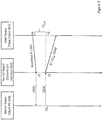
- Fig. 4 illustrates a non-limiting example of measuring delay usable for TE S2C calculation.
- the calls are configured with the highest priority (e.g. as real-time calls) so that the delay (t1-t1 RT ) between time t1 of receiving the call by SCI and system time t1 RT respectively obtained by SCI can be considered as negligible compared with the total TE S2C error.
- the number of cycles N can be configured between one-digit and two-digits so to enable statistical accuracy whilst keeping negligible impact on SCI and Clock RT load.
- the duration of measurement can be configured in a range of few milliseconds, and the measurements (and respective TE S2C calculation) can be configured to be provided every 100 seconds.
- time agent component 105 calculates data indicative of the last calculated TE S2C to calculate the corrected system time. Further, being configured with root privilege, time agent component 105 sends the corrected system time to the SCI as a value in a time setting command (e.g. clock_settime command) to provide SCI with corrected system time, and, thus, to enable ( 303 ) system time correction. SCI sends ( 304 ) the corrected system time in response to a read clock RT call received from a given TC.
- a time setting command e.g. clock_settime command
- correcting the system time after each next measurement cycle can be provided using the difference between the last calculated TE S2C and the previously calculated TE S2C .
- a currently calculated TE S2C can be applied for correcting system time to be delivered to any TC that issues a "Read Clock RT" call between calculating the currently calculated TE S2C and the next TE S2C .
- different time clients can have different priorities for processing, including priority for reading the system time. Consequently, although correcting system time, as detailed above, can improve accuracy of system time delivery to low priority TCs, nevertheless, it will not compensate the respective entire error in system time delivery thereto. In accordance with certain embodiments of the presently disclosed subject matter, compensating the error in system time delivered to a given TC can be provided in accordance with its priority.
- the time agent component can be configured to continuously measure ( 501 ) data indicative of delays in system time delivered to TCs with different priorities, and to use ( 502 ) the measured data to continuously calculate system time delivery errors for TCs with different priorities.
- Fig. 6 illustrates a generalized functional block diagram of the computing system of Fig. 1 further configured to enable priority-based compensating the system time delivery error.
- time agent component 105 can be further configured to issue "Read Clock RT" calls with different priorities and, thus, to provide operations 301-302 separately for each of the relevant priorities, thereby obtaining data indicative of TE S2C per each priority.
- Data indicative of TE S2C can be at least one of: the last calculated TE S2C for each of priorities; differences between the last calculated TE S2C for the highest priority and the last calculated TE S2C for each of the lower priorities; differences between the last calculated TE S2C and the previously calculated TE S2C for each of the priorities, the lastly corrected, for each of the priorities system time t rt , etc.
- Such data can be maintained by time agent component 105 in a priority data structure (PDS) 601 (e.g. a look-up table organized in accordance with priorities) located in kernel space 101 and operatively connected to SCI 103.
- PDS priority data structure
- SCI 103 can be configured to recognize a priority corresponding to a received "Read Clock RT" call.
- SCI can be further configured to comprise a plug-in component 602 configured to obtain, responsive to the "Read Clock RT" call, data from PDS 601 and to set for SCI system time corrected in accordance with call priority recognized by SCI 103 and with respectively obtained data.
- the corrected time can be calculated (at least for lower-priority time clients) by plug-in component 602 in accordance with priority-based TE S2C errors provided by time agent component 105 and stored in PDS 601.
- SCI recognizes ( 503 ) priority of the given TC and uses, with the help of plug-in component 602, the data in PDS 601 to provide ( 504 ) the given TC with system time corrected per system time delivery error corresponding to the recognized priority.
- time agent component 105 can be configured to store in PDC 601 priority-based data indicative of TE S2C for all priorities of a plurality of relevant (e.g. predefined) priorities, and plug-in component 602 can be configured to provide, respectively, corrected system time to SCI for all "Read Clock RT" calls corresponding to the priority of the plurality relevant priorities. It is noted that for "Read Clock RT" calls (if any) with priorities other than of the plurality of relevant priorities, SCI 103 provides system time as received from the Clock RT.
- time agent component 105 and SCI 103 can operate in a manner detailed with reference to Fig. 3 , and plug-in-based time correction can be provided only for the lower-priority calls. It is noted that also for "Read Clock RT" calls (if any) with priorities other than of the plurality of relevant priorities, time agent component 105 and SCI 103 can operate in a manner detailed with reference to Fig. 3 .
- Fig. 7 illustrates exemplified pictorial representation of priority-based compensating the errors in system time delivered to time clients in accordance with certain embodiments of the presently disclosed subject matter.
- SCI Responsive to a "Read Clock RT" call received ( 701 ) from a TC with a certain priority, SCI obtains ( 702 ) Clock RT value from Clock RT 104 and obtains ( 703 ) priority-based correction value from PDS 601. Further, likewise detailed with reference to Figs. 3 and 5 , SCI sends ( 704 ) a system time corrected in accordance with TC's priority.
- providing corrected system time can be further configurable.
- the corrected system time can be provided only for certain time clients (e.g. in accordance with special policy marking recognizable by SCI 103 ).
- TCs of a first type require a timestamp (and accordingly, issue a "Read Clock RT" call) when some event has occurred.
- TCs of another type require a timestamp to generate an event.
- the corrected system time can be provided only for one of the above types of TCs.
- differently corrected system time can be maintained in PDS 601, and plug-in component 602 can enable type-based system time correction in a manner similar to priority-based delivery of system time.
- time agent component 105 can be usable for correcting the time error TE TP2S .
- Master Clock 106 can provide accurate time to Clock RT 104 with the help of time transfer protocol (e.g. PTP protocol).
- time transfer protocol e.g. PTP protocol
- system time in embodiments with hardware-based timestamps can bear TE TP2S time errors. Such time errors can appear due to different frequency sources of the CPU and a Network Interface Card (NIC) when locked to PTP time.
- NIC Network Interface Card
- Fig. 8 illustrates a generalized flow chart of compensating the TE TP2S in accordance with certain embodiments of the presently disclosed subject matter.
- the proposed method addresses two cases: (1) Stable frequency source of CPU and any frequency source in NIC; and (2) Stable frequency source of NIC and any frequency source of the computer processor.
- Time agent component 105 can be configured to disable ( 801 ) CPU interrupts and to run ( 802 ) a test application performing a test loop of a fixed length. Time agent component enables ( 804 ) CPU interrupts upon completing the test application. Thereby, time agent component 105 determines ( 803 ) a loop time T L , i.e. time of execution the test loop. As illustrated in Fig. 9 for case (1), the test application can operate as a time client configured to: request ( 901 ) system time, start ( 902 ) the test loop responsive to receiving the system time, execute ( 903 ) the test loop and request system time ( 905 ) responsive to completion ( 904 ) of the test loop.
- time agent component executes a similar procedure to define the loop time T L .
- Test application in this case is configured to read the NIC time stamp, start the test loop responsive to obtaining a first timestamp value TS1, execute the test loop and, responsive to ending the test loop, read the NIC time stamp to obtain a second time stamp value TS2.
- the time agent component compares ( 805 ) the determined T L-current with one or more T L-previous determined in previous run(s) of the test application and uses the determined discrepancy (if any) between the compared values of T L to steer ( 806 ) the respective frequency. For example in a case of a stable NIC clock, a positive determined discrepancy is indicative that CPU frequency source is slower than the NIC's one. Accordingly, the CPU clock shall be sped up by the value of the determined discrepancy (e.g. with the help of "void clockadj_set_freq" Linux message).
- time agent component 105 can be operatively connected to an external probing device capable of precise references (e.g. provided by Global Navigation Satellite System (GNSS)).
- Time agent component 105 can be further configured ( 1001 ) to generate PTP sync messages, to exchange the PTP messages with the probing device, and to register respective PTP timestamps. Discrepancy between the respective PTP timestamps is indicative of a time error (TE).
- TE time error
- Time agent component 105 provides a series of TE measurements and registers ( 1002 ) the measurement results. The measurement results can be indicative of different types of time errors.
- Static time errors can be indicative of phase error (i.e. of TE S2C ), while dynamic time errors can be indicative of frequency shift (i.e. of TE TP2S ).
- Time agent component 105 analyses the measurement results to locate the TE frequency error component and fix Clock RT frequency ( 1003 ) and/or to locate the TE phase error component and fix Clock RT time ( 1004 ) accordingly.
- a TE frequency error component exceeding a predefined threshold can trigger frequency correction detailed above with reference to Figs. 8-9 and a TE phase error component exceeding a predefined threshold can trigger system time correction detailed above with reference to Figs. 3 - 7 .
- time agent component 105 applies low pass filtering to filter out noise caused by variable delays of getting Clock RT and setting frequency.
- the system according to the invention can be, at least partly, implemented on a suitably programmed computer.
- the invention contemplates a computer program being readable by a computer for executing the method of the invention.
- the invention further contemplates a non-transitory computer-readable memory tangibly embodying a program of instructions executable by the computer for executing the method of the invention.
Landscapes
- Engineering & Computer Science (AREA)
- Theoretical Computer Science (AREA)
- Physics & Mathematics (AREA)
- General Engineering & Computer Science (AREA)
- General Physics & Mathematics (AREA)
- Software Systems (AREA)
- Computer Hardware Design (AREA)
- Computer Networks & Wireless Communication (AREA)
- Signal Processing (AREA)
- Mathematical Physics (AREA)
- Quality & Reliability (AREA)
- Debugging And Monitoring (AREA)
- Synchronisation In Digital Transmission Systems (AREA)
- Data Mining & Analysis (AREA)
Abstract
Description
- The presently disclosed subject matter relates to the field of computing systems and, more particularly, to delivering accurate time to computer-implemented applications.
- Computer-implemented applications and, especially, real-time applications, require accurate and precise time for a proper operation. Increasing time accuracy and precision by frequency and/or phase synchronization is known in the conventional art and various techniques have been developed to provide solutions. Among the solutions are time transfer protocols as, for example, IEEE 1588 Precision Time Protocol (PTP) and Network Time Protocol (NTP).
- Typically, compared to a precise time source (e.g. UTC time), the time error (TERR) of the time delivered to an application is composed of the following time errors:

- TETP is the time error due to the time transfer by a time transfer protocol;
- TETP2S is the time error due to locking system time to time transfer protocol (applicable in case of the HW timestamping); and
- TES2C is the time error of reading system time by the application.
- The inventors recognized that known techniques, while enabling successful time recovery, do not address the problem of improving accuracy of delivering the recovered time to respective applications.
- In accordance with certain aspects of the presently disclosed subject matter, there is provided a method of time delivery in a computer system comprising a system call interface (SCI) located in a kernel space and operatively connected to a time client located in a user space. The method comprises: a. using a time agent component located in the user space to measure data indicative of delay in a system time delivery and to derive therefrom a system time delivery error TES2C; b. using the system time delivery error TES2C to enable correction of system time thereby giving rise to a corrected system time; c. sending by the SCI the corrected system time in response to a "Read Clock RT" call received from the time client.
- Operations a) - c) can be repeated periodically and/or initiated responsive to one or more predefined events.
- In accordance with further aspect of the presently disclosed subject matter, measuring data indicative of delay in the system time delivery and deriving therefrom the system time delivery error TES2C can comprise: d. issuing by the time agent component N≥ 2 successive "Read clock RT" calls configured with the highest priority, wherein each next call is issued substantially immediately following response received on the previous call; e. registering by the time agent component system time t1RT received in response to the first call and time tN RT received in response to the last call; and f. calculating TES2C as TES2C=(tNRT-t1RT)/[(N-1)*2].
- In accordance with further aspect of the presently disclosed subject matter, enabling correction of system time can comprise: calculating by the time agent component a corrected system time in accordance with the the system time delivery error TES2C; and sending the corrected system time to the SCI as a value in a time setting command.
- In accordance with further aspect of the presently disclosed subject matter, the method can further comprise: using the time agent component to measure data indicative of delays in the system time delivery for "Read Clock RT" calls with different priorities of a plurality of priorities, and to respectively obtain a set of data indicative of priority-based system time delivery errors TES2C corresponding to respective priorities of the plurality of priorities; in response to a system time request received from the time client, recognizing priority thereof and providing the time client with system time corrected per system time delivery error corresponding to the recognized priority.
- Obtaining the set of system time delivery errors TES2C can comprise providing operations d) - f) separately for each priority of the plurality of priorities.
- The set of data indicative of priority-based system time delivery errors can comprise at least one of: for each priority of the plurality of priorities, the last calculated TES2C; differences between the last calculated TES2C for the highest priority and the last calculated TES2C for each of the lower priorities; for each priority of the plurality of priorities, differences between the last calculated TES2C and the previously calculated TES2C; for each priority of the plurality of priorities, system time trt lastly corrected in accordance with TES2C corresponding to respective priority.
- The set of data indicative of priority-based system time delivery errors can be maintained by the time agent component in a data structure located in the kernel space and accessible to the SCI. SCI, in response to the system time request, can obtain from the data structure the data indicative of system delivery error corresponding to the recognized priority, and calculate the corrected system time accordingly.
- In accordance with further aspect of the presently disclosed subject matter, the corrected system time can be provided in accordance with policy marking recognizable by SCI.
- In accordance with further aspect of the presently disclosed subject matter, the method can further comprise: g. upon disabling CPU interrupts, running a test application performing a loop of a fixed length and determining a loop time TL; h. comparing the obtained value of loop time with one or more values of loop time determined in one or more previous runs of the test application; and i. using the determined discrepancy between the values to steer relative frequencies of time sources in a central processing unit and a network interface card comprised in the computing system.
- In accordance with further aspect of the presently disclosed subject matter, operations a) - c) and/or g) - i) can be provided responsive to results of validation. The validation can comprise: exchanging, by the time agent component, PTP sync messages with an external probe device with a precise reference; and registering respective PTP timestamps thereby obtaining measurement results indicative of time errors, wherein static time errors are indicative of system time delivery errors and dynamic time errors are indicative of discrepancy of frequency shift.
- The method can comprise one or more of aspects listed above, in any desired combination or permutation which is technically possible.
- In accordance with other aspect of the presently disclosed subject matter, there is provided a computing system configured to operate in accordance with any technically possible combination or permutation of the above aspects of the method of time delivery.
- In accordance with other aspect of the presently disclosed subject matter, there is provided a computer program product implemented on a non-transitory computer usable medium and comprising computer readable program code for performing any technically possible combination or permutation of the above aspects of the method of time delivery.
- Among advantages of certain embodiments of presently disclosed subject matter is capability of improving accuracy of delivering the system time to respective time clients.
- In order to understand the invention and to see how it can be carried out in practice, embodiments will be described, by way of non-limiting examples, with reference to the accompanying drawings, in which:
-
Fig. 1 illustrates a generalized functional block diagram of a computing system in accordance with certain embodiments of the presently disclosed subject matter; -
Fig. 2 illustrates a generalized pictorial representation of an error (TES2C) in system time delivered to a time client in response to a "Read Clock RT" call; -
Fig. 3 illustrates a generalized flow chart of compensating the system time error TES2C in accordance with certain embodiments of the presently disclosed subject matter; -
Fig. 4 illustrates a generalized pictorial representation of measuring delay in time delivery in accordance with certain embodiments of the presently disclosed subject matter; -
Fig. 5 illustrates a generalized flow chart of priority-based compensating the system time error TES2C in accordance with certain embodiments of the presently disclosed subject matter; -
Fig. 6 illustrates a generalized functional block diagram of the computing system ofFig. 1 further configured to enable priority-based compensating the system time error TES2C in accordance with certain embodiments of the presently disclosed subject matter; -
Fig. 7 illustrates a generalized pictorial representation of priority-based compensating the system time error TES2C in accordance with certain embodiments of the presently disclosed subject matter; -
Fig. 8 illustrates a generalized flow chart of compensating TETP2S time error in accordance with certain embodiments of the presently disclosed subject matter; -
Fig. 9 illustrates a generalized pictorial representation measuring a duration of a test application in accordance with certain embodiments of the presently disclosed subject matter; and -
Fig. 10 illustrates a generalized flow chart of validating the provided time error compensation in accordance with certain embodiments of the presently disclosed subject matter. - In the following detailed description, numerous specific details are set forth in order to provide a thorough understanding of the invention. However, it will be understood by those skilled in the art that the presently disclosed subject matter may be practiced without these specific details. In other instances, well-known methods, procedures, components and circuits have not been described in detail so as not to obscure the presently disclosed subject matter.
- Unless specifically stated otherwise, as apparent from the following discussions, it is appreciated that throughout the specification discussions utilizing terms such as "processing", "sending", "receiving", "calcularing", "generating", "correcting", "obtaining", "enabling", or the like, refer to the action(s) and/or process(es) of a computer that manipulate and/or transform data into other data, said data represented as physical, such as electronic, quantities and/or said data representing the physical objects.
- The term "computer" should be expansively construed to cover any kind of hardware-based electronic device with data processing capabilities including, by way of non-limiting example, the computing system disclosed in the present application.
- The operations in accordance with the teachings herein can be performed by a computer specially constructed for the desired purposes or by a general-purpose computer specially configured for the desired purpose by a computer program stored in a computer readable storage medium.
- The terms "non-transitory memory" and "non-transitory storage medium" used herein should be expansively construed to cover any volatile or non-volatile computer memory suitable to the presently disclosed subject matter.
- The term "clock" should be expansively construed to cover any kind of circuitry comprising any appropriate combination of software, firmware and/or hardware and capable to produce a time or frequency signal (e.g. an electrical signal, a value in a register, a value in a network packet, etc.). It is to be understood that the term "signal" used herein excludes transitory propagating signals, but includes any other signal suitable to the presently disclosed subject matter.
- Embodiments of the presently disclosed subject matter are not described with reference to any particular programming language. It will be appreciated that a variety of programming languages can be used to implement the teachings of the presently disclosed subject matter as described herein.
- Bearing this in mind, attention is drawn to
Fig. 1 schematically illustrating a functional block diagram of a computing system configured in accordance with certain embodiments of the presently disclosed subject matter. -
Computing system 100 comprises akernel space 101 configured to execute privileged OS functions and operatively connected user space 102 configured to execute one or more user programs. User space programs are restricted from direct access to the computing system's resources, and access is handled by the operating system on behalf of the user's programs. The user space programs typically communicate with the OS through system calls. - Operating system is configured to run on a central processing circuitry (CPU), not illustrated separately. CPU further comprises a real-time clock 104 (referred to hereinafter as Clock RT) configured to serve as a time source for one or more time clients 107 (denoted as 107-1 - 107-3) executable by the computing system. Typically, Clock RT driver is a part of
kernel 101. - Unless specifically stated otherwise, throughout the specification the term "time client" (TC) should be expansively construed to cover any kind of user program running on the
computing system 100 and configured to obtain time from OS with the help of system command(s). Time values provided by the OS are referred to hereinafter also as system time. OS is configured to receive system time requests from TCs, responsively derive system time fromClock RT 104 and provide the respective values to the time clients viaSystem Call Interface 103. - It is noted that the time clients can also run in a virtual environment emulated in the computing system and, optionally (e.g. when running on a virtual machine), can obtain system time via virtual OS emulated in the computing system.
- For purpose of illustration only, the following description is provided for Linux OS. Those skilled in the art will readily appreciate that the teachings of the presently disclosed subject matter are, likewise, applicable to Windows OS or any other operational system supporting a real-time clock capable of serving as a clock source for the time clients.
-
Clock RT 104 can be implemented in different ways known in the art. By way of non-limiting example,Clock RT 104 can comprise a Time Stamp Counter (TSC). The TSC is a register counter typically running at the frequency of the CPU and driven by the same oscillator that is used to generate the clock pulses that drive the CPU. TSC starts running when the computing system boots. It is noted that in a multicore CPU, each core can have its own counter being a part of the clock RT. TSC can keep all counters synchronized across all cores in the computing system. Further, TSC can be configured to keep the counters running at a fixed rate regardless of changes in CPU frequency. - Optionally,
Clock RT 104 can be further operatively connected to aMaster Clock 106 that can provide Clock RT with external accurate time with the help of PTP, NTP or other suitable timing protocol. The synchronization process can be provided, for example, with the help of Linux PTP daemon. - System Call Interface (SCI) 103 is configured to derive system time from
Clock RT 104. SCI is further configured to provide system time to the TCs in response to clock_gettime(CLOCK_REALTIME) call or any other appropriate command received from a time client. Acommand triggering SCI 103 to derive system time fromClock RT 104 and further deliver the obtained value to the time client is referred to hereinafter as "Read Clock RT" call. - In accordance with certain embodiments of the presently disclosed subject matter, user space is configured to comprise a
time agent component 105. Time agent component 105 (e.g. a user program) is configured to communicate with OS so as to enable corrections of system time (e.g. with root privilege) as further detailed with reference toFigs. 2 - 9 . - Those versed in the art will readily appreciate that the teachings of the presently disclosed subject matter are not bound by the computing system illustrated in
Fig. 1 ; equivalent and/or modified functionality can be consolidated or divided in another manner and can be implemented in any appropriate combination of software with firmware and/or hardware. The time agent component can be implemented in any appropriate combination of software, firmware and/or hardware as one or more time clients operating in conjunction with OS. - Referring to
Fig. 2 , there is illustrated a pictorial representation of a time error TES2C in reading system time by a time client (TC) 107 (referred to hereinafter also as system time delivery error). At point-in-time t0, time client 107 sends (201) to SCI 103 a "Read clock RT" call. SCI receives the call at point-in-time t1, sends (202) the respective request toClock RT 104 and obtains (203) system time t1rt provided by Clock RT at point-in-time t2 substantially equal to t1 rt. SCI further sends (204) the system time tlrt to time client 107 which, respectively, receives system time tlrt at point-in-time t3. The difference (t0 - t2) between time of issuing "Read Clock RT" call by a given TC and system time tlrt provided in the response is referred to hereinafter as a system time delivery error TES2C. TES2C can vary depending on CPU load, call priority, etc. -
Fig. 3 illustrates a generalized flow chart of compensating the TES2C. In accordance with certain embodiments of the presently disclosed subject matter, time agent component continuously measures (301) data indicative of delay in time delivery and calculates (302) time error TES2C. - Unless specifically stated otherwise, it is appreciated that throughout the specification the terms "continuously measure", "continuously calculate" or the like refer to actions provided responsive to predefined events (including scheduled events and/or events occurring in accordance with predefined periodicity). Thus, measurements can be initiated periodically, responsive to results of validation detailed with reference to
Fig. 10 , etc.. -
Fig. 4 illustrates a non-limiting example of measuring delay usable for TES2C calculation. As illustrated,time agent component 105 can issue N≥2 successive "Read clock RT" calls (401i), wherein eachnext call 401i+1 is issued substantially immediately following response 402i received on the previous call (i=1,...n). The calls are configured with the highest priority (e.g. as real-time calls) so that the delay (t1-t1RT) between time t1 of receiving the call by SCI and system time t1RT respectively obtained by SCI can be considered as negligible compared with the total TES2C error.Time agent component 105 registers system time t1RT received in response to the first call and time tN RT received in response to the last call. Assuming symmetric propagation, TES2C can be calculated as one way average delay, namely: TES2C=(tnRT-t1RT)/[(N-1)*2]. - By way of non-limiting example, the number of cycles N can be configured between one-digit and two-digits so to enable statistical accuracy whilst keeping negligible impact on SCI and Clock RT load. For example, the duration of measurement can be configured in a range of few milliseconds, and the measurements (and respective TES2C calculation) can be configured to be provided every 100 seconds.
- Referring back to
Fig. 3 ,time agent component 105 calculates data indicative of the last calculated TES2C to calculate the corrected system time. Further, being configured with root privilege,time agent component 105 sends the corrected system time to the SCI as a value in a time setting command (e.g. clock_settime command) to provide SCI with corrected system time, and, thus, to enable (303) system time correction. SCI sends (304) the corrected system time in response to a read clock RT call received from a given TC. - Optionally, correcting the system time after each next measurement cycle can be provided using the difference between the last calculated TES2C and the previously calculated TES2C.
- Optionally, a currently calculated TES2C can be applied for correcting system time to be delivered to any TC that issues a "Read Clock RT" call between calculating the currently calculated TES2C and the next TES2C.
- However, in certain embodiments, different time clients can have different priorities for processing, including priority for reading the system time. Consequently, although correcting system time, as detailed above, can improve accuracy of system time delivery to low priority TCs, nevertheless, it will not compensate the respective entire error in system time delivery thereto. In accordance with certain embodiments of the presently disclosed subject matter, compensating the error in system time delivered to a given TC can be provided in accordance with its priority.
- Referring to
Fig. 5 , there is illustrated a generalized flow chart of priority-based compensating the error in system time delivered to a time client. In accordance with certain embodiments of the presently disclosed subject matter, the time agent component can be configured to continuously measure (501) data indicative of delays in system time delivered to TCs with different priorities, and to use (502) the measured data to continuously calculate system time delivery errors for TCs with different priorities. -
Fig. 6 illustrates a generalized functional block diagram of the computing system ofFig. 1 further configured to enable priority-based compensating the system time delivery error. In accordance with certain embodiments of the presently disclosed subject matter,time agent component 105 can be further configured to issue "Read Clock RT" calls with different priorities and, thus, to provide operations 301-302 separately for each of the relevant priorities, thereby obtaining data indicative of TES2C per each priority. Data indicative of TES2C can be at least one of: the last calculated TES2C for each of priorities; differences between the last calculated TES2C for the highest priority and the last calculated TES2C for each of the lower priorities; differences between the last calculated TES2C and the previously calculated TES2C for each of the priorities, the lastly corrected, for each of the priorities system time trt, etc. Such data can be maintained bytime agent component 105 in a priority data structure (PDS) 601 (e.g. a look-up table organized in accordance with priorities) located inkernel space 101 and operatively connected toSCI 103. -
SCI 103 can be configured to recognize a priority corresponding to a received "Read Clock RT" call. SCI can be further configured to comprise a plug-incomponent 602 configured to obtain, responsive to the "Read Clock RT" call, data fromPDS 601 and to set for SCI system time corrected in accordance with call priority recognized bySCI 103 and with respectively obtained data. The corrected time can be calculated (at least for lower-priority time clients) by plug-incomponent 602 in accordance with priority-based TES2C errors provided bytime agent component 105 and stored inPDS 601. - Referring back to
Fig. 5 , in response to a "Read Clock RT" call received from a given TC, SCI recognizes (503) priority of the given TC and uses, with the help of plug-incomponent 602, the data inPDS 601 to provide (504) the given TC with system time corrected per system time delivery error corresponding to the recognized priority. - In certain embodiments of the invention,
time agent component 105 can be configured to store inPDC 601 priority-based data indicative of TES2C for all priorities of a plurality of relevant (e.g. predefined) priorities, and plug-incomponent 602 can be configured to provide, respectively, corrected system time to SCI for all "Read Clock RT" calls corresponding to the priority of the plurality relevant priorities. It is noted that for "Read Clock RT" calls (if any) with priorities other than of the plurality of relevant priorities,SCI 103 provides system time as received from the Clock RT. - Alternatively, for the highest priority time clients,
time agent component 105 andSCI 103 can operate in a manner detailed with reference toFig. 3 , and plug-in-based time correction can be provided only for the lower-priority calls. It is noted that also for "Read Clock RT" calls (if any) with priorities other than of the plurality of relevant priorities,time agent component 105 andSCI 103 can operate in a manner detailed with reference toFig. 3 . -
Fig. 7 illustrates exemplified pictorial representation of priority-based compensating the errors in system time delivered to time clients in accordance with certain embodiments of the presently disclosed subject matter. Responsive to a "Read Clock RT" call received (701) from a TC with a certain priority, SCI obtains (702) Clock RT value fromClock RT 104 and obtains (703) priority-based correction value fromPDS 601. Further, likewise detailed with reference toFigs. 3 and5 , SCI sends (704) a system time corrected in accordance with TC's priority. - In certain embodiments, providing corrected system time can be further configurable. For example, the corrected system time can be provided only for certain time clients (e.g. in accordance with special policy marking recognizable by SCI 103).
- It is noted that there can be different types of time clients: TCs of a first type require a timestamp (and accordingly, issue a "Read Clock RT" call) when some event has occurred. For such TCs, the system time shall be corrected by the entire roundtrip delay, namely the corrected value (Trt) shall be calculated as system time value (trt) received by SCI reduced by the lastly calculated TES2C multiplied by two: Trt = trt - 2*TES2C. TCs of another type require a timestamp to generate an event. For such TCs, the system time shall be corrected by one way roundtrip delay, namely the corrected value (Trt) shall be calculated as system time value (trt) received by SCI reduced by the lastly calculated TES2C: Trt = trt - 2*TES2C.
- By way of non-limiting example, the corrected system time can be provided only for one of the above types of TCs. Alternatively, differently corrected system time can be maintained in
PDS 601, and plug-incomponent 602 can enable type-based system time correction in a manner similar to priority-based delivery of system time. - Alternatively or additionally,
time agent component 105 can be usable for correcting the time error TETP2S. As detailed with reference toFig. 1 ,Master Clock 106 can provide accurate time toClock RT 104 with the help of time transfer protocol (e.g. PTP protocol). However, system time in embodiments with hardware-based timestamps can bear TETP2S time errors. Such time errors can appear due to different frequency sources of the CPU and a Network Interface Card (NIC) when locked to PTP time.Fig. 8 illustrates a generalized flow chart of compensating the TETP2S in accordance with certain embodiments of the presently disclosed subject matter. - The proposed method addresses two cases: (1) Stable frequency source of CPU and any frequency source in NIC; and (2) Stable frequency source of NIC and any frequency source of the computer processor.
-
Time agent component 105 can be configured to disable (801) CPU interrupts and to run (802) a test application performing a test loop of a fixed length. Time agent component enables (804) CPU interrupts upon completing the test application. Thereby,time agent component 105 determines (803) a loop time TL, i.e. time of execution the test loop. As illustrated inFig. 9 for case (1), the test application can operate as a time client configured to: request (901) system time, start (902) the test loop responsive to receiving the system time, execute (903) the test loop and request system time (905) responsive to completion (904) of the test loop.Time agent component 105 registers system time t3 RT and t4 RT received by the test application at the beginning and the end of the executed loop. Time agent component further calculates the loop time as TL = t4 RT - t3 RT - 2*TES2C, wherein TES2C is the last calculated time error of reading the system time by a time client. - In case (2), time agent component executes a similar procedure to define the loop time TL. Test application in this case is configured to read the NIC time stamp, start the test loop responsive to obtaining a first timestamp value TS1, execute the test loop and, responsive to ending the test loop, read the NIC time stamp to obtain a second time stamp value TS2. Time agent component further calculates the loop time as TL = TS2 - TS1.
- Referring back to
Fig. 8 , the time agent component compares (805) the determined TL-current with one or more TL-previous determined in previous run(s) of the test application and uses the determined discrepancy (if any) between the compared values of TL to steer (806) the respective frequency. For example in a case of a stable NIC clock, a positive determined discrepancy is indicative that CPU frequency source is slower than the NIC's one. Accordingly, the CPU clock shall be sped up by the value of the determined discrepancy (e.g. with the help of "void clockadj_set_freq" Linux message). -
Fig. 10 illustrates a generalized flow chart of validating the provided time error compensation. In accordance with certain embodiments of the presently disclosed subject matter,time agent component 105 can be operatively connected to an external probing device capable of precise references (e.g. provided by Global Navigation Satellite System (GNSS)).Time agent component 105 can be further configured (1001) to generate PTP sync messages, to exchange the PTP messages with the probing device, and to register respective PTP timestamps. Discrepancy between the respective PTP timestamps is indicative of a time error (TE).Time agent component 105 provides a series of TE measurements and registers (1002) the measurement results. The measurement results can be indicative of different types of time errors. Static time errors (not changing over time) can be indicative of phase error (i.e. of TES2C), while dynamic time errors can be indicative of frequency shift (i.e. of TETP2S). Time agent component 105 (and/or a management application operatively connected thereto) analyses the measurement results to locate the TE frequency error component and fix Clock RT frequency (1003) and/or to locate the TE phase error component and fix Clock RT time (1004) accordingly. For example, a TE frequency error component exceeding a predefined threshold can trigger frequency correction detailed above with reference toFigs. 8-9 and a TE phase error component exceeding a predefined threshold can trigger system time correction detailed above with reference toFigs. 3 - 7 . - It is noted that, prior to analyzing the measurement results,
time agent component 105 applies low pass filtering to filter out noise caused by variable delays of getting Clock RT and setting frequency. - It is to be understood that the invention is not limited in its application to the details set forth in the description contained herein or illustrated in the drawings. The invention is capable of other embodiments and of being practiced and carried out in various ways. Hence, it is to be understood that the phraseology and terminology employed herein are for the purpose of description and should not be regarded as limiting. As such, those skilled in the art will appreciate that the conception upon which this disclosure is based can readily be utilized as a basis for designing other structures, methods, and systems for carrying out the several purposes of the presently disclosed subject matter.
- It will also be understood that the system according to the invention can be, at least partly, implemented on a suitably programmed computer. Likewise, the invention contemplates a computer program being readable by a computer for executing the method of the invention. The invention further contemplates a non-transitory computer-readable memory tangibly embodying a program of instructions executable by the computer for executing the method of the invention.
- Those skilled in the art will readily appreciate that various modifications and changes can be applied to the embodiments of the invention as hereinbefore described without departing from its scope, defined in and by the appended claims.
Claims (14)
- A method of time delivery in a computer system comprising a system call interface (SCI) located in a kernel space and operatively connected to a time client located in a user space, the method comprising:a. using a time agent component located in the user space to measure data indicative of delay in a system time delivery and to derive therefrom a system time delivery error TES2C;b. using the system time delivery error TES2C to enable correction of system time thereby giving rise to a corrected system time; andc. sending by the SCI the corrected system time in response to a "Read Clock RT" call received from the time client.
- The method of Claim 1 further comprising periodically repeating the operations a) - c), and/or initiating the operations a) - c) responsive to one or more predefined events.
- The method of Claims 1 or 2, wherein measuring data indicative of delay in the system time delivery and deriving therefrom the system time delivery error TES2C comprises:d. issuing by the time agent component N≥ 2 successive "Read clock RT" calls configured with the highest priority, wherein each next call is issued substantially immediately following response received on the previous call;e. registering by the time agent component system time t1RT received in response to the first call and time tN RT received in response to the last call;f. calculating TES2C as TES2C=(tNRT-t1RT)/[(N-1)*2].
- The method of any one of Claims 1 - 3, wherein enabling correction of system time comprises:calculating by the time agent component a corrected system time in accordance with the the system time delivery error TES2C; andsending the corrected system time to the SCI as a value in a time setting command.
- The method of any one of Claims 3 - 4, further comprising:using the time agent component to measure data indicative of delays in the system time delivery for "Read Clock RT" calls with different priorities of a plurality of priorities, and to respectively obtain a set of data indicative of priority-based system time delivery errors TES2C corresponding to respective priorities of the plurality of priorities; andin response to a system time request received from the time client, recognizing priority thereof and providing the time client with system time corrected per system time delivery error corresponding to the recognized priority.
- The method of Claim 5, wherein obtaining the set of system time delivery errors TEs2c comprises providing operations d) - f) separately for each priority of the plurality of priorities.
- The method of Claims 5 or 6, wherein the set of data indicative of priority-based system time delivery errors comprises at least one of:for each priority of the plurality of priorities, the last calculated TES2C;differences between the last calculated TES2C for the highest priority and the last calculated TES2C for each of the lower priorities;for each priority of the plurality of priorities, differences between the last calculated TES2C and the previously calculated TES2C; andfor each priority of the plurality of priorities, system time trt lastly corrected in accordance with TES2C corresponding to respective priority.
- The method of any one of Claims 5 - 7, wherein the set of data indicative of priority-based system time delivery errors is maintained by the time agent component in a data structure located in the kernel space and accessible to the SCI.
- The method of Claim 8, wherein SCI, in response to the system time request, obtains from the data structure the data indicative of system delivery error corresponding to the recognized priority, and calculates the corrected system time accordingly.
- The method of any of one of Claims 1 - 9, wherein the corrected system time is provided in accordance with policy marking recognizable by SCI.
- The method of any one of Claims 1 -10 further comprising:g. upon disabling CPU interrupts, running a test application performing a loop of a fixed length and determining a loop time TL;h. comparing the obtained value of loop time with one or more values of loop time determined in one or more previous runs of the test application; andi. using the determined discrepancy between the values to steer relative frequencies of time sources in a central processing unit and a network interface card comprised in the computing system.
- The method of any one of claims 1 - 11, wherein operations a) - c) and/or g) - i) are provided responsive to results of validation, the validation comprising:exchanging, by the time agent component, PTP sync messages with an external probe device with a precise reference; andregistering respective PTP timestamps thereby obtaining measurement results indicative of time errors, wherein static time errors are indicative of system time delivery errors and dynamic time errors are indicative of discrepancy of frequency shift.
- A computing system configured to operate in accordance with any one of Claims 1-12.
- A computer program product implemented on a non-transitory computer usable medium and comprising computer readable program code for performing all the method stages of any one of Claims 7-13.
Priority Applications (2)
| Application Number | Priority Date | Filing Date | Title |
|---|---|---|---|
| EP19150556.9A EP3677984B1 (en) | 2019-01-07 | 2019-01-07 | Method of time delivery in a computing system and system thereof |
| US16/595,322 US11314276B2 (en) | 2019-01-07 | 2019-10-07 | Method of time delivery in a computing system and system thereof |
Applications Claiming Priority (1)
| Application Number | Priority Date | Filing Date | Title |
|---|---|---|---|
| EP19150556.9A EP3677984B1 (en) | 2019-01-07 | 2019-01-07 | Method of time delivery in a computing system and system thereof |
Publications (2)
| Publication Number | Publication Date |
|---|---|
| EP3677984A1 true EP3677984A1 (en) | 2020-07-08 |
| EP3677984B1 EP3677984B1 (en) | 2022-08-10 |
Family
ID=65228325
Family Applications (1)
| Application Number | Title | Priority Date | Filing Date |
|---|---|---|---|
| EP19150556.9A Active EP3677984B1 (en) | 2019-01-07 | 2019-01-07 | Method of time delivery in a computing system and system thereof |
Country Status (2)
| Country | Link |
|---|---|
| US (1) | US11314276B2 (en) |
| EP (1) | EP3677984B1 (en) |
Cited By (1)
| Publication number | Priority date | Publication date | Assignee | Title |
|---|---|---|---|---|
| CN113954104A (en) * | 2021-12-23 | 2022-01-21 | 辰星(天津)自动化设备有限公司 | Multi-thread controller of parallel robot |
Families Citing this family (1)
| Publication number | Priority date | Publication date | Assignee | Title |
|---|---|---|---|---|
| US11579650B2 (en) * | 2019-12-19 | 2023-02-14 | Advanced Micro Devices, Inc. | Method and apparatus for synchronizing the time stamp counter |
Citations (2)
| Publication number | Priority date | Publication date | Assignee | Title |
|---|---|---|---|---|
| WO2017114568A1 (en) * | 2015-12-30 | 2017-07-06 | Telefonaktiebolaget Lm Ericsson (Publ) | Method, system and device for providing time-stamps in a network measurement test |
| WO2018067817A1 (en) * | 2016-10-05 | 2018-04-12 | Convida Wireless, Llc | Service layer time synchronization |
Family Cites Families (13)
| Publication number | Priority date | Publication date | Assignee | Title |
|---|---|---|---|---|
| US5805870A (en) * | 1996-06-28 | 1998-09-08 | International Business Machines Corporation | System and method for correcting clock drift in multiprocessor systems |
| US6311283B1 (en) * | 1998-09-17 | 2001-10-30 | Apple Computer, Inc. | Need based synchronization of computer system time clock to reduce loading on network server |
| US6023769A (en) | 1998-09-17 | 2000-02-08 | Apple Computer, Inc. | Method and apparatus for synchronizing an imprecise time clock maintained by a computer system |
| JP2003345773A (en) * | 2002-05-27 | 2003-12-05 | Nec Corp | Time correcting system for cluster system |
| JP4162148B2 (en) * | 2006-04-12 | 2008-10-08 | 株式会社ソニー・コンピュータエンタテインメント | Information processing device |
| FR2927208B1 (en) | 2008-01-31 | 2010-02-12 | Airbus France | METHOD AND DEVICE FOR MEASURING THE TEMPORAL DERIVATIVE OF AN ELECTRONIC EQUIPMENT CONNECTED TO A NETWORK |
| US20120087402A1 (en) | 2010-10-08 | 2012-04-12 | Alcatel-Lucent Canada Inc. | In-system method for measurement of clock recovery and oscillator drift |
| CA2877720C (en) | 2012-06-29 | 2020-09-01 | Finite State Research Llc | System for maintaining accurate ideal clock time |
| US8792380B2 (en) | 2012-08-24 | 2014-07-29 | Accedian Networks Inc. | System for establishing and maintaining a clock reference indicating one-way latency in a data network |
| CN104348568A (en) * | 2013-07-23 | 2015-02-11 | 中兴通讯股份有限公司 | Time synchronization processing method and device |
| US9319100B2 (en) | 2013-08-12 | 2016-04-19 | Schweitzer Engineering Laboratories, Inc. | Delay compensation for variable cable length |
| US9270442B2 (en) | 2014-04-29 | 2016-02-23 | Schweitzer Engineering Laboratories, Inc. | Time signal propagation delay correction |
| US9787461B1 (en) | 2016-11-28 | 2017-10-10 | Rad Data Communications Ltd. | One-way packet delay measurement |
-
2019
- 2019-01-07 EP EP19150556.9A patent/EP3677984B1/en active Active
- 2019-10-07 US US16/595,322 patent/US11314276B2/en active Active
Patent Citations (2)
| Publication number | Priority date | Publication date | Assignee | Title |
|---|---|---|---|---|
| WO2017114568A1 (en) * | 2015-12-30 | 2017-07-06 | Telefonaktiebolaget Lm Ericsson (Publ) | Method, system and device for providing time-stamps in a network measurement test |
| WO2018067817A1 (en) * | 2016-10-05 | 2018-04-12 | Convida Wireless, Llc | Service layer time synchronization |
Cited By (3)
| Publication number | Priority date | Publication date | Assignee | Title |
|---|---|---|---|---|
| CN113954104A (en) * | 2021-12-23 | 2022-01-21 | 辰星(天津)自动化设备有限公司 | Multi-thread controller of parallel robot |
| CN113954104B (en) * | 2021-12-23 | 2022-04-01 | 辰星(天津)自动化设备有限公司 | Multi-thread controller of parallel robot |
| WO2023115758A1 (en) * | 2021-12-23 | 2023-06-29 | 辰星(天津)自动化设备有限公司 | Multi-thread controller of parallel robot |
Also Published As
| Publication number | Publication date |
|---|---|
| US20200220636A1 (en) | 2020-07-09 |
| EP3677984B1 (en) | 2022-08-10 |
| US11314276B2 (en) | 2022-04-26 |
Similar Documents
| Publication | Publication Date | Title |
|---|---|---|
| US8438415B2 (en) | Performing a perform timing facility function instruction for synchronizing TOD clocks | |
| US10908941B2 (en) | Timestamping data received by monitoring system in NFV | |
| US7194556B2 (en) | Method and apparatus for high accuracy distributed time synchronization using processor tick counters | |
| US7617410B2 (en) | Simultaneously updating logical time of day (TOD) clocks for multiple cpus in response to detecting a carry at a pre-determined bit position of a physical clock | |
| US11314276B2 (en) | Method of time delivery in a computing system and system thereof | |
| EP0892335A1 (en) | System and method for mapping processor clock values in a multiprocessor system | |
| Huck et al. | Precise timestamping and temporal synchronization in multi-sensor fusion | |
| US9600023B2 (en) | Method and data processing unit for providing a timestamp | |
| Mills et al. | The nanokernel | |
| US11303376B2 (en) | Information processing apparatus and time synchronization method | |
| EP4044466A1 (en) | Synchronization method and device | |
| CN111831056A (en) | Real-time clock calibration module and method and real-time clock chip | |
| Broomhead et al. | Virtualize everything but time | |
| US20130275797A1 (en) | Deriving accurate media position information | |
| US11853116B2 (en) | Clock error-bound tracker | |
| CN108873669B (en) | UTC time calculation method of computer synchronous clock | |
| US8688404B1 (en) | Method and apparatus of common time-stamping | |
| KR20170124213A (en) | UTC Time Synchronization Method for a Device using GPS Module | |
| CN110618604A (en) | Method and device for improving time keeping precision by using NTP auxiliary source | |
| CN107038109B (en) | interrupt delay testing method and device based on MIPS framework | |
| Yokoyama et al. | A real-time operating system with gnss-based tick synchronization | |
| CN114070762B (en) | Network monitoring probe assembly, synchronization method and data acquisition and analysis device | |
| Bilekdemir | Clock Drift Analysis In a Multihost System | |
| Coleman et al. | Multi-Core Intra-Process Clock Synchronization | |
| Ashton et al. | Initial experiences with a clock synchronisation test bed |
Legal Events
| Date | Code | Title | Description |
|---|---|---|---|
| PUAI | Public reference made under article 153(3) epc to a published international application that has entered the european phase |
Free format text: ORIGINAL CODE: 0009012 |
|
| STAA | Information on the status of an ep patent application or granted ep patent |
Free format text: STATUS: THE APPLICATION HAS BEEN PUBLISHED |
|
| AK | Designated contracting states |
Kind code of ref document: A1 Designated state(s): AL AT BE BG CH CY CZ DE DK EE ES FI FR GB GR HR HU IE IS IT LI LT LU LV MC MK MT NL NO PL PT RO RS SE SI SK SM TR |
|
| AX | Request for extension of the european patent |
Extension state: BA ME |
|
| STAA | Information on the status of an ep patent application or granted ep patent |
Free format text: STATUS: REQUEST FOR EXAMINATION WAS MADE |
|
| 17P | Request for examination filed |
Effective date: 20200724 |
|
| RBV | Designated contracting states (corrected) |
Designated state(s): AL AT BE BG CH CY CZ DE DK EE ES FI FR GB GR HR HU IE IS IT LI LT LU LV MC MK MT NL NO PL PT RO RS SE SI SK SM TR |
|
| STAA | Information on the status of an ep patent application or granted ep patent |
Free format text: STATUS: EXAMINATION IS IN PROGRESS |
|
| STAA | Information on the status of an ep patent application or granted ep patent |
Free format text: STATUS: EXAMINATION IS IN PROGRESS |
|
| 17Q | First examination report despatched |
Effective date: 20201120 |
|
| GRAP | Despatch of communication of intention to grant a patent |
Free format text: ORIGINAL CODE: EPIDOSNIGR1 |
|
| STAA | Information on the status of an ep patent application or granted ep patent |
Free format text: STATUS: GRANT OF PATENT IS INTENDED |
|
| INTG | Intention to grant announced |
Effective date: 20220310 |
|
| GRAS | Grant fee paid |
Free format text: ORIGINAL CODE: EPIDOSNIGR3 |
|
| GRAA | (expected) grant |
Free format text: ORIGINAL CODE: 0009210 |
|
| STAA | Information on the status of an ep patent application or granted ep patent |
Free format text: STATUS: THE PATENT HAS BEEN GRANTED |
|
| AK | Designated contracting states |
Kind code of ref document: B1 Designated state(s): AL AT BE BG CH CY CZ DE DK EE ES FI FR GB GR HR HU IE IS IT LI LT LU LV MC MK MT NL NO PL PT RO RS SE SI SK SM TR |
|
| REG | Reference to a national code |
Ref country code: AT Ref legal event code: REF Ref document number: 1511032 Country of ref document: AT Kind code of ref document: T Effective date: 20220815 Ref country code: CH Ref legal event code: EP |
|
| REG | Reference to a national code |
Ref country code: IE Ref legal event code: FG4D |
|
| REG | Reference to a national code |
Ref country code: DE Ref legal event code: R096 Ref document number: 602019017938 Country of ref document: DE |
|
| REG | Reference to a national code |
Ref country code: NL Ref legal event code: MP Effective date: 20220810 |
|
| REG | Reference to a national code |
Ref country code: LT Ref legal event code: MG9D |
|
| PG25 | Lapsed in a contracting state [announced via postgrant information from national office to epo] |
Ref country code: SE Free format text: LAPSE BECAUSE OF FAILURE TO SUBMIT A TRANSLATION OF THE DESCRIPTION OR TO PAY THE FEE WITHIN THE PRESCRIBED TIME-LIMIT Effective date: 20220810 Ref country code: RS Free format text: LAPSE BECAUSE OF FAILURE TO SUBMIT A TRANSLATION OF THE DESCRIPTION OR TO PAY THE FEE WITHIN THE PRESCRIBED TIME-LIMIT Effective date: 20220810 Ref country code: PT Free format text: LAPSE BECAUSE OF FAILURE TO SUBMIT A TRANSLATION OF THE DESCRIPTION OR TO PAY THE FEE WITHIN THE PRESCRIBED TIME-LIMIT Effective date: 20221212 Ref country code: NO Free format text: LAPSE BECAUSE OF FAILURE TO SUBMIT A TRANSLATION OF THE DESCRIPTION OR TO PAY THE FEE WITHIN THE PRESCRIBED TIME-LIMIT Effective date: 20221110 Ref country code: NL Free format text: LAPSE BECAUSE OF FAILURE TO SUBMIT A TRANSLATION OF THE DESCRIPTION OR TO PAY THE FEE WITHIN THE PRESCRIBED TIME-LIMIT Effective date: 20220810 Ref country code: LV Free format text: LAPSE BECAUSE OF FAILURE TO SUBMIT A TRANSLATION OF THE DESCRIPTION OR TO PAY THE FEE WITHIN THE PRESCRIBED TIME-LIMIT Effective date: 20220810 Ref country code: LT Free format text: LAPSE BECAUSE OF FAILURE TO SUBMIT A TRANSLATION OF THE DESCRIPTION OR TO PAY THE FEE WITHIN THE PRESCRIBED TIME-LIMIT Effective date: 20220810 Ref country code: FI Free format text: LAPSE BECAUSE OF FAILURE TO SUBMIT A TRANSLATION OF THE DESCRIPTION OR TO PAY THE FEE WITHIN THE PRESCRIBED TIME-LIMIT Effective date: 20220810 |
|
| PGFP | Annual fee paid to national office [announced via postgrant information from national office to epo] |
Ref country code: GB Payment date: 20221222 Year of fee payment: 5 |
|
| REG | Reference to a national code |
Ref country code: AT Ref legal event code: MK05 Ref document number: 1511032 Country of ref document: AT Kind code of ref document: T Effective date: 20220810 |
|
| PG25 | Lapsed in a contracting state [announced via postgrant information from national office to epo] |
Ref country code: PL Free format text: LAPSE BECAUSE OF FAILURE TO SUBMIT A TRANSLATION OF THE DESCRIPTION OR TO PAY THE FEE WITHIN THE PRESCRIBED TIME-LIMIT Effective date: 20220810 Ref country code: IS Free format text: LAPSE BECAUSE OF FAILURE TO SUBMIT A TRANSLATION OF THE DESCRIPTION OR TO PAY THE FEE WITHIN THE PRESCRIBED TIME-LIMIT Effective date: 20221210 Ref country code: HR Free format text: LAPSE BECAUSE OF FAILURE TO SUBMIT A TRANSLATION OF THE DESCRIPTION OR TO PAY THE FEE WITHIN THE PRESCRIBED TIME-LIMIT Effective date: 20220810 Ref country code: GR Free format text: LAPSE BECAUSE OF FAILURE TO SUBMIT A TRANSLATION OF THE DESCRIPTION OR TO PAY THE FEE WITHIN THE PRESCRIBED TIME-LIMIT Effective date: 20221111 |
|
| PG25 | Lapsed in a contracting state [announced via postgrant information from national office to epo] |
Ref country code: SM Free format text: LAPSE BECAUSE OF FAILURE TO SUBMIT A TRANSLATION OF THE DESCRIPTION OR TO PAY THE FEE WITHIN THE PRESCRIBED TIME-LIMIT Effective date: 20220810 Ref country code: RO Free format text: LAPSE BECAUSE OF FAILURE TO SUBMIT A TRANSLATION OF THE DESCRIPTION OR TO PAY THE FEE WITHIN THE PRESCRIBED TIME-LIMIT Effective date: 20220810 Ref country code: ES Free format text: LAPSE BECAUSE OF FAILURE TO SUBMIT A TRANSLATION OF THE DESCRIPTION OR TO PAY THE FEE WITHIN THE PRESCRIBED TIME-LIMIT Effective date: 20220810 Ref country code: DK Free format text: LAPSE BECAUSE OF FAILURE TO SUBMIT A TRANSLATION OF THE DESCRIPTION OR TO PAY THE FEE WITHIN THE PRESCRIBED TIME-LIMIT Effective date: 20220810 Ref country code: CZ Free format text: LAPSE BECAUSE OF FAILURE TO SUBMIT A TRANSLATION OF THE DESCRIPTION OR TO PAY THE FEE WITHIN THE PRESCRIBED TIME-LIMIT Effective date: 20220810 Ref country code: AT Free format text: LAPSE BECAUSE OF FAILURE TO SUBMIT A TRANSLATION OF THE DESCRIPTION OR TO PAY THE FEE WITHIN THE PRESCRIBED TIME-LIMIT Effective date: 20220810 |
|
| REG | Reference to a national code |
Ref country code: DE Ref legal event code: R097 Ref document number: 602019017938 Country of ref document: DE |
|
| PG25 | Lapsed in a contracting state [announced via postgrant information from national office to epo] |
Ref country code: SK Free format text: LAPSE BECAUSE OF FAILURE TO SUBMIT A TRANSLATION OF THE DESCRIPTION OR TO PAY THE FEE WITHIN THE PRESCRIBED TIME-LIMIT Effective date: 20220810 Ref country code: EE Free format text: LAPSE BECAUSE OF FAILURE TO SUBMIT A TRANSLATION OF THE DESCRIPTION OR TO PAY THE FEE WITHIN THE PRESCRIBED TIME-LIMIT Effective date: 20220810 |
|
| PGFP | Annual fee paid to national office [announced via postgrant information from national office to epo] |
Ref country code: DE Payment date: 20221221 Year of fee payment: 5 |
|
| PLBE | No opposition filed within time limit |
Free format text: ORIGINAL CODE: 0009261 |
|
| STAA | Information on the status of an ep patent application or granted ep patent |
Free format text: STATUS: NO OPPOSITION FILED WITHIN TIME LIMIT |
|
| PG25 | Lapsed in a contracting state [announced via postgrant information from national office to epo] |
Ref country code: AL Free format text: LAPSE BECAUSE OF FAILURE TO SUBMIT A TRANSLATION OF THE DESCRIPTION OR TO PAY THE FEE WITHIN THE PRESCRIBED TIME-LIMIT Effective date: 20220810 |
|
| 26N | No opposition filed |
Effective date: 20230511 |
|
| P01 | Opt-out of the competence of the unified patent court (upc) registered |
Effective date: 20230630 |
|
| PG25 | Lapsed in a contracting state [announced via postgrant information from national office to epo] |
Ref country code: SI Free format text: LAPSE BECAUSE OF FAILURE TO SUBMIT A TRANSLATION OF THE DESCRIPTION OR TO PAY THE FEE WITHIN THE PRESCRIBED TIME-LIMIT Effective date: 20220810 |
|
| REG | Reference to a national code |
Ref country code: CH Ref legal event code: PL |
|
| PG25 | Lapsed in a contracting state [announced via postgrant information from national office to epo] |
Ref country code: LU Free format text: LAPSE BECAUSE OF NON-PAYMENT OF DUE FEES Effective date: 20230107 |
|
| REG | Reference to a national code |
Ref country code: BE Ref legal event code: MM Effective date: 20230131 |
|
| PG25 | Lapsed in a contracting state [announced via postgrant information from national office to epo] |
Ref country code: LI Free format text: LAPSE BECAUSE OF NON-PAYMENT OF DUE FEES Effective date: 20230131 Ref country code: CH Free format text: LAPSE BECAUSE OF NON-PAYMENT OF DUE FEES Effective date: 20230131 |
|
| PG25 | Lapsed in a contracting state [announced via postgrant information from national office to epo] |
Ref country code: FR Free format text: LAPSE BECAUSE OF NON-PAYMENT OF DUE FEES Effective date: 20230131 Ref country code: BE Free format text: LAPSE BECAUSE OF NON-PAYMENT OF DUE FEES Effective date: 20230131 |
|
| PG25 | Lapsed in a contracting state [announced via postgrant information from national office to epo] |
Ref country code: IE Free format text: LAPSE BECAUSE OF NON-PAYMENT OF DUE FEES Effective date: 20230107 |