EP3677809A1 - Hydraulic damper - Google Patents
Hydraulic damper Download PDFInfo
- Publication number
- EP3677809A1 EP3677809A1 EP17923283.0A EP17923283A EP3677809A1 EP 3677809 A1 EP3677809 A1 EP 3677809A1 EP 17923283 A EP17923283 A EP 17923283A EP 3677809 A1 EP3677809 A1 EP 3677809A1
- Authority
- EP
- European Patent Office
- Prior art keywords
- piston
- end side
- flow path
- cylinder
- valve
- Prior art date
- Legal status (The legal status is an assumption and is not a legal conclusion. Google has not performed a legal analysis and makes no representation as to the accuracy of the status listed.)
- Pending
Links
Images


Classifications
-
- F—MECHANICAL ENGINEERING; LIGHTING; HEATING; WEAPONS; BLASTING
- F16—ENGINEERING ELEMENTS AND UNITS; GENERAL MEASURES FOR PRODUCING AND MAINTAINING EFFECTIVE FUNCTIONING OF MACHINES OR INSTALLATIONS; THERMAL INSULATION IN GENERAL
- F16F—SPRINGS; SHOCK-ABSORBERS; MEANS FOR DAMPING VIBRATION
- F16F9/00—Springs, vibration-dampers, shock-absorbers, or similarly-constructed movement-dampers using a fluid or the equivalent as damping medium
- F16F9/10—Springs, vibration-dampers, shock-absorbers, or similarly-constructed movement-dampers using a fluid or the equivalent as damping medium using liquid only; using a fluid of which the nature is immaterial
- F16F9/14—Devices with one or more members, e.g. pistons, vanes, moving to and fro in chambers and using throttling effect
- F16F9/16—Devices with one or more members, e.g. pistons, vanes, moving to and fro in chambers and using throttling effect involving only straight-line movement of the effective parts
- F16F9/18—Devices with one or more members, e.g. pistons, vanes, moving to and fro in chambers and using throttling effect involving only straight-line movement of the effective parts with a closed cylinder and a piston separating two or more working spaces therein
-
- F—MECHANICAL ENGINEERING; LIGHTING; HEATING; WEAPONS; BLASTING
- F16—ENGINEERING ELEMENTS AND UNITS; GENERAL MEASURES FOR PRODUCING AND MAINTAINING EFFECTIVE FUNCTIONING OF MACHINES OR INSTALLATIONS; THERMAL INSULATION IN GENERAL
- F16F—SPRINGS; SHOCK-ABSORBERS; MEANS FOR DAMPING VIBRATION
- F16F9/00—Springs, vibration-dampers, shock-absorbers, or similarly-constructed movement-dampers using a fluid or the equivalent as damping medium
- F16F9/32—Details
- F16F9/48—Arrangements for providing different damping effects at different parts of the stroke
- F16F9/49—Stops limiting fluid passage, e.g. hydraulic stops or elastomeric elements inside the cylinder which contribute to changes in fluid damping
-
- B—PERFORMING OPERATIONS; TRANSPORTING
- B60—VEHICLES IN GENERAL
- B60G—VEHICLE SUSPENSION ARRANGEMENTS
- B60G13/00—Resilient suspensions characterised by arrangement, location or type of vibration dampers
- B60G13/02—Resilient suspensions characterised by arrangement, location or type of vibration dampers having dampers dissipating energy, e.g. frictionally
- B60G13/06—Resilient suspensions characterised by arrangement, location or type of vibration dampers having dampers dissipating energy, e.g. frictionally of fluid type
- B60G13/08—Resilient suspensions characterised by arrangement, location or type of vibration dampers having dampers dissipating energy, e.g. frictionally of fluid type hydraulic
-
- B—PERFORMING OPERATIONS; TRANSPORTING
- B60—VEHICLES IN GENERAL
- B60G—VEHICLE SUSPENSION ARRANGEMENTS
- B60G15/00—Resilient suspensions characterised by arrangement, location or type of combined spring and vibration damper, e.g. telescopic type
- B60G15/02—Resilient suspensions characterised by arrangement, location or type of combined spring and vibration damper, e.g. telescopic type having mechanical spring
- B60G15/06—Resilient suspensions characterised by arrangement, location or type of combined spring and vibration damper, e.g. telescopic type having mechanical spring and fluid damper
- B60G15/062—Resilient suspensions characterised by arrangement, location or type of combined spring and vibration damper, e.g. telescopic type having mechanical spring and fluid damper the spring being arranged around the damper
-
- F—MECHANICAL ENGINEERING; LIGHTING; HEATING; WEAPONS; BLASTING
- F16—ENGINEERING ELEMENTS AND UNITS; GENERAL MEASURES FOR PRODUCING AND MAINTAINING EFFECTIVE FUNCTIONING OF MACHINES OR INSTALLATIONS; THERMAL INSULATION IN GENERAL
- F16F—SPRINGS; SHOCK-ABSORBERS; MEANS FOR DAMPING VIBRATION
- F16F9/00—Springs, vibration-dampers, shock-absorbers, or similarly-constructed movement-dampers using a fluid or the equivalent as damping medium
- F16F9/32—Details
- F16F9/34—Special valve constructions; Shape or construction of throttling passages
- F16F9/348—Throttling passages in the form of annular discs or other plate-like elements which may or may not have a spring action, operating in opposite directions or singly, e.g. annular discs positioned on top of the valve or piston body
-
- F—MECHANICAL ENGINEERING; LIGHTING; HEATING; WEAPONS; BLASTING
- F16—ENGINEERING ELEMENTS AND UNITS; GENERAL MEASURES FOR PRODUCING AND MAINTAINING EFFECTIVE FUNCTIONING OF MACHINES OR INSTALLATIONS; THERMAL INSULATION IN GENERAL
- F16F—SPRINGS; SHOCK-ABSORBERS; MEANS FOR DAMPING VIBRATION
- F16F9/00—Springs, vibration-dampers, shock-absorbers, or similarly-constructed movement-dampers using a fluid or the equivalent as damping medium
- F16F9/32—Details
- F16F9/50—Special means providing automatic damping adjustment, i.e. self-adjustment of damping by particular sliding movements of a valve element, other than flexions or displacement of valve discs; Special means providing self-adjustment of spring characteristics
- F16F9/516—Special means providing automatic damping adjustment, i.e. self-adjustment of damping by particular sliding movements of a valve element, other than flexions or displacement of valve discs; Special means providing self-adjustment of spring characteristics resulting in the damping effects during contraction being different from the damping effects during extension, i.e. responsive to the direction of movement
-
- B—PERFORMING OPERATIONS; TRANSPORTING
- B60—VEHICLES IN GENERAL
- B60G—VEHICLE SUSPENSION ARRANGEMENTS
- B60G2202/00—Indexing codes relating to the type of spring, damper or actuator
- B60G2202/20—Type of damper
- B60G2202/24—Fluid damper
-
- B—PERFORMING OPERATIONS; TRANSPORTING
- B60—VEHICLES IN GENERAL
- B60G—VEHICLE SUSPENSION ARRANGEMENTS
- B60G2206/00—Indexing codes related to the manufacturing of suspensions: constructional features, the materials used, procedures or tools
- B60G2206/01—Constructional features of suspension elements, e.g. arms, dampers, springs
- B60G2206/40—Constructional features of dampers and/or springs
- B60G2206/41—Dampers
Definitions
- the present invention relates to a hydraulic shock absorber which absorbs shock from a road surface.
- a hydraulic shock absorber provided with a piston moving in an axial direction of a piston rod in response to extension/compression of an elastic body has been disclosed in PTL 1.
- the piston is pressed so that one end surface of the piston can be contacted with or separated from a damping valve by the elastic body.
- a shock absorber in which a first piston mounted on a piston rod is inserted into a cup-like component inside a cylinder has been disclosed in PTL 2.
- the first piston is inserted into an internal space of the cup-like component so that different damping force from that in a case where the first piston is positioned outside the internal space occurs.
- the magnitude of occurring damping force cannot be changed in accordance with the position of the piston.
- An object of the present invention is to provide a hydraulic shock absorber which can use a different mechanism from the background art to generate damping force dependent on the position of a piston.
- a hydraulic shock absorber including: a cylinder; a piston rod that is inserted into the cylinder, and on which a first piston, a valve, and a second piston configured to slide against the cylinder are disposed sequentially from one end side; and an oil lock portion that is disposed on the one end side inside the cylinder, and that forms a gap flow path between the oil lock portion and an outer circumferential surface of the first piston when the first piston is inserted into the oil lock portion; wherein: the first piston has a piston internal flow path through which the one end side and the other end side that is an opposite side to the one end side communicate with each other, and the first piston is displaceable in an axial direction of the piston rod; and when the piston rod moves toward the one end side, the first piston relatively moves toward the other end side and the other end side of the first piston abuts against the valve, so that due to a flow of working oil passing through the piston internal flow path, the valve bend
- a hydraulic shock absorber including: a cylinder in which an opening portion for letting out working oil is formed in a one end side wall portion; and a piston rod that is inserted into the cylinder and on which a first piston, a valve and a second piston are disposed sequentially from the one end side; wherein: the first piston has a large diameter portion that is larger in diameter than any other portion of the first piston and that forms a gap flow path between the large diameter portion and an inner surface of the cylinder; the first piston further has a piston internal flow path through which the one end side and the other end side that is an opposite side to the one end side communicate with each other, and the first piston is displaceable in an axial direction of the piston rod; and when the piston rod moves toward the one end side, the first piston moves toward the other end side and the other end side of the first piston abuts against the valve, so that due to a flow of working oil passing through the piston internal flow path, the valve bends to generate damping
- a hydraulic shock absorber including: a cylinder; a piston rod that is inserted into the cylinder, and on which a first piston, a valve, and a second piston configured to slide against the cylinder are disposed sequentially from one end side; and an oil lock portion that is disposed on the one end side inside the cylinder, and that forms a gap flow path between the oil lock portion and an outer circumferential surface of the first piston when the first piston is inserted into the oil lock portion; wherein: the first piston has a piston internal flow path through which the one end side and the other end side communicate with each other, and is displaceable in an axial direction of the piston rod; and when the piston rod moves toward the one end side, the first piston relatively moves toward the other end side with respect to the piston rod and the other end side of the first piston abuts against the valve, so that due to a flow of working oil passing through the piston internal flow path, the valve bends to generate damping force.
- FIG. 1A is a view showing an overall configuration of an extended state of a hydraulic shock absorber 1 according to the present embodiment.
- FIG. 1B is a view showing an overall configuration of a state halfway through a compression stroke of the hydraulic shock absorber 1 according to the present embodiment.
- the hydraulic shock absorber 1 is a shock absorber used for rear cushion etc. of a motorcycle.
- the vehicle in which the hydraulic shock absorber 1 is mounted is not limited particularly but may be a two-wheeled vehicle or a four-wheeled vehicle.
- the hydraulic shock absorber 1 is provided with a cylinder 10, a piston rod 20, a damping force generating portion 30, a sub tank 40, an outer tube 50, and a suspension spring 60.
- the cylinder 10 is a tubular member whose vehicle body side (one end side) end portion is fixed to a mounting member 12, and which is internally filled with working oil.
- the mounting member 12 is a member for mounting the hydraulic shock absorber 1 on the vehicle body.
- a plurality of hole portions 13 are formed in a vehicle body side portion of the cylinder 10 so that the inside of the cylinder 10 and the damping force generating portion 30 can communicate with each other through the hole portions 13.
- a plurality of hole portions 14 are formed in an axle side portion of the cylinder 10 so that the inside of the cylinder 10 and the damping force generating portion 30 communicate with each other through the hole portions 14.
- An oil lock portion 11 shaped like a tube whose axle side (the other end side) is opened is disposed on the vehicle body side inside the cylinder 10.
- a first piston 21 which will be described later is inserted into the oil lock portion 11 so that the working oil present between the oil lock portion 11 and the first piston 21 is compressed.
- the aforementioned effect will be hereinafter called "oil lock effect”.
- the piston rod 20 is a rod-like member which is inserted into the cylinder 10 from the axle side.
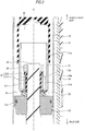
- FIG. 2 is a sectional view showing a member which is disposed on a vehicle body side leading end portion of the piston rod 20. More specifically, FIG. 2 is a sectional view of the hydraulic shock absorber 1 taken along a plane including a central axis C of the piston rod 20. As shown in FIG. 2 , the first piston 21, a valve 22, and a second piston 23 are disposed on the vehicle body side leading end portion of the piston rod 20 sequentially from the vehicle body side.
- the second piston 23 is a piston sliding against the cylinder 10.
- an internal space of the cylinder 10 is sectioned into a first oil chamber S1 which is positioned on the vehicle body side, and a second oil chamber S2 which is positioned on the axle side.
- the second piston 23 makes contact with the cylinder 10 through an O-ring 23a provided in an outer circumferential surface of the second piston 23.
- the first piston 21 is a piston which is disposed on a vehicle body side end portion of the piston rod 20 and which is shaped like a cylinder opened on the vehicle body side.
- the first piston 21 is inserted into the oil lock portion 11 in a compressed state of the hydraulic shock absorber 1. Consequently, a small oil chamber S0 is formed between the oil lock portion 11 and the first piston 21 to thereby generate an oil lock effect.
- An outer diameter of the first piston 21 is smaller than an inner diameter of the oil lock portion 11 so that a gap flow path 11a is formed between an outer circumferential surface of the first piston 21 and an inner circumferential surface of the oil lock portion 11.
- the first piston 21 has a flow path (piston internal flow path) 21a on the axle side so that the inside and the outside of the first piston 21 can communicate with each other through the flow path 21a.
- the valve 22 in which a plurality of plate valves are laminated is disposed on the axle side of the first piston 21.
- the valve 22 is a damping valve which bends against a flow of working oil to thereby generate damping force and which has a shape and a size large enough to close an axle side opening portion of the flow path 21a.
- the first piston 21 is displaceable in an axial direction of the piston rod 20 with respect to the piston rod 20.
- the piston rod 20 moves toward the vehicle body side in the compression side stroke, the first piston 21 relatively moves toward the axle side with respect to the piston rod 20.
- the piston rod 20 moves toward the axle side in an extension side stroke, the first piston 21 relatively moves toward the vehicle body side with respect to the piston rod 20.
- the first piston 21 has a small diameter portion 211 on the axle side.
- the small diameter portion 211 is smaller in inner diameter than any other portion of the first piston 21.
- the aforementioned flow path 21a is formed to penetrate the small diameter portion 211 axially.
- a spacer 27shaped like a tube is disposed on an outer circumferential surface of the piston rod 20.
- the spacer 27 has a small diameter portion 271 and a large diameter portion 272.
- the large diameter portion 272 having an outer diameter larger than an outer diameter of the small diameter portion 271 is positioned on the vehicle body side with respect to the small diameter portion 271.
- the small diameter portion 211 of the first piston 21 is disposed on a radially outer side of the small diameter portion 271.
- the spacer 27 An axle side end portion of the spacer 27 abuts against the valve 22.
- a vehicle body side end portion of the spacer 27 abuts against a stopper 28 provided on a vehicle body side end portion of the piston rod 20. Therefore, the spacer 27 is not displaced axially.
- the stopper 28 may be, for example, a nut engaged with a screw groove provided in the vehicle body side end portion of the piston rod 20.
- a length of the small diameter portion 271 of the spacer 27 is axially longer than a length of the small diameter portion 211 of the first piston 21. Therefore, the first piston 21 can be axially displaced between the large diameter portion 272 of the spacer 27 and the valve 22.
- valve spring 29 urging the first piston 21 toward the axle side, i.e. toward the side where the valve 22 is positioned is disposed between the small diameter portion 211 and the large diameter portion 272 in the axial direction.
- the valve spring 29 is an annular member having elasticity, such as a coil spring etc.
- the first piston 21 In a situation that oil pressure is not applied to the first piston 21, the first piston 21 is displaced toward the axle side by elastic force of the valve spring 29 to abut against the valve 22.
- the first piston 21 In addition, in the compression side stroke, the first piston 21 abuts against the valve 22 more intensely due to resistance of the working oil received because the first piston 21 moves toward the vehicle body side, in addition to the elastic force of the valve spring 29.
- oil pressure in the small oil chamber S0 decreases temporarily because the first piston 21 moves toward the axle side. Due to a difference in oil pressure between the small oil diameter S0 and the first oil diameter S1 generated on this occasion, the first piston 21 is displaced toward the vehicle body side against the elastic force of the valve spring 29.
- FIG. 3A is a sectional view showing a positional relation between the first piston 21 and the valve 22 in the compression side stroke.
- FIG. 3B is a sectional view showing a positional relation between the first piston 21 and the valve 22 in the extension side stroke.
- the axle side end surface of the first piston 21 and the valve 22 are separated from each other, as shown in FIG. 3B . Therefore, in the extension side stroke, the axle side opening portion of the flow path 21a is opened so that the working oil can flow into the small oil chamber S0 through the flow path 21a. Therefore, it is possible to prevent the small oil chamber S0 from becoming negative pressure in accordance with the relative movement of the first piston 21 toward the axle side.
- an external diameter of the small diameter portion 271 of the spacer 27 is smaller slightly (e.g. by 0.2 mm) than an internal diameter of the small diameter portion 211 of the first piston 21. Therefore, the first piston 21 can be also displaced in a radial direction of the piston rod 20.
- a vehicle body side end portion of the first piston 21 is tapered. Therefore, it is possible to realize a configuration in which even when accuracy of positioning between the first piston 21 and the oil lock portion 11 is not increased, the vehicle body side end portion of the first piston 21 can be guided by an axle side end portion of the oil lock portion 11 so that the first piston 21 can be inserted into the oil lock portion 11.
- the first piston 21 does not have to be always shaped like a cylinder, but may be shaped like a tube having another section than a circular section, such as a quadrangular prism section.
- the shape of the section of the oil lock portion 11 is also a shape fitted to the shape of the section of the first piston 21.
- each of the first piston 21 and the oil lock portion 11 has a circular shape in section.
- a mounting member 24 for mounting the hydraulic shock absorber 1 on the axle, and a spring bearing 25 against which the suspension spring 60 abuts are provided on the axle side of the piston rod 20.
- a bump rubber 26 is disposed on a vehicle body side of the mounting member 24.
- the bump rubber 26 absorbs shock when a rod guide 52 and the mounting member 24 are in contact with each other in the compression side stroke of the hydraulic shock absorber 1.
- the damping force generating portion 30 communicates with the first oil chamber S1 and the second oil chamber S2.
- the damping force generating portion 30 generates damping force in accordance with the flow of the working oil generated due to the movement of the piston rod 20.
- a specific configuration of the damping force generating portion 30 will not be shown because it is irrelevant to the present invention.
- the sub tank 40 compensates for working oil corresponding to a volume change amount inside the cylinder 10 due to displacement of the piston rod 20 with respect to the cylinder 10.
- the sub tank 40 communicates with the first oil chamber S1 and the second oil chamber S2 through the damping force generating portion 30.
- the outer cylinder 50 is a tubular member provided on an outer side of the cylinder 10.
- the outer cylinder 50 is disposed coaxially with the cylinder 10.
- An annular flow path 50a is formed between an inner circumferential surface of the outer tube 50 and an outer circumferential surface of the cylinder 10 so that the damping force generating portion 30 and the second oil chamber S2 can be made to communicate with each other through the annular flow path 50a.
- a vehicle body side spring bearing 51 against which the suspension spring 60 abuts is provided on an outer circumference of the outer tube 50.
- a rod guide 52 which the piston rod 20 penetrates is disposed in the vicinity of an axle side end portion of the outer tube 50.
- the rod guide 52 is a member which is generally shaped like a thick cylinder.
- the rod guide 52 makes contact with the inner circumferential surface of the outer tube 50 through an O-ring 52a.
- the rod guide 52 supports the piston rod 20 so that the piston rod 20 can axially move in an inner hole of the rod guide 52 through an oil seal 52b, a bush 52c, and a dust seal 52d.
- a rebound rubber 52e is disposed on a vehicle body side of the rod guide 52.
- the rebound rubber 52e absorbs shock caused by contact of the second piston 23 with a vehicle body side surface of the rod guide 52 when the hydraulic shock absorber 1 is most extended.
- the suspension spring 60 is compressed to absorb vibration caused by unevenness of a road surface.
- a vehicle body side end portion of the suspension spring 60 abuts against the vehicle body side spring bearing 51 and an axle side end portion of the suspension spring 60 abuts against the axle side spring bearing 25. In this manner, the positions of the opposite ends of the suspension spring 60 are regulated.
- FIG. 1A and FIG. 1B The flow of the working oil in the hydraulic shock absorber 1 will be described with reference to FIG. 1A and FIG. 1B .
- the flow of the working oil in the compression side stroke is designated by a solid line and the flow of the working oil in the extension side stroke is designed by a broken line.
- the working oil flows from the first oil chamber S1 into the damping force generating portion 30 through the hole portions 13 in accordance with movement of the piston rod 20 toward the vehicle body side, as shown in FIG. 1A .
- some working oil corresponding to an entry volume of the piston rod 20 flows into the sub tank 40, and the remaining working oil flows into the second oil chamber S2 through the annular flow path 50a and the hole portions 14.
- the damping force can be generated in accordance with the position of the first piston 21, i.e. a depth of the stroke of the hydraulic shock absorber 1.
- the working oil in the second oil chamber S2 flows into the damping force generating portion 30 through the hole portions 14 on the axle side of the cylinder 10 and the annular flow path 50a in accordance with the movement of the second piston 23 toward the axle side.
- the working oil which has generated the damping force in the damping force generating portion 30 flows into the first oil chamber S1.
- working oil corresponding to a retraction volume of the piston rod 20 flows from the sub tank 40 into the first oil chamber S1.
- the hydraulic shock absorber 1 is provided with the cylinder 10, the piston rod 20, and the oil lock portion 11.
- the piston rod 20 is inserted into the cylinder 10.
- the first piston 21, the valve 22, and the second piston 23 sliding against the cylinder 10 are disposed on the piston rod 20 sequentially from the vehicle body side.
- the oil lock portion 11 is disposed on the vehicle body side inside the cylinder 10.
- the gap flow path 11a is formed between the oil lock portion 11 and the outer circumferential surface of the first piston 21.
- the first piston 21 has the flow path 21a through which the vehicle body side and the axle side communicate with each other. At the same time, the first piston 21 is displaceable in the axial direction of the piston rod 20.
- the first piston 21 when the piston rod 20 has arrived at the vehicle body side of the cylinder 10, the first piston 21 is inserted into the oil lock portion 11 so that the axle side end surface of the first piston 21 abuts against the valve 22.
- the oil pressure in the small oil chamber S0 increases so that a portion of the working oil in the small oil chamber S0 passes through the flow path 21a to bend the valve 22 to thereby flow out to the first oil chamber S1. Due to the valve 22 bent on this occasion, damping force occurs.
- the flow of the working oil passing through the flow path 21a is partially restricted by the valve 22. Thus, pressure of the working oil in the small oil chamber S0 increases.
- the hydraulic shock absorber 1 can efficiently generate damping force dependent on the position of the first piston 21.
- the first piston 21 is displaceable in the radial direction of the piston rod 20. Accordingly, it is possible to realize a configuration in which the first piston 21 can be inserted into the oil lock portion 11 even when the accuracy of the positioning between the first piston 21 and the oil lock portion 11 is not increased.
- the first piston 21 has a tubular shape opened on the vehicle body side, and has the flow path 21a on the axle side.
- the first piston 21 is shaped like a tube. Accordingly, it is possible to reduce the weight of the first piston 21 while securing the length of the gap flow path 11a.
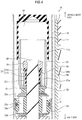
- FIG. 4 is a sectional view showing a configuration of an important part of a hydraulic shock absorber 1A according to the present embodiment.
- the hydraulic shock absorber 1A is different from the hydraulic shock absorber 1 in that the hydraulic shock absorber 1A is (i) provided with a valve 32 in place of the valve 22, (ii) provided with a second piston 33 in place of the second piston 23, and (iii) further provided with damping valves 23c and 23d (damping force generating valves).
- the valve 32 is not a valve for generating damping but a valve for restricting a flow of working oil passing through a flow path 21a.
- a compression side stroke of the hydraulic shock absorber 1A an axle side opening portion of the flow path 21a is closed by the valve 32. Accordingly, the working oil is retrained from flowing through the flow path 21a. Therefore, in comparison with the hydraulic shock absorber 1, an amount of the working oil flowing through a gap flow path 11a increases, and damping force occurring in the gap flow path 11a increases.
- the second piston 33 has a flow path (second piston internal flow path) 23b through which a vehicle body side and an axle side communicate with each other.
- the damping valves 23c and 23d are disposed on a vehicle body side opening portion and an axle side opening portion of the flow path 23b respectively.
- the working oil passes through the flow path 23b in accordance with movement of the second piston 31 through a first oil chamber S1 in a compression side stroke and an extension side stroke. Due to the damping valve 23c or 23d bending on this occasion, damping force occurs. Therefore, it is possible to also generate damping force in the second piston 33 in the hydraulic shock absorber 1A.
- FIG. 5A is a conceptual view showing a configuration of an important part of a hydraulic shock absorber 2 according to the present embodiment, i.e. a partial sectional view showing a state in which a first piston 21D is positioned on an axle side with respect to an opening portion 10b of a cylinder 10A in a compression side stroke.
- FIG. 5B is a conceptual view showing the configuration of the important part of the hydraulic shock absorber 2 according to the present embodiment, i.e. a partial sectional view showing a state in which the first piston 21D is positioned on a vehicle body side with respect to the opening portion 10b in the compression side stroke.
- FIG. 5C is a conceptual view showing the configuration of the important part of the hydraulic shock absorber 2 according to the present embodiment, i.e.
- FIG. 5A to FIG. 5C a positional relation between a member such as the first piston 21D disposed on a vehicle body side end portion of a piston rod 20 and the opening portion 10b is schematically shown, but description about other members is omitted.
- a flow of working oil in the compression side stroke is designated by a solid line and the flow of the working oil in the extension side stroke is designated by a broken line.
- the hydraulic shock absorber 2 is different from the hydraulic shock absorber 1 in that the hydraulic shock absorber 2 is provided with the cylinder 10A in place of the cylinder 10, and provided with the first piston 21D in place of the first piston 21.
- the hydraulic shock absorber 2 is different from the hydraulic shock absorber 1 in that the hydraulic shock absorber 2 is not provided with any oil lock portion 11 but the opening portion 10b for letting out the working oil is formed in a vehicle body side wall portion.
- the first piston 21D is different from the first piston 21 in that the first piston 21D has a large diameter portion 21b forming a gap flow path 21c between the large diameter portion 21b and an inner surface of the cylinder 10A.
- a space provided on the vehicle body side with respect to the large diameter portion 21b inside the cylinder 10A is a small oil chamber S0.
- a space between the large diameter portion 21b and a second piston 23 is a first oil chamber S1.
- the whole of the first piston 21D serves as the large diameter portion 21b.
- the large diameter portion 21b may be formed as a portion of the first piston 21D.
- a thickness of the large diameter portion 21b in an axial direction of the piston rod 20 is larger than an aperture of the opening portion 10b. That is, the large diameter portion 21b has a thickness large enough to cover the opening portion 10b.
- a spring bearing 291 is provided in the vicinity of a vehicle body side end portion of the piston rod 20 in the present embodiment.
- the position of a vehicle body side end portion of a valve spring 29 is regulated by the spring bearing 291.
- first piston 21D has a flow path (piston internal flow path) 21a in a similar manner to or the same manner as the first piston 21. At the same time, the first piston 21D is displaceable in the axial direction of the piston rod 20.
- a tubular retention member 221 having a step in the axial direction is disposed on an outer circumferential surface of the piston rod 20 between the first piston 21D and the second piston 23.
- a valve 22 in the present embodiment is retained in the vicinity of the first piston 21D by the retention member 221.
- the working oil in the small oil chamber S0 flows into a damping force generating portion 30 from hole portions 13 to thereby generate damping force. Then, some working oil corresponding to an entry volume of the piston rod 20 flows into a sub tank 40 and the remaining working oil flows into a second oil chamber S2.
- the working oil in the second oil chamber S2 flows into the damping force generating portion 30 to generate damping force, and the working oil then flows into the small oil chamber S0.
- a portion of the working oil from the second oil chamber S2 flows into the first oil chamber S1 through the opening portion 10b.
- some working oil corresponding to a retraction volume of the piston rod 20 flows from the sub tank 40 into the small oil chamber S0.
- the first piston 21 moves toward the axle side in the extension side stroke so that oil pressure in the small oil chamber S0 temporarily decreases. Due to a difference in oil pressure between the small oil chamber S0 and the first oil chamber S1 generated on this occasion, the first piston 21 is displaced toward the vehicle body side against elastic force of the valve spring 29. On this occasion, an axle side opening portion of the flow path 21a is opened. Accordingly, the working oil in the first oil chamber S1 flows into the small oil chamber S0 through the flow path 21a.
- a flow path 23b and damping valves 23c and 23d of the second piston 23 are not shown in FIG. 5A to FIG. 5C .
- the second piston 23 may have the flow path 23b and the damping valves 23c and 23d in a similar manner to or the same manner as the hydraulic shock absorber 1A in the embodiment 2.
- the hydraulic shock absorber 2 in the present embodiment is provided with the cylinder 10A and the piston rod 20.
- the opening portion 10b for letting out the working oil is formed in the vehicle body side wall portion.
- the piston rod 20 is inserted into the cylinder 10A.
- the first piston 21D, the valve 22 and the second piston 23 are disposed on the piston rod 20 sequentially from the vehicle body side.
- the first piston 21D has the large diameter portion 21b which is larger in diameter than any other portion of the first piston 21D, and which has the gap flow path 21c formed between the large diameter portion 21b and the inner surface of the cylinder 10A. Further, the first piston 21D has the flow path 21a through which the vehicle body side and the axle side communicate with each other.
- the first piston 21D is displaceable in the axial direction of the piston rod 20.
- the first piston 21D moves toward the axle side so that an axle side of the first piston 21D abuts against the valve 22, and due to the flow of the working oil passing through the flow path 21a, the valve 22 bends to generate damping force.
- the piston rod 20 When the piston rod 20 then moves toward the axle side, the first piston 21D moves toward the vehicle body side, and the opening portion of the flow path 21a is opened. Therefore, the working oil flows into the small oil chamber S0 through the flow path 21a.
- the small oil chamber S0 is formed by the cylinder 10 and the first piston 21D. Therefore, it is possible to prevent the small oil chamber S0 from becoming negative pressure so that it is possible to make the hydraulic shock absorber 2 work stably.
- the present invention is not limited to the aforementioned respective embodiments but may be changed variously within the scope described in CLAIMS. Any embodiment obtained by suitably combining technical means disclosed respectively in different embodiments is also included in the technical scope of the present invention.
Abstract
Description
- The present invention relates to a hydraulic shock absorber which absorbs shock from a road surface.
- A hydraulic shock absorber provided with a piston moving in an axial direction of a piston rod in response to extension/compression of an elastic body has been disclosed in
PTL 1. The piston is pressed so that one end surface of the piston can be contacted with or separated from a damping valve by the elastic body. - A shock absorber in which a first piston mounted on a piston rod is inserted into a cup-like component inside a cylinder has been disclosed in
PTL 2. In the shock absorber, the first piston is inserted into an internal space of the cup-like component so that different damping force from that in a case where the first piston is positioned outside the internal space occurs. -
- PTL 1: Japanese Unexamined Patent Application Publication "
JP-A-2013-96474 (Laid Open on May 20, 2013 - PTL 2: Japanese Unexamined Patent Application Publication "
JP-A-2000-170821 (Laid Open on June 23, 2000 - According to the invention of
PTL 1, the magnitude of occurring damping force cannot be changed in accordance with the position of the piston. - According to the invention of
PTL 2, when the first piston enters the cup-like component, working oil flows through a flow path formed in the first piston so that the damping force occurs. - An object of the present invention is to provide a hydraulic shock absorber which can use a different mechanism from the background art to generate damping force dependent on the position of a piston.
- In order to solve the foregoing problem, according to an aspect of the present invention, there is provided a hydraulic shock absorber including: a cylinder; a piston rod that is inserted into the cylinder, and on which a first piston, a valve, and a second piston configured to slide against the cylinder are disposed sequentially from one end side; and an oil lock portion that is disposed on the one end side inside the cylinder, and that forms a gap flow path between the oil lock portion and an outer circumferential surface of the first piston when the first piston is inserted into the oil lock portion; wherein: the first piston has a piston internal flow path through which the one end side and the other end side that is an opposite side to the one end side communicate with each other, and the first piston is displaceable in an axial direction of the piston rod; and when the piston rod moves toward the one end side, the first piston relatively moves toward the other end side and the other end side of the first piston abuts against the valve, so that due to a flow of working oil passing through the piston internal flow path, the valve bends to generate damping force.
- In addition, according to another aspect of the present invention, there is provided a hydraulic shock absorber including: a cylinder in which an opening portion for letting out working oil is formed in a one end side wall portion; and a piston rod that is inserted into the cylinder and on which a first piston, a valve and a second piston are disposed sequentially from the one end side; wherein: the first piston has a large diameter portion that is larger in diameter than any other portion of the first piston and that forms a gap flow path between the large diameter portion and an inner surface of the cylinder; the first piston further has a piston internal flow path through which the one end side and the other end side that is an opposite side to the one end side communicate with each other, and the first piston is displaceable in an axial direction of the piston rod; and when the piston rod moves toward the one end side, the first piston moves toward the other end side and the other end side of the first piston abuts against the valve, so that due to a flow of working oil passing through the piston internal flow path, the valve bends to generate damping force.
- In addition, according to a further aspect of the present invention, there is provided a hydraulic shock absorber including: a cylinder; a piston rod that is inserted into the cylinder, and on which a first piston, a valve, and a second piston configured to slide against the cylinder are disposed sequentially from one end side; and an oil lock portion that is disposed on the one end side inside the cylinder, and that forms a gap flow path between the oil lock portion and an outer circumferential surface of the first piston when the first piston is inserted into the oil lock portion; wherein: the first piston has a piston internal flow path through which the one end side and the other end side communicate with each other, and is displaceable in an axial direction of the piston rod; and when the piston rod moves toward the one end side, the first piston relatively moves toward the other end side with respect to the piston rod and the other end side of the first piston abuts against the valve, so that due to a flow of working oil passing through the piston internal flow path, the valve bends to generate damping force.
- According to an aspect of the present invention, it is possible to provide a hydraulic shock absorber which can generate damping force dependent on the position of a piston.
-
- [
FIG. 1A ] A view showing an overall configuration of an extended state of a hydraulic shock absorber according toEmbodiment 1 of the present invention. - [
FIG. 1B ] A view showing an overall configuration of a state halfway through a compression stroke of the hydraulic shock absorber according toEmbodiment 1 of the present invention. - [
FIG. 2 ] A sectional view showing a member disposed on a vehicle body side leading end portion of a piston rod. - [
FIG. 3A ] A sectional view showing a positional relation between a first piston and a valve in the compression side stroke. - [
FIG. 3B ] A sectional view showing a positional relation between the first piston and the valve in an extension side stroke. - [
FIG. 4 ] A sectional view showing a configuration of an important part of a hydraulic shock absorber according toEmbodiment 2 of the present invention. - [
FIG. 5A ] A conceptual view showing a configuration of an important part of a hydraulic shock absorber according to Embodiment 3 of the present invention, i.e. a partial sectional view showing a state in which a first piston is positioned on an axle side with respect to an opening portion of a cylinder. - [
FIG. 5B ] A conceptual view showing the configuration of the important part of the hydraulic shock absorber according toEmbodiment 2 of the present invention, i.e. a partial sectional view showing a state in which the first piston is positioned on a vehicle body side with respect to the opening portion in a compression side stroke. - [
FIG. 5C ] A conceptual view showing the configuration of the important part of the hydraulic shock absorber according toEmbodiment 2 of the present invention, i.e. a partial sectional view showing a state in which the first piston is positioned on the vehicle body side with respect to the opening portion in an extension side stroke. - An embodiment of the present invention will be described below in detail.
-
FIG. 1A is a view showing an overall configuration of an extended state of a hydraulic shock absorber 1 according to the present embodiment.FIG. 1B is a view showing an overall configuration of a state halfway through a compression stroke of the hydraulic shock absorber 1 according to the present embodiment. Thehydraulic shock absorber 1 is a shock absorber used for rear cushion etc. of a motorcycle. The vehicle in which thehydraulic shock absorber 1 is mounted is not limited particularly but may be a two-wheeled vehicle or a four-wheeled vehicle. As shown inFIG. 1A andFIG. 1B , thehydraulic shock absorber 1 is provided with acylinder 10, apiston rod 20, a dampingforce generating portion 30, asub tank 40, anouter tube 50, and asuspension spring 60. - The
cylinder 10 is a tubular member whose vehicle body side (one end side) end portion is fixed to amounting member 12, and which is internally filled with working oil. Themounting member 12 is a member for mounting the hydraulic shock absorber 1 on the vehicle body. A plurality ofhole portions 13 are formed in a vehicle body side portion of thecylinder 10 so that the inside of thecylinder 10 and the dampingforce generating portion 30 can communicate with each other through thehole portions 13. In addition, a plurality ofhole portions 14 are formed in an axle side portion of thecylinder 10 so that the inside of thecylinder 10 and the dampingforce generating portion 30 communicate with each other through thehole portions 14. - An
oil lock portion 11 shaped like a tube whose axle side (the other end side) is opened is disposed on the vehicle body side inside thecylinder 10. Afirst piston 21 which will be described later is inserted into theoil lock portion 11 so that the working oil present between theoil lock portion 11 and thefirst piston 21 is compressed. Thus, it is possible to obtain an effect that bottoming of thehydraulic shock absorber 1 can be prevented. The aforementioned effect will be hereinafter called "oil lock effect". - The
piston rod 20 is a rod-like member which is inserted into thecylinder 10 from the axle side.FIG. 2 is a sectional view showing a member which is disposed on a vehicle body side leading end portion of thepiston rod 20. More specifically,FIG. 2 is a sectional view of the hydraulic shock absorber 1 taken along a plane including a central axis C of thepiston rod 20. As shown inFIG. 2 , thefirst piston 21, avalve 22, and asecond piston 23 are disposed on the vehicle body side leading end portion of thepiston rod 20 sequentially from the vehicle body side. - The
second piston 23 is a piston sliding against thecylinder 10. By thesecond piston 23, an internal space of thecylinder 10 is sectioned into a first oil chamber S1 which is positioned on the vehicle body side, and a second oil chamber S2 which is positioned on the axle side. Thesecond piston 23 makes contact with thecylinder 10 through an O-ring 23a provided in an outer circumferential surface of thesecond piston 23. - The
first piston 21 is a piston which is disposed on a vehicle body side end portion of thepiston rod 20 and which is shaped like a cylinder opened on the vehicle body side.
Thefirst piston 21 is inserted into theoil lock portion 11 in a compressed state of thehydraulic shock absorber 1. Consequently, a small oil chamber S0 is formed between theoil lock portion 11 and thefirst piston 21 to thereby generate an oil lock effect. - An outer diameter of the
first piston 21 is smaller than an inner diameter of theoil lock portion 11 so that agap flow path 11a is formed between an outer circumferential surface of thefirst piston 21 and an inner circumferential surface of theoil lock portion 11. When working oil of the small oil chamber S0 is compressed in a compression side stroke, the working oil in the small oil chamber S0 passes through thegap flow path 11a and flows out of the small oil chamber S0. On this occasion, damping force occurs in thegap flow path 11a. - The
first piston 21 has a flow path (piston internal flow path) 21a on the axle side so that the inside and the outside of thefirst piston 21 can communicate with each other through theflow path 21a. Thevalve 22 in which a plurality of plate valves are laminated is disposed on the axle side of thefirst piston 21. Thevalve 22 is a damping valve which bends against a flow of working oil to thereby generate damping force and which has a shape and a size large enough to close an axle side opening portion of theflow path 21a. - The
first piston 21 is displaceable in an axial direction of thepiston rod 20 with respect to thepiston rod 20. When thepiston rod 20 moves toward the vehicle body side in the compression side stroke, thefirst piston 21 relatively moves toward the axle side with respect to thepiston rod 20. On the contrary, when thepiston rod 20 moves toward the axle side in an extension side stroke, thefirst piston 21 relatively moves toward the vehicle body side with respect to thepiston rod 20. - Specifically, the
first piston 21 has asmall diameter portion 211 on the axle side. Thesmall diameter portion 211 is smaller in inner diameter than any other portion of thefirst piston 21. Theaforementioned flow path 21a is formed to penetrate thesmall diameter portion 211 axially. A spacer 27shaped like a tube is disposed on an outer circumferential surface of thepiston rod 20. Thespacer 27 has asmall diameter portion 271 and alarge diameter portion 272. Thelarge diameter portion 272 having an outer diameter larger than an outer diameter of thesmall diameter portion 271 is positioned on the vehicle body side with respect to thesmall diameter portion 271. Thesmall diameter portion 211 of thefirst piston 21 is disposed on a radially outer side of thesmall diameter portion 271. - An axle side end portion of the
spacer 27 abuts against thevalve 22. A vehicle body side end portion of thespacer 27 abuts against astopper 28 provided on a vehicle body side end portion of thepiston rod 20. Therefore, thespacer 27 is not displaced axially. Thestopper 28 may be, for example, a nut engaged with a screw groove provided in the vehicle body side end portion of thepiston rod 20. - A length of the
small diameter portion 271 of thespacer 27 is axially longer than a length of thesmall diameter portion 211 of thefirst piston 21. Therefore, thefirst piston 21 can be axially displaced between thelarge diameter portion 272 of thespacer 27 and thevalve 22. - In addition, a
valve spring 29 urging thefirst piston 21 toward the axle side, i.e. toward the side where thevalve 22 is positioned is disposed between thesmall diameter portion 211 and thelarge diameter portion 272 in the axial direction. Thevalve spring 29 is an annular member having elasticity, such as a coil spring etc. - In a situation that oil pressure is not applied to the
first piston 21, thefirst piston 21 is displaced toward the axle side by elastic force of thevalve spring 29 to abut against thevalve 22. In addition, in the compression side stroke, thefirst piston 21 abuts against thevalve 22 more intensely due to resistance of the working oil received because thefirst piston 21 moves toward the vehicle body side, in addition to the elastic force of thevalve spring 29. On the other hand, in the extension side stroke, oil pressure in the small oil chamber S0 decreases temporarily because thefirst piston 21 moves toward the axle side. Due to a difference in oil pressure between the small oil diameter S0 and the first oil diameter S1 generated on this occasion, thefirst piston 21 is displaced toward the vehicle body side against the elastic force of thevalve spring 29. -
FIG. 3A is a sectional view showing a positional relation between thefirst piston 21 and thevalve 22 in the compression side stroke.FIG. 3B is a sectional view showing a positional relation between thefirst piston 21 and thevalve 22 in the extension side stroke. - In the compression side stroke, an axle side end surface of the
first piston 21 and thevalve 22 abut against each other, as shown inFIG. 3A . When thefirst piston 21 enters theoil lock portion 11 in this state, the oil pressure in the small oil chamber S0 increases so that a portion of the working oil in the small oil chamber S0 passes through theflow path 21a to bend thevalve 22 so as to flow out to the first oil chamber S1. Due to thevalve 22 bending on this occasion, damping force occurs. At the same time, another portion of the working oil in the small oil chamber S0 flows through thegap flow path 11a. On this occasion, damping force also occurs in thegap flow path 11a. - On the other hand, in the extension side stroke, the axle side end surface of the
first piston 21 and thevalve 22 are separated from each other, as shown inFIG. 3B . Therefore, in the extension side stroke, the axle side opening portion of theflow path 21a is opened so that the working oil can flow into the small oil chamber S0 through theflow path 21a.
Therefore, it is possible to prevent the small oil chamber S0 from becoming negative pressure in accordance with the relative movement of thefirst piston 21 toward the axle side. - In addition, an external diameter of the
small diameter portion 271 of thespacer 27 is smaller slightly (e.g. by 0.2 mm) than an internal diameter of thesmall diameter portion 211 of thefirst piston 21. Therefore, thefirst piston 21 can be also displaced in a radial direction of thepiston rod 20. In addition, a vehicle body side end portion of thefirst piston 21 is tapered. Therefore, it is possible to realize a configuration in which even when accuracy of positioning between thefirst piston 21 and theoil lock portion 11 is not increased, the vehicle body side end portion of thefirst piston 21 can be guided by an axle side end portion of theoil lock portion 11 so that thefirst piston 21 can be inserted into theoil lock portion 11. - Incidentally, the
first piston 21 does not have to be always shaped like a cylinder, but may be shaped like a tube having another section than a circular section, such as a quadrangular prism section. In this case, the shape of the section of theoil lock portion 11 is also a shape fitted to the shape of the section of thefirst piston 21. However, when the section of thefirst piston 21 is circular, it is unnecessary to perform angular alignment between thefirst piston 21 and theoil lock portion 11. Therefore, it is preferable that each of thefirst piston 21 and theoil lock portion 11 has a circular shape in section. - As shown in
FIG. 1A andFIG. 1B , a mountingmember 24 for mounting thehydraulic shock absorber 1 on the axle, and aspring bearing 25 against which thesuspension spring 60 abuts are provided on the axle side of thepiston rod 20. - A
bump rubber 26 is disposed on a vehicle body side of the mountingmember 24. Thebump rubber 26 absorbs shock when a rod guide 52 and the mountingmember 24 are in contact with each other in the compression side stroke of thehydraulic shock absorber 1. - The damping
force generating portion 30 communicates with the first oil chamber S1 and the second oil chamber S2. The dampingforce generating portion 30 generates damping force in accordance with the flow of the working oil generated due to the movement of thepiston rod 20. Incidentally, a specific configuration of the dampingforce generating portion 30 will not be shown because it is irrelevant to the present invention. - The
sub tank 40 compensates for working oil corresponding to a volume change amount inside thecylinder 10 due to displacement of thepiston rod 20 with respect to thecylinder 10. Thesub tank 40 communicates with the first oil chamber S1 and the second oil chamber S2 through the dampingforce generating portion 30. - The
outer cylinder 50 is a tubular member provided on an outer side of thecylinder 10. Theouter cylinder 50 is disposed coaxially with thecylinder 10. Anannular flow path 50a is formed between an inner circumferential surface of theouter tube 50 and an outer circumferential surface of thecylinder 10 so that the dampingforce generating portion 30 and the second oil chamber S2 can be made to communicate with each other through theannular flow path 50a. A vehicle body side spring bearing 51 against which thesuspension spring 60 abuts is provided on an outer circumference of theouter tube 50. - In addition, a rod guide 52 which the
piston rod 20 penetrates is disposed in the vicinity of an axle side end portion of theouter tube 50. The rod guide 52 is a member which is generally shaped like a thick cylinder. The rod guide 52 makes contact with the inner circumferential surface of theouter tube 50 through an O-ring 52a. In addition, the rod guide 52 supports thepiston rod 20 so that thepiston rod 20 can axially move in an inner hole of the rod guide 52 through anoil seal 52b, a bush 52c, and a dust seal 52d. - In addition, a
rebound rubber 52e is disposed on a vehicle body side of the rod guide 52. Therebound rubber 52e absorbs shock caused by contact of thesecond piston 23 with a vehicle body side surface of the rod guide 52 when thehydraulic shock absorber 1 is most extended. - The
suspension spring 60 is compressed to absorb vibration caused by unevenness of a road surface. A vehicle body side end portion of thesuspension spring 60 abuts against the vehicle bodyside spring bearing 51 and an axle side end portion of thesuspension spring 60 abuts against the axleside spring bearing 25. In this manner, the positions of the opposite ends of thesuspension spring 60 are regulated. - The flow of the working oil in the
hydraulic shock absorber 1 will be described with reference toFIG. 1A andFIG. 1B . InFIG. 1A andFIG. 1B , the flow of the working oil in the compression side stroke is designated by a solid line and the flow of the working oil in the extension side stroke is designed by a broken line. - In the compression side stroke, the working oil flows from the first oil chamber S1 into the damping
force generating portion 30 through thehole portions 13 in accordance with movement of thepiston rod 20 toward the vehicle body side, as shown inFIG. 1A . Of the working oil flowing into the dampingforce generating portion 30, some working oil corresponding to an entry volume of thepiston rod 20 flows into thesub tank 40, and the remaining working oil flows into the second oil chamber S2 through theannular flow path 50a and thehole portions 14. - Further, in a state the
first piston 21 is inserted into the oil lock portion 11 (a trailing end of a stroke) in the compression side stroke, the working oil in the small oil chamber S0 flows into the first oil chamber S1 through thegap flow path 11a, as shown inFIG. 3A . Damping force occurs due to the flow of the working oil. In addition, since the working oil in the small chamber S0 bends thevalve 22 from theflow path 21a to flow into the first oil chamber S1, damping force also occurs. Accordingly, the damping force can be generated in accordance with the position of thefirst piston 21, i.e. a depth of the stroke of thehydraulic shock absorber 1. - When the
first piston 21 moves toward the outside of theoil lock portion 11 in the extension side stroke, a portion of the working oil in the first oil chamber S1 flows from thegap flow path 11a and theflow path 21a into the small oil chamber S0, as shown inFIG. 3B . - In addition, the working oil in the second oil chamber S2 flows into the damping
force generating portion 30 through thehole portions 14 on the axle side of thecylinder 10 and theannular flow path 50a in accordance with the movement of thesecond piston 23 toward the axle side. The working oil which has generated the damping force in the dampingforce generating portion 30 flows into the first oil chamber S1. Further, working oil corresponding to a retraction volume of thepiston rod 20 flows from thesub tank 40 into the first oil chamber S1. - As described above, the
hydraulic shock absorber 1 according to the present embodiment is provided with thecylinder 10, thepiston rod 20, and theoil lock portion 11. Thepiston rod 20 is inserted into thecylinder 10. Thefirst piston 21, thevalve 22, and thesecond piston 23 sliding against thecylinder 10 are disposed on thepiston rod 20 sequentially from the vehicle body side. Theoil lock portion 11 is disposed on the vehicle body side inside thecylinder 10. When thefirst piston 21 is inserted into theoil lock portion 11, thegap flow path 11a is formed between theoil lock portion 11 and the outer circumferential surface of thefirst piston 21. Thefirst piston 21 has theflow path 21a through which the vehicle body side and the axle side communicate with each other. At the same time, thefirst piston 21 is displaceable in the axial direction of thepiston rod 20. When thepiston rod 20 moves toward the vehicle body side, thefirst piston 21 relatively moves toward the axle side with respect to thepiston rod 20. As a result, the axle side of thefirst piston 21 abuts against thevalve 22. Due to thevalve 22 bent by the flow of the working oil passing through theflow path 21a, the damping force is generated. - According to the aforementioned configuration, when the
piston rod 20 has arrived at the vehicle body side of thecylinder 10, thefirst piston 21 is inserted into theoil lock portion 11 so that the axle side end surface of thefirst piston 21 abuts against thevalve 22. When thefirst piston 21 enters theoil lock portion 11 in this state, the oil pressure in the small oil chamber S0 increases so that a portion of the working oil in the small oil chamber S0 passes through theflow path 21a to bend thevalve 22 to thereby flow out to the first oil chamber S1. Due to thevalve 22 bent on this occasion, damping force occurs. In addition, the flow of the working oil passing through theflow path 21a is partially restricted by thevalve 22. Thus, pressure of the working oil in the small oil chamber S0 increases. Due to the working oil flowing through thegap flow path 11a formed between the outer circumferential surface of thefirst piston 21 and an inner surface of theoil lock portion 11, damping force also occurs. Accordingly, thehydraulic shock absorber 1 can efficiently generate damping force dependent on the position of thefirst piston 21. - When the
piston rod 20 moves toward the axle side, thefirst piston 21 moves toward the vehicle body side so that the opening portion of theflow path 21a is opened. Accordingly, the working oil flows into the small oil chamber S0 through theflow path 21a. Therefore, it is possible to prevent the small oil chamber S0 from becoming negative pressure so that it is possible to make thehydraulic shock absorber 1 work stably. - In addition, in the
hydraulic shock absorber 1, thefirst piston 21 is displaceable in the radial direction of thepiston rod 20. Accordingly, it is possible to realize a configuration in which thefirst piston 21 can be inserted into theoil lock portion 11 even when the accuracy of the positioning between thefirst piston 21 and theoil lock portion 11 is not increased. - In addition, in the
hydraulic shock absorber 1, thefirst piston 21 has a tubular shape opened on the vehicle body side, and has theflow path 21a on the axle side. Thus, thefirst piston 21 is shaped like a tube. Accordingly, it is possible to reduce the weight of thefirst piston 21 while securing the length of thegap flow path 11a. - Another embodiment of the present invention will be described below. Incidentally, for convenience of explanation, members having the same functions as the members described in the aforementioned embodiment will be referred to by the same signs correspondingly and respectively, and description thereof will be omitted.
-
FIG. 4 is a sectional view showing a configuration of an important part of ahydraulic shock absorber 1A according to the present embodiment. Thehydraulic shock absorber 1A is different from thehydraulic shock absorber 1 in that thehydraulic shock absorber 1A is (i) provided with avalve 32 in place of thevalve 22, (ii) provided with asecond piston 33 in place of thesecond piston 23, and (iii) further provided with dampingvalves - The
valve 32 is not a valve for generating damping but a valve for restricting a flow of working oil passing through aflow path 21a. In a compression side stroke of thehydraulic shock absorber 1A, an axle side opening portion of theflow path 21a is closed by thevalve 32. Accordingly, the working oil is retrained from flowing through theflow path 21a. Therefore, in comparison with thehydraulic shock absorber 1, an amount of the working oil flowing through agap flow path 11a increases, and damping force occurring in thegap flow path 11a increases. - The
second piston 33 has a flow path (second piston internal flow path) 23b through which a vehicle body side and an axle side communicate with each other. The dampingvalves valve second piston 33 in thehydraulic shock absorber 1A. - Another embodiment of the present invention will be described below. Incidentally, for convenience of explanation, members having the same functions as the members described in the aforementioned embodiments will be referred to by the same signs correspondingly and respectively, and description thereof will be omitted.
-
FIG. 5A is a conceptual view showing a configuration of an important part of ahydraulic shock absorber 2 according to the present embodiment, i.e. a partial sectional view showing a state in which afirst piston 21D is positioned on an axle side with respect to anopening portion 10b of acylinder 10A in a compression side stroke.FIG. 5B is a conceptual view showing the configuration of the important part of thehydraulic shock absorber 2 according to the present embodiment, i.e. a partial sectional view showing a state in which thefirst piston 21D is positioned on a vehicle body side with respect to theopening portion 10b in the compression side stroke.FIG. 5C is a conceptual view showing the configuration of the important part of thehydraulic shock absorber 2 according to the present embodiment, i.e. a partial sectional view showing a state in which thefirst piston 21D is positioned on the vehicle body side with respect to theopening portion 10b in an extension side stroke. InFIG. 5A to FIG. 5C , a positional relation between a member such as thefirst piston 21D disposed on a vehicle body side end portion of apiston rod 20 and theopening portion 10b is schematically shown, but description about other members is omitted. A flow of working oil in the compression side stroke is designated by a solid line and the flow of the working oil in the extension side stroke is designated by a broken line. - As shown in
FIG. 5A to FIG. 5C , thehydraulic shock absorber 2 is different from thehydraulic shock absorber 1 in that thehydraulic shock absorber 2 is provided with thecylinder 10A in place of thecylinder 10, and provided with thefirst piston 21D in place of thefirst piston 21. In addition, thehydraulic shock absorber 2 is different from thehydraulic shock absorber 1 in that thehydraulic shock absorber 2 is not provided with anyoil lock portion 11 but theopening portion 10b for letting out the working oil is formed in a vehicle body side wall portion. - The
first piston 21D is different from thefirst piston 21 in that thefirst piston 21D has alarge diameter portion 21b forming agap flow path 21c between thelarge diameter portion 21b and an inner surface of thecylinder 10A. In the present embodiment, a space provided on the vehicle body side with respect to thelarge diameter portion 21b inside thecylinder 10A is a small oil chamber S0. A space between thelarge diameter portion 21b and asecond piston 23 is a first oil chamber S1. - In the example shown in
FIG. 5A to FIG. 5C , the whole of thefirst piston 21D serves as thelarge diameter portion 21b. However, thelarge diameter portion 21b may be formed as a portion of thefirst piston 21D. A thickness of thelarge diameter portion 21b in an axial direction of thepiston rod 20 is larger than an aperture of theopening portion 10b. That is, thelarge diameter portion 21b has a thickness large enough to cover theopening portion 10b. - In addition, a
spring bearing 291 is provided in the vicinity of a vehicle body side end portion of thepiston rod 20 in the present embodiment. The position of a vehicle body side end portion of avalve spring 29 is regulated by thespring bearing 291. - In addition, the
first piston 21D has a flow path (piston internal flow path) 21a in a similar manner to or the same manner as thefirst piston 21. At the same time, thefirst piston 21D is displaceable in the axial direction of thepiston rod 20. In addition, atubular retention member 221 having a step in the axial direction is disposed on an outer circumferential surface of thepiston rod 20 between thefirst piston 21D and thesecond piston 23. Avalve 22 in the present embodiment is retained in the vicinity of thefirst piston 21D by theretention member 221. - In the compression side stroke, the working oil in the small oil chamber S0 flows into a damping
force generating portion 30 fromhole portions 13 to thereby generate damping force. Then, some working oil corresponding to an entry volume of thepiston rod 20 flows into asub tank 40 and the remaining working oil flows into a second oil chamber S2. - Further, in a state in which the
first piston 21D is positioned on the axle side with respect to theopening portion 10b, a portion of the working oil in the small oil chamber S0 flows from theopening portion 10b into the second oil chamber S2 via anannular flow path 50a, as shown inFIG. 5A . When thefirst piston 21D arrives at the vehicle body side with respect to theopening portion 10b, working oil flowing out of theopening portion 10b decreases, and working oil flowing through thegap flow path 21c increases, as shown inFIG. 5B . On this occasion, damping force occurs due to the flow of the working oil passing through thegap flow path 21c. - In the extension side stroke, the working oil in the second oil chamber S2 flows into the damping
force generating portion 30 to generate damping force, and the working oil then flows into the small oil chamber S0. In addition, a portion of the working oil from the second oil chamber S2 flows into the first oil chamber S1 through theopening portion 10b. In addition, some working oil corresponding to a retraction volume of thepiston rod 20 flows from thesub tank 40 into the small oil chamber S0. - Further, as shown in
FIG. 5C , thefirst piston 21 moves toward the axle side in the extension side stroke so that oil pressure in the small oil chamber S0 temporarily decreases. Due to a difference in oil pressure between the small oil chamber S0 and the first oil chamber S1 generated on this occasion, thefirst piston 21 is displaced toward the vehicle body side against elastic force of thevalve spring 29. On this occasion, an axle side opening portion of theflow path 21a is opened. Accordingly, the working oil in the first oil chamber S1 flows into the small oil chamber S0 through theflow path 21a. - Incidentally, a flow path 23b and damping
valves second piston 23 are not shown inFIG. 5A to FIG. 5C . However, also in the present embodiment, thesecond piston 23 may have the flow path 23b and the dampingvalves hydraulic shock absorber 1A in theembodiment 2. - As described above, the
hydraulic shock absorber 2 in the present embodiment is provided with thecylinder 10A and thepiston rod 20. In thecylinder 10A, theopening portion 10b for letting out the working oil is formed in the vehicle body side wall portion. Thepiston rod 20 is inserted into thecylinder 10A. Thefirst piston 21D, thevalve 22 and thesecond piston 23 are disposed on thepiston rod 20 sequentially from the vehicle body side. Thefirst piston 21D has thelarge diameter portion 21b which is larger in diameter than any other portion of thefirst piston 21D, and which has thegap flow path 21c formed between thelarge diameter portion 21b and the inner surface of thecylinder 10A. Further, thefirst piston 21D has theflow path 21a through which the vehicle body side and the axle side communicate with each other. At the same time, thefirst piston 21D is displaceable in the axial direction of thepiston rod 20. When thepiston rod 20 moves toward the vehicle body side, thefirst piston 21D moves toward the axle side so that an axle side of thefirst piston 21D abuts against thevalve 22, and due to the flow of the working oil passing through theflow path 21a, thevalve 22 bends to generate damping force. - According to the aforementioned configuration, when the
first piston 21D moves toward the vehicle body side with respect to theopening portion 10b of thecylinder 10A, pressure of the working oil present on the vehicle body side with respect to theopening portion 10b increases. On this occasion, the working oil flows through thegap flow path 21c between the inner surface of thecylinder 10A and an outer circumferential surface of thelarge diameter portion 21b. As a result, the damping force occurs. Moreover, on this occasion, the axle side of thefirst piston 21D abuts against thevalve 22, and thevalve 22 bends due to the flow of the working oil passing through theflow path 21a. As a result, the damping force also occurs. Accordingly, damping force dependent on the position of thefirst piston 21D can be generated efficiently. - When the
piston rod 20 then moves toward the axle side, thefirst piston 21D moves toward the vehicle body side, and the opening portion of theflow path 21a is opened. Therefore, the working oil flows into the small oil chamber S0 through theflow path 21a. The small oil chamber S0 is formed by thecylinder 10 and thefirst piston 21D. Therefore, it is possible to prevent the small oil chamber S0 from becoming negative pressure so that it is possible to make thehydraulic shock absorber 2 work stably. - The present invention is not limited to the aforementioned respective embodiments but may be changed variously within the scope described in CLAIMS. Any embodiment obtained by suitably combining technical means disclosed respectively in different embodiments is also included in the technical scope of the present invention.
-
- 1, 1A, 2
- hydraulic shock absorber
- 10, 10A
- cylinder
- 10b
- opening portion
- 11
- oil lock portion
- 11a, 21c
- gap flow path
- 20
- piston rod
- 21, 21D
- first piston
- 21a
- flow path (piston internal flow path)
- 21b
- large diameter portion
- 22, 32
- valve
- 23, 33
- second piston
- 23b
- flow path (second piston internal flow path)
Claims (6)
- A hydraulic shock absorber comprising:a cylinder;a piston rod that is inserted into the cylinder, and on which a first piston, a valve, and a second piston configured to slide against the cylinder are disposed sequentially from one end side; andan oil lock portion that is disposed on the one end side inside the cylinder, and that forms a gap flow path between the oil lock portion and an outer circumferential surface of the first piston when the first piston is inserted into the oil lock portion; wherein:the first piston has a piston internal flow path through which the one end side and the other end side communicate with each other, and is displaceable in an axial direction of the piston rod; andwhen the piston rod moves toward the one end side, the first piston relatively moves toward the other end side with respect to the piston rod and the other end side of the first piston abuts against the valve, so that due to a flow of working oil passing through the piston internal flow path, the valve bends to generate damping force.
- The hydraulic shock absorber according to Claim 1, wherein:
the first piston is displaceable in a radial direction of the piston rod. - The hydraulic shock absorber according to Claim 1 or 2, wherein:
the first piston has a tubular shape opened on the one end side, and has the piston internal flow path on the other end side. - A hydraulic shock absorber comprising:a cylinder in which an opening portion for letting out working oil is formed in a one end side wall portion; anda piston rod that is inserted into the cylinder and on which a first piston, a valve and a second piston are disposed sequentially from the one end side; wherein:the first piston has a large diameter portion that is larger in diameter than any other portion of the first piston and that forms a gap flow path between the large diameter portion and an inner surface of the cylinder;the first piston further has a piston internal flow path through which the one end side and the other end side communicate with each other, and is displaceable in an axial direction of the piston rod; andwhen the piston rod moves toward the one end side, the first piston moves toward the other end side and the other end side of the first piston abuts against the valve, so that due to a flow of working oil passing through the piston internal flow path, the valve bends to generate damping force.
- A hydraulic shock absorber comprising:a cylinder;a piston rod that is inserted into the cylinder, and on which a first piston, a valve, and a second piston configured to slide against the cylinder are disposed sequentially from one end side; andan oil lock portion that is disposed on the one end side inside the cylinder, and that forms a gap flow path between the oil lock portion and an outer circumferential surface of the first piston when the first piston is inserted into the oil lock portion; wherein:the first piston has a piston internal flow path through which the one end side and the other end side communicate with each other, and is displaceable in an axial direction of the piston rod; andwhen the piston rod moves toward the one end side, the first piston relatively moves toward the other end side with respect to the piston rod and the other end side of the first piston abuts against the valve, so that a flow of working oil passing through the piston internal flow path is restricted.
- The hydraulic shock absorber according to any one of Claims 1 through 5, wherein:the second piston has a second piston internal flow path through which the one end side and the other end side communicate with each other; anda damping force generating valve is disposed on an opening portion of the second piston internal flow path.
Applications Claiming Priority (2)
| Application Number | Priority Date | Filing Date | Title |
|---|---|---|---|
| JP2017164641A JP6291120B1 (en) | 2017-08-29 | 2017-08-29 | Hydraulic shock absorber |
| PCT/JP2017/031568 WO2019043906A1 (en) | 2017-08-29 | 2017-09-01 | Hydraulic damper |
Publications (2)
| Publication Number | Publication Date |
|---|---|
| EP3677809A1 true EP3677809A1 (en) | 2020-07-08 |
| EP3677809A4 EP3677809A4 (en) | 2021-06-02 |
Family
ID=61628720
Family Applications (1)
| Application Number | Title | Priority Date | Filing Date |
|---|---|---|---|
| EP17923283.0A Pending EP3677809A4 (en) | 2017-08-29 | 2017-09-01 | Hydraulic damper |
Country Status (5)
| Country | Link |
|---|---|
| US (1) | US11215258B2 (en) |
| EP (1) | EP3677809A4 (en) |
| JP (1) | JP6291120B1 (en) |
| CN (1) | CN110869638B (en) |
| WO (1) | WO2019043906A1 (en) |
Cited By (2)
| Publication number | Priority date | Publication date | Assignee | Title |
|---|---|---|---|---|
| EP4075015A1 (en) * | 2021-04-14 | 2022-10-19 | BeijingWest Industries Co. Ltd. | Hydraulic damper with a hydraulic compression stop assembly |
| US11835108B2 (en) | 2021-04-14 | 2023-12-05 | Beijingwest Industries Co., Ltd. | Hydraulic damper with a hydraulic compression stop assembly |
Family Cites Families (19)
| Publication number | Priority date | Publication date | Assignee | Title |
|---|---|---|---|---|
| EP0003458B1 (en) | 1978-01-26 | 1981-12-09 | COMMISSARIAT A L'ENERGIE ATOMIQUE Etablissement de Caractère Scientifique Technique et Industriel | Shock absorber for a vehicle with an elastic suspension |
| JPS6037471Y2 (en) * | 1979-12-10 | 1985-11-08 | 厚木自動車部品株式会社 | gas spring |
| US5738190A (en) * | 1996-03-20 | 1998-04-14 | Monroe Auto Equipment Company | Flexing disc-blow off assembly for use in a shock absorber |
| US6241060B1 (en) * | 1996-10-03 | 2001-06-05 | Answer Products, Inc. | Oil damped fork |
| DE19842562C1 (en) * | 1998-09-17 | 1999-11-04 | Stabilus Gmbh | Positioning strut for motor vehicle door |
| SE515321C2 (en) * | 1998-12-02 | 2001-07-16 | Oehlins Racing Ab | Shock absorber with cylinder comprising a piston rod with at least two pistons |
| DE10041199C1 (en) | 2000-08-23 | 2001-11-29 | Mannesmann Sachs Ag | Vibration damper for use in car has fixed piston and sliding piston mounted on same piston rod, sliding piston acting against springs on either side biasing it in opposite directions |
| US7320388B2 (en) * | 2003-09-15 | 2008-01-22 | Tenneco Automotive Operating Company Inc. | Stroke dependent damping |
| JP2008057590A (en) | 2006-08-29 | 2008-03-13 | Showa Corp | Front fork |
| JP2012031887A (en) * | 2010-07-28 | 2012-02-16 | Nifco Inc | Damper |
| JP5826595B2 (en) * | 2011-10-31 | 2015-12-02 | 株式会社ショーワ | Hydraulic shock absorber valve structure |
| JP5985333B2 (en) * | 2012-09-25 | 2016-09-06 | 株式会社ショーワ | Height adjustment device for motorcycles |
| US9091320B1 (en) * | 2014-01-08 | 2015-07-28 | Thyssenkrupp Bilstein Of America, Inc. | Multi-stage shock absorber |
| DE102014210704B4 (en) | 2014-06-05 | 2016-11-24 | Zf Friedrichshafen Ag | Frequency-dependent damping valve arrangement |
| JP6377972B2 (en) * | 2014-06-13 | 2018-08-22 | ヤマハモーターハイドロリックシステム株式会社 | Single cylinder hydraulic shock absorber |
| DE112016000579B4 (en) * | 2015-02-03 | 2024-03-28 | Tenneco Automotive Operating Company Inc. | SECONDARY DAMPING ARRANGEMENT FOR A SHOCK ABSORBER |
| CN107429774B (en) * | 2015-02-06 | 2019-09-27 | 天纳克汽车营运公司 | Secondary damper assembly for damper |
| WO2016146660A1 (en) * | 2015-03-16 | 2016-09-22 | Sistemi Sospensioni S.P.A. | Hydraulic compression stop member for a hydraulic shock-absorber for a vehicle suspension |
| ITUB20151830A1 (en) * | 2015-07-02 | 2017-01-02 | Sistemi Sospensioni Spa | Hydraulic compression pad for hydraulic shock absorber for vehicle suspension, with pressure limiting device. |
-
2017
- 2017-08-29 JP JP2017164641A patent/JP6291120B1/en active Active
- 2017-09-01 WO PCT/JP2017/031568 patent/WO2019043906A1/en unknown
- 2017-09-01 CN CN201780092554.0A patent/CN110869638B/en active Active
- 2017-09-01 EP EP17923283.0A patent/EP3677809A4/en active Pending
-
2019
- 2019-12-20 US US16/722,273 patent/US11215258B2/en active Active
Cited By (2)
| Publication number | Priority date | Publication date | Assignee | Title |
|---|---|---|---|---|
| EP4075015A1 (en) * | 2021-04-14 | 2022-10-19 | BeijingWest Industries Co. Ltd. | Hydraulic damper with a hydraulic compression stop assembly |
| US11835108B2 (en) | 2021-04-14 | 2023-12-05 | Beijingwest Industries Co., Ltd. | Hydraulic damper with a hydraulic compression stop assembly |
Also Published As
| Publication number | Publication date |
|---|---|
| US11215258B2 (en) | 2022-01-04 |
| JP6291120B1 (en) | 2018-03-14 |
| CN110869638A (en) | 2020-03-06 |
| WO2019043906A1 (en) | 2019-03-07 |
| US20200141466A1 (en) | 2020-05-07 |
| EP3677809A4 (en) | 2021-06-02 |
| CN110869638B (en) | 2022-09-06 |
| JP2019044786A (en) | 2019-03-22 |
Similar Documents
| Publication | Publication Date | Title |
|---|---|---|
| US10670107B2 (en) | Hydraulic damper with a hydraulic compression stop assembly | |
| US8794404B2 (en) | Hydraulic shock absorber | |
| US9796234B2 (en) | Shock absorber | |
| US11215258B2 (en) | Hydraulic shock absorber | |
| CN111108302B (en) | Front fork and method for manufacturing front fork | |
| JP2017187109A (en) | Shock absorber | |
| JP6239420B2 (en) | Hydraulic shock absorber | |
| US10112453B2 (en) | Shock absorber | |
| JP6580262B2 (en) | Shock absorber and manufacturing method thereof | |
| EP3217036B1 (en) | Suspension device | |
| JP2007146947A (en) | Hydraulic shock absorber | |
| JP6779027B2 (en) | Buffer and manufacturing method of buffer | |
| US20170268594A1 (en) | Pressure cushioning device | |
| US20190226548A1 (en) | Shock absorber | |
| US20180031070A1 (en) | Shock absorber | |
| WO2016013311A1 (en) | Pressure cushioning device and damping force generating mechanism | |
| JP2017172739A (en) | Suspension device | |
| JP2008240745A (en) | Hydraulic shock absorber | |
| WO2018092327A1 (en) | Buffer | |
| JP2020076481A (en) | Pressure buffer device and manufacturing method of the same | |
| JP6352662B2 (en) | Suspension device | |
| WO2018163523A1 (en) | Shock absorber for vehicle | |
| JP6335667B2 (en) | shock absorber | |
| JP6274925B2 (en) | Shock absorber | |
| JP2020076480A (en) | Pressure buffer device |
Legal Events
| Date | Code | Title | Description |
|---|---|---|---|
| STAA | Information on the status of an ep patent application or granted ep patent |
Free format text: STATUS: THE INTERNATIONAL PUBLICATION HAS BEEN MADE |
|
| PUAI | Public reference made under article 153(3) epc to a published international application that has entered the european phase |
Free format text: ORIGINAL CODE: 0009012 |
|
| STAA | Information on the status of an ep patent application or granted ep patent |
Free format text: STATUS: REQUEST FOR EXAMINATION WAS MADE |
|
| 17P | Request for examination filed |
Effective date: 20191220 |
|
| AK | Designated contracting states |
Kind code of ref document: A1 Designated state(s): AL AT BE BG CH CY CZ DE DK EE ES FI FR GB GR HR HU IE IS IT LI LT LU LV MC MK MT NL NO PL PT RO RS SE SI SK SM TR |
|
| AX | Request for extension of the european patent |
Extension state: BA ME |
|
| DAV | Request for validation of the european patent (deleted) | ||
| DAX | Request for extension of the european patent (deleted) | ||
| A4 | Supplementary search report drawn up and despatched |
Effective date: 20210506 |
|
| RIC1 | Information provided on ipc code assigned before grant |
Ipc: F16F 9/34 20060101AFI20210429BHEP Ipc: F16F 9/32 20060101ALI20210429BHEP Ipc: F16F 9/516 20060101ALI20210429BHEP |
|
| RAP1 | Party data changed (applicant data changed or rights of an application transferred) |
Owner name: HITACHI AUTOMOTIVE SYSTEMS, LTD. |
|
| RAP1 | Party data changed (applicant data changed or rights of an application transferred) |
Owner name: HITACHI ASTEMO, LTD. |