EP3677736B1 - Steel bar strapping machine with a replaceable gun head and operating method thereof - Google Patents
Steel bar strapping machine with a replaceable gun head and operating method thereof Download PDFInfo
- Publication number
- EP3677736B1 EP3677736B1 EP18917485.7A EP18917485A EP3677736B1 EP 3677736 B1 EP3677736 B1 EP 3677736B1 EP 18917485 A EP18917485 A EP 18917485A EP 3677736 B1 EP3677736 B1 EP 3677736B1
- Authority
- EP
- European Patent Office
- Prior art keywords
- gun head
- main control
- control unit
- motor
- bundling machine
- Prior art date
- Legal status (The legal status is an assumption and is not a legal conclusion. Google has not performed a legal analysis and makes no representation as to the accuracy of the status listed.)
- Active
Links
Images




Classifications
-
- E—FIXED CONSTRUCTIONS
- E04—BUILDING
- E04G—SCAFFOLDING; FORMS; SHUTTERING; BUILDING IMPLEMENTS OR AIDS, OR THEIR USE; HANDLING BUILDING MATERIALS ON THE SITE; REPAIRING, BREAKING-UP OR OTHER WORK ON EXISTING BUILDINGS
- E04G21/00—Preparing, conveying, or working-up building materials or building elements in situ; Other devices or measures for constructional work
- E04G21/12—Mounting of reinforcing inserts; Prestressing
-
- B—PERFORMING OPERATIONS; TRANSPORTING
- B65—CONVEYING; PACKING; STORING; HANDLING THIN OR FILAMENTARY MATERIAL
- B65B—MACHINES, APPARATUS OR DEVICES FOR, OR METHODS OF, PACKAGING ARTICLES OR MATERIALS; UNPACKING
- B65B13/00—Bundling articles
- B65B13/02—Applying and securing binding material around articles or groups of articles, e.g. using strings, wires, strips, bands or tapes
- B65B13/025—Hand-held tools
-
- B—PERFORMING OPERATIONS; TRANSPORTING
- B23—MACHINE TOOLS; METAL-WORKING NOT OTHERWISE PROVIDED FOR
- B23Q—DETAILS, COMPONENTS, OR ACCESSORIES FOR MACHINE TOOLS, e.g. ARRANGEMENTS FOR COPYING OR CONTROLLING; MACHINE TOOLS IN GENERAL CHARACTERISED BY THE CONSTRUCTION OF PARTICULAR DETAILS OR COMPONENTS; COMBINATIONS OR ASSOCIATIONS OF METAL-WORKING MACHINES, NOT DIRECTED TO A PARTICULAR RESULT
- B23Q3/00—Devices holding, supporting, or positioning work or tools, of a kind normally removable from the machine
- B23Q3/155—Arrangements for automatic insertion or removal of tools, e.g. combined with manual handling
- B23Q3/1552—Arrangements for automatic insertion or removal of tools, e.g. combined with manual handling parts of devices for automatically inserting or removing tools
- B23Q3/15546—Devices for recognizing tools in a storage device, e.g. coding devices
-
- B—PERFORMING OPERATIONS; TRANSPORTING
- B25—HAND TOOLS; PORTABLE POWER-DRIVEN TOOLS; MANIPULATORS
- B25F—COMBINATION OR MULTI-PURPOSE TOOLS NOT OTHERWISE PROVIDED FOR; DETAILS OR COMPONENTS OF PORTABLE POWER-DRIVEN TOOLS NOT PARTICULARLY RELATED TO THE OPERATIONS PERFORMED AND NOT OTHERWISE PROVIDED FOR
- B25F3/00—Associations of tools for different working operations with one portable power-drive means; Adapters therefor
-
- B—PERFORMING OPERATIONS; TRANSPORTING
- B25—HAND TOOLS; PORTABLE POWER-DRIVEN TOOLS; MANIPULATORS
- B25F—COMBINATION OR MULTI-PURPOSE TOOLS NOT OTHERWISE PROVIDED FOR; DETAILS OR COMPONENTS OF PORTABLE POWER-DRIVEN TOOLS NOT PARTICULARLY RELATED TO THE OPERATIONS PERFORMED AND NOT OTHERWISE PROVIDED FOR
- B25F5/00—Details or components of portable power-driven tools not particularly related to the operations performed and not otherwise provided for
-
- E—FIXED CONSTRUCTIONS
- E04—BUILDING
- E04G—SCAFFOLDING; FORMS; SHUTTERING; BUILDING IMPLEMENTS OR AIDS, OR THEIR USE; HANDLING BUILDING MATERIALS ON THE SITE; REPAIRING, BREAKING-UP OR OTHER WORK ON EXISTING BUILDINGS
- E04G21/00—Preparing, conveying, or working-up building materials or building elements in situ; Other devices or measures for constructional work
- E04G21/12—Mounting of reinforcing inserts; Prestressing
- E04G21/122—Machines for joining reinforcing bars
- E04G21/123—Wire twisting tools
Definitions
- the present invention relates to rebar bundling technical field, particularly to a kind of rebar bundling machine with a replaceable gun head and working method.
- JP3210812U , US2006042713A1 and KR100910027B1 disclose rebar bundling machines with a replacable gun head.
- the first object of the present invention is to overcome the shortcomings of the prior art, provide a rebar bundling machine with a replaceable gun head of rebars.
- the present invention can meet applications of various sizes of rebars combined at construction sites through the replaceable gun head.
- the invention is as described in claims. Any examples and information not covered by claims is for better explanation only.
- the main control unit can identify the gun head information according to the resistance value of the resistor on the gun head, that is, to obtain the gun head caliber, so as to control the length and torque of the wire output by the gun head of the rebar bundling machine.
- This embodiment also discloses a rebar bundling machine, which includes a gun shell, a main control unit provided in the gun shell, and the above-mentioned replaceable gun head installed at the front end of the gun shell.
- a rebar bundling machine which includes a gun shell, a main control unit provided in the gun shell, and the above-mentioned replaceable gun head installed at the front end of the gun shell.
- Fig. 2 after installing the gun head at the front of the gun shell, one end of the resistor is connected to the main control unit, and the other end is grounded or powered.
- the gun shell of the rebar bundling machine of the present embodiment wherein the main control unit 3 is disposed on a main control board of a handheld portion of the gun shell.
- the main control unit may use a single chip microcomputer.
- the gun head of this embodiment can be fixed on the front end of the gun shell by screws.
- a wire feeding motor, a wire twisting motor, a Hall element that senses the number of rotations of the wire feeding motor, and a current sampling device that collects the current value of the wire twisting motor are also arranged in the gun shell of the rebar bundling machine; as shown in the Fig. 2 , the Hall element is connected to the main control unit, and the main control unit detects the number of rotations of the wire feeding motor through the Hall element.
- the aperture 22 is installed on the axis of the wire feeding motor 21 or the axis of the gearbox of the wire feeding motor, the edge of the aperture 22 extends between the light source and the receiver of the photocoupler 23, the photocoupler connects to the main control unit; when the wire feeding motor rotates, the aperture is rotated, and when the aperture is rotated, the light-transmitting groove and the light-shielding part pass between the light source and the receiver of the photocoupler in order.
- the photocoupler 23 is U-shaped opening, wherein the light source is set on one side of the U-shaped opening, and the light receiver is set on the other side of the U-shaped opening.
- the main control unit is connected to the wire feeding motor and the wire twisting motor through a motor driver and is used to control the rotation of the wire feeding motor and the wire twisting motor.
- the wire feeding motor and the wire twisting motor of the rebar bundling machine are the same motor or two different motors, when the wire feeding motor and the wire twisting motor are the same one, the motor respectively performs wire feeding and twisting work at different time periods.
- the current collection device is a high-power second resistor
- the main control unit is connected to the current output terminal of the motor through the second resistor.
- the front end of the gun shell is provided with two contact points 2, one of which is connected to the ADC sampling terminal of the main control unit, and the other contact point is grounded or powered.
- the two ends of the resistor are connected to the two contact points respectively, as shown in Fig. 5 , the rebar bundling machine after the gun head is installed at the front end of the gun shell.
- the main control unit is connected with a voice playback device for playing the gun head information. After acquiring the gun head information, the main control unit can play the gun head information through the voice playback device to remind the user of the rebar bundling machine Information such as the type and size of the gun head used.
- This embodiment also discloses a working method of the above-mentioned rebar bundling machine, the steps are as follows:
- the main control unit collects the current value of the wire twisting motor in real time, and judges the current torque value of the wire twisting motor by the current value, when the current torque value of the wire twisting motor reaches the torque threshold of the wire twisting motor obtained above, the main control unit controls the wire feeding wire motor to stop rotating, and outputs the corresponding torque through the wire twisting motor.
- the Hall element connected to the main control unit detects the current number of rotations of the wire feeding motor in real time, when the main control unit detects that the current number of rotations of the motor reaches the threshold value of the number of rotations of the wire feeding motor obtained through the Hall element, the wire feeding motor is controlled to stop rotation by the motor driver.
- the main control unit detects the current number of rotations of the wire feeding motor in real time through the light detection device, when the main control unit detects that the current number of rotations of the motor reaches the threshold value of the number of rotations of the wire feeding motor obtained through the light detection device, the wire feeding motor is stopped by the motor driver.
- the current value of the wire twisting motor is collected in real time by a current acquisition device connected to the main control unit, then judge the current torque value of the wire twisting motor by the current value of the wire twisting motor collected by the current acquisition device, when the current torque value of the wire twisting motor reaches the torque threshold of the wire twisting motor obtained above, the main control unit controls the twisting motor to stop rotating, and the corresponding torque is output through the wire twisting motor.
- This embodiment discloses a replaceable gun head of a rebar bundling machine, which differs from Embodiment 1 only in that, as shown in Fig. 6 , the gun head information identification component provided on the gun head is an electronic tag storing gun head information, the electronic tag is connected to the main control unit of the rebar bundling machine through the electronic tag reader, and the main control unit obtains the gun head information through the electronic tag.
- the electronic tag may be an RFID electronic tag.
- This embodiment also discloses a rebar bundling machine, which differs from the rebar bundling machine in Embodiment 1 only in that the gun head of the bar bundling machine in this embodiment is the replaceable gun head described in this embodiment.
- An electronic tag reader is connected to the main control unit of the rebar bundling machine in this embodiment. After the gun head is installed on the rebar bundling machine, the main control unit reads the gun head information on the gun head electronic tag through the electronic tag reader.
- This embodiment also discloses a working method of a rebar bundling machine, which differs from the working method of a rebar bundling machine in Embodiment 1 only in that in this embodiment, the main control unit in step S2 directly reads the electronic tag on the gun head through the electronic tag reader, and thus reads the gun head information corresponding to the gun head to be installed on the rebar binding machine.
- This embodiment discloses a replaceable gun head of a rebar bundling machine, which differs from Embodiment 1 only in that, as shown in Fig. 7 , the gun head information identification component provided on the gun head is a wireless communication slave module storing the gun head information in this embodiment, and the wireless communication slave module is connected to the rebar bundling machine through the wireless communication module; wherein, in this embodiment, the main control unit communicates with the wireless communication slave module on the gun head through the wireless communication module, in order to obtain the gun head information stored in the wireless communication slave module.
- This embodiment also discloses a rebar bundling machine, which differs from the rebar bundling machine in Embodiment 1 only in that the gun head of the rebar bundling machine in this embodiment is the replaceable gun head described in this embodiment.
- the main control unit of the rebar bundling machine in this embodiment is connected with a wireless communication module, and the main control unit communicates with the wireless communication slave module on the gun head through the wireless communication module, in order to read the gun head information stored in the wireless communication slave module on the gun head.
- the wireless communication module connected to the main control unit may be a communication module such as Bluetooth, WIFI or 2.4G.
- This embodiment also discloses a working method of a rebar bundling machine, which differs from the working method of a rebar bundling machine in Embodiment 1 only in that in this embodiment, the main control unit in step S2 communicates with the wireless communication slave module on the gun head through the wireless communication module, thereby obtaining gun head information.
Landscapes
- Engineering & Computer Science (AREA)
- Mechanical Engineering (AREA)
- Architecture (AREA)
- Civil Engineering (AREA)
- Structural Engineering (AREA)
- Basic Packing Technique (AREA)
- Manufacturing Of Electrical Connectors (AREA)
Description
- The present invention relates to rebar bundling technical field, particularly to a kind of rebar bundling machine with a replaceable gun head and working method.
- With the continuous increase of domestic labour costs in recent years, meanwhile, people's demands for working environment and labour intensity are also increasing, especially the high intensity labour and arduous working environment in the construction industry. Similarly, in developed countries in Europe and the United States, companies not only respond to higher labour costs and lower work efficiency and quality, but also to respond to individual demands such as dissatisfaction with work intensity. Therefore, how to realize industrial automation has become an important issue for the development of the whole society. Thus, high-efficiency and low-intensity production tools are gradually being accepted by people, including rebar bundling machines, which can effectively solve the low efficiency and costly issues of manual bunding.
- However, there are the following disadvantages due to the existing rebar bundling machines:
- (1) The existing rebar bundling machine has a fixed gun head component after a manufacturing is completed, that is, the size of the rebar node corresponding to the gun head component is limited, the size of the rebar nodes that can be wound by a wire circle formed by the gun head component of the rebar bundling machine is also limited. And the gun head component of the rebar bundling machine is only suitable for bundling rebar nodes within a certain size range, that is, there is a requirement for the size range of the superimposed bundling rebar crossing points.
- (2) When the superimposed size of the rebar crossing point of the rebar bundling machine exceeds the use range of the gun head component, the rebar bundling machine will not work properly. However, when the superimposed size of the rebar crossing point of the rebar bundling machine is far smaller than the maximum usable range of the gun head component, it will cause problems such as poor rebar bundling, wasted wire, and unstable tightening of the machine. Especially when the superimposed size of the rebar crossing point of the rebar bundling machine is far smaller than the maximum usable range of the gun head component, the process of tightening the wire circle by the rebar bundling machine is very complicated, even if the rebar bundling machine is provided with torque adjustment; it also easily causes the machine control board to make a wrong judgment, so that the wire is too loose to tightly bundle the rebar or the wire is broken.
- In this regard, the use of a single rebar bundling machine has limitations, and multiple types of rebar bundling machines are required to meet the complex rebar bundling work at construction sites. Ordinary workers can only carry a single rebar bundling machine for operation, and the rebar bundling cannot be fully covered. If multiple types of rebar bundling machines are used, it will increase the burden on workers and is not conducive to the management of tools.
- Due to the above reasons, the rebar bundling machine has not been promoted and popularized. Therefore, the existing rebar bundling machine needs further improvement and innovation.
JP3210812U US2006042713A1 andKR100910027B1 - The first object of the present invention is to overcome the shortcomings of the prior art, provide a rebar bundling machine with a replaceable gun head of rebars. The present invention can meet applications of various sizes of rebars combined at construction sites through the replaceable gun head. The invention is as described in claims. Any examples and information not covered by claims is for better explanation only.
- The second object of the present invention is to provide a working method of a rebar bundling machine.
- The first object of the present invention is achieved by the following technical solution, according to claim 1: a rebar bundling machine including a gun shell, a main control unit set in the gun shell, a wire feeding motor and a wire twisting motor set in the gun shell, and a gun head mounted on the front of the gun shell, the main control unit is connected to the wire feeding motor and the wire twisting motor through a motor driver, and is used to control the rotation of the wire feeding motor and the wire twisting motor; characterized in that the gun head is a replaceable gun head with a gun head information identification component provided on the gun head; after mounting the gun head on the rebar bundling machine, the gun head information identification component is connected to the main control unit of the rebar bundling machine, and the main control unit obtains gun head information through the gun head information identification component to identify a caliber of the gun head according to the gun head information, in order to control the wire length and torque output from the gun head of the rebar bundling machine.
- Preferably, the gun head information identification component provided on the gun head is a resistor. After mounting the gun head on the rebar bundling machine, one end of the resistor is connected to the main control unit of the rebar bundling machine, and the other end is grounded or powered. The main control unit obtains the gun head information by detecting the resistance value of the resistor.
- Further, the value of the resistor provided on the gun head is selected according to the caliber of the gun head, and the resistance value on the gun head is 1 ~ 40KΩ, 50 ~ 80KΩ, 100~ 400KΩ, 560 ~ 820 KΩ, 1 ~ 2MΩ , 3 ~ 5 MΩ, 8 ~ 10MΩ or 20 ~ 30MΩ.
- Among them, after the gun head is mounted on the rebar bundling machine, one end of the resistor is connected to an ADC sampling terminal of the main control unit of the rebar bundling machine, and the voltage across the resistor is collected through the ADC sampling terminal.
- Preferably, the gun head information identification component provided on the gun head is an electronic tag for storing gun head information, and the electronic tag provided on the gun head is connected to the main control unit of the rebar bundling machine through an electronic tag reader, the main control unit obtains the gun head information through the electronic tag.
- Preferably, the gun head information identification component provided on the gun head is a wireless communication slave module for storing gun head information, and the wireless communication slave module is connected to the main control unit of the rebar bundling machine through a wireless communication module, the main control unit obtains the gun head information from the wireless communication slave module through the wireless communication module.
- Preferably, it further comprises a Hall element for detecting the number of turns of the wire feeding motor and a current sampling device for collecting the current value of the wire twisting motor;
- the Hall element is connected to the main control unit;
- the main control unit is connected to the wire twisting motor through the current sampling device and is configured to judge the torque value of the wire twisting motor according to the current value of the wire twisting motor collected by the current sampling device.
- Preferably, it further comprises a light detection device for detecting the number of rotations of the wire feeding motor and a current sampling device for collecting the current value of the wire twisting motor;
the light detection device comprises an aperture and a photocoupler. A plurality of equally spaced light-transmitting grooves are provided on the edge of the aperture, an aperture light-shielding portion is located between each adjacent light-transmitting groove, aperture is mounted on the axis of the wire feeding motor or the gearbox axis of the wire feeding motor, the edge of the aperture extends between a light source and a receiver of the photocoupler, and the photocoupler is connected to the main control unit; when the wire feeding motor rotates, the aperture is rotated, and when the aperture is rotated, the light-transmitting groove and the light-shielding part pass between the light source and the receiver of the photocoupler in order. - The main control unit is connected to the wire twisting motor through the current sampling device and is configured to judge the torque value of the wire twisting motor according to the current value of the wire twisting motor collected by the current sampling device.
- The second object of the present invention is achieved by the following technical solution, according to claim 8: a working method of the above-mentioned rebar bundling machine, the steps are as follows:
- The main control unit sets the rotation number threshold of the wire feeding motor for the gun head according to different gun head information; at the same time, the main control unit sets the torque threshold of the wire twisting motor for the gun head according to different gun head information;
- the main control unit obtains the gun head information through the gun head information identification component, and then obtains the rotation number threshold of the wire feeding motor and the torque threshold of the wire twisting motor set according to the gun head information;
- when the rebar bundling machine is in the process of wire feeding, the main control unit obtains the current rotation number of the wire feeding motor in real time; when the current rotation number of the motor reaches the threshold of the rotation number of the wire feeding motor obtained above, the main control unit controls the wire feeding wire motor to stop rotating, and the gun head of the rebar bundling machine outputs a wire of corresponding length;
- when the rebar bundling machine is in the process of wire twisting, the main control unit collects the current value of the wire twisting motor in real time and judges the current torque value of the wire twisting motor by the current value; when the current torque value of the wire twisting motor reaches the torque threshold of the wire twisting motor obtained above, the main control unit controls the wire twisting motor to stop rotating, and a corresponding torque is output through the wire twisting motor.
- As specified in a further aspect of the invention according to claim 9,
- when the gun head information identification component provided on the gun head is a resistor, after amounting the gun head at the front end of the gun shell, the main control unit obtains the gun head information by detecting the value of the resistor on the gun head;
- when the gun head information identification component provided on the gun head is an electronic tag for storing gun head information, the main control unit reads the electronic tag on the gun head through the electronic tag reader, thereby reading the gun head information therein;
- when the gun head information identification component provided on the gun head is a wireless communication slave module for storing gun head information, the main control unit communicates with the wireless communication slave module on the gun head through the wireless communication module, thereby obtaining the gun head information;
- when the rebar bundling machine is in the process of wire feeding, a Hall element connected to the main control unit detects the current rotation number of the wire feeding motor in real time, when the main control unit detects that the current rotation number of the motor reaches the threshold value of the rotation number of the wire feeding motor obtained through the Hall element, it stops the rotation of the wire feeding motor through the motor driver; or, when the rebar bundling machine is in the process of wire feeding, the main control unit detects the current rotation number of the wire feeding motor in real time through the light detection device, when the main control unit detects that the current rotation number of the motor reaches the above-mentioned threshold of the rotation number of the wire feeding motor through the light detection device, controls the wire feeding motor to stop rotating through the motor driver;
- when the rebar bundling machine is in the process of wire twisting, the current acquisition device that connected to the main control unit collects a current value of the twisting motor in real time, and then the current torque value of the wire twisting motor is determined by the current value of the wire twisting motor collected by the current acquisition device, when the current torque value of the wire twisting motor reaches the obtained torque threshold of the wire twisting motor, the main control unit controls the wire twisting motor to stop rotating, and outputs a corresponding torque through the wire twisting motor.
- Compared with the prior art, the present invention has the following advantages and effects:
- (1) The replaceable gun head of the rebar bundling machine according to the present invention includes a gun head information identification component provided on the gun head, after mounting the gun head on the rebar bundling machine, the gun head information identification component is connected to a main control unit of the rebar bundling machine, and the main control unit obtains the gun head information through the gun head information identification component. In the present invention, setting different gun head information based on gun heads of different calibers, and the main control unit can identify the gun head caliber according to the acquired gun head information, in order to control the wire length and torque output from the gun head of the rebar bundling machine; through the replaceable gun head of the present invention, it can meet the applications of various sizes of rebars combined at construction sites, effectively reduce the burden of workers carrying and managing the rebar bundling machine, and greatly reduce the cost of machinery procurement at construction sites.
- (2) In the replaceable gun head of the rebar bundling machine of the present invention, the gun head information identification component provided on the gun head may be a resistor, and the main control unit can obtain the corresponding gun head information by detecting the size of the resistor. Therefore, the structure of the gun head identification component of the present invention is very simple, and the identification of the information of the gun head can be realized only by setting a resistor on the existing gun head.
- (3) In the replaceable gun head of the rebar bundling machine of the present invention, the gun head information identification part provided on the gun head may be an electronic tag storing the gun head information, and the electronic tag set on the gun head is connected to the main control unit of the rebar bundling machine through an electronic tag reader, and the main control unit obtains the gun head information through the electronic tag. The above-mentioned gun head information identification component of the present invention does not need to be connected to the main control unit by a wired method, and the main control unit acquires gun head information directly through wireless, therefore the above-mentioned replaceable gun head structure of the present invention can make the structure of the rebar bundling machine simpler.
- (4) In the replaceable gun head of the rebar bundling machine of the present invention, the gun head information identification component provided on the gun head may be a wireless communication slave module storing the gun head information, and the wireless communication slave module is connected to the main control unit of the rebar bundling machine through the wireless communication module, the main control unit obtains the gun head information through the communication between the wireless communication module and the wireless communication slave module. Similarly, the above-mentioned gun head information identification component of the present utility model does not need to be connected to the main control unit through a wired manner, it directly acquires the gun head information through a wireless manner, which can make the structure of the rebar bundling machine simpler.
- (5) The rebar bundling machine of the present invention comprises the replaceable gun head of the present invention. In the rebar bundling machine, the main control unit sets the threshold value of the rotation number corresponding to the wire feeding motor and the torque threshold value corresponding to the wire twisting motor for different gun head information; after detecting the gun head information, the main control unit obtains the rotation number threshold of the wire feeding motor and the torque threshold of the wire twisting motor set for the gun head information; when the rebar bundling machine is in the process of wire feeding, if the rotation number of the wire feeding motor reaches the threshold value of the rotation number set above, the wire feeding motor is controlled to stop rotating, and at this time, the rebar bundling machine outputs wires with corresponded length. When the rebar bundling machine is in the process of wire twisting, if the torque value of the wire twisting motor reaches the torque threshold, the wire twisting motor is controlled to stop rotating; the rebar bundling machine of the present invention can realize the rebar bundling of various diameters by changing the gun head with different gun head information, it is only necessary to carry one rebar bundling machine with a replaceable gun head and several different caliber gun heads during the actual rebar bundling, which effectively reduces the burden of workers carrying and managing the rebar bundling machine, and greatly reduce the cost of machinery procurement at construction sites.
- (6) In the rebar bundling machine of the present invention, the main control unit can accurately detect the number of rotations of the wire feeding motor through the connected Hall element. In addition, the current acquisition device connected to the main control unit of the present invention may be a resistor connected between the main control unit and the motor, the acquisition device is very simple and easy to implement.
- (7) In the rebar bundling machine of the present invention, the main control unit can accurately detect the number of rotations of the wire feeding motor through the connected light detection device. Among them, compared with the Hall element, the present invention adopts a light detection device more accurately detect the number of rotations of the wire feeding motor. In the present invention, the accuracy of detecting the number of rotations of the wire feeding motor by using the light detection device can be improved by more than 7.5 times.
- (8) In the rebar bundling machine of the present invention, the main control unit is connected with a voice playback device. After the gun head is installed and the gun head information is obtained, the main control unit can play the gun head information through the voice playback device to remind the user of the information such as the model and caliber of the gun head currently used by the rebar bundling machine.
-
-
Fig. 1 is a schematic structural diagram of a gun head of a rebar bundling machine inEmbodiment 1 of the present invention. -
Fig. 2 is a circuit schematic block diagram of a rebar bundling machine inEmbodiment 1 of the present invention. -
Fig. 3 is a schematic structural diagram of a gun shell of a rebar bundling machine inEmbodiment 1 of the present invention. -
Fig. 4a is a schematic diagram of an aperture structure in a light detecting device of a rebar bundling machine inEmbodiment 1 of the present invention. -
Fig. 4b is a schematic structural diagram of an aperture installed on the axis of a wire feeding motor in a light detection device of a rebar bundling machine inEmbodiment 1 of the present invention. -
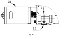
Fig. 4c is a schematic structural diagram of an aperture installed on the axis of a gearbox of a wire feeding motor in a light detection device of a rebar bundling machine inEmbodiment 1 of the present invention. -
Fig. 5 is a schematic structural diagram of a rebar bundling machine gun head after being installed inEmbodiment 1 of the present invention. -
Fig. 6 is a circuit schematic block diagram of a rebar bundling machine inEmbodiment 2 of the present invention. -
Fig. 7 is a circuit schematic block diagram of a rebar bundling machine in Embodiment 3 of the present invention. - The present invention is described in further detail below with reference to the embodiments and the accompanying figures, but the embodiments of the present invention are not limited thereto.
- This embodiment discloses a replaceable gun head of a rebar bundling machine, which includes a gun head information identification component provided on the gun head. After the gun head is installed on the rebar bundling machine, the gun head information identification component is connected to the main control unit of the rebar bundling machine. The main control unit obtains the gun head information through the gun head information identification component.
- As shown in
Fig. 1 , the gun head information identification component provided on the gun head in this embodiment isresistor 1. After the gun head is installed on the rebar bundling machine, one end of the resistor is connected to the main control unit of the rebar bundling machine, and the other end is grounded or powered. The main control unit obtains the gun head information by detecting the resistance value of the resistor. The gun head information may be a gun head caliber and / or a gun head model. In this embodiment, the gun head information is a gun head caliber. - In this embodiment, the resistance set on the gun head is selected according to the caliber of the gun head. The resistance on the gun head is 1 ~ 40KΩ, 50 ~ 80KΩ, 100 ~ 400KΩ, 560 ~ 820 KΩ, 1 ~ 2MΩ, 3 ~ 5 MΩ, 8 ~ 10MΩ, or 20 ~ 30MΩ; in this embodiment, a gun head with a diameter of 20mm uses a resistor of 1 ~ 40KΩ, a gun head with a diameter of 25mm uses a resistor of 50 ~ 80KΩ, a gun head with a diameter of 30mm uses a resistor of 100 ~ 400KΩ, a gun head with a diameter of 35mm uses a resistor of 560 ~ 820KΩ, a gun head with a diameter of 40mm uses a resistor of 1 ~ 2MΩ, a gun head with a diameter of 45mm uses a resistor of 3 ~ 5MΩ, a gun head with a diameter of 50mm uses a resistor of 8 ~ 10MΩ, and a gun head with a diameter of 60mm uses a resistor of 20 ~ 30MΩ. The main control unit records the relationship between the above-mentioned gun head caliber and resistance. When the main control unit detects the resistance value of the resistor on the gun head, it can obtain the corresponding gun head information, that is, the gun head caliber size information.
- After the gun head is installed on the rebar bundling machine, one end of the resistor is connected to the ADC sampling end of the main control unit of the rebar bundling machine, and the ADC sampling end collects the voltage on the resistor. The main control unit can identify the gun head information according to the resistance value of the resistor on the gun head, that is, to obtain the gun head caliber, so as to control the length and torque of the wire output by the gun head of the rebar bundling machine.
- This embodiment also discloses a rebar bundling machine, which includes a gun shell, a main control unit provided in the gun shell, and the above-mentioned replaceable gun head installed at the front end of the gun shell. As shown in
Fig. 2 , after installing the gun head at the front of the gun shell, one end of the resistor is connected to the main control unit, and the other end is grounded or powered; after installing the gun head at the front of the gun shell, one end of the resistor is connected to the main control unit, and the other end is grounded or powered. As shown inFig. 3 , the gun shell of the rebar bundling machine of the present embodiment, wherein the main control unit 3 is disposed on a main control board of a handheld portion of the gun shell. In this embodiment, the main control unit may use a single chip microcomputer. The gun head of this embodiment can be fixed on the front end of the gun shell by screws. - In this embodiment, a wire feeding motor, a wire twisting motor, a Hall element that senses the number of rotations of the wire feeding motor, and a current sampling device that collects the current value of the wire twisting motor are also arranged in the gun shell of the rebar bundling machine; as shown in the
Fig. 2 , the Hall element is connected to the main control unit, and the main control unit detects the number of rotations of the wire feeding motor through the Hall element. - In this embodiment, the number of rotations of the wire feeding motor can also be detected by a light detection device, where the light detection device includes an aperture and a photocoupler, as shown in
Fig. 4 , a plurality of equally-spaced light-transmitting grooves are set on the edge of the aperture, and the light-shielding part of the aperture is between each adjacent light-transmitting groove, in this embodiment, the number of light-transmitting grooves at the edge of the aperture is 30 or more. As shown inFig. 4b and4c , theaperture 22 is installed on the axis of thewire feeding motor 21 or the axis of the gearbox of the wire feeding motor, the edge of theaperture 22 extends between the light source and the receiver of thephotocoupler 23, the photocoupler connects to the main control unit; when the wire feeding motor rotates, the aperture is rotated, and when the aperture is rotated, the light-transmitting groove and the light-shielding part pass between the light source and the receiver of the photocoupler in order. Among them, when the light transmitting slot and the light shielding part of the aperture pass between the light source and the receiver of the photocoupler, the photocoupler will output high and low level signals to the main control unit, and the main control chip accurately judges the number of motor rotations by reading the high and low level change points of the photocoupler. In this embodiment, as shown inFig. 4b and4c , thephotocoupler 23 is U-shaped opening, wherein the light source is set on one side of the U-shaped opening, and the light receiver is set on the other side of the U-shaped opening. - The main control unit is connected to the wire feeding motor and the wire twisting motor through a motor driver and is used to control the rotation of the wire feeding motor and the wire twisting motor. In this embodiment, the wire feeding motor and the wire twisting motor of the rebar bundling machine are the same motor or two different motors, when the wire feeding motor and the wire twisting motor are the same one, the motor respectively performs wire feeding and twisting work at different time periods.
- The main control unit is connected to the wire twisting motor through the current sampling device and is used to judge the torque value of the wire twisting motor according to the current value of the wire twisting motor collected by the current sampling device.
- In this embodiment, the current collection device is a high-power second resistor, and the main control unit is connected to the current output terminal of the motor through the second resistor.
- As shown in
Fig. 3 , in this embodiment, the front end of the gun shell is provided with twocontact points 2, one of which is connected to the ADC sampling terminal of the main control unit, and the other contact point is grounded or powered. After amounting the gun head at the front end of the gun shell, the two ends of the resistor are connected to the two contact points respectively, as shown inFig. 5 , the rebar bundling machine after the gun head is installed at the front end of the gun shell. - In this embodiment, the main control unit is connected with a voice playback device for playing the gun head information. After acquiring the gun head information, the main control unit can play the gun head information through the voice playback device to remind the user of the rebar bundling machine Information such as the type and size of the gun head used.
- This embodiment also discloses a working method of the above-mentioned rebar bundling machine, the steps are as follows:
- Step S1, the main control unit sets the threshold of the number of rotations corresponding to the wire feeding motor for different gun head information; at the same time, the main control unit sets the torque threshold for the wire twisting motor for different gun head information;
in this embodiment, the main control unit can set the rotation number threshold corresponding to the wire feeding motor and the torque threshold corresponding to the wire twisting motor for gun heads of different calibers. - Step S2, after the gun head is mounted on the front end of the gun shell, the main control unit collects the voltage of the resistor on the gun head, determines the resistance value of the resistor on the gun head based on the voltage of the resistor on the gun head, and obtains
the corresponding gun head information according to the resistance value of the resistor, then obtains the threshold of the number of rotations of the wire feeding motor and the torque threshold of the wire twisting motor set for the gun head information. - Step S3, when the rebar bundling machine is in the process of wire feeding, the main control unit obtains the current number of rotations of the wire feeding motor in real time, when the current number of rotations of the motor reaches the above-mentioned threshold of the number of rotations of the wire feeding motor, the main control unit controls the wire feeding wire motor to stop rotating, and the gun head of the rebar bundling machine outputs a wire of corresponding length.
- When the rebar bundling machine is in the process of wire twisting, the main control unit collects the current value of the wire twisting motor in real time, and judges the current torque value of the wire twisting motor by the current value, when the current torque value of the wire twisting motor reaches the torque threshold of the wire twisting motor obtained above, the main control unit controls the wire feeding wire motor to stop rotating, and outputs the corresponding torque through the wire twisting motor.
- In this embodiment, when the rebar bundling machine is in the wire feeding process, the Hall element connected to the main control unit detects the current number of rotations of the wire feeding motor in real time, when the main control unit detects that the current number of rotations of the motor reaches the threshold value of the number of rotations of the wire feeding motor obtained through the Hall element, the wire feeding motor is controlled to stop rotation by the motor driver. Alternatively, when the rebar bundling machine is in the process of wire feeding, the main control unit detects the current number of rotations of the wire feeding motor in real time through the light detection device, when the main control unit detects that the current number of rotations of the motor reaches the threshold value of the number of rotations of the wire feeding motor obtained through the light detection device, the wire feeding motor is stopped by the motor driver.
- In this embodiment, when the rebar bundling machine is in the process of wire twisting, the current value of the wire twisting motor is collected in real time by a current acquisition device connected to the main control unit, then judge the current torque value of the wire twisting motor by the current value of the wire twisting motor collected by the current acquisition device, when the current torque value of the wire twisting motor reaches the torque threshold of the wire twisting motor obtained above, the main control unit controls the twisting motor to stop rotating, and the corresponding torque is output through the wire twisting motor.
- This embodiment discloses a replaceable gun head of a rebar bundling machine, which differs from
Embodiment 1 only in that, as shown inFig. 6 , the gun head information identification component provided on the gun head is an electronic tag storing gun head information, the electronic tag is connected to the main control unit of the rebar bundling machine through the electronic tag reader, and the main control unit obtains the gun head information through the electronic tag. The electronic tag may be an RFID electronic tag. - This embodiment also discloses a rebar bundling machine, which differs from the rebar bundling machine in
Embodiment 1 only in that the gun head of the bar bundling machine in this embodiment is the replaceable gun head described in this embodiment. An electronic tag reader is connected to the main control unit of the rebar bundling machine in this embodiment. After the gun head is installed on the rebar bundling machine, the main control unit reads the gun head information on the gun head electronic tag through the electronic tag reader. - This embodiment also discloses a working method of a rebar bundling machine, which differs from the working method of a rebar bundling machine in
Embodiment 1 only in that in this embodiment, the main control unit in step S2 directly reads the electronic tag on the gun head through the electronic tag reader, and thus reads the gun head information corresponding to the gun head to be installed on the rebar binding machine. - This embodiment discloses a replaceable gun head of a rebar bundling machine, which differs from
Embodiment 1 only in that, as shown inFig. 7 , the gun head information identification component provided on the gun head is a wireless communication slave module storing the gun head information in this embodiment, and the wireless communication slave module is connected to the rebar bundling machine through the wireless communication module; wherein, in this embodiment, the main control unit communicates with the wireless communication slave module on the gun head through the wireless communication module, in order to obtain the gun head information stored in the wireless communication slave module. - This embodiment also discloses a rebar bundling machine, which differs from the rebar bundling machine in
Embodiment 1 only in that the gun head of the rebar bundling machine in this embodiment is the replaceable gun head described in this embodiment. The main control unit of the rebar bundling machine in this embodiment is connected with a wireless communication module, and the main control unit communicates with the wireless communication slave module on the gun head through the wireless communication module, in order to read the gun head information stored in the wireless communication slave module on the gun head. The wireless communication module connected to the main control unit may be a communication module such as Bluetooth, WIFI or 2.4G. - This embodiment also discloses a working method of a rebar bundling machine, which differs from the working method of a rebar bundling machine in
Embodiment 1 only in that in this embodiment, the main control unit in step S2 communicates with the wireless communication slave module on the gun head through the wireless communication module, thereby obtaining gun head information. - The above embodiments are preferred embodiments of the present invention, but the embodiment of the present invention is not limited by the above embodiments. Any other changes, modifications, substitutions, combinations, and simplifications made without departing from the scope of the present invention , which is only defined by the appended claims, are included in the protection scope of the present invention.
Claims (9)
- A rebar bundling machine including a gun shell, a main control unit (3) set in the gun shell, a wire feeding motor (21) and a wire twisting motor set in the gun shell, and a gun head mounted on the front of the gun shell, the main control unit (3) is connected to the wire feeding motor (21) and the wire twisting motor through a motor driver, and is used to control the rotation of the wire feeding motor (21) and the wire twisting motor; the gun head is a replaceable gun head, characterized in that a gun head information identification component is provided on the gun head; after mounting the gun head on the rebar bundling machine, the gun head information identification component is connected to the main control unit (3) of the rebar bundling machine, and the main control unit (3) obtains gun head information through the gun head information identification component to identify a caliber of the gun head according to the gun head information, in order to control the wire length and torque output from the gun head of the rebar bundling machine.
- The rebar bundling machine according to claim 1, characterized by, the gun head information identification component provided on the gun head is a resistor (1), after mounting the gun head on the rebar bundling machine, one end of the resistor (1) is connected to the main control unit (3) of the rebar bundling machine, and the other end is grounded or powered; and the main control unit (3) obtains the gun head information by detecting the resistance value of the resistor (1).
- The rebar bundling machine according to claim 2, characterized by, a value of the resistor (1) provided on the gun head is selected according to the caliber of the gun head, and the value of the resistor (1) on the gun head is 1 ~ 40KΩ, 50 ~ 80KΩ, 100 ~ 400KΩ, 560 ~ 820 KΩ, 1 ~ 2MΩ, 3 ~ 5 MΩ, 8 ~ 10MΩ or 20 ~ 30MΩ; among them, after the gun head is installed on the rebar bundling machine, one end of the resistor (1) is connected to an ADC sampling terminal of the main control unit (3) of the rebar bundling machine, and the ADC sampling terminal collects a voltage across the resistor (1).
- The rebar bundling machine according to claim 1, characterized by, the gun head information identification component provided on the gun head is an electronic tag for storing gun head information, and the electronic tag provided on the gun head is connected to the main control unit (3) of the rebar bundling machine through an electronic tag reader, the main control unit (3) obtains the gun head information through the electronic tag.
- The rebar bundling machine according to claim 1, characterized by, the gun head information identification component provided on the gun head is a wireless communication slave module for storing gun head information, and the wireless communication slave module is connected to the main control unit (3) of the rebar bundling machine through a wireless communication module, the main control unit (3) obtains the gun head information from the wireless communication slave module through the wireless communication module.
- The rebar bundling machine according to claim 1, characterized by, further comprises a Hall element for detecting the number of turns of the wire feeding motor (21) and a current sampling device for collecting a current value of the wire twisting motor;the Hall element is connected to the main control unit (3);the main control unit (3) is connected to the wire twisting motor through the current sampling device and is configured to judge the torque value of the wire twisting motor according to the current value of the wire twisting motor collected by the current sampling device.
- The rebar bundling machine according to claim 1, characterized by, further comprises a light detection device for detecting the number of rotations of the wire feeding motor (21) and a current sampling device for collecting a current value of the wire twisting motor;the light detection device comprises an aperture (22) and a photocoupler (23), a plurality of equally spaced light-transmitting grooves are provided on an edge of the aperture (22), an aperture light-shielding portion is located between each adjacent light-transmitting groove, the aperture (22) is mounted on an axis of the wire feeding motor (21) or a gearbox axis of the wire feeding motor (21), the edge of the aperture (22) extends between a light source and a receiver of the photocoupler (23), and the photocoupler (23) is connected to the main control unit (3); when the wire feeding motor (21) rotates, the aperture (22) is rotated, and when the aperture (22) is rotated, the light-transmitting groove and the light-shielding part pass between the light source and the receiver of the photocoupler (23) in order;the main control unit (3) is connected to the wire twisting motor through the current sampling device and is configured to judge a torque value of the wire twisting motor according to the current value of the wire twisting motor collected by the current sampling device.
- A working method of a rebar bundling machine according to claim 1, characterized in that the steps are as follows:the main control unit (3) sets a rotation number threshold of the wire feeding motor (21) for the gun head according to different gun head information; at the same time, the main control unit (3) sets the torque threshold of the wire twisting motor for the gun head according to different gun head information;the main control unit (3) obtains the gun head information through the gun head information identification component, and then obtains the rotation number threshold of the wire feeding motor (21) and the torque threshold of the wire twisting motor set according to the gun head information;when the rebar bundling machine is in the process of wire feeding, the main control unit (3) obtains the current rotation number of the wire feeding motor (21) in real time; when the current rotation number of the motor reaches the rotation number threshold of the wire feeding motor (21) obtained above, the main control unit (3) controls the wire feeding wire motor to stop rotating, and the gun head of the rebar bundling machine outputs a wire of corresponding length;when the rebar bundling machine is in the process of wire twisting, the main control unit (3) collects a current value of the wire twisting motor in real time and judges the current torque value of the wire twisting motor by the current value; when the current torque value of the wire twisting motor reaches the torque threshold of the wire twisting motor obtained above, the main control unit (3) controls the wire twisting motor to stop rotating, and a corresponding torque is output through the wire twisting motor.
- A working method of a rebar bundling machine according to claim 1, characterized in that,when the gun head information identification component provided on the gun head is a resistor (1), after amounting the gun head at the front end of the gun shell, the main control unit (3) obtains the gun head information by detecting the value of the resistor (1) on the gun head;when the gun head information identification component provided on the gun head is an electronic tag for storing gun head information, the main control unit (3) reads the electronic tag on the gun head through the electronic tag reader, thereby reading the gun head information therein;when the gun head information identification component provided on the gun head is a wireless communication slave module for storing gun head information, the main control unit (3) communicates with the wireless communication slave module on the gun head through the wireless communication module, thereby obtaining the gun head information;when the rebar bundling machine is in the process of wire feeding, a Hall element connected to the main control unit (3) detects the current rotation number of the wire feeding motor (21) in real time, when the main control unit (3) detects that the current rotation number of the motor reaches the threshold value of the rotation number of the wire feeding motor (21) obtained through the Hall element, it stops the rotation of the wire feeding motor (21) through the motor driver; or, when the rebar bundling machine is in the process of wire feeding, the main control unit (3) detects the current rotation number of the wire feeding motor (21) in real time through the light detection device, when the main control unit (3) detects that the current rotation number of the motor reaches the above-mentioned threshold of the rotation number of the wire feeding motor (21) through the light detection device, controls the wire feeding motor (21) to stop rotating through the motor driver;when the rebar bundling machine is in the process of wire twisting, the current acquisition device that connected to the main control unit (3) collects a current value of the twisting motor in real time, and then the current torque value of the wire twisting motor is determined by the current value of the wire twisting motor collected by the current acquisition device, when the current torque value of the wire twisting motor reaches the obtained torque threshold of the wire twisting motor, the main control unit (3) controls the wire twisting motor to stop rotating, and outputs a corresponding torque through the wire twisting motor.
Applications Claiming Priority (2)
| Application Number | Priority Date | Filing Date | Title |
|---|---|---|---|
| CN201810412848.3A CN108343250B (en) | 2018-05-03 | 2018-05-03 | A kind of reinforcing-bar binding machine and its changeable type pipette tips and working method |
| PCT/CN2018/088828 WO2019210548A1 (en) | 2018-05-03 | 2018-05-29 | Steel bar strapping machine and replaceable gun head and operating method thereof |
Publications (3)
| Publication Number | Publication Date |
|---|---|
| EP3677736A1 EP3677736A1 (en) | 2020-07-08 |
| EP3677736A4 EP3677736A4 (en) | 2021-05-26 |
| EP3677736B1 true EP3677736B1 (en) | 2025-07-09 |
Family
ID=62955515
Family Applications (1)
| Application Number | Title | Priority Date | Filing Date |
|---|---|---|---|
| EP18917485.7A Active EP3677736B1 (en) | 2018-05-03 | 2018-05-29 | Steel bar strapping machine with a replaceable gun head and operating method thereof |
Country Status (4)
| Country | Link |
|---|---|
| US (1) | US12179947B2 (en) |
| EP (1) | EP3677736B1 (en) |
| CN (1) | CN108343250B (en) |
| WO (1) | WO2019210548A1 (en) |
Families Citing this family (13)
| Publication number | Priority date | Publication date | Assignee | Title |
|---|---|---|---|---|
| US20200030919A1 (en) * | 2018-07-25 | 2020-01-30 | Esab Ab | Automated welding system for interchangeable welding heads |
| CN108988581A (en) * | 2018-08-15 | 2018-12-11 | 广东顺德华焱电子科技有限公司 | Motor turnning circle detection device, method and reinforcing-bar binding machine |
| WO2020093380A1 (en) * | 2018-11-09 | 2020-05-14 | 广东顺德华焱电子科技有限公司 | Rebar bundling machine and bundling control device thereof and bundling control method therefor |
| CN109292139A (en) * | 2018-11-09 | 2019-02-01 | 广东顺德华焱电子科技有限公司 | It reinforcing-bar binding machine and its ties up and control device and ties up control method |
| US12559956B2 (en) | 2019-02-27 | 2026-02-24 | Kyocera Corporation | Rebar tying tool |
| CN110469127B (en) * | 2019-09-17 | 2024-07-05 | 广东顺德华焱电子科技有限公司 | Gun head of reinforcing steel bar bundling machine |
| CN111305577A (en) * | 2019-12-23 | 2020-06-19 | 广东顺德华焱电子科技有限公司 | Reinforcing steel bar binding machine |
| CN111576888B (en) * | 2020-06-19 | 2025-06-06 | 广东顺德华焱电子科技有限公司 | Communication type hands-free steel bar bundling machine and steel bar bundling automation equipment |
| CN112270476A (en) * | 2020-10-29 | 2021-01-26 | 广东顺德华焱电子科技有限公司 | Steel bar binding machine and monitoring method, system and storage medium thereof |
| CN113844725B (en) * | 2021-09-18 | 2023-03-07 | 台州市新大陆电子科技有限公司 | Intelligent binding machine |
| CN115709831B (en) * | 2022-12-16 | 2026-01-02 | 台州市新大陆电子科技有限公司 | An automatic wire feeding and bundling machine based on electrical signals and a wire feeding control method. |
| EP4398206B1 (en) * | 2023-01-05 | 2025-06-11 | TITAN Umreifungstechnik GmbH & Co.KG | Strapping band device |
| WO2024173107A1 (en) * | 2023-02-16 | 2024-08-22 | Signode Industrial Group Llc | Strapping machine with a device-identifying module |
Family Cites Families (17)
| Publication number | Priority date | Publication date | Assignee | Title |
|---|---|---|---|---|
| DE10118034B4 (en) * | 2001-04-11 | 2006-01-26 | Robert Bosch Gmbh | Machine tool that can be coupled with different tool holders |
| US7069962B2 (en) * | 2004-08-27 | 2006-07-04 | Dara Cheng | Wire cutting and twisting tool with spool assembly and manual wire feeding mechanism |
| JP4978088B2 (en) | 2006-07-24 | 2012-07-18 | マックス株式会社 | Method for preventing wire thread breakage in reinforcing bar binding machine |
| EP2757211B1 (en) * | 2008-05-19 | 2019-01-09 | Max Co., Ltd. | Brake system of wire reel in reinforcing bar binding machine |
| KR100910027B1 (en) * | 2009-03-05 | 2009-07-30 | 이동천 | Rebar Binding Line Strap |
| US9395715B2 (en) * | 2012-04-04 | 2016-07-19 | Hypertherm, Inc. | Identifying components in a material processing system |
| JP6451184B2 (en) | 2014-09-30 | 2019-01-16 | マックス株式会社 | Rebar binding machine |
| CN204383801U (en) * | 2014-12-17 | 2015-06-10 | 佛山市立澜建筑材料有限公司 | A kind of reinforcing-bar binding machine |
| US20160201342A1 (en) * | 2015-01-14 | 2016-07-14 | Luther Sivadjian | Rebar Joint Tie Tool |
| CN104943896B (en) * | 2015-06-18 | 2017-02-22 | 苏州律力电子科技有限公司 | Circuit control system for steel bar bundling machine |
| JP6530990B2 (en) | 2015-07-13 | 2019-06-12 | 株式会社マキタ | Rebar binding device |
| JP3210812U (en) * | 2017-03-28 | 2017-06-08 | 株式会社沢田鉄筋 | Thick wire tightening jig for rotary tools |
| CN107165416A (en) | 2017-05-23 | 2017-09-15 | 成都智诚利合科技有限公司 | A kind of intelligent knot installation of the embedded bar of building concrete |
| CN107165417A (en) * | 2017-05-23 | 2017-09-15 | 成都智诚利合科技有限公司 | The control system of embedded bar knot installation in a kind of concrete |
| CN107161375B (en) * | 2017-06-13 | 2019-11-22 | 台州市新大陆电子科技有限公司 | Method for controlling the number of binding circles of steel bar binding machine and steel bar binding machine |
| CN208168382U (en) * | 2018-05-03 | 2018-11-30 | 广东顺德华焱电子科技有限公司 | A kind of reinforcing-bar binding machine and its changeable type pipette tips |
| WO2020093380A1 (en) | 2018-11-09 | 2020-05-14 | 广东顺德华焱电子科技有限公司 | Rebar bundling machine and bundling control device thereof and bundling control method therefor |
-
2018
- 2018-05-03 CN CN201810412848.3A patent/CN108343250B/en active Active
- 2018-05-29 WO PCT/CN2018/088828 patent/WO2019210548A1/en not_active Ceased
- 2018-05-29 EP EP18917485.7A patent/EP3677736B1/en active Active
- 2018-05-29 US US17/047,459 patent/US12179947B2/en active Active
Also Published As
| Publication number | Publication date |
|---|---|
| CN108343250A (en) | 2018-07-31 |
| EP3677736A1 (en) | 2020-07-08 |
| US12179947B2 (en) | 2024-12-31 |
| WO2019210548A1 (en) | 2019-11-07 |
| US20210155357A1 (en) | 2021-05-27 |
| EP3677736A4 (en) | 2021-05-26 |
| CN108343250B (en) | 2019-06-18 |
Similar Documents
| Publication | Publication Date | Title |
|---|---|---|
| EP3677736A1 (en) | Steel bar strapping machine and replaceable gun head and operating method thereof | |
| CN104808584A (en) | Multi-information online detection system for machine tool multi-source energy consumption system | |
| DE102011089499A1 (en) | Mobile communication device for large battery of machine tool, has communication link for unidirectional or bidirectional exchange of data with accumulator, and receptacle for identification module | |
| CN105894782A (en) | Metering automation meter-reading system for offline user acquisition terminal | |
| CN113938765A (en) | Electric energy metering data uploading processing method and system | |
| CN100568310C (en) | A meter reading method, system and user terminal device for an electric energy meter | |
| CN207219047U (en) | The managing device and system of instrument and equipment | |
| CN208168382U (en) | A kind of reinforcing-bar binding machine and its changeable type pipette tips | |
| CN110109043A (en) | Electric energy meter detection method, detection terminal and computer readable storage medium | |
| CN205139693U (en) | Digital control processing cutter management information collection system | |
| CN115000887B (en) | Insulated wire stripper, fixed-length stripping control method and controller | |
| CN109900308A (en) | A kind of sensor it is artificial than examining system and its method | |
| CN207082012U (en) | A kind of numerical control device machining information acquisition system | |
| CN111145539A (en) | Traffic information data collection system and method based on ARM processor | |
| CN103105823A (en) | System and method for information wireless transmission of feeding and blanking robots and numerically-controlled machine tool groups | |
| CN214896318U (en) | Intelligent management system for equipment state | |
| CN212285660U (en) | Reinforcing bar monitoring mechanism | |
| CN212134727U (en) | A CAN bus-based device for measuring working conditions of rotating tools of alfalfa harvester | |
| CN108988581A (en) | Motor turnning circle detection device, method and reinforcing-bar binding machine | |
| CN212505222U (en) | Device and system for improving effective distance measurement capability of single-spindle detection of ring spinning | |
| CN210271257U (en) | An easy-to-install multi-sensor parking space detection device | |
| CN221550781U (en) | Ammeter electric quantity acquisition terminal | |
| CN202362642U (en) | Machine tool operation monitoring device | |
| CN112059063A (en) | Reinforcing bar monitoring mechanism | |
| CN116389942A (en) | A general data acquisition device for engineering monitoring sensors |
Legal Events
| Date | Code | Title | Description |
|---|---|---|---|
| STAA | Information on the status of an ep patent application or granted ep patent |
Free format text: STATUS: THE INTERNATIONAL PUBLICATION HAS BEEN MADE |
|
| PUAI | Public reference made under article 153(3) epc to a published international application that has entered the european phase |
Free format text: ORIGINAL CODE: 0009012 |
|
| STAA | Information on the status of an ep patent application or granted ep patent |
Free format text: STATUS: REQUEST FOR EXAMINATION WAS MADE |
|
| 17P | Request for examination filed |
Effective date: 20200329 |
|
| AK | Designated contracting states |
Kind code of ref document: A1 Designated state(s): AL AT BE BG CH CY CZ DE DK EE ES FI FR GB GR HR HU IE IS IT LI LT LU LV MC MK MT NL NO PL PT RO RS SE SI SK SM TR |
|
| AX | Request for extension of the european patent |
Extension state: BA ME |
|
| A4 | Supplementary search report drawn up and despatched |
Effective date: 20210428 |
|
| RIC1 | Information provided on ipc code assigned before grant |
Ipc: E04G 21/12 20060101AFI20210421BHEP Ipc: B65B 13/18 20060101ALI20210421BHEP Ipc: B25F 3/00 20060101ALI20210421BHEP |
|
| DAV | Request for validation of the european patent (deleted) | ||
| DAX | Request for extension of the european patent (deleted) | ||
| STAA | Information on the status of an ep patent application or granted ep patent |
Free format text: STATUS: EXAMINATION IS IN PROGRESS |
|
| 17Q | First examination report despatched |
Effective date: 20240402 |
|
| GRAP | Despatch of communication of intention to grant a patent |
Free format text: ORIGINAL CODE: EPIDOSNIGR1 |
|
| STAA | Information on the status of an ep patent application or granted ep patent |
Free format text: STATUS: GRANT OF PATENT IS INTENDED |
|
| INTG | Intention to grant announced |
Effective date: 20241217 |
|
| RIC1 | Information provided on ipc code assigned before grant |
Ipc: B25F 3/00 20060101ALI20241209BHEP Ipc: B25F 5/00 20060101ALI20241209BHEP Ipc: E04G 21/12 20060101AFI20241209BHEP |
|
| GRAS | Grant fee paid |
Free format text: ORIGINAL CODE: EPIDOSNIGR3 |
|
| GRAA | (expected) grant |
Free format text: ORIGINAL CODE: 0009210 |
|
| STAA | Information on the status of an ep patent application or granted ep patent |
Free format text: STATUS: THE PATENT HAS BEEN GRANTED |
|
| AK | Designated contracting states |
Kind code of ref document: B1 Designated state(s): AL AT BE BG CH CY CZ DE DK EE ES FI FR GB GR HR HU IE IS IT LI LT LU LV MC MK MT NL NO PL PT RO RS SE SI SK SM TR |
|
| REG | Reference to a national code |
Ref country code: GB Ref legal event code: FG4D |
|
| REG | Reference to a national code |
Ref country code: CH Ref legal event code: EP |
|
| REG | Reference to a national code |
Ref country code: IE Ref legal event code: FG4D |
|
| REG | Reference to a national code |
Ref country code: DE Ref legal event code: R096 Ref document number: 602018083518 Country of ref document: DE |
|
| REG | Reference to a national code |
Ref country code: NL Ref legal event code: MP Effective date: 20250709 |
|
| PG25 | Lapsed in a contracting state [announced via postgrant information from national office to epo] |
Ref country code: PT Free format text: LAPSE BECAUSE OF FAILURE TO SUBMIT A TRANSLATION OF THE DESCRIPTION OR TO PAY THE FEE WITHIN THE PRESCRIBED TIME-LIMIT Effective date: 20251110 |
|
| PG25 | Lapsed in a contracting state [announced via postgrant information from national office to epo] |
Ref country code: NL Free format text: LAPSE BECAUSE OF FAILURE TO SUBMIT A TRANSLATION OF THE DESCRIPTION OR TO PAY THE FEE WITHIN THE PRESCRIBED TIME-LIMIT Effective date: 20250709 |
|
| REG | Reference to a national code |
Ref country code: AT Ref legal event code: MK05 Ref document number: 1811955 Country of ref document: AT Kind code of ref document: T Effective date: 20250709 |
|
| PG25 | Lapsed in a contracting state [announced via postgrant information from national office to epo] |
Ref country code: IS Free format text: LAPSE BECAUSE OF FAILURE TO SUBMIT A TRANSLATION OF THE DESCRIPTION OR TO PAY THE FEE WITHIN THE PRESCRIBED TIME-LIMIT Effective date: 20251109 |
|
| PG25 | Lapsed in a contracting state [announced via postgrant information from national office to epo] |
Ref country code: NO Free format text: LAPSE BECAUSE OF FAILURE TO SUBMIT A TRANSLATION OF THE DESCRIPTION OR TO PAY THE FEE WITHIN THE PRESCRIBED TIME-LIMIT Effective date: 20251009 |
|
| REG | Reference to a national code |
Ref country code: LT Ref legal event code: MG9D |
|
| PG25 | Lapsed in a contracting state [announced via postgrant information from national office to epo] |
Ref country code: AT Free format text: LAPSE BECAUSE OF FAILURE TO SUBMIT A TRANSLATION OF THE DESCRIPTION OR TO PAY THE FEE WITHIN THE PRESCRIBED TIME-LIMIT Effective date: 20250709 |
|
| PG25 | Lapsed in a contracting state [announced via postgrant information from national office to epo] |
Ref country code: FI Free format text: LAPSE BECAUSE OF FAILURE TO SUBMIT A TRANSLATION OF THE DESCRIPTION OR TO PAY THE FEE WITHIN THE PRESCRIBED TIME-LIMIT Effective date: 20250709 |
|
| PG25 | Lapsed in a contracting state [announced via postgrant information from national office to epo] |
Ref country code: HR Free format text: LAPSE BECAUSE OF FAILURE TO SUBMIT A TRANSLATION OF THE DESCRIPTION OR TO PAY THE FEE WITHIN THE PRESCRIBED TIME-LIMIT Effective date: 20250709 |
|
| PG25 | Lapsed in a contracting state [announced via postgrant information from national office to epo] |
Ref country code: GR Free format text: LAPSE BECAUSE OF FAILURE TO SUBMIT A TRANSLATION OF THE DESCRIPTION OR TO PAY THE FEE WITHIN THE PRESCRIBED TIME-LIMIT Effective date: 20251010 |
|
| PG25 | Lapsed in a contracting state [announced via postgrant information from national office to epo] |
Ref country code: SE Free format text: LAPSE BECAUSE OF FAILURE TO SUBMIT A TRANSLATION OF THE DESCRIPTION OR TO PAY THE FEE WITHIN THE PRESCRIBED TIME-LIMIT Effective date: 20250709 |
|
| PG25 | Lapsed in a contracting state [announced via postgrant information from national office to epo] |
Ref country code: LV Free format text: LAPSE BECAUSE OF FAILURE TO SUBMIT A TRANSLATION OF THE DESCRIPTION OR TO PAY THE FEE WITHIN THE PRESCRIBED TIME-LIMIT Effective date: 20250709 |
|
| PG25 | Lapsed in a contracting state [announced via postgrant information from national office to epo] |
Ref country code: PL Free format text: LAPSE BECAUSE OF FAILURE TO SUBMIT A TRANSLATION OF THE DESCRIPTION OR TO PAY THE FEE WITHIN THE PRESCRIBED TIME-LIMIT Effective date: 20250709 Ref country code: BG Free format text: LAPSE BECAUSE OF FAILURE TO SUBMIT A TRANSLATION OF THE DESCRIPTION OR TO PAY THE FEE WITHIN THE PRESCRIBED TIME-LIMIT Effective date: 20250709 |
|
| PG25 | Lapsed in a contracting state [announced via postgrant information from national office to epo] |
Ref country code: RS Free format text: LAPSE BECAUSE OF FAILURE TO SUBMIT A TRANSLATION OF THE DESCRIPTION OR TO PAY THE FEE WITHIN THE PRESCRIBED TIME-LIMIT Effective date: 20251009 |
|
| PG25 | Lapsed in a contracting state [announced via postgrant information from national office to epo] |
Ref country code: ES Free format text: LAPSE BECAUSE OF FAILURE TO SUBMIT A TRANSLATION OF THE DESCRIPTION OR TO PAY THE FEE WITHIN THE PRESCRIBED TIME-LIMIT Effective date: 20250709 |
|
| PG25 | Lapsed in a contracting state [announced via postgrant information from national office to epo] |
Ref country code: SM Free format text: LAPSE BECAUSE OF FAILURE TO SUBMIT A TRANSLATION OF THE DESCRIPTION OR TO PAY THE FEE WITHIN THE PRESCRIBED TIME-LIMIT Effective date: 20250709 |
|
| PG25 | Lapsed in a contracting state [announced via postgrant information from national office to epo] |
Ref country code: DK Free format text: LAPSE BECAUSE OF FAILURE TO SUBMIT A TRANSLATION OF THE DESCRIPTION OR TO PAY THE FEE WITHIN THE PRESCRIBED TIME-LIMIT Effective date: 20250709 |
|
| PG25 | Lapsed in a contracting state [announced via postgrant information from national office to epo] |
Ref country code: IT Free format text: LAPSE BECAUSE OF FAILURE TO SUBMIT A TRANSLATION OF THE DESCRIPTION OR TO PAY THE FEE WITHIN THE PRESCRIBED TIME-LIMIT Effective date: 20250709 |
|
| PG25 | Lapsed in a contracting state [announced via postgrant information from national office to epo] |
Ref country code: CZ Free format text: LAPSE BECAUSE OF FAILURE TO SUBMIT A TRANSLATION OF THE DESCRIPTION OR TO PAY THE FEE WITHIN THE PRESCRIBED TIME-LIMIT Effective date: 20250709 |
|
| PG25 | Lapsed in a contracting state [announced via postgrant information from national office to epo] |
Ref country code: SK Free format text: LAPSE BECAUSE OF FAILURE TO SUBMIT A TRANSLATION OF THE DESCRIPTION OR TO PAY THE FEE WITHIN THE PRESCRIBED TIME-LIMIT Effective date: 20250709 Ref country code: EE Free format text: LAPSE BECAUSE OF FAILURE TO SUBMIT A TRANSLATION OF THE DESCRIPTION OR TO PAY THE FEE WITHIN THE PRESCRIBED TIME-LIMIT Effective date: 20250709 |
|
| PLBE | No opposition filed within time limit |
Free format text: ORIGINAL CODE: 0009261 |
|
| STAA | Information on the status of an ep patent application or granted ep patent |
Free format text: STATUS: NO OPPOSITION FILED WITHIN TIME LIMIT |