EP3677439A1 - Pneumatic tire - Google Patents
Pneumatic tire Download PDFInfo
- Publication number
- EP3677439A1 EP3677439A1 EP18856858.8A EP18856858A EP3677439A1 EP 3677439 A1 EP3677439 A1 EP 3677439A1 EP 18856858 A EP18856858 A EP 18856858A EP 3677439 A1 EP3677439 A1 EP 3677439A1
- Authority
- EP
- European Patent Office
- Prior art keywords
- tire
- mass
- electronic component
- parts
- rubber
- Prior art date
- Legal status (The legal status is an assumption and is not a legal conclusion. Google has not performed a legal analysis and makes no representation as to the accuracy of the status listed.)
- Granted
Links
- 229920001971 elastomer Polymers 0.000 claims abstract description 70
- 239000005060 rubber Substances 0.000 claims abstract description 70
- VYPSYNLAJGMNEJ-UHFFFAOYSA-N Silicium dioxide Chemical compound O=[Si]=O VYPSYNLAJGMNEJ-UHFFFAOYSA-N 0.000 claims abstract description 68
- 239000000377 silicon dioxide Substances 0.000 claims abstract description 33
- 239000011324 bead Substances 0.000 claims description 24
- 230000007423 decrease Effects 0.000 abstract description 5
- 238000005516 engineering process Methods 0.000 abstract description 3
- 239000000203 mixture Substances 0.000 description 25
- 238000004073 vulcanization Methods 0.000 description 21
- 239000005062 Polybutadiene Substances 0.000 description 18
- 229920002857 polybutadiene Polymers 0.000 description 18
- NINIDFKCEFEMDL-UHFFFAOYSA-N Sulfur Chemical compound [S] NINIDFKCEFEMDL-UHFFFAOYSA-N 0.000 description 13
- 239000003795 chemical substances by application Substances 0.000 description 13
- 229910052717 sulfur Inorganic materials 0.000 description 13
- 239000011593 sulfur Substances 0.000 description 13
- XLOMVQKBTHCTTD-UHFFFAOYSA-N Zinc monoxide Chemical compound [Zn]=O XLOMVQKBTHCTTD-UHFFFAOYSA-N 0.000 description 12
- 238000009472 formulation Methods 0.000 description 11
- 229920003049 isoprene rubber Polymers 0.000 description 11
- 244000043261 Hevea brasiliensis Species 0.000 description 10
- CBENFWSGALASAD-UHFFFAOYSA-N Ozone Chemical compound [O-][O+]=O CBENFWSGALASAD-UHFFFAOYSA-N 0.000 description 10
- 238000004891 communication Methods 0.000 description 10
- 230000000694 effects Effects 0.000 description 10
- 229920003052 natural elastomer Polymers 0.000 description 10
- 229920001194 natural rubber Polymers 0.000 description 10
- 239000003921 oil Substances 0.000 description 10
- 230000003712 anti-aging effect Effects 0.000 description 9
- 238000000034 method Methods 0.000 description 9
- 235000019198 oils Nutrition 0.000 description 9
- 239000001993 wax Substances 0.000 description 9
- ZRALSGWEFCBTJO-UHFFFAOYSA-N Guanidine Chemical compound NC(N)=N ZRALSGWEFCBTJO-UHFFFAOYSA-N 0.000 description 8
- 238000013329 compounding Methods 0.000 description 8
- 239000000463 material Substances 0.000 description 8
- 239000006087 Silane Coupling Agent Substances 0.000 description 7
- 235000021355 Stearic acid Nutrition 0.000 description 7
- 239000006229 carbon black Substances 0.000 description 7
- QIQXTHQIDYTFRH-UHFFFAOYSA-N octadecanoic acid Chemical compound CCCCCCCCCCCCCCCCCC(O)=O QIQXTHQIDYTFRH-UHFFFAOYSA-N 0.000 description 7
- OQCDKBAXFALNLD-UHFFFAOYSA-N octadecanoic acid Natural products CCCCCCCC(C)CCCCCCCCC(O)=O OQCDKBAXFALNLD-UHFFFAOYSA-N 0.000 description 7
- 239000008117 stearic acid Substances 0.000 description 7
- DMBHHRLKUKUOEG-UHFFFAOYSA-N diphenylamine Chemical compound C=1C=CC=CC=1NC1=CC=CC=C1 DMBHHRLKUKUOEG-UHFFFAOYSA-N 0.000 description 6
- 238000011156 evaluation Methods 0.000 description 6
- 239000011787 zinc oxide Substances 0.000 description 6
- -1 glycidoxy Chemical group 0.000 description 5
- 238000004519 manufacturing process Methods 0.000 description 5
- 238000000465 moulding Methods 0.000 description 5
- 239000010734 process oil Substances 0.000 description 5
- 239000012779 reinforcing material Substances 0.000 description 5
- 239000000126 substance Substances 0.000 description 5
- CHJJGSNFBQVOTG-UHFFFAOYSA-N N-methyl-guanidine Natural products CNC(N)=N CHJJGSNFBQVOTG-UHFFFAOYSA-N 0.000 description 4
- SWSQBOPZIKWTGO-UHFFFAOYSA-N dimethylaminoamidine Natural products CN(C)C(N)=N SWSQBOPZIKWTGO-UHFFFAOYSA-N 0.000 description 4
- 239000003981 vehicle Substances 0.000 description 4
- OPNUROKCUBTKLF-UHFFFAOYSA-N 1,2-bis(2-methylphenyl)guanidine Chemical compound CC1=CC=CC=C1N\C(N)=N\C1=CC=CC=C1C OPNUROKCUBTKLF-UHFFFAOYSA-N 0.000 description 3
- OWRCNXZUPFZXOS-UHFFFAOYSA-N 1,3-diphenylguanidine Chemical compound C=1C=CC=CC=1NC(=N)NC1=CC=CC=C1 OWRCNXZUPFZXOS-UHFFFAOYSA-N 0.000 description 3
- 238000005452 bending Methods 0.000 description 3
- 238000006243 chemical reaction Methods 0.000 description 3
- 230000000052 comparative effect Effects 0.000 description 3
- 230000006870 function Effects 0.000 description 3
- 230000036571 hydration Effects 0.000 description 3
- 238000006703 hydration reaction Methods 0.000 description 3
- 238000005259 measurement Methods 0.000 description 3
- XLYOFNOQVPJJNP-UHFFFAOYSA-N water Substances O XLYOFNOQVPJJNP-UHFFFAOYSA-N 0.000 description 3
- SQZCAOHYQSOZCE-UHFFFAOYSA-N 1-(diaminomethylidene)-2-(2-methylphenyl)guanidine Chemical compound CC1=CC=CC=C1N=C(N)N=C(N)N SQZCAOHYQSOZCE-UHFFFAOYSA-N 0.000 description 2
- VTYYLEPIZMXCLO-UHFFFAOYSA-L Calcium carbonate Chemical compound [Ca+2].[O-]C([O-])=O VTYYLEPIZMXCLO-UHFFFAOYSA-L 0.000 description 2
- OKTJSMMVPCPJKN-UHFFFAOYSA-N Carbon Chemical compound [C] OKTJSMMVPCPJKN-UHFFFAOYSA-N 0.000 description 2
- RRHGJUQNOFWUDK-UHFFFAOYSA-N Isoprene Chemical compound CC(=C)C=C RRHGJUQNOFWUDK-UHFFFAOYSA-N 0.000 description 2
- 241000254043 Melolonthinae Species 0.000 description 2
- OUBMGJOQLXMSNT-UHFFFAOYSA-N N-isopropyl-N'-phenyl-p-phenylenediamine Chemical compound C1=CC(NC(C)C)=CC=C1NC1=CC=CC=C1 OUBMGJOQLXMSNT-UHFFFAOYSA-N 0.000 description 2
- 229920000459 Nitrile rubber Polymers 0.000 description 2
- UCKMPCXJQFINFW-UHFFFAOYSA-N Sulphide Chemical compound [S-2] UCKMPCXJQFINFW-UHFFFAOYSA-N 0.000 description 2
- 230000001133 acceleration Effects 0.000 description 2
- 229920005549 butyl rubber Polymers 0.000 description 2
- 239000010495 camellia oil Substances 0.000 description 2
- 229910052799 carbon Inorganic materials 0.000 description 2
- 239000013078 crystal Substances 0.000 description 2
- 238000001125 extrusion Methods 0.000 description 2
- 239000000446 fuel Substances 0.000 description 2
- 125000000524 functional group Chemical group 0.000 description 2
- 238000004898 kneading Methods 0.000 description 2
- 238000005065 mining Methods 0.000 description 2
- 239000012188 paraffin wax Substances 0.000 description 2
- 229920001084 poly(chloroprene) Polymers 0.000 description 2
- 230000001737 promoting effect Effects 0.000 description 2
- RMAQACBXLXPBSY-UHFFFAOYSA-N silicic acid Chemical compound O[Si](O)(O)O RMAQACBXLXPBSY-UHFFFAOYSA-N 0.000 description 2
- 235000012239 silicon dioxide Nutrition 0.000 description 2
- 238000012360 testing method Methods 0.000 description 2
- UMGDCJDMYOKAJW-UHFFFAOYSA-N thiourea Chemical compound NC(N)=S UMGDCJDMYOKAJW-UHFFFAOYSA-N 0.000 description 2
- 235000015112 vegetable and seed oil Nutrition 0.000 description 2
- 235000019871 vegetable fat Nutrition 0.000 description 2
- KCNBAUKGODRNGM-UHFFFAOYSA-N 1,2-bis(2-propan-2-ylphenyl)guanidine Chemical compound CC(C)C1=CC=CC=C1NC(=N)NC1=CC=CC=C1C(C)C KCNBAUKGODRNGM-UHFFFAOYSA-N 0.000 description 1
- GEYOCULIXLDCMW-UHFFFAOYSA-N 1,2-phenylenediamine Chemical compound NC1=CC=CC=C1N GEYOCULIXLDCMW-UHFFFAOYSA-N 0.000 description 1
- CBCKQZAAMUWICA-UHFFFAOYSA-N 1,4-phenylenediamine Chemical compound NC1=CC=C(N)C=C1 CBCKQZAAMUWICA-UHFFFAOYSA-N 0.000 description 1
- UJPKMTDFFUTLGM-UHFFFAOYSA-N 1-aminoethanol Chemical compound CC(N)O UJPKMTDFFUTLGM-UHFFFAOYSA-N 0.000 description 1
- VETPHHXZEJAYOB-UHFFFAOYSA-N 1-n,4-n-dinaphthalen-2-ylbenzene-1,4-diamine Chemical compound C1=CC=CC2=CC(NC=3C=CC(NC=4C=C5C=CC=CC5=CC=4)=CC=3)=CC=C21 VETPHHXZEJAYOB-UHFFFAOYSA-N 0.000 description 1
- RUFPHBVGCFYCNW-UHFFFAOYSA-N 1-naphthylamine Chemical compound C1=CC=C2C(N)=CC=CC2=C1 RUFPHBVGCFYCNW-UHFFFAOYSA-N 0.000 description 1
- ZZMVLMVFYMGSMY-UHFFFAOYSA-N 4-n-(4-methylpentan-2-yl)-1-n-phenylbenzene-1,4-diamine Chemical compound C1=CC(NC(C)CC(C)C)=CC=C1NC1=CC=CC=C1 ZZMVLMVFYMGSMY-UHFFFAOYSA-N 0.000 description 1
- RSWGJHLUYNHPMX-UHFFFAOYSA-N Abietic-Saeure Natural products C12CCC(C(C)C)=CC2=CCC2C1(C)CCCC2(C)C(O)=O RSWGJHLUYNHPMX-UHFFFAOYSA-N 0.000 description 1
- BTBUEUYNUDRHOZ-UHFFFAOYSA-N Borate Chemical compound [O-]B([O-])[O-] BTBUEUYNUDRHOZ-UHFFFAOYSA-N 0.000 description 1
- 229920003043 Cellulose fiber Polymers 0.000 description 1
- VGGSQFUCUMXWEO-UHFFFAOYSA-N Ethene Chemical compound C=C VGGSQFUCUMXWEO-UHFFFAOYSA-N 0.000 description 1
- 239000005977 Ethylene Substances 0.000 description 1
- 235000018330 Macadamia integrifolia Nutrition 0.000 description 1
- 240000000912 Macadamia tetraphylla Species 0.000 description 1
- 235000003800 Macadamia tetraphylla Nutrition 0.000 description 1
- XQVWYOYUZDUNRW-UHFFFAOYSA-N N-Phenyl-1-naphthylamine Chemical compound C=1C=CC2=CC=CC=C2C=1NC1=CC=CC=C1 XQVWYOYUZDUNRW-UHFFFAOYSA-N 0.000 description 1
- UFWIBTONFRDIAS-UHFFFAOYSA-N Naphthalene Chemical compound C1=CC=CC2=CC=CC=C21 UFWIBTONFRDIAS-UHFFFAOYSA-N 0.000 description 1
- 240000007594 Oryza sativa Species 0.000 description 1
- 235000007164 Oryza sativa Nutrition 0.000 description 1
- 235000019482 Palm oil Nutrition 0.000 description 1
- 241000282320 Panthera leo Species 0.000 description 1
- 235000019483 Peanut oil Nutrition 0.000 description 1
- 235000019484 Rapeseed oil Nutrition 0.000 description 1
- KHPCPRHQVVSZAH-HUOMCSJISA-N Rosin Natural products O(C/C=C/c1ccccc1)[C@H]1[C@H](O)[C@@H](O)[C@@H](O)[C@@H](CO)O1 KHPCPRHQVVSZAH-HUOMCSJISA-N 0.000 description 1
- 235000019486 Sunflower oil Nutrition 0.000 description 1
- FZWLAAWBMGSTSO-UHFFFAOYSA-N Thiazole Chemical compound C1=CSC=N1 FZWLAAWBMGSTSO-UHFFFAOYSA-N 0.000 description 1
- XSQUKJJJFZCRTK-UHFFFAOYSA-N Urea Natural products NC(N)=O XSQUKJJJFZCRTK-UHFFFAOYSA-N 0.000 description 1
- 239000000654 additive Substances 0.000 description 1
- 230000000996 additive effect Effects 0.000 description 1
- 229920006223 adhesive resin Polymers 0.000 description 1
- 239000004840 adhesive resin Substances 0.000 description 1
- 150000001412 amines Chemical class 0.000 description 1
- 239000012164 animal wax Substances 0.000 description 1
- 230000005540 biological transmission Effects 0.000 description 1
- 239000004305 biphenyl Substances 0.000 description 1
- 229910000019 calcium carbonate Inorganic materials 0.000 description 1
- DKVNPHBNOWQYFE-UHFFFAOYSA-N carbamodithioic acid Chemical compound NC(S)=S DKVNPHBNOWQYFE-UHFFFAOYSA-N 0.000 description 1
- 239000004359 castor oil Substances 0.000 description 1
- 235000019438 castor oil Nutrition 0.000 description 1
- 125000001309 chloro group Chemical group Cl* 0.000 description 1
- 239000011248 coating agent Substances 0.000 description 1
- 238000000576 coating method Methods 0.000 description 1
- 239000008119 colloidal silica Substances 0.000 description 1
- 150000001875 compounds Chemical class 0.000 description 1
- 235000005687 corn oil Nutrition 0.000 description 1
- 239000002285 corn oil Substances 0.000 description 1
- 235000012343 cottonseed oil Nutrition 0.000 description 1
- 239000002385 cottonseed oil Substances 0.000 description 1
- 239000007822 coupling agent Substances 0.000 description 1
- 239000003431 cross linking reagent Substances 0.000 description 1
- 230000006866 deterioration Effects 0.000 description 1
- 229920003244 diene elastomer Polymers 0.000 description 1
- 235000014113 dietary fatty acids Nutrition 0.000 description 1
- 238000006073 displacement reaction Methods 0.000 description 1
- WSUTUEIGSOWBJO-UHFFFAOYSA-N dizinc oxygen(2-) Chemical compound [O-2].[O-2].[Zn+2].[Zn+2] WSUTUEIGSOWBJO-UHFFFAOYSA-N 0.000 description 1
- ZOOODBUHSVUZEM-UHFFFAOYSA-N ethoxymethanedithioic acid Chemical compound CCOC(S)=S ZOOODBUHSVUZEM-UHFFFAOYSA-N 0.000 description 1
- 238000002474 experimental method Methods 0.000 description 1
- 239000003925 fat Substances 0.000 description 1
- 239000000194 fatty acid Substances 0.000 description 1
- 229930195729 fatty acid Natural products 0.000 description 1
- ZEMPKEQAKRGZGQ-XOQCFJPHSA-N glycerol triricinoleate Natural products CCCCCC[C@@H](O)CC=CCCCCCCCC(=O)OC[C@@H](COC(=O)CCCCCCCC=CC[C@@H](O)CCCCCC)OC(=O)CCCCCCCC=CC[C@H](O)CCCCCC ZEMPKEQAKRGZGQ-XOQCFJPHSA-N 0.000 description 1
- 230000020169 heat generation Effects 0.000 description 1
- MTNDZQHUAFNZQY-UHFFFAOYSA-N imidazoline Chemical compound C1CN=CN1 MTNDZQHUAFNZQY-UHFFFAOYSA-N 0.000 description 1
- 230000006872 improvement Effects 0.000 description 1
- 239000011256 inorganic filler Substances 0.000 description 1
- 229910003475 inorganic filler Inorganic materials 0.000 description 1
- 229940119170 jojoba wax Drugs 0.000 description 1
- 239000000944 linseed oil Substances 0.000 description 1
- 235000021388 linseed oil Nutrition 0.000 description 1
- 239000007788 liquid Substances 0.000 description 1
- 230000007246 mechanism Effects 0.000 description 1
- 239000004200 microcrystalline wax Substances 0.000 description 1
- 235000019808 microcrystalline wax Nutrition 0.000 description 1
- 238000012986 modification Methods 0.000 description 1
- 230000004048 modification Effects 0.000 description 1
- XZNRKASLGUNQTA-UHFFFAOYSA-N n-[bis(2-propan-2-ylanilino)methylidene]propanamide Chemical compound C=1C=CC=C(C(C)C)C=1NC(=NC(=O)CC)NC1=CC=CC=C1C(C)C XZNRKASLGUNQTA-UHFFFAOYSA-N 0.000 description 1
- 125000000449 nitro group Chemical group [O-][N+](*)=O 0.000 description 1
- 239000010466 nut oil Substances 0.000 description 1
- 239000004006 olive oil Substances 0.000 description 1
- 235000008390 olive oil Nutrition 0.000 description 1
- 239000012766 organic filler Substances 0.000 description 1
- 239000003346 palm kernel oil Substances 0.000 description 1
- 235000019865 palm kernel oil Nutrition 0.000 description 1
- 239000002540 palm oil Substances 0.000 description 1
- 239000000312 peanut oil Substances 0.000 description 1
- 239000012169 petroleum derived wax Substances 0.000 description 1
- 235000019381 petroleum wax Nutrition 0.000 description 1
- 239000010665 pine oil Substances 0.000 description 1
- 239000011297 pine tar Substances 0.000 description 1
- 229940068124 pine tar Drugs 0.000 description 1
- 239000012165 plant wax Substances 0.000 description 1
- 229920000642 polymer Polymers 0.000 description 1
- 238000002360 preparation method Methods 0.000 description 1
- 125000002924 primary amino group Chemical group [H]N([H])* 0.000 description 1
- 230000008569 process Effects 0.000 description 1
- 238000012545 processing Methods 0.000 description 1
- QQONPFPTGQHPMA-UHFFFAOYSA-N propylene Natural products CC=C QQONPFPTGQHPMA-UHFFFAOYSA-N 0.000 description 1
- 125000004805 propylene group Chemical group [H]C([H])([H])C([H])([*:1])C([H])([H])[*:2] 0.000 description 1
- 230000009257 reactivity Effects 0.000 description 1
- 230000002787 reinforcement Effects 0.000 description 1
- 230000003014 reinforcing effect Effects 0.000 description 1
- 230000004044 response Effects 0.000 description 1
- 235000009566 rice Nutrition 0.000 description 1
- 239000004065 semiconductor Substances 0.000 description 1
- 239000008159 sesame oil Substances 0.000 description 1
- 235000011803 sesame oil Nutrition 0.000 description 1
- 125000005372 silanol group Chemical group 0.000 description 1
- 239000003549 soybean oil Substances 0.000 description 1
- 235000012424 soybean oil Nutrition 0.000 description 1
- 229920003048 styrene butadiene rubber Polymers 0.000 description 1
- QAZLUNIWYYOJPC-UHFFFAOYSA-M sulfenamide Chemical compound [Cl-].COC1=C(C)C=[N+]2C3=NC4=CC=C(OC)C=C4N3SCC2=C1C QAZLUNIWYYOJPC-UHFFFAOYSA-M 0.000 description 1
- 238000005987 sulfurization reaction Methods 0.000 description 1
- 239000002600 sunflower oil Substances 0.000 description 1
- 239000000454 talc Substances 0.000 description 1
- 229910052623 talc Inorganic materials 0.000 description 1
- 239000003784 tall oil Substances 0.000 description 1
- KUAZQDVKQLNFPE-UHFFFAOYSA-N thiram Chemical compound CN(C)C(=S)SSC(=S)N(C)C KUAZQDVKQLNFPE-UHFFFAOYSA-N 0.000 description 1
- 229960002447 thiram Drugs 0.000 description 1
- KHPCPRHQVVSZAH-UHFFFAOYSA-N trans-cinnamyl beta-D-glucopyranoside Natural products OC1C(O)C(O)C(CO)OC1OCC=CC1=CC=CC=C1 KHPCPRHQVVSZAH-UHFFFAOYSA-N 0.000 description 1
- VTHOKNTVYKTUPI-UHFFFAOYSA-N triethoxy-[3-(3-triethoxysilylpropyltetrasulfanyl)propyl]silane Chemical compound CCO[Si](OCC)(OCC)CCCSSSSCCC[Si](OCC)(OCC)OCC VTHOKNTVYKTUPI-UHFFFAOYSA-N 0.000 description 1
- 239000002383 tung oil Substances 0.000 description 1
- 239000008158 vegetable oil Substances 0.000 description 1
- 125000000391 vinyl group Chemical group [H]C([*])=C([H])[H] 0.000 description 1
- 229920002554 vinyl polymer Polymers 0.000 description 1
- 239000012991 xanthate Substances 0.000 description 1
- 229910052725 zinc Inorganic materials 0.000 description 1
Images


Classifications
-
- B—PERFORMING OPERATIONS; TRANSPORTING
- B60—VEHICLES IN GENERAL
- B60C—VEHICLE TYRES; TYRE INFLATION; TYRE CHANGING; CONNECTING VALVES TO INFLATABLE ELASTIC BODIES IN GENERAL; DEVICES OR ARRANGEMENTS RELATED TO TYRES
- B60C1/00—Tyres characterised by the chemical composition or the physical arrangement or mixture of the composition
- B60C1/0025—Compositions of the sidewalls
-
- B—PERFORMING OPERATIONS; TRANSPORTING
- B60—VEHICLES IN GENERAL
- B60C—VEHICLE TYRES; TYRE INFLATION; TYRE CHANGING; CONNECTING VALVES TO INFLATABLE ELASTIC BODIES IN GENERAL; DEVICES OR ARRANGEMENTS RELATED TO TYRES
- B60C19/00—Tyre parts or constructions not otherwise provided for
-
- C—CHEMISTRY; METALLURGY
- C08—ORGANIC MACROMOLECULAR COMPOUNDS; THEIR PREPARATION OR CHEMICAL WORKING-UP; COMPOSITIONS BASED THEREON
- C08K—Use of inorganic or non-macromolecular organic substances as compounding ingredients
- C08K3/00—Use of inorganic substances as compounding ingredients
- C08K3/34—Silicon-containing compounds
- C08K3/36—Silica
-
- C—CHEMISTRY; METALLURGY
- C08—ORGANIC MACROMOLECULAR COMPOUNDS; THEIR PREPARATION OR CHEMICAL WORKING-UP; COMPOSITIONS BASED THEREON
- C08L—COMPOSITIONS OF MACROMOLECULAR COMPOUNDS
- C08L21/00—Compositions of unspecified rubbers
-
- B—PERFORMING OPERATIONS; TRANSPORTING
- B60—VEHICLES IN GENERAL
- B60C—VEHICLE TYRES; TYRE INFLATION; TYRE CHANGING; CONNECTING VALVES TO INFLATABLE ELASTIC BODIES IN GENERAL; DEVICES OR ARRANGEMENTS RELATED TO TYRES
- B60C1/00—Tyres characterised by the chemical composition or the physical arrangement or mixture of the composition
- B60C2001/005—Compositions of the bead portions, e.g. clinch or chafer rubber or cushion rubber
-
- B—PERFORMING OPERATIONS; TRANSPORTING
- B60—VEHICLES IN GENERAL
- B60C—VEHICLE TYRES; TYRE INFLATION; TYRE CHANGING; CONNECTING VALVES TO INFLATABLE ELASTIC BODIES IN GENERAL; DEVICES OR ARRANGEMENTS RELATED TO TYRES
- B60C15/00—Tyre beads, e.g. ply turn-up or overlap
- B60C15/06—Flipper strips, fillers, or chafing strips and reinforcing layers for the construction of the bead
- B60C2015/0614—Flipper strips, fillers, or chafing strips and reinforcing layers for the construction of the bead characterised by features of the chafer or clinch portion, i.e. the part of the bead contacting the rim
-
- Y—GENERAL TAGGING OF NEW TECHNOLOGICAL DEVELOPMENTS; GENERAL TAGGING OF CROSS-SECTIONAL TECHNOLOGIES SPANNING OVER SEVERAL SECTIONS OF THE IPC; TECHNICAL SUBJECTS COVERED BY FORMER USPC CROSS-REFERENCE ART COLLECTIONS [XRACs] AND DIGESTS
- Y02—TECHNOLOGIES OR APPLICATIONS FOR MITIGATION OR ADAPTATION AGAINST CLIMATE CHANGE
- Y02T—CLIMATE CHANGE MITIGATION TECHNOLOGIES RELATED TO TRANSPORTATION
- Y02T10/00—Road transport of goods or passengers
- Y02T10/80—Technologies aiming to reduce greenhouse gasses emissions common to all road transportation technologies
- Y02T10/86—Optimisation of rolling resistance, e.g. weight reduction
Definitions
- the present invention relates to a pneumatic tire in which an electronic component such as RFID is provided.
- the transponder is a small, lightweight electronic component consisting of a semiconductor chip with a transmitter/receiver circuit, a control circuit, a memory, etc., and an antenna.
- Battery-less one is often used which can transmit various data as response radio waves when it receives an inquiry radio wave, which is used as electrical energy.
- an object of the present invention to provide a manufacturing technology for a tire capable of securing sufficient reading performance and preventing decrease in tire durability, even if the tire has an electronic component provided therein.
- the invention according to claim 1 is; a pneumatic tire which has an electronic component provided therein, wherein the electronic component is provided outer side of the carcass in the tire axial direction, and the rubber member having the largest thickness in the tire axial direction among the rubber members disposed outer side of the electronic component in the tire axial direction contains 20 parts by mass or more of silica with respect to 100 parts by mass of the rubber component.
- the invention according to claim 2 is; the pneumatic tire according to claim 1 wherein the content of silica of the rubber member having the largest thickness in the tire axial direction is 30 parts by mass or more with respect to 100 parts by mass of the rubber component.
- the invention according to claim 3 is; the pneumatic tire according to claim 2 wherein the content of silica of the rubber member having the largest thickness in the tire axial direction is 40 parts by mass or more with respect to 100 parts by mass of the rubber component.
- the invention according to claim 4 is; the pneumatic tire according to any one of claims 1 to 3, wherein the rubber member having the largest thickness in the tire axial direction is a sidewall.
- the invention according to claim 5 is; the pneumatic tire according to any one of claims 1 to 3, wherein the rubber member having the largest thickness in the tire axial direction is a clinch.
- the invention according to claim 6 is; the pneumatic tire according to any one of claims 1 to 5, wherein the electronic component is located outer side of the carcass in the tire axial direction in the cross-sectional view, and is embedded at a position of 20 to 80% from the bottom of bead core with respect to the distance from the position of the maximum tire width to the bottom of bead core in the equatorial direction.
- a manufacturing technology for tire which secures sufficient reading performance of the tire and does not decrease durability of the tire, even when the tire has an electronic component provided therein.
- a tire provided with an electronic component it is preferable to dispose the electronic component outer side of the carcass in the tire axial direction, for example, inside of a layer such as a sidewall or a clinch, in consideration of transmission and reception of data with the electronic component.
- the inventors of the present invention have considered that the cause of the difficulty in obtaining sufficient reading performance is that carbon is compounded in tire members such as sidewalls and clinch. That is, when carbon is compounded, it was considered that the reading range of the electronic component becomes narrower because the dielectric constant is increased. In addition, when the ozone resistance of these members is low, ozone deterioration occurs to cause surface cracks, and the cracks progress to reach the electronic component provided inside, thereby causing damage to the tire.
- silica having no conductivity is compounded as a material for lowering the dielectric constant, in these members. Then, experiments and studies were conducted and it was confirmed that the sufficient reading performance and the durability of the tire can be obtained by compounding silica. Although the details of the mechanism by which such an effect was obtained are unknown, it is guessed as follows.
- the rubber composition containing the silica since the silica does not have conductivity, the rubber composition containing the silica has a reduced dielectric constant. As a result, the reading range of the electronic component is expanded. In addition, since silica has a function of capturing ozone by its hydration water or its functional group on the surface, the rubber composition containing silica improves the ozone resistance and leads to the improvement in the durability of the tire.
- the rubber member having the largest thickness in the tire axial direction among the rubber members disposed outer side of the electronic component in the tire axial direction, specifically sidewall, clinch, etc., contains 20 parts by mass or more of silica with respect to 100 parts by mass of the rubber component.
- an electronic component is provided inside, and the rubber member having the largest thickness in the tire axis direction among the rubber members disposed outside of the electronic component in the tire axial direction contains 20 parts by mass or more of silica with respect to 100 parts by mass of the rubber component.
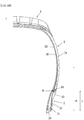
- FIG. 1 is a cross-sectional view showing the configuration of a tire according to an embodiment of the present invention. and more specifically, a cross-sectional view of a tire of size 235 / 75R15.
- the electronic component 34 in the tire axial direction and having a largest thickness in the tire axial direction is the sidewall 31
- the electronic component is provided at the position A as shown in FIG. 1A .
- the rubber member disposed outer side of the electronic component 34 in the tire axial direction and having a largest thickness in the tire axial direction is the clinch 23
- the electronic component is provided at the position B as shown in FIG 1B .
- 1 is a tire
- 2 is a bead portion
- 3 is a sidewall portion
- 4 is a tread
- 21 is a bead core
- 22 is a bead apex
- 23 is a clinch member (hereinafter also referred to as "clinch").
- the clinch is an external member located inside a sidewall in a tire radial direction, and located outer side of a bead apex in a tire axial direction.
- 24 is a chafer
- 31 is a sidewall
- 32 is a carcass ply (hereinafter also referred to as "carcass")
- 33 is an inner liner
- 34 is an electronic component.
- H is the distance from the position of the maximum tire width to the bottom of the bead core
- L is the distance from the bottom of the bead core of the electronic component 34.
- the sidewall 31 will be described as an example of a rubber member disposed outer side of the electronic component in the tire axial direction and having a largest thickness in the tire axial direction.
- the clinch 23 can be considered similarly.
- the sidewall 31 contains 20 parts by mass or more of silica with respect to 100 parts by mass of the rubber component.
- the sidewall portion 3 is configured by sequentially stacking the sidewall 31, the carcass 32, and the inner liner 33 from the outer side in the tire axial direction.
- the electronic component 34 is provided and disposed between the carcass 32 and the sidewall 31.
- the rubber composition used for producing the sidewall 31 can be obtained by kneading a rubber component as a main component and various compounding materials such as a reinforcing material, an anti-aging agent and an additive, using a rubber kneading apparatus such as an open roll, a banbury mixer or the like.
- diene rubbers such as natural rubber (NR), isoprene rubber (IR), butadiene rubber (BR), styrene butadiene rubber (SBR), acrylonitrile butadiene rubber (NBR), chloroprene rubber (CR), butyl rubber (IIR), and the like can be mentioned.
- NR natural rubber
- IR isoprene rubber
- BR butadiene rubber
- SBR styrene butadiene rubber
- NBR acrylonitrile butadiene rubber
- CR chloroprene rubber
- IIR butyl rubber
- the content is preferably 30 parts by mass or more, and more preferably 40 parts by mass or more in 100 parts by mass of the rubber component. Moreover, it is preferably 60 parts by mass or less, and more preferably 50 parts by mass or less.
- the content is preferably 40 parts by mass or more, and more preferably 50 parts by mass or more in 100 parts by mass of the rubber component. Moreover, it is preferably 70 parts by mass or less, and more preferably 60 parts by mass or less.
- the BR is not particularly limited.
- BR having a high cis content BR having a high cis content, BR containing syndiotactic polybutadiene crystals (SPB-containing BR), modified BR, and the like can be used.
- SPB-containing BR is preferable from the viewpoint that extrusion processability can be greatly improved by the intrinsic orientation crystal component.
- the total content of isoprene rubber (NR or IR) and BR is preferably 80 parts by mass or more, and more preferably 90 parts by mass or more, in 100 parts by mass of the rubber component.
- silica is further contained as a reinforcing material.
- silica since silica has no conductivity, when it is used as a reinforcing material, the dielectric constant can be lowered and the read range of the electronic component can be expanded.
- hydration water contained in silica and surface functional groups can capture ozone, ozone resistance can be improved, and durability of tire can be improved.
- the type of silica is not particularly limited.
- wet silica hydrosilicic acid
- dry silica anhydrous silicic acid
- colloidal silica colloidal silica and the like used in commercially available rubber compositions
- Wet silica containing hydration water and containing a large amount of silanol groups is preferable because it can capture ozone effectively.
- the content of silica is preferably 20 parts by mass or more, more preferably 30 parts by mass or more, further preferably 40 parts by mass or more with respect to 100 parts by mass of the rubber component, in order to exert the above-described effects sufficiently and exhibit sufficient reinforcement.
- the upper limit is preferably about 60 parts by mass.
- silane coupling agent in order to improve the dispersibility of the silica as well as to improve the mechanical properties and the moldability by reaction with the silica, it is preferable to additionally contain a silane coupling agent.
- the silane coupling agent is not specifically limited, examples thereof include a sulfide type, a vinyl type, an amino type, a glycidoxy type, a nitro type and a chloro type silane coupling agent. Among them, a sulfide type silane coupling agent is preferable, and bis (3-triethoxysilylpropyl) tetrasulfide is more preferable, from the viewpoint of excellent dispersibility and low heat generation.
- CB carbon black
- a small amount, specifically 10 parts by mass or less, of carbon black (CB) may be used in combination to the above-described silica, as the reinforcing material.
- CB use a low conductivity FEF or the like is preferable in order to suppress an increase in the dielectric constant of the rubber composition.
- Sulfur is used as a vulcanizing agent, and its content is preferably 1 part by mass or more, and more preferably 2 parts by mass or more with respect to 100 parts by mass of the rubber component. Moreover, it is preferably 8 parts by mass or less, and more preferably 6 mass parts or less.
- content of sulfur is pure sulfur content, and when using insoluble sulfur, it is content except oil content.
- Sulfur is usually used together with a vulcanization accelerator.
- Content of the vulcanization accelerator is preferably 0.5 part by mass or more, and more preferably 1.0 part by mass or more with respect to 100 parts by mass of the rubber component. Moreover, it is preferably 5.0 parts by mass or less, and more preferably 4.0 parts by mass or less.
- vulcanization accelerators include sulfenamide type, thiazole type, thiuram type, thiourea type, guanidine type, dithiocarbamic acid type, aldehyde-amine type, aldehyde-ammonia type, imidazoline type and xanthate type vulcanization accelerators. These vulcanization accelerators may be used alone or in combination of two or more. Among these, sulfenamide-type vulcanization accelerators are preferred because the scorch time and the vulcanization time can be balanced.
- a vulcanization accelerator of a basic substance such as guanidine type or the like is used as the vulcanization accelerator, an effect of promoting the reaction between the above-described silica and a silane coupling agent can be exhibited.
- guanidine type examples include 1,3-diphenylguanidine (DPG), 1,3-di-o-tolyl guanidine, 1-o-tolylbiguanide, di-o-tolyl guanidine salt of dicatechol borate, 1,3-di-o-cumenyl guanidine, 1,3-di-o-biphenyl guanidine, 1,3-di-o-cumenyl-2-propionyl guanidine and the like.
- DPG 1,3-diphenylguanidine
- 1,3-di-o-tolyl guanidine 1-o-tolylbiguanide
- di-o-tolyl guanidine salt of dicatechol borate 1,3-di-o-cumenyl guanidine
- 1,3-di-o-biphenyl guanidine 1,3-di-o-cumenyl-2-propionyl guanidine and the like.
- 1,3-diphenylguanidine, 1,3-di-o-tolyl guanidine and 1-o-tolylbiguanide are preferable, and 1,3-diphenylguanidine is more preferable, because of their high reactivity and particularly large effect of promoting the reaction between the silane coupling agent and silica.
- stearic acid conventionally known products can be used. For example, products produced by NOF Corporation, Kao Corporation, Wako Pure Chemical Industries, Ltd., Chiba Fatty Acid Corporation, etc. can be used.
- content of stearic acid is preferably 0.5 part by mass or more, and more preferably 1 part by mass or more, with respect to 100 parts by mass of the rubber component. Moreover, it is preferably 10 parts by mass or less, and more preferably 5 parts by mass or less.
- zinc oxide conventionally known ones can be used. For example, products produced by Mitsui Mining & Smelting Co., Ltd., Toho Zinc Co., Ltd., Hax I Tech Co., Ltd., Shodo Chemical Industry Co., Ltd., etc. can be used.
- content of zinc oxide is preferably 0.5 part by mass or more, and more preferably 1 part by mass or more with respect to 100 parts by mass of the rubber component. Moreover, it is preferably 10 parts by mass or less, and more preferably 5 parts by mass or less.
- an amine-type anti-aging agent having an excellent ozone resistance effect is preferable.
- the amine-type anti-aging agent is not particularly limited, and examples thereof include amine derivatives such as diphenylamine-type, p-phenylenediamine-type, naphthylamine-type and ketone amine condensate-type ones. These may be used alone, and two or more may be used in combination.
- Examples of diphenylamine type derivatives include p-(p-toluenesulfonylamide) -diphenylamine, octylated diphenylamine, 4,4'-bis ( ⁇ , ⁇ '-dimethylbenzyl) diphenylamine and the like.
- Examples of p-phenylenediamine type derivatives include N-(1,3-dimethylbutyl)-N'-phenyl-p-phenylenediamine (6PPD), N-phenyl-N'-isopropyl-p-phenylenediamine (IPPD) and N, N'-di-2-naphthyl-p-phenylenediamine.
- Examples of the naphthylamine type derivatives include phenyl- ⁇ -naphthylamine and the like. Among them, phenylenediamine type and ketone amine condensate type are preferable.
- Content of the anti-aging agent is preferably 0.3 part by mass or more, and more preferably 0.5 part by mass or more with respect to 100 parts by mass of the rubber component. Moreover, it is preferably 8 parts by mass or less, and more preferably 2.5 parts by mass or less.
- Waxes are not particularly limited, and petroleum waxes such as paraffin wax and microcrystalline wax; natural waxes such as plant wax and animal waxes; synthetic waxes such as polymers of ethylene and propylene etc. can be mentioned as the examples. These may be used alone or in combination of two or more.
- wax products manufactured by Ouchi Shinko Chemical Co., Ltd., Nippon Seiro Co., Ltd., Seiko Kagaku Co., Ltd., etc. can be used.
- content of the wax is preferably 0.5 part by mass or more, and more preferably 1 part by mass or more with respect to 100 parts by mass of the rubber component. Moreover, it is preferably 10 parts by mass or less, and more preferably 7 parts by mass or less.
- oils examples include process oils, vegetable oils and fats, and mixtures thereof.
- process oil for example, paraffin-based process oil, aroma-based process oil, naphthene-based process oil and the like can be used.
- vegetable fats and oils include castor oil, cottonseed oil, linseed oil, rapeseed oil, soybean oil, palm oil, peanut oil, rosin, pine oil, pine tar, tall oil, corn oil, rice oil, beni flower oil, sesame oil, olive oil, sunflower oil, palm kernel oil, camellia oil, jojoba oil, macadamia nut oil, tung oil and the like. These may be used alone or in combination of two or more.
- the content of oil is preferably 0.5 part by mass or more, and more preferably 1 part by mass or more with respect to 100 parts by mass of the rubber component. Moreover, it is preferably 10 parts by mass or less, and more preferably 5 parts by mass or less.
- the rubber composition according to the present embodiment may be compounded materials conventionally used in the rubber industry.
- an inorganic filler such as talc or calcium carbonate
- an organic filler such as cellulose fiber
- a softener such as liquid rubber or adhesive resin
- a vulcanizing agent other than sulfur such as sulfur, an organic crosslinking agent, or the like
- the compounding quantity of each compounding material can be selected suitably.
- the tire according to the present embodiment has the electronic component embedded therein.
- the electronic components include RFID, pressure sensor, temperature sensor, acceleration sensor, magnetic sensor, groove depth sensor, and the like.
- RFID is particularly preferable because it can store and read a large volume of non-contact information, so it can store tire manufacturing information, management information, customer information, etc. in addition to data such as pressure and temperature.
- the electronic component 34 is disposed between the bead apex and the sidewall (or clinch), and outer side of the bead apex in the tire axial direction. It is provided in close proximity to the carcass 32 between the bead reinforcing layer, which suppresses the deformation of the bead apex, and the sidewall (or clinch). As a result, it is possible to suppress the occurrence of local stress concentration and becoming a fracture start point of the carcass. Specific embedding position is not particularly limited as far as reliable information communication is possible and the electronic component is not easily damaged by the deformation of the tire.
- the height from the bottom of the bead core (L in FIG. 1 ) is 20 to 80% with respect to the distance from the position of the maximum tire width to the bottom of the bead core in the equatorial direction (H in FIG. 1 ), as the position where the damage of the electronic component by the deformation of the tire is relatively small, and communication can be made without problems from the outside when assembled in the rim.
- the size (long length including the IC chip and the antenna) of the electronic component to be embedded in the present embodiment is preferably 18 cm or less, more preferably 9 cm or less, further preferably 4 cm or less, and most preferably 2 cm or less. With such a small size, stress may be concentrated on the surrounding rubber, but, since consideration is given to local stress concentration as described above, the durability of the tire can be stably maintained, in the present embodiment. At this time, bending of the antenna portion can be kept to a minimum by arranging the antenna portion of the electronic component to extend in a direction orthogonal to the cord of the carcass.
- the antenna of the RFID is preferably formed of conductive rubber. Since the conductive rubber is flexible, there is no risk of impairing the sidewall or clinch function even if the antenna is enlarged to improve the communication function.
- the tire of the present embodiment can be manufactured by a usual method except for disposing the electronic component during molding. That is, the sidewall 31 (or clinch 23) is formed by extrusion processing according to the shape of the sidewall (or clinch) at the unvulcanized stage of the rubber composition, then it is pasted together with other tire members to form an unvulcanized tire by a usual method on a tire molding machine.
- the electronic component is embedded at a predetermined position during the molding.
- the unvulcanized tire in which the electronic component is disposed is heated and pressurized in a vulcanizer to manufacture a tire.
- Table 1 shows the compounding materials.
- Table 2 shows the formulation.
- [Table 1] Compounding materials Product Name Manufacturer (Rubber component) NR TSR20 BR UBEPOL BR 150B Ube Industries, Ltd. (Reinforcing material) Silica ULTRASIL VN3 Evonik Carbon Black 1 SHOWBLACK N550 Cabot Japan Carbon Black 2 LIONITE Lion Specialty Chemicals Co., Ltd. (Silane coupling agent) Si266 Si266 Evonik (Softener) Oil Diana Process AH-24 Idemitsu Kosan Co., Ltd. (Anti-aging agent) Anti-aging agent NOCLAC 6C Ouchi Shinko Chemical Co., Ltd.
- a rubber composition for coating electronic component 34 can be obtained.
- the obtained unvulcanized rubber composition is molded into a sidewall (or clinch) shape, and is laminated and pasted together with other tire members on a tire forming machine.
- the electronic component 34 coated by the unvulcanized rubber composition is provided at a position A shown in FIG. 1A described later, specifically at a position 80% from the bottom of the bead core, in the case of sidewall, or at a position B shown in FIG. 1B , specifically at a position 45% from the bottom of the bead core, in the case of clinch, followed by conducting vulcanization at 150 °C for 30 minutes to obtain a test tire (tire size: 205/65 R16).
- the above values for position are values with respect to the distance from the position of the maximum tire width to the bottom of the bead core.
- an RFID in which a 30 mm antenna is provided on both sides of a 3 mm ⁇ 3 mm ⁇ 0.4 mm IC chip can be used.
- Tables 4 to 6 show the relationship between the formulation of the sidewall (or clinch), the durability of the tire, and the communication performance of the electronic component.
- the evaluation of the durability of the above tire is "Y"(acceptable) if it is possible to drive 10,000 km on a general road after exposing the tire to ozone under the conditions shown in Table 3, and "NG"(not acceptable) if it is not possible.
- the mounting rim is 16 ⁇ 6.0
- the tire internal pressure is 230 kPa
- the test vehicle is a front wheel drive vehicle
- the displacement is 2000 cc
- the tire mounting position is all wheels.
- the evaluation method of communication property is a method where transceivers for the electronic component are installed at three measurement points (a to c) of the circle shown in FIG. 3 and it is judged whether communication of data with the electronic component is possible.
- the tire is assembled in a rim and mounted in a vehicle for conducting the measurement, and the ratio of (the number of readable positions after the durability evaluation / the number of readable positions before the durability evaluation) is calculated.
- the evaluation result is "EX"(excellent), if the average value of the four tire is 60% or more; “G”(good), if 50% or more and less than 60%; “Y”(acceptable), if more than 0% and less than 50%; and "NG”(not acceptable), if 0% or readable position before durability evaluation is 0.
- Example 3 Formulation of sidewall 1 2 3 4 5 6 7 Formulation of clinch 1 1 1 1 1 1 1 Position of RFID A A A A A A A Durability of tire Y Y Y Y Y NG NG Communication performance of electronic component EX EX G G NG - - [Table 5] Examples/ Comparative examples Example 5 Example 6 Example 7 Example 8 Compar. Example 4 ompar. Example 5 Compar.
- Example 6 Formulation of sidewall 1 1 1 1 1 1 1 Formulation of clinch 1 2 3 4 5 6 7 Position of RFID B B B B B B Durability of tire Y Y Y Y Y NG NG Communication performance of electronic component EX EX EX EX NG - - [Table 6] Examples/ Comparative examples Example 9 Example 10 Example 11 Compar. Example 8 Compar. Example 9 Compar. Example 10 Formulation of sidewall 2 3 4 6 4 6 Formulation of clinch 1 2 5 5 5 5 Position of RFID B B A A B B Durability of tire Y Y Y NG NG NG NG NG NG NG NG NG NG NG NG NG NG NG NG NG NG NG NG NG NG NG NG NG NG NG NG NG NG NG NG NG NG NG NG NG NG NG NG NG NG NG NG NG NG NG NG NG NG NG NG NG NG NG Communication performance
Landscapes
- Chemical & Material Sciences (AREA)
- Health & Medical Sciences (AREA)
- Chemical Kinetics & Catalysis (AREA)
- Medicinal Chemistry (AREA)
- Polymers & Plastics (AREA)
- Organic Chemistry (AREA)
- Engineering & Computer Science (AREA)
- Mechanical Engineering (AREA)
- Tires In General (AREA)
Abstract
Description
- The present invention relates to a pneumatic tire in which an electronic component such as RFID is provided.
- In recent years, in order to monitor various data such as the internal pressure, temperature and rotational speed of pneumatic tires (hereinafter, also simply referred to as "tires") to improve safety, maintainability, etc. while the vehicle is traveling, it has been proposed that an electronic component such as a transponder for RFID (Radio Frequency Identification) (hereinafter, also simply referred to as "RFID") for recording the data is to be provided to a tire.
- The transponder is a small, lightweight electronic component consisting of a semiconductor chip with a transmitter/receiver circuit, a control circuit, a memory, etc., and an antenna. As the transponder, Battery-less one is often used which can transmit various data as response radio waves when it receives an inquiry radio wave, which is used as electrical energy.
- As a method of providing such an electronic component to a tire, a method has been proposed in which the electronic component is adhered to the surface of the tire after vulcanization by adhesion or the like (for example, Patent Document 1). However, when this method is adopted, there is a problem that the electronic component easily falls-off while traveling on the road surface, although there is little risk that the electronic component will be destroyed.
- Then, in order to prevent falling-off of electronic component, a method has been proposed in which the electronic component is integrated with a tire by vulcanization adhesion accompanying vulcanization molding after molding the green tire while embedding the electronic component inside (for example, Patent Document 2).
-
- [Patent document 1]
JP2006-168473 A - [Patent document 2]
JP2008-265750 A - However, when a method of integrating an electronic component and an unvulcanized tire by providing the electronic component into the tire is adopted, it is difficult to obtain sufficient reading performance and there is a problem that the durability of the tire decreases, although there is no risk of the electronic component falling-off.
- Therefore, an object of the present invention to provide a manufacturing technology for a tire capable of securing sufficient reading performance and preventing decrease in tire durability, even if the tire has an electronic component provided therein.
- The inventors of the present invention have earnestly studied for solving the problem, found that the problem can be solved by the invention described below, and completed the present invention.
- The invention according to
claim 1 is;
a pneumatic tire which has an electronic component provided therein,
wherein the electronic component is provided outer side of the carcass in the tire axial direction, and
the rubber member having the largest thickness in the tire axial direction among the rubber members disposed outer side of the electronic component in the tire axial direction contains 20 parts by mass or more of silica with respect to 100 parts by mass of the rubber component. - The invention according to
claim 2 is;
the pneumatic tire according toclaim 1 wherein
the content of silica of the rubber member having the largest thickness in the tire axial direction is 30 parts by mass or more with respect to 100 parts by mass of the rubber component. - The invention according to
claim 3 is;
the pneumatic tire according toclaim 2 wherein
the content of silica of the rubber member having the largest thickness in the tire axial direction is 40 parts by mass or more with respect to 100 parts by mass of the rubber component. - The invention according to
claim 4 is;
the pneumatic tire according to any one ofclaims 1 to 3, wherein
the rubber member having the largest thickness in the tire axial direction is a sidewall. - The invention according to claim 5 is;
the pneumatic tire according to any one ofclaims 1 to 3, wherein
the rubber member having the largest thickness in the tire axial direction is a clinch. - The invention according to claim 6 is;
the pneumatic tire according to any one ofclaims 1 to 5, wherein
the electronic component is located outer side of the carcass in the tire axial direction in the cross-sectional view, and is embedded at a position of 20 to 80% from the bottom of bead core with respect to the distance from the position of the maximum tire width to the bottom of bead core in the equatorial direction. - According to the present invention, a manufacturing technology for tire is provided which secures sufficient reading performance of the tire and does not decrease durability of the tire, even when the tire has an electronic component provided therein.
-
- [
Figure 1A ] This figure is a cross-sectional view showing a configuration of a pneumatic tire according to an embodiment of the present invention. - [
Figure 1B ] This figure is a cross-sectional view showing a configuration of a pneumatic tire according to another embodiment of the present invention. - [
Figure 2 ] It is a figure explaining the communication measurement points in the Example of this invention. - Hereinafter, the present invention will be described based on embodiments.
- In a tire provided with an electronic component, it is preferable to dispose the electronic component outer side of the carcass in the tire axial direction, for example, inside of a layer such as a sidewall or a clinch, in consideration of transmission and reception of data with the electronic component.
- However, in the case of the conventional tire, as described above, there is a problem that it is difficult to obtain sufficient reading performance and the durability of the tire decreases.
- The inventors of the present invention have considered that the cause of the difficulty in obtaining sufficient reading performance is that carbon is compounded in tire members such as sidewalls and clinch. That is, when carbon is compounded, it was considered that the reading range of the electronic component becomes narrower because the dielectric constant is increased. In addition, when the ozone resistance of these members is low, ozone deterioration occurs to cause surface cracks, and the cracks progress to reach the electronic component provided inside, thereby causing damage to the tire.
- Therefore, the inventors of the present invention have considered that silica having no conductivity is compounded as a material for lowering the dielectric constant, in these members. Then, experiments and studies were conducted and it was confirmed that the sufficient reading performance and the durability of the tire can be obtained by compounding silica. Although the details of the mechanism by which such an effect was obtained are unknown, it is guessed as follows.
- That is, since the silica does not have conductivity, the rubber composition containing the silica has a reduced dielectric constant. As a result, the reading range of the electronic component is expanded. In addition, since silica has a function of capturing ozone by its hydration water or its functional group on the surface, the rubber composition containing silica improves the ozone resistance and leads to the improvement in the durability of the tire.
- It is not necessary to compound silica to all the members for expressing this effect, and it was found to be sufficient that the rubber member having the largest thickness in the tire axial direction, among the rubber members disposed outer side of the electronic component in the tire axial direction, specifically sidewall, clinch, etc., contains 20 parts by mass or more of silica with respect to 100 parts by mass of the rubber component. Thus, the present invention was completed.
- As described above, in the tire according to the present embodiment, an electronic component is provided inside, and the rubber member having the largest thickness in the tire axis direction among the rubber members disposed outside of the electronic component in the tire axial direction contains 20 parts by mass or more of silica with respect to 100 parts by mass of the rubber component.
- The tire according to the present embodiment will be described with reference to
FIG. 1. FIG. 1 is a cross-sectional view showing the configuration of a tire according to an embodiment of the present invention. and more specifically, a cross-sectional view of a tire of size 235 / 75R15. - In the case where the rubber member disposed outer side of the
electronic component 34 in the tire axial direction and having a largest thickness in the tire axial direction is thesidewall 31, the electronic component is provided at the position A as shown inFIG. 1A . On the other hand, when the rubber member disposed outer side of theelectronic component 34 in the tire axial direction and having a largest thickness in the tire axial direction is theclinch 23, the electronic component is provided at the position B as shown inFIG 1B . - In
FIG. 1, 1 is a tire, 2 is a bead portion, 3 is a sidewall portion, 4 is a tread, 21 is a bead core, 22 is a bead apex, and 23 is a clinch member (hereinafter also referred to as "clinch"). In this case, the clinch is an external member located inside a sidewall in a tire radial direction, and located outer side of a bead apex in a tire axial direction. Further, 24 is a chafer, 31 is a sidewall, 32 is a carcass ply (hereinafter also referred to as "carcass"), 33 is an inner liner, and 34 is an electronic component. In this case, inFIG. 1 , H is the distance from the position of the maximum tire width to the bottom of the bead core, and L is the distance from the bottom of the bead core of theelectronic component 34. - Hereinafter, the
sidewall 31 will be described as an example of a rubber member disposed outer side of the electronic component in the tire axial direction and having a largest thickness in the tire axial direction. However, theclinch 23 can be considered similarly. - In this embodiment, the
sidewall 31 contains 20 parts by mass or more of silica with respect to 100 parts by mass of the rubber component. - In the present embodiment, the
sidewall portion 3 is configured by sequentially stacking thesidewall 31, thecarcass 32, and theinner liner 33 from the outer side in the tire axial direction. Theelectronic component 34 is provided and disposed between thecarcass 32 and thesidewall 31. - In the present embodiment, the rubber composition used for producing the
sidewall 31 can be obtained by kneading a rubber component as a main component and various compounding materials such as a reinforcing material, an anti-aging agent and an additive, using a rubber kneading apparatus such as an open roll, a banbury mixer or the like. - As a rubber component, diene rubbers such as natural rubber (NR), isoprene rubber (IR), butadiene rubber (BR), styrene butadiene rubber (SBR), acrylonitrile butadiene rubber (NBR), chloroprene rubber (CR), butyl rubber (IIR), and the like can be mentioned. Combined use of isoprene rubber (NR or IR) and BR is preferable because low fuel consumption and durability can be favorably obtained.
- In the isoprene-type rubber (NR or IR), the content is preferably 30 parts by mass or more, and more preferably 40 parts by mass or more in 100 parts by mass of the rubber component. Moreover, it is preferably 60 parts by mass or less, and more preferably 50 parts by mass or less. By setting the content of isoprene-type rubber (NR or IR) in the rubber component in the above range, sufficient breaking elongation and sufficient resistance to bending crack growth can be secured.
- In BR, the content is preferably 40 parts by mass or more, and more preferably 50 parts by mass or more in 100 parts by mass of the rubber component. Moreover, it is preferably 70 parts by mass or less, and more preferably 60 parts by mass or less. By setting the content of BR in the rubber component within the above range, sufficient resistance to bending crack growth and sufficient breaking strength can be secured.
- In this case, the BR is not particularly limited. For example, BR having a high cis content, BR containing syndiotactic polybutadiene crystals (SPB-containing BR), modified BR, and the like can be used. Among them, SPB-containing BR is preferable from the viewpoint that extrusion processability can be greatly improved by the intrinsic orientation crystal component.
- In the combined use of isoprene rubber (NR or IR) and BR, the total content of isoprene rubber (NR or IR) and BR is preferably 80 parts by mass or more, and more preferably 90 parts by mass or more, in 100 parts by mass of the rubber component. By setting the total content of isoprene-based rubber (NR and IR) and BR within the above range, sufficient low fuel consumption and sufficient durability can be secured.
- In the present embodiment, silica is further contained as a reinforcing material. As described above, since silica has no conductivity, when it is used as a reinforcing material, the dielectric constant can be lowered and the read range of the electronic component can be expanded. In addition, since hydration water contained in silica and surface functional groups can capture ozone, ozone resistance can be improved, and durability of tire can be improved.
- In the present embodiment, the type of silica is not particularly limited. For example, wet silica (hydrous silicic acid), dry silica (anhydrous silicic acid), colloidal silica and the like used in commercially available rubber compositions can be used. Wet silica containing hydration water and containing a large amount of silanol groups is preferable because it can capture ozone effectively.
- The content of silica is preferably 20 parts by mass or more, more preferably 30 parts by mass or more, further preferably 40 parts by mass or more with respect to 100 parts by mass of the rubber component, in order to exert the above-described effects sufficiently and exhibit sufficient reinforcement. Considering processability of the rubber composition or the like, the upper limit is preferably about 60 parts by mass.
- At this time, in order to improve the dispersibility of the silica as well as to improve the mechanical properties and the moldability by reaction with the silica, it is preferable to additionally contain a silane coupling agent.
- Although the silane coupling agent is not specifically limited, examples thereof include a sulfide type, a vinyl type, an amino type, a glycidoxy type, a nitro type and a chloro type silane coupling agent. Among them, a sulfide type silane coupling agent is preferable, and bis (3-triethoxysilylpropyl) tetrasulfide is more preferable, from the viewpoint of excellent dispersibility and low heat generation.
- In addition, a small amount, specifically 10 parts by mass or less, of carbon black (CB) may be used in combination to the above-described silica, as the reinforcing material. At this time, as the CB, use a low conductivity FEF or the like is preferable in order to suppress an increase in the dielectric constant of the rubber composition.
- Sulfur is used as a vulcanizing agent, and its content is preferably 1 part by mass or more, and more preferably 2 parts by mass or more with respect to 100 parts by mass of the rubber component. Moreover, it is preferably 8 parts by mass or less, and more preferably 6 mass parts or less. By setting the content of sulfur within the above range, sufficient steering stability can be secured, the bloom and adhesion of sulfur can be suppressed, and the durability can be secured. In this case, content of sulfur is pure sulfur content, and when using insoluble sulfur, it is content except oil content.
- Sulfur is usually used together with a vulcanization accelerator. Content of the vulcanization accelerator is preferably 0.5 part by mass or more, and more preferably 1.0 part by mass or more with respect to 100 parts by mass of the rubber component. Moreover, it is preferably 5.0 parts by mass or less, and more preferably 4.0 parts by mass or less. By setting the content of the vulcanization accelerator within the above range, the effects of the present invention tend to be favorably obtained. Specific examples of the vulcanization accelerators include sulfenamide type, thiazole type, thiuram type, thiourea type, guanidine type, dithiocarbamic acid type, aldehyde-amine type, aldehyde-ammonia type, imidazoline type and xanthate type vulcanization accelerators. These vulcanization accelerators may be used alone or in combination of two or more. Among these, sulfenamide-type vulcanization accelerators are preferred because the scorch time and the vulcanization time can be balanced.
- When a vulcanization accelerator of a basic substance such as guanidine type or the like is used as the vulcanization accelerator, an effect of promoting the reaction between the above-described silica and a silane coupling agent can be exhibited.
- Specific examples of guanidine type include 1,3-diphenylguanidine (DPG), 1,3-di-o-tolyl guanidine, 1-o-tolylbiguanide, di-o-tolyl guanidine salt of dicatechol borate, 1,3-di-o-cumenyl guanidine, 1,3-di-o-biphenyl guanidine, 1,3-di-o-cumenyl-2-propionyl guanidine and the like. Among them, 1,3-diphenylguanidine, 1,3-di-o-tolyl guanidine and 1-o-tolylbiguanide are preferable, and 1,3-diphenylguanidine is more preferable, because of their high reactivity and particularly large effect of promoting the reaction between the silane coupling agent and silica.
- As stearic acid, conventionally known products can be used. For example, products produced by NOF Corporation, Kao Corporation, Wako Pure Chemical Industries, Ltd., Chiba Fatty Acid Corporation, etc. can be used. When stearic acid is used, content of stearic acid is preferably 0.5 part by mass or more, and more preferably 1 part by mass or more, with respect to 100 parts by mass of the rubber component. Moreover, it is preferably 10 parts by mass or less, and more preferably 5 parts by mass or less. By setting the content of stearic acid within the above range, the effects of the present invention tend to be obtained well.
- As zinc oxide, conventionally known ones can be used. For example, products produced by Mitsui Mining & Smelting Co., Ltd., Toho Zinc Co., Ltd., Hax I Tech Co., Ltd., Shodo Chemical Industry Co., Ltd., etc. can be used. When using zinc oxide, content of zinc oxide is preferably 0.5 part by mass or more, and more preferably 1 part by mass or more with respect to 100 parts by mass of the rubber component. Moreover, it is preferably 10 parts by mass or less, and more preferably 5 parts by mass or less. By setting the content of zinc oxide within the above range, the effects of the present invention tend to be obtained better.
- As the anti-aging agent, an amine-type anti-aging agent having an excellent ozone resistance effect is preferable. The amine-type anti-aging agent is not particularly limited, and examples thereof include amine derivatives such as diphenylamine-type, p-phenylenediamine-type, naphthylamine-type and ketone amine condensate-type ones. These may be used alone, and two or more may be used in combination. Examples of diphenylamine type derivatives include p-(p-toluenesulfonylamide) -diphenylamine, octylated diphenylamine, 4,4'-bis (α, α'-dimethylbenzyl) diphenylamine and the like. Examples of p-phenylenediamine type derivatives include N-(1,3-dimethylbutyl)-N'-phenyl-p-phenylenediamine (6PPD), N-phenyl-N'-isopropyl-p-phenylenediamine (IPPD) and N, N'-di-2-naphthyl-p-phenylenediamine. Examples of the naphthylamine type derivatives include phenyl-α-naphthylamine and the like. Among them, phenylenediamine type and ketone amine condensate type are preferable. Content of the anti-aging agent is preferably 0.3 part by mass or more, and more preferably 0.5 part by mass or more with respect to 100 parts by mass of the rubber component. Moreover, it is preferably 8 parts by mass or less, and more preferably 2.5 parts by mass or less.
- Waxes are not particularly limited, and petroleum waxes such as paraffin wax and microcrystalline wax; natural waxes such as plant wax and animal waxes; synthetic waxes such as polymers of ethylene and propylene etc. can be mentioned as the examples. These may be used alone or in combination of two or more. As specific examples of wax, products manufactured by Ouchi Shinko Chemical Co., Ltd., Nippon Seiro Co., Ltd., Seiko Kagaku Co., Ltd., etc. can be used. When a wax is used, content of the wax is preferably 0.5 part by mass or more, and more preferably 1 part by mass or more with respect to 100 parts by mass of the rubber component. Moreover, it is preferably 10 parts by mass or less, and more preferably 7 parts by mass or less.
- Examples of oils include process oils, vegetable oils and fats, and mixtures thereof. As the process oil, for example, paraffin-based process oil, aroma-based process oil, naphthene-based process oil and the like can be used. Examples of vegetable fats and oils include castor oil, cottonseed oil, linseed oil, rapeseed oil, soybean oil, palm oil, peanut oil, rosin, pine oil, pine tar, tall oil, corn oil, rice oil, beni flower oil, sesame oil, olive oil, sunflower oil, palm kernel oil, camellia oil, jojoba oil, macadamia nut oil, tung oil and the like. These may be used alone or in combination of two or more. Specific examples of the oil which can be used include products manufactured by Idemitsu Kosan Co., Ltd., Sankyo Yuka Kogyo Co., Ltd., Japan Energy Co., Ltd., Orisoi Company, H & R Company, Toyokuni Oil Co., Ltd., Showa Shell Co., Ltd., Fuji Kosan Co., Ltd., etc. The content of oil is preferably 0.5 part by mass or more, and more preferably 1 part by mass or more with respect to 100 parts by mass of the rubber component. Moreover, it is preferably 10 parts by mass or less, and more preferably 5 parts by mass or less.
- In addition to the above components, the rubber composition according to the present embodiment may be compounded materials conventionally used in the rubber industry. For example, an inorganic filler such as talc or calcium carbonate, an organic filler such as cellulose fiber, a softener such as liquid rubber or adhesive resin, a vulcanizing agent other than sulfur, an organic crosslinking agent, or the like may be compounded as required. The compounding quantity of each compounding material can be selected suitably.
- The tire according to the present embodiment has the electronic component embedded therein. Specific examples of the electronic components include RFID, pressure sensor, temperature sensor, acceleration sensor, magnetic sensor, groove depth sensor, and the like. Above all, RFID is particularly preferable because it can store and read a large volume of non-contact information, so it can store tire manufacturing information, management information, customer information, etc. in addition to data such as pressure and temperature.
- In the present embodiment, the
electronic component 34 is disposed between the bead apex and the sidewall (or clinch), and outer side of the bead apex in the tire axial direction. It is provided in close proximity to thecarcass 32 between the bead reinforcing layer, which suppresses the deformation of the bead apex, and the sidewall (or clinch). As a result, it is possible to suppress the occurrence of local stress concentration and becoming a fracture start point of the carcass. Specific embedding position is not particularly limited as far as reliable information communication is possible and the electronic component is not easily damaged by the deformation of the tire. However, it is preferable to be disposed at a position outer side of the carcass end in the tire axial direction in the cross-sectional view of tire, where the height from the bottom of the bead core (L inFIG. 1 ) is 20 to 80% with respect to the distance from the position of the maximum tire width to the bottom of the bead core in the equatorial direction (H inFIG. 1 ), as the position where the damage of the electronic component by the deformation of the tire is relatively small, and communication can be made without problems from the outside when assembled in the rim. - The size (long length including the IC chip and the antenna) of the electronic component to be embedded in the present embodiment is preferably 18 cm or less, more preferably 9 cm or less, further preferably 4 cm or less, and most preferably 2 cm or less. With such a small size, stress may be concentrated on the surrounding rubber, but, since consideration is given to local stress concentration as described above, the durability of the tire can be stably maintained, in the present embodiment. At this time, bending of the antenna portion can be kept to a minimum by arranging the antenna portion of the electronic component to extend in a direction orthogonal to the cord of the carcass.
- In addition, the antenna of the RFID is preferably formed of conductive rubber. Since the conductive rubber is flexible, there is no risk of impairing the sidewall or clinch function even if the antenna is enlarged to improve the communication function.
- The tire of the present embodiment can be manufactured by a usual method except for disposing the electronic component during molding. That is, the sidewall 31 (or clinch 23) is formed by extrusion processing according to the shape of the sidewall (or clinch) at the unvulcanized stage of the rubber composition, then it is pasted together with other tire members to form an unvulcanized tire by a usual method on a tire molding machine. The electronic component is embedded at a predetermined position during the molding.
- Thereafter, the unvulcanized tire in which the electronic component is disposed is heated and pressurized in a vulcanizer to manufacture a tire.
- Table 1 shows the compounding materials. Table 2 shows the formulation.
[Table 1] Compounding materials Product Name Manufacturer (Rubber component) NR TSR20 BR UBEPOL BR 150B Ube Industries, Ltd. (Reinforcing material) Silica ULTRASIL VN3 Evonik Carbon Black 1 SHOWBLACK N550 Cabot Japan Carbon Black 2 LIONITE Lion Specialty Chemicals Co., Ltd. (Silane coupling agent) Si266 Si266 Evonik (Softener) Oil Diana Process AH-24 Idemitsu Kosan Co., Ltd. (Anti-aging agent) Anti-aging agent NOCLAC 6C Ouchi Shinko Chemical Co., Ltd. (Vulcanizing agent) Sulfur Insoluble Sulfur Tsurumi Chemical Industry Co., Ltd. Vulcanization Accelerator 1SANCELER NS-G Sanshin Chemical Industry Co., Ltd. Vulcanization Accelerator 2SOXINOL D-G Sumitomo Clemical Co., Ltd. (Others) Stearic acid Camellia oil NOF CORPORATION Zinc oxide Zinc Flower 1 Mitsui Mining & Smelting Co., Ltd. Wax SANNOC N Ouchi Shinko Chemical Co., Ltd. [Table 2] Formulation No. 1 2 3 4 5 6 7 FORMUL ATION NR 50 50 50 50 50 50 50 BR 50 50 50 50 50 50 50 Carbon Black 15 10 10 10 20 - - Carbon Black 2 - - - - - 65 40 Silica 40 40 30 20 10 - - Coupling agent 4 2 2 2 1 - - Oil 5 5 5 5 5 5 5 Wax 1 1 1 1 1 2 2 Anti-aging agent 3 3 3 3 3 3 3 Stearic acid 2 2 2 2 2 2 2 Zinc oxide 3 3 3 3 3 3 3 Sulfur 2.5 2.5 2.5 2.5 2.5 2.5 2.5 Vulcanization accelerator2 1.0 0.5 0.5 0.5 0.5 - - Vulcanization accelerator 13.0 1.0 1.0 1.0 0.8 3.0 1.0 - Based on Table 1 and Table 2, using a banbury mixer manufactured by Kobe Steel, Ltd., compounding materials other than sulfur and a vulcanization accelerator are kneaded, then, to the kneaded product obtained, sulfur and vulcanization acceleration are added and kneaded using an open roll to obtain an unvulcanized rubber composition for sidewall (or clinch).
- Moreover, according to Example 1 of
JP 2013-245339 A electronic component 34 can be obtained. - Then, the obtained unvulcanized rubber composition is molded into a sidewall (or clinch) shape, and is laminated and pasted together with other tire members on a tire forming machine. And, the
electronic component 34 coated by the unvulcanized rubber composition is provided at a position A shown inFIG. 1A described later, specifically at a position 80% from the bottom of the bead core, in the case of sidewall, or at a position B shown inFIG. 1B , specifically at a position 45% from the bottom of the bead core, in the case of clinch, followed by conducting vulcanization at 150 °C for 30 minutes to obtain a test tire (tire size: 205/65 R16). The above values for position are values with respect to the distance from the position of the maximum tire width to the bottom of the bead core. As theelectronic component 34, an RFID in which a 30 mm antenna is provided on both sides of a 3 mm × 3 mm × 0.4 mm IC chip can be used. - Tables 4 to 6 show the relationship between the formulation of the sidewall (or clinch), the durability of the tire, and the communication performance of the electronic component.
- The evaluation of the durability of the above tire is "Y"(acceptable) if it is possible to drive 10,000 km on a general road after exposing the tire to ozone under the conditions shown in Table 3, and "NG"(not acceptable) if it is not possible. As for the driving conditions, the mounting rim is 16 × 6.0, the tire internal pressure is 230 kPa, the test vehicle is a front wheel drive vehicle, the displacement is 2000 cc, and the tire mounting position is all wheels.
[Table 3] Ozone concentration 50pphm Temperature 40 °C Humidity 65%RH Exposing time 168 h - The evaluation method of communication property is a method where transceivers for the electronic component are installed at three measurement points (a to c) of the circle shown in FIG. 3 and it is judged whether communication of data with the electronic component is possible.
- Specifically, the tire is assembled in a rim and mounted in a vehicle for conducting the measurement, and the ratio of (the number of readable positions after the durability evaluation / the number of readable positions before the durability evaluation) is calculated. The evaluation result is "EX"(excellent), if the average value of the four tire is 60% or more; "G"(good), if 50% or more and less than 60%; "Y"(acceptable), if more than 0% and less than 50%; and "NG"(not acceptable), if 0% or readable position before durability evaluation is 0.
[Table 4] Examples/ Comparative examples Example 1 Example 2 Example 3 Example 4 Compar. Example 1 Compar. Example 2 Compar. Example 3 Formulation of sidewall 1 2 3 4 5 6 7 Formulation of clinch 1 1 1 1 1 1 1 Position of RFID A A A A A A A Durability of tire Y Y Y Y Y NG NG Communication performance of electronic component EX EX G G NG - - [Table 5] Examples/ Comparative examples Example 5 Example 6 Example 7 Example 8 Compar. Example 4 ompar. Example 5 Compar. Example 6 Formulation of sidewall 1 1 1 1 1 1 1 Formulation of clinch 1 2 3 4 5 6 7 Position of RFID B B B B B B B Durability of tire Y Y Y Y Y NG NG Communication performance of electronic component EX EX EX EX NG - - [Table 6] Examples/ Comparative examples Example 9 Example 10 Example 11 Compar. Example 8 Compar. Example 9 Compar. Example 10 Formulation of sidewall 2 3 4 6 4 6 Formulation of clinch 1 2 5 5 5 5 Position of RFID B B A A B B Durability of tire Y Y Y NG NG NG Communication performance of electronic component EX EX G - - - - As mentioned above, although the present invention was explained based on an embodiment, the present invention is not limited to the above-mentioned embodiment. Various modifications can be made to the above embodiment within the same and equivalent scope of the present invention.
-
- 1 tire
- 2 bead portion
- 3 sidewall portion
- 4 tread
- 21 bead core
- 22 bead apex
- 23 clinch
- 24 chafer
- 31 sidewall
- 32 carcass ply
- 33 inner liner
- 34 electronic component
- A, B Position of electronic component
- H Distance from the position of maximum tire width to the bottom of bead core
- L Distance from the bottom of bead core of electronic component
Claims (6)
- A pneumatic tire which has an electronic component provided therein,
wherein the electronic component is provided outer side of the carcass in the tire axial direction, and
the rubber member having the largest thickness in the tire axial direction among the rubber members disposed outer side of the electronic component in the tire axial direction contains 20 parts by mass or more of silica with respect to 100 parts by mass of the rubber component. - The pneumatic tire according to claim 1 wherein
the content of silica of the rubber member having the largest thickness in the tire axial direction is 30 parts by mass or more with respect to 100 parts by mass of the rubber component. - The pneumatic tire according to claim 2 wherein
the content of silica of the rubber member having the largest thickness in the tire axial direction is 40 parts by mass or more with respect to 100 parts by mass of the rubber component. - The pneumatic tire according to any one of claims 1 to 3, wherein the rubber member having the largest thickness in the tire axial direction is a sidewall.
- The pneumatic tire according to any one of claims 1 to 3, wherein the rubber member having the largest thickness in the tire axial direction is a clinch.
- The pneumatic tire according to any one of claims 1 to 5, wherein
the electronic component is located outer side of the carcass in the tire axial direction in the cross-sectional view, and is embedded at a position of 20 to 80% from the bottom of bead core with respect to the distance from the position of the maximum tire width to the bottom of bead core in the equatorial direction.
Applications Claiming Priority (2)
| Application Number | Priority Date | Filing Date | Title |
|---|---|---|---|
| JP2017175250 | 2017-09-12 | ||
| PCT/JP2018/032661 WO2019054227A1 (en) | 2017-09-12 | 2018-09-03 | Pneumatic tire |
Publications (3)
| Publication Number | Publication Date |
|---|---|
| EP3677439A1 true EP3677439A1 (en) | 2020-07-08 |
| EP3677439A4 EP3677439A4 (en) | 2021-04-21 |
| EP3677439B1 EP3677439B1 (en) | 2022-11-02 |
Family
ID=65723739
Family Applications (1)
| Application Number | Title | Priority Date | Filing Date |
|---|---|---|---|
| EP18856858.8A Active EP3677439B1 (en) | 2017-09-12 | 2018-09-03 | Pneumatic tire |
Country Status (3)
| Country | Link |
|---|---|
| EP (1) | EP3677439B1 (en) |
| JP (1) | JP7229465B2 (en) |
| WO (1) | WO2019054227A1 (en) |
Families Citing this family (7)
| Publication number | Priority date | Publication date | Assignee | Title |
|---|---|---|---|---|
| IT201800004917A1 (en) | 2018-04-27 | 2019-10-27 | TIRE FITTED WITH A TRANSPONDER | |
| JP6756004B1 (en) * | 2019-05-08 | 2020-09-16 | Toyo Tire株式会社 | Tires and tire manufacturing methods |
| KR102080442B1 (en) * | 2019-06-28 | 2020-02-21 | 한국타이어앤테크놀로지 주식회사 | Tire integrated with electronic device and manufacturing method thereof |
| JP7484187B2 (en) | 2020-01-29 | 2024-05-16 | 住友ゴム工業株式会社 | Safety Tires |
| JP2023006888A (en) * | 2021-06-30 | 2023-01-18 | 株式会社ブリヂストン | tire |
| WO2023079912A1 (en) * | 2021-11-02 | 2023-05-11 | 株式会社ブリヂストン | Rfid-tag coating rubber composition, and tire |
| JP2023085092A (en) * | 2021-12-08 | 2023-06-20 | 株式会社ブリヂストン | tire |
Family Cites Families (16)
| Publication number | Priority date | Publication date | Assignee | Title |
|---|---|---|---|---|
| FR2682323A1 (en) * | 1991-10-15 | 1993-04-16 | Michelin & Cie | IMPLEMENTATION OF AN ELECTRONIC CIRCUIT IN A TIRE. |
| JP3754183B2 (en) * | 1997-07-30 | 2006-03-08 | 横浜ゴム株式会社 | Transponder-equipped tire and manufacturing method thereof |
| JP2001525282A (en) * | 1997-12-09 | 2001-12-11 | ザ・グッドイヤー・タイヤ・アンド・ラバー・カンパニー | Antenna for wireless transponder |
| AU2002310385A1 (en) * | 2002-06-11 | 2003-12-22 | Michelin Recherche Et Technique S.A. | A radio frequency antenna embedded in a tire |
| JP4555673B2 (en) | 2004-12-14 | 2010-10-06 | 住友ゴム工業株式会社 | PNEUMATIC TIRE WITH ELECTRONIC COMPONENT STORAGE AND METHOD |
| KR100715864B1 (en) * | 2005-08-22 | 2007-05-11 | 금호타이어 주식회사 | Tire using RFID Tag |
| JP5146309B2 (en) * | 2006-02-27 | 2013-02-20 | 横浜ゴム株式会社 | Rubber-coated RFID module and pneumatic tire embedded therewith |
| FR2914585B1 (en) | 2007-04-03 | 2009-07-03 | Michelin Soc Tech | PNEUMATIC COMPRISING AN ELECTRONIC MEMBER AND METHOD OF MANUFACTURING SUCH PNEUMATIC |
| JP4220569B1 (en) * | 2007-11-05 | 2009-02-04 | 住友ゴム工業株式会社 | Pneumatic tire |
| US20120291936A1 (en) * | 2011-05-19 | 2012-11-22 | Robert Edward Lionetti | Embedded transponder and tire assembly and method of construction thereof |
| JP5977083B2 (en) | 2012-05-29 | 2016-08-24 | 住友ゴム工業株式会社 | Rubber composition for case topping and pneumatic tire |
| JP2015171850A (en) * | 2014-03-12 | 2015-10-01 | 住友ゴム工業株式会社 | pneumatic tire |
| JP6423644B2 (en) * | 2014-08-08 | 2018-11-14 | 株式会社ブリヂストン | tire |
| US10414906B2 (en) * | 2014-10-06 | 2019-09-17 | Sumitomo Rubber Industries, Ltd. | Rubber composition and pneumatic tire |
| BR112017012780A2 (en) * | 2014-12-22 | 2018-01-16 | Bridgestone Americas Tire Operations Llc | rubber compositions for tire radio devices |
| US20170368875A1 (en) * | 2014-12-22 | 2017-12-28 | Bridgestone Americas Tire Operations, Llc | Rubber compositions for radio devices in tires |
-
2018
- 2018-09-03 WO PCT/JP2018/032661 patent/WO2019054227A1/en unknown
- 2018-09-03 JP JP2019542005A patent/JP7229465B2/en active Active
- 2018-09-03 EP EP18856858.8A patent/EP3677439B1/en active Active
Also Published As
| Publication number | Publication date |
|---|---|
| JP7229465B2 (en) | 2023-02-28 |
| JPWO2019054227A1 (en) | 2020-10-15 |
| WO2019054227A1 (en) | 2019-03-21 |
| EP3677439B1 (en) | 2022-11-02 |
| EP3677439A4 (en) | 2021-04-21 |
Similar Documents
| Publication | Publication Date | Title |
|---|---|---|
| EP3677452B1 (en) | Pneumatic tire | |
| EP3677439B1 (en) | Pneumatic tire | |
| EP3677449B1 (en) | Pneumatic tire | |
| EP3677451B1 (en) | Pneumatic tire | |
| EP3677448B1 (en) | Pneumatic tire | |
| EP3677450B1 (en) | Pneumatic tire | |
| EP3677447B1 (en) | Pneumatic tire | |
| RU2773734C2 (en) | Pneumatic tire |
Legal Events
| Date | Code | Title | Description |
|---|---|---|---|
| STAA | Information on the status of an ep patent application or granted ep patent |
Free format text: STATUS: THE INTERNATIONAL PUBLICATION HAS BEEN MADE |
|
| PUAI | Public reference made under article 153(3) epc to a published international application that has entered the european phase |
Free format text: ORIGINAL CODE: 0009012 |
|
| STAA | Information on the status of an ep patent application or granted ep patent |
Free format text: STATUS: REQUEST FOR EXAMINATION WAS MADE |
|
| 17P | Request for examination filed |
Effective date: 20200330 |
|
| AK | Designated contracting states |
Kind code of ref document: A1 Designated state(s): AL AT BE BG CH CY CZ DE DK EE ES FI FR GB GR HR HU IE IS IT LI LT LU LV MC MK MT NL NO PL PT RO RS SE SI SK SM TR |
|
| AX | Request for extension of the european patent |
Extension state: BA ME |
|
| DAV | Request for validation of the european patent (deleted) | ||
| DAX | Request for extension of the european patent (deleted) | ||
| A4 | Supplementary search report drawn up and despatched |
Effective date: 20210324 |
|
| RIC1 | Information provided on ipc code assigned before grant |
Ipc: B60C 1/00 20060101AFI20210318BHEP Ipc: B60C 15/06 20060101ALI20210318BHEP Ipc: B60C 19/00 20060101ALI20210318BHEP |
|
| GRAP | Despatch of communication of intention to grant a patent |
Free format text: ORIGINAL CODE: EPIDOSNIGR1 |
|
| STAA | Information on the status of an ep patent application or granted ep patent |
Free format text: STATUS: GRANT OF PATENT IS INTENDED |
|
| INTG | Intention to grant announced |
Effective date: 20220419 |
|
| GRAS | Grant fee paid |
Free format text: ORIGINAL CODE: EPIDOSNIGR3 |
|
| GRAA | (expected) grant |
Free format text: ORIGINAL CODE: 0009210 |
|
| STAA | Information on the status of an ep patent application or granted ep patent |
Free format text: STATUS: THE PATENT HAS BEEN GRANTED |
|
| AK | Designated contracting states |
Kind code of ref document: B1 Designated state(s): AL AT BE BG CH CY CZ DE DK EE ES FI FR GB GR HR HU IE IS IT LI LT LU LV MC MK MT NL NO PL PT RO RS SE SI SK SM TR |
|
| REG | Reference to a national code |
Ref country code: GB Ref legal event code: FG4D |
|
| REG | Reference to a national code |
Ref country code: CH Ref legal event code: EP Ref country code: AT Ref legal event code: REF Ref document number: 1528503 Country of ref document: AT Kind code of ref document: T Effective date: 20221115 |
|
| REG | Reference to a national code |
Ref country code: DE Ref legal event code: R096 Ref document number: 602018042680 Country of ref document: DE |
|
| REG | Reference to a national code |
Ref country code: IE Ref legal event code: FG4D |
|
| REG | Reference to a national code |
Ref country code: LT Ref legal event code: MG9D |
|
| REG | Reference to a national code |
Ref country code: NL Ref legal event code: MP Effective date: 20221102 |
|
| REG | Reference to a national code |
Ref country code: AT Ref legal event code: MK05 Ref document number: 1528503 Country of ref document: AT Kind code of ref document: T Effective date: 20221102 |
|
| PG25 | Lapsed in a contracting state [announced via postgrant information from national office to epo] |
Ref country code: SE Free format text: LAPSE BECAUSE OF FAILURE TO SUBMIT A TRANSLATION OF THE DESCRIPTION OR TO PAY THE FEE WITHIN THE PRESCRIBED TIME-LIMIT Effective date: 20221102 Ref country code: PT Free format text: LAPSE BECAUSE OF FAILURE TO SUBMIT A TRANSLATION OF THE DESCRIPTION OR TO PAY THE FEE WITHIN THE PRESCRIBED TIME-LIMIT Effective date: 20230302 Ref country code: NO Free format text: LAPSE BECAUSE OF FAILURE TO SUBMIT A TRANSLATION OF THE DESCRIPTION OR TO PAY THE FEE WITHIN THE PRESCRIBED TIME-LIMIT Effective date: 20230202 Ref country code: LT Free format text: LAPSE BECAUSE OF FAILURE TO SUBMIT A TRANSLATION OF THE DESCRIPTION OR TO PAY THE FEE WITHIN THE PRESCRIBED TIME-LIMIT Effective date: 20221102 Ref country code: FI Free format text: LAPSE BECAUSE OF FAILURE TO SUBMIT A TRANSLATION OF THE DESCRIPTION OR TO PAY THE FEE WITHIN THE PRESCRIBED TIME-LIMIT Effective date: 20221102 Ref country code: ES Free format text: LAPSE BECAUSE OF FAILURE TO SUBMIT A TRANSLATION OF THE DESCRIPTION OR TO PAY THE FEE WITHIN THE PRESCRIBED TIME-LIMIT Effective date: 20221102 Ref country code: AT Free format text: LAPSE BECAUSE OF FAILURE TO SUBMIT A TRANSLATION OF THE DESCRIPTION OR TO PAY THE FEE WITHIN THE PRESCRIBED TIME-LIMIT Effective date: 20221102 |
|
| PG25 | Lapsed in a contracting state [announced via postgrant information from national office to epo] |
Ref country code: RS Free format text: LAPSE BECAUSE OF FAILURE TO SUBMIT A TRANSLATION OF THE DESCRIPTION OR TO PAY THE FEE WITHIN THE PRESCRIBED TIME-LIMIT Effective date: 20221102 Ref country code: PL Free format text: LAPSE BECAUSE OF FAILURE TO SUBMIT A TRANSLATION OF THE DESCRIPTION OR TO PAY THE FEE WITHIN THE PRESCRIBED TIME-LIMIT Effective date: 20221102 Ref country code: LV Free format text: LAPSE BECAUSE OF FAILURE TO SUBMIT A TRANSLATION OF THE DESCRIPTION OR TO PAY THE FEE WITHIN THE PRESCRIBED TIME-LIMIT Effective date: 20221102 Ref country code: IS Free format text: LAPSE BECAUSE OF FAILURE TO SUBMIT A TRANSLATION OF THE DESCRIPTION OR TO PAY THE FEE WITHIN THE PRESCRIBED TIME-LIMIT Effective date: 20230302 Ref country code: HR Free format text: LAPSE BECAUSE OF FAILURE TO SUBMIT A TRANSLATION OF THE DESCRIPTION OR TO PAY THE FEE WITHIN THE PRESCRIBED TIME-LIMIT Effective date: 20221102 Ref country code: GR Free format text: LAPSE BECAUSE OF FAILURE TO SUBMIT A TRANSLATION OF THE DESCRIPTION OR TO PAY THE FEE WITHIN THE PRESCRIBED TIME-LIMIT Effective date: 20230203 |
|
| PG25 | Lapsed in a contracting state [announced via postgrant information from national office to epo] |
Ref country code: NL Free format text: LAPSE BECAUSE OF FAILURE TO SUBMIT A TRANSLATION OF THE DESCRIPTION OR TO PAY THE FEE WITHIN THE PRESCRIBED TIME-LIMIT Effective date: 20221102 |
|
| PG25 | Lapsed in a contracting state [announced via postgrant information from national office to epo] |
Ref country code: SM Free format text: LAPSE BECAUSE OF FAILURE TO SUBMIT A TRANSLATION OF THE DESCRIPTION OR TO PAY THE FEE WITHIN THE PRESCRIBED TIME-LIMIT Effective date: 20221102 Ref country code: RO Free format text: LAPSE BECAUSE OF FAILURE TO SUBMIT A TRANSLATION OF THE DESCRIPTION OR TO PAY THE FEE WITHIN THE PRESCRIBED TIME-LIMIT Effective date: 20221102 Ref country code: EE Free format text: LAPSE BECAUSE OF FAILURE TO SUBMIT A TRANSLATION OF THE DESCRIPTION OR TO PAY THE FEE WITHIN THE PRESCRIBED TIME-LIMIT Effective date: 20221102 Ref country code: DK Free format text: LAPSE BECAUSE OF FAILURE TO SUBMIT A TRANSLATION OF THE DESCRIPTION OR TO PAY THE FEE WITHIN THE PRESCRIBED TIME-LIMIT Effective date: 20221102 Ref country code: CZ Free format text: LAPSE BECAUSE OF FAILURE TO SUBMIT A TRANSLATION OF THE DESCRIPTION OR TO PAY THE FEE WITHIN THE PRESCRIBED TIME-LIMIT Effective date: 20221102 |
|
| REG | Reference to a national code |
Ref country code: DE Ref legal event code: R097 Ref document number: 602018042680 Country of ref document: DE |
|
| PG25 | Lapsed in a contracting state [announced via postgrant information from national office to epo] |
Ref country code: SK Free format text: LAPSE BECAUSE OF FAILURE TO SUBMIT A TRANSLATION OF THE DESCRIPTION OR TO PAY THE FEE WITHIN THE PRESCRIBED TIME-LIMIT Effective date: 20221102 Ref country code: AL Free format text: LAPSE BECAUSE OF FAILURE TO SUBMIT A TRANSLATION OF THE DESCRIPTION OR TO PAY THE FEE WITHIN THE PRESCRIBED TIME-LIMIT Effective date: 20221102 |
|
| PLBE | No opposition filed within time limit |
Free format text: ORIGINAL CODE: 0009261 |
|
| STAA | Information on the status of an ep patent application or granted ep patent |
Free format text: STATUS: NO OPPOSITION FILED WITHIN TIME LIMIT |
|
| 26N | No opposition filed |
Effective date: 20230803 |
|
| PG25 | Lapsed in a contracting state [announced via postgrant information from national office to epo] |
Ref country code: SI Free format text: LAPSE BECAUSE OF FAILURE TO SUBMIT A TRANSLATION OF THE DESCRIPTION OR TO PAY THE FEE WITHIN THE PRESCRIBED TIME-LIMIT Effective date: 20221102 |
|
| PGFP | Annual fee paid to national office [announced via postgrant information from national office to epo] |
Ref country code: FR Payment date: 20230808 Year of fee payment: 6 Ref country code: DE Payment date: 20230802 Year of fee payment: 6 |
|
| REG | Reference to a national code |
Ref country code: CH Ref legal event code: PL |
|
| PG25 | Lapsed in a contracting state [announced via postgrant information from national office to epo] |
Ref country code: LU Free format text: LAPSE BECAUSE OF NON-PAYMENT OF DUE FEES Effective date: 20230903 |
|
| GBPC | Gb: european patent ceased through non-payment of renewal fee |
Effective date: 20230903 |